


Operation and Installation Manual
Advanced & M2B+
Microprocessor Controller
Part Number: 882.12046.00
Bulletin Number: WTR1-606
Effective: August 1, 2012
!
Chapter 1: Safety |
1 of 68 |

Write Down Your Serial Numbers Here For Future Reference:
We are committed to a continuing program of product improvement.
Specifications, appearance, and dimensions described in this manual are subject to change without notice.
DCN No.
© Copyright 2010 All rights reserved.
! |
2 of 68 |
Chapter 1: Safety |

Shipping Information
Unpacking and Inspection
You should inspect your equipment for possible shipping damage. Thoroughly check the equipment for any damage that might have occurred in transit, such as broken or loose wiring and components, loose hardware and mounting screws, etc.
In the Event of Shipping Damage
According to the contract terms and conditions of the Carrier, the responsibility of the Shipper ends at the time and place of shipment.
Notify the transportation company’s local agent if you discover damage
Hold the damaged goods and packing material for the examining agent’s inspection. Do not return any goods before the transportation company’s inspection and authorization.
File a claim with the transportation company. Substantiate the claim by referring to the agent’s report. A certified copy of our invoice is available upon request. The original Bill of Lading is attached to our original invoice. If the shipment was prepaid, write us for a receipted transportation bill.
Advise customer service regarding your wish for assistance and to obtain an RMA (return material authorization) number.
If the Shipment is Not Complete
Check the packing list as back-ordered items are noted on the packing list. In addition to the equipment itself, you should have:
!Bill of lading
!Packing list
!Operating and Installation packet
!Electrical schematic and panel layout drawings
!Component instruction manuals (if applicable)
Re-inspect the container and packing material to see if you missed any smaller items during unpacking.
If the Shipment is Not Correct
If the shipment is not what you ordered, contact the shipping department immediately. For immediate assistance, please contact the correct facility located in the technical assistance section of this manual. Have the order number and item number available. Hold the items until you receive shipping instructions.
3 of 68

Returns
Do not return any damaged or incorrect items until you receive shipping instructions from the shipping department.
Credit Returns
Prior to the return of any material, authorization must be given by the manufacturer. A RMA number will be assigned for the equipment to be returned.
Reason for requesting the return must be given.
ALL returned material purchased from the manufacturer returned is subject to 15% ($75.00 minimum) restocking charge.
ALL returns are to be shipped prepaid.
The invoice number and date or purchase order number and date must be supplied.
No credit will be issued for material that is not within the manufacturer’s warranty period and/or in new and unused condition, suitable for resale.
Warranty Returns
Prior to the return of any material, authorization must be given by the manufacturer. A RMA number will be assigned for the equipment to be returned.
Reason for requesting the return must be given.
All returns are to be shipped prepaid.
The invoice number and date or purchase order number and date must be supplied.
After inspecting the material, a replacement or credit will be given at the manufacturer’s discretion. If the item is found to be defective in materials or workmanship, and it was manufactured by our company, purchased components are covered under their specific warranty terms.
4 of 68

!
Table!of!Contents!
|
|
|
|
.........................................................................Chapter 1: Safety |
8! |
||
1-1 How to Use This Manual ...................................................................................................... |
8! |
||
1-2 |
Warnings and Precautions ..................................................................................................... |
9! |
|
1-3 |
Responsibility ....................................................................................................................... |
9! |
|
Chapter 2: Functional Description........................................... |
10! |
||
2-1 |
Models Covered in This Manual ......................................................................................... |
10! |
|
2-2 |
General Description ............................................................................................................ |
10! |
|
2-3 |
Standard Features ................................................................................................................ |
11! |
|
2-4 |
Optional Features ................................................................................................................. |
11! |
|
2-5 Panel Layout and Keypad ................................................................................................... |
12! |
||
LED Indicator Lights!............................................................................................................................... |
!12! |
||
LCD Display!............................................................................................................................................ |
!12! |
||
LCD Messages!........................................................................................................................................ |
!12! |
||
Keypad!.................................................................................................................................................... |
!14! |
||
2-6 |
................................................................................................................................................ |
16! |
|
Menu Structure!........................................................................................................................................ |
!16! |
||
Primary .........................................................................................................................................Menu! |
!16! |
||
Secondary ......................................................................................................................................Menu! |
!16! |
||
Secure ............................................................................................................................................Menu! |
!16! |
||
2-7 ....................................................................................................... |
Passwords and Security |
17! |
|
Chapter ..............................................................3: Installation |
19! |
||
3-1 .............................................................................................................................. |
Location |
19! |
|
3-2 ........................................................................................................ |
Electrical Connections |
19! |
|
Chapter ......................................................4: Basic Operation |
21! |
||
4-1 .........................................................................................................Turning the Power On |
21! |
||
4-2 .....................................................................................Starting and Stopping Water TCUs |
22! |
||
Starting .........................................................................................................................the Unit (Local)! |
!22! |
||
Stopping .....................................................................................................................................the Unit! |
!22! |
||
Starting .......................................................................................................................the Unit (Remote)! |
!22! |
||
4-3 ...................................................................................Starting and Stopping Hot Oil TCUs |
23! |
||
Starting .........................................................................................................................the Unit (Local)! |
!23! |
||
Stopping .....................................................................................................................................the Unit! |
!23! |
||
Starting .......................................................................................................................the Unit (Remote)! |
!24! |
||
4-4 ................................................................................................................................. |
Tuning |
24! |
|
Manual .......................................................................................Tuning (Zeigler-Nichols PID Method)! |
!25! |
||
4-5 ....................................................................................................... |
Selecting a Local Probe |
25! |
|
Using ...........................................................................................a Remote Input Probe for Monitoring! |
!26! |
||
4-6 ................................................................................................ |
Setting Up Cascade Control |
27! |
|
V1.09C ................................................................................................................-V2.01 Cascade Set-up! |
!27! |
||
4-7 ............................................................................. |
Adjusting the Automatic Venting Timer |
28! |
|
4-8 ................................................................................................................ |
Using Crash Cool |
28! |
|
5 of 68

Chapter 5: Advanced Operation .............................................. |
29! |
|
5-1 Using the Analog Remote Input .......................................................................................... |
29! |
|
5-2 |
Retransmission Analog Signal ............................................................................................ |
30! |
Setting the Analog Signal Source to FLOW!............................................................................................. |
!31! |
|
Using Analog Output for Heating and Cooling!....................................................................................... |
!31! |
|
5-3 |
Using the Flow Monitor ...................................................................................................... |
32! |
5-4 |
Programming the Alarms .................................................................................................... |
33! |
Temperature!............................................................................................................................................ |
!33! |
|
Flow Alarm!.............................................................................................................................................. |
!34! |
|
Open Sensor!............................................................................................................................................ |
!34! |
|
Low Pressure!........................................................................................................................................... |
!34! |
|
Low Fluid Level Alarm!............................................................................................................................ |
!35! |
|
High Fluid Level Alarm!........................................................................................................................... |
!35! |
|
Pump Failure Alarm!................................................................................................................................ |
!35! |
|
Safety Thermostat Alarm!......................................................................................................................... |
!35! |
|
Welded Contactor Alarm!......................................................................................................................... |
!35! |
|
5-5 Using the Second Setpoint Function ................................................................................... |
36! |
|
5-6 Using the Remote Start Function ........................................................................................ |
36! |
|
5-7 |
Changing the Temperature Display Units ........................................................................... |
37! |
5-8 |
Setting the Temperature Display Precision.......................................................................... |
37! |
5-9 Using the Elapsed Time Meter ............................................................................................ |
38! |
|
5-10 |
Programming Ramp/Soak ................................................................................................... |
39! |
Starting Ramp/Soak Programming:!......................................................................................................... |
!40! |
|
Programming the Ramp/Soak Segments:!................................................................................................ |
!40! |
|
Finishing the Ramp/Soak Programming:!................................................................................................. |
!40! |
|
Controlling Ramp/Soak!........................................................................................................................... |
!41! |
|
Monitoring Ramp/Soak!............................................................................................................................ |
!41! |
|
5-11 |
Setting the Approach Rate .................................................................................................. |
42! |
5-12 Level Input Operation (Water Units) .................................................................................. |
42! |
|
5-13 Adjusting the LCD Display Contrast ................................................................................. |
42! |
|
5-14 |
Adjusting the Auto Shutdown Temperature Setpoint .......................................................... |
42! |
5-15 Calibrating the T/C, RTD, and V Inputs ............................................................................. |
43! |
|
Calibrating the Thermocouple Input (T/C)!.............................................................................................. |
!43! |
|
Calibrating the RTD Input!....................................................................................................................... |
!45! |
|
Calibrating the Analog Input (V)!............................................................................................................. |
!45! |
|
5-16 |
Accessing the Debug Menu................................................................................................. |
46! |
5-17 |
Reloading Factory Defaults................................................................................................. |
47! |
5-18 |
Serial Communications Operation ...................................................................................... |
48! |
Baud Rate and Data Format!................................................................................................................... |
!48! |
|
Protocols!................................................................................................................................................. |
!48! |
|
SPI Protocol!............................................................................................................................................ |
!52! |
|
CommandsDescriptions!.......................................................................................................................... |
!52! |
|
Chapter 6: Troubleshooting...................................................... |
55! |
|
6-1 Operating Mode and Error Display Messages ..................................................................... |
57! |
|
6 of 68

Chapter 7: Appendix ................................................................ |
58! |
|
7-1 |
Electrical Specifications ...................................................................................................... |
58! |
Temperature Sensor Inputs!...................................................................................................................... |
!59! |
|
Flow Sensor Inputs!.................................................................................................................................. |
!59! |
|
System Inputs!........................................................................................................................................... |
!59! |
|
Optional Analog Output Modules!............................................................................................................ |
!59! |
|
7-2 |
Control Board Layout ......................................................................................................... |
67! |
7-3 DAC Board Layout (Optional)............................................................................................ |
67! |
|
7-4 |
Technical Assistance ........................................................................................................... |
68! |
Parts Department!........................................................................................ |
Error!!Bookmark!not!defined.! |
|
Service Department!..................................................................................... |
Error!!Bookmark!not!defined.! |
|
Sales Department!........................................................................................ |
Error!!Bookmark!not!defined.! |
|
Contract Department!................................................................................... |
Error!!Bookmark!not!defined.! |
|
! |
|
|
! |
|
|
!
7 of 68

Chapter 1: Safety
1-1 How to Use This Manual
Use this manual as a guide and reference for installing, operating, and maintaining your equipment. The purpose is to assist you in applying efficient, proven techniques that enhance equipment productivity.
This manual covers only light corrective maintenance. No other maintenance should be undertaken without first contacting a service engineer.
The Functional Description section outlines models covered, standard features, and optional features. Additional sections within the manual provide instructions for installation, preoperational procedures, operation, preventive maintenance, and corrective maintenance.
The Installation chapter includes required data for receiving, unpacking, inspecting, and setup of the equipment. We can also provide the assistance of a factory-trained technician to help train your operator(s) for a nominal charge. This section includes instructions, checks, and adjustments that should be followed before commencing with operation of the equipment. These instructions are intended to supplement standard shop procedures performed at shift, daily, and weekly intervals.
The Operation chapter includes a description of electrical and mechanical controls, in addition to information for operating the equipment safely and efficiently.
The Maintenance chapter is intended to serve as a source of detailed assembly and disassembly instructions for those areas of the equipment requiring service. Preventive maintenance sections are included to ensure that your equipment provides excellent, long service.
The Troubleshooting chapter serves as a guide for identification of most common problems. Potential problems are listed, along with possible causes and related solutions.
The Appendix contains technical specifications, drawings, schematics, and parts lists. A spare parts list with part numbers specific to your machine is provided with your shipping paperwork package. Refer to this section for a listing of spare parts for purchase. Have your serial number and model number ready when ordering.
Safety Symbols Used in this Manual
The following safety alert symbols are used to alert you to potential personal injury hazards. Obey all safety messages that follow these symbols to avoid possible injury or death.
DANGER indicates an imminently hazardous situation which, if not avoided, will result in death or serious injury.
WARNING indicates a potentially hazardous situation or practice which, if not avoided, could result in death or serious injury.
CAUTION indicates a potentially hazardous situation or practice which, if not avoided, may result in minor or moderate injury or in property damage.
8 of 68

1-2 Warnings and Precautions
Our equipment is designed to provide safe and reliable operation when installed and operated within design specifications, following national and local safety codes.
To avoid possible personal injury or equipment damage when installing, operating, or maintaining this equipment, use good judgment and follow these safe practices:
!Follow all SAFETY CODES.
!Wear SAFETY GLASSES and WORK GLOVES.
!Disconnect and/or lock out power before servicing or maintaining the equipment.
!Use care when LOADING, UNLOADING, RIGGING, or MOVING this equipment.
!Operate this equipment within design specifications.
!OPEN, TAG, and LOCK ALL DISCONNECTS before working on equipment. You should remove the fuses and carry them with you.
!Make sure the equipment and components are properly GROUNDED before you switch on power.
!When welding or brazing in or around this equipment, make sure VENTILATION is ADEQUATE. PROTECT adjacent materials from flame or sparks by shielding with sheet metal. An approved FIRE EXTINGUISHER should be close at hand and ready for use if needed.
!Refrigeration systems can develop refrigerant pressures in excess of 500 psi (3,447.5 kPa/ 34.47 bars). DO NOT CUT INTO THE REFRIGERATION
SYSTEM. This must be performed by a qualified service technician only.
!Do not restore power until you remove all tools, test equipment, etc., and the equipment and related components are fully reassembled.
!Only PROPERLY TRAINED personnel familiar with the information in this manual should work on this equipment.
We have long recognized the importance of safety and have designed and manufactured our equipment with operator safety as a prime consideration. We expect you, as a user, to abide by the foregoing recommendations in order to make operator safety a reality.
1-3 Responsibility
These machines are constructed for maximum operator safety when used under standard operating conditions and when recommended instructions are followed in the maintenance and operation of the machine.
All personnel engaged in the use of the machine should become familiar with its operation as described in this manual.
Proper operation of the machine promotes safety for the operator and all workers in its vicinity.
Each individual must take responsibility for observing the prescribed safety rules as outlined. All warning and danger signs must be observed and obeyed. All actual or potential danger areas must be reported to your immediate supervisor.
9 of 68

Chapter 2: Functional Description
2-1 Models Covered in This Manual
This manual provides operation, installation, and maintenance instructions for the Advanced and M2B+ controller. The Advanced and M2B+ are available for use with several models of temperature control units (TCUs). A separate manual describes operation, installation, and maintenance instructions for the
TCU itself.
2-2 General Description
The Advanced and the M2B+ are microprocessor-based process controllers designed for use with temperature control units. The Advanced and M2B+ monitor and maintain the temperature of the fluid in any given process to a selected setpoint using a unique proportional integral derivative (PID) auto-tuning program. The controller employs PID algorithms to automatically tune the system to heat or cool the fluid as required by the process.
The Advanced and M2B+ have a Liquid Crystal Display (LCD) that provides all operational status and programming menus. The controllers includes selfdiagnostics to check hardware functions. All diagnostic information is displayed in the second line of the Liquid Crystal Display.
The Advanced and M2B+ are panel-mounted and have a membrane keypad with tactile feedback. When properly installed with a sealing gasket, the Advanced and M2B+ meet NEMA 4 or IP66 integrity.
10 of 68
2-3 Standard Features
•PID Control for both heating and cooling
•4 line x 20 character LCD Display Screen
•Setpoint, To Process, From Process, and DT displays
•System status
•Password protection
•Selectable sensor types (Type K, J, & T thermocouples; 100 ohm and 1000 ohm RTDs)
•Autovent sequence (adjustable from 1 to 10 minutes)
•Sixteen segment Ramp/Soak program
•Start, stop, vent, and alarm silence switches
•D.C. dry contact inputs for pressure switch, pump rotation/phase loss, safety thermostat, second setpoint/remote start, weld contact, and for pump tank applications high and low water level
•Cascade control with remote input sensor
•Triac outputs for heating and cooling
•Crash (Quick) cool feature
•Alarm outputs for temperature (absolute and deviation), low or high flow (with optional flow meter), open temperature sensor, low water pressure, pump failure, over temperature, contactor weld, high and low water level (for pump tank units)
•Analog setpoint temperature input (current or voltage)
2-4 Optional Features
•Analog output for heating (SCRs) and cooling (modulating valves)
•Analog retransmission of Setpoint or To Process temperature
•Analog retransmission of flow (with optional flow meter)
•Flow sensor input, pulse or analog, with voltage excitation
•RS-232 or RS-485 Modbus communications
•RS-485 SPI communications
11 of 68

2-5 Panel Layout and Keypad
See Figure 1 on page 15 for an illustration of the control panel and its buttons. The LCD backlight lights up whenever any key is pressed. The backlight turns off after five minutes if no other key activity occurs.
LED Indicator Lights
The Advanced and M2B+ controller has one LED that will light up to indicate the control process has been started. This LED is located inside the Start button of the controller’s front panel. When power is applied, the LED will remain off until the Start button is pushed. The LED will then illuminate green.
LCD Display
A 4-line by 20-character liquid crystal display (LCD) will show operational status, alarms and programming menus.
1st Line. The first line of the LCD continuously displays the ‘To Process’ temperature.
2nd Line. The second line of the LCD continuously displays the ‘Setpoint’ temperature.
3rd Line. The third line of the LCD continuously displays the ‘From Process’ temperature; the delta temperature of the ‘To Process’ and the ‘From Process’; and the flow in GPM or LPM, if applicable.
4th Line. The fourth line of the LCD will display all menu items used in the controller setup. Also displayed are the status of the pump, outputs for the heater, as well as cooling and elapsed time for the vent cycle. The fourth line will also explain all alarm conditions and operating status.
LCD Messages
Autotuning. Appears while tuning is in process.
High Water Alarm. Appears if the option is selected and the switch is closed
Water Pressure/Low Level Alarm. Appears when the Low Water Pressure switch is open or the optional Low Water switch is closed.
Auto Vent Indicator. Appears in the LCD display when the unit is in Auto Vent mode. The vent time remaining will also be displayed.
Pump Rotation/Loss Indicator. Appears in the LCD display when the Pump Rotation switch is open.
Safety Thermostat Indicator. Appears in the LCD display when the Safety Thermostat switch is open.
‘To Process’ Sensor Open Indicator. “999” appears in the process LED displays when the ‘To Process’ probe is open.
‘From Process’ Sensor Open Indicator. “999” appears in the LCD display for return temperature (RT) when the ‘From Process’ probe is open.
Remote Probe Sensor Open Indicator. “999” appears in the LCD display for mold temperature (MT) when the Remote probe is open.
High Alarm Indicator. Appears in the LCD display when a High Alarm condition occurs.
12 of 68

Low Alarm Indicator. Appears in the LCD display when a Low Alarm condition occurs.
‘From Process’ Temp Indicator. Appears in the LCD display when the temperature display is showing the ‘To Process’ temperature.
Delta Temp Indicator. Appears in the LCD display when the temperature display is showing temperature differential.
High Heat Output Indicator. Displays status in the LCD display when full power heat output is applied.
Low Heat Output Indicator. Displays status in the LCD display when half power heat output is applied. When the optional proportional output is installed, the display will show the percentage of output.
Cool Output Indicator. Displays status in the LCD display when the cool output is applied. When the optional proportional output is installed, the display will show the percentage of output.
Ramp/Soak Indicator. Displays the ramp/soak segment status and remaining time in the LCD display.
Second Setpoint/Remote Start. Displays status in the LCD display when either function is selected.
Communications Local/Remote.
Weld Contact. Appears in the LCD Display when a Weld Contact Alarm condition occurs.
13 of 68
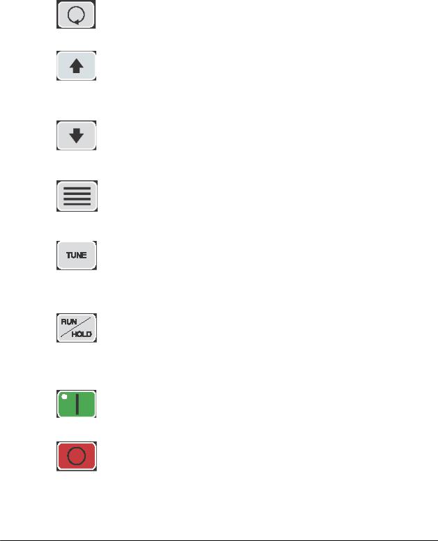
Keypad
Four keys, ‘Index’, ‘Up’, ‘Down’, and ‘Enter’ are used primarily to gain access to the menu structure and modify the controller’s parameters and features. The remaining six keys are used to direct the controller to start or stop a process.
Button |
Function |
|
|
|
|
|
• Used to advance to one of the three setup menus. |
|
|
• Used to advance to the next menu item when in a setup mode. |
|
|
• Used in conjunction with the Down button to go back to a previous menu item when in a |
|
Index |
setup mode. |
|
• Used in conjunction with the Enter button at power-on to break into Factory mode. |
||
|
||
|
• Used to increment the current setpoint value while system is in the normal running mode. |
|
|
Note that the rate speeds up when the key is held down. |
|
|
• Used to increment the current parameter value when in a setup mode. Note that the rate |
|
Up |
speeds up when the key is held down. |
|
• If pressed when the oil unit is in the “PmpRev” Shutdown mode, the Vent Output and the |
||
|
||
|
Alarm2 Output will be energized while the key is pressed. Use this function to reverse the |
|
|
pump in order to purge the mold of hot oil. |
|
|
• Used to decrease the current setpoint value while the system is in the normal running |
|
|
mode. Note that the rate speeds up when the key is held down. |
|
|
• Used to decrease the current parameter value when in a setup mode. Note that the rate |
|
Down |
speeds up when the key is held down. |
|
• If pressed when the Index button is being held down, returns to the previous menu item |
||
|
||
|
when in a setup mode. |
|
|
• Used to select one of the three setup modes. |
|
|
• Used to accept (save/write to EEPROM) the current indicated parameter value. |
|
|
• Note: No save/write occurs unless the Enter key is pressed before going to the |
|
Enter |
next/previous item or Setup mode is terminated. |
|
• Used in conjunction with the INDEX key at power-on to enter into the Factory |
||
|
||
|
mode. |
|
|
• If no Autotune operation is in progress, this button starts an Autotune operation. If an |
|
|
Autotune operation is in progress, pressing this button will immediately stop the Autotune |
|
|
operation. While the Autotune is running, the “Autotune” message is displayed on the |
|
Tune |
LCD in place of the normal “Running” message. |
|
• This key will not function if the Security Level is less than 3. |
||
|
||
|
• This key will not function if the Ramp/Soak operation is in progress. |
|
|
• This key will not function while in the Factory mode. |
|
|
• This key controls the Ramp/Soak process. If no Ramp/Soak operation is in progress, it starts |
|
|
the Ramp/Soak operation. When Ramp/ Soak is running, this key puts the Ramp/Soak |
|
|
operation into a hold condition. While the Ramp/Soak is running, the “Ramp/Soak” |
|
Run/Hold |
message is displayed on the LCD in place of the normal “Running” message. |
|
• This key will not function if the Security Level is less than 3. |
||
|
||
|
• This key will not function if the Ramp/Soak operation is in progress. |
|
|
• This key will not function while in the Factory mode. |
|
|
|
|
|
• When system is powered-on, the controller initializes and then displays the “[SYSTEM |
|
|
OFF]” message on the LCD. The controller is not functioning at this point. Pressing this |
|
|
START key enables all controller functions and lights the green power-on LED. After the |
|
Start |
system has been started, the “[Running]” message is displayed on the LCD. |
|
|
||
|
|
|
|
• Stops all controller functions and turns off the green power-on LED (overrides Remote |
|
|
Start input). After the system has been stopped, the “Stopped” message is displayed on the |
|
|
LCD. |
|
Stop |
• This key will override an existing Remote Start input switch closure. |
|
|
||
|
|
14 of 68

Button |
Function |
|
|
|
|
|
• When the system is first powered-on and the “Power Available - System Off” message |
|
|
is displayed, pressing the VENT key will turn on the Vent Output for a period of 8 |
|
|
seconds. The message “VENT” will be displayed during this period. |
|
Vent |
• When the system is running, pressing the VENT key shall manually turn on the Vent |
|
Output for as long as the key is held down, provided the ‘To Process’ temperature is |
||
|
below 150oF (65.5oC) for a water unit and 250oF (121oC) for an Oil |
|
|
unit. The message “Vent Time = MANUAL” will be displayed while the key is held |
|
|
down. |
|
|
• Turns off the Alarm 1 Output. The cause of the alarm will continue to appear in LCD |
|
|
until the fault is cleared. |
|
|
• Used to immediately terminate any of the three Setup modes without having to cycle |
|
Alarm |
through to the end of the menu items. Note that the current displayed parameter value |
|
is not saved to EEPROM when this key is pressed. |
||
Silence |
||
• Can be used as a means of turning on the LCD backlight without affecting any |
||
|
||
|
operation. |
Figure 1: Panel Layout
15 of 68

2-6 Menu Structure
The parameter menu structure is organized into three basic menus: Primary, Secondary, and Secure. To access the menus, press the Index button until the menu label appears in the second line of the LCD display. Additional menus display when an option is selected; however, the options are non-functional unless the appropriate menu option or option board has been installed. See the Menu Parameter Tables in the Appendix of this manual for more information.
Continuing to press the Index button scrolls from menu to menu. Press the Enter button to enter the menu, and use the Index button to scroll through the parameters of the menu. Once you find the parameter that needs to be changed, use the Up and Down buttons to change the parameter. Press the Enter button to accept the new value.
You can exit the setup menus by scrolling through the menu to its end or by pressing the Alarm Silence button. The controller will automatically exit the setup menu if no buttons have been pressed for more than one minute.
Primary Menu
The Primary menu includes all non-critical parameters for standard operation including but not limited to standby mode, mold temperature, alarm trip points, ramp/soak settings, and high heat.
Secondary Menu
The Secondary menu includes all non-critical parameters for optional equipment including but not limited to degrees F/C, Alarm parameters, ramp/soak segments, remote setpoint scaling, communication setup, and retransmission scaling.
Secure Menu
The Secure menu includes all critical parameters for setting up the controller including but not limited to controller function, select either Water TCU or Oil TCU default values, flow meter on/off, remote control probe on/off, pressure switch, high and low level, safety thermostat on/off, output parameters, and scale limits.
16 of 68

2-7 Passwords and Security
The controller provides four levels of security. Depending on the security level, some or all of the setup menus may be locked. The security level must be changed in order to unlock these menus. The current security level is displayed in the lower right corner of the menu display. The default security level is 3.
Security levels are changed by changing the password value using the Up and Down buttons and pressing the Enter button. Values in the setup menus can be changed only when the correct security level is set. Note that the security level value itself can be changed in any security level.
Use the following procedure to change the security level:
1.Press the Index button three times to access the Secure menu.
2.Press the Enter button. The LCD screen will display the current security level.
3.Use the Up or Down buttons to change the value in the display line to the password of the new desired security level.
4.Press the Enter button to select this new security level and retain the value in EEPROM. The display will change from the password value to the selected security level for that password.
Level |
Password |
Menu |
Status |
Description |
|
|
|
Primary |
Locked |
No parameter values can be |
|
1 |
110 |
Secondary |
Locked |
changed. |
|
Secure |
Locked |
Setpoint can be changed. Alarm |
|||
|
|
||||
|
|
|
|
silence button active. |
|
|
|
Primary |
Unlocked |
Only the primary menu values |
|
2 |
101 |
Secondary |
Locked |
can be changed. |
|
|
|
|
|
Setpoint can be changed. |
|
|
|
Secure |
Locked |
||
|
|
Primary |
Unlocked |
Only the primary and secondary |
|
3 |
011 |
Secondary |
Unlocked |
menu values can be changed. |
|
|
|
|
|
Setpoint can be changed. |
|
|
|
Secure |
Locked |
||
|
|
Primary |
Unlocked |
All parameter values can be |
|
4 |
111 |
Secondary |
Unlocked |
changed. |
|
|
|
Secure |
Unlocked |
Setpoint can be changed. |
17 of 68

Advanced Microprocessor Controller
Chapter 3: Installation
3-1 Location
Mount the instrument in a location that will not be subject to excessive temperature, shock or vibration. All models are designed for mounting in an enclosed panel.
When properly mounted in an enclosed panel using a gasket at the panel/controller interface, the keypad can be washed down with water. Do not use high-pressure fluids.
3-2 Electrical Connections
Microprocessor-based instruments require a “clean” source of power that is steady and free of noise. Electrical noise may be caused by line faults, power switching, motors, motor controllers, or power controllers containing SCR devices. Without a clean source, any microprocessor is prone to failure. If your power source is not from a clean line, your system can be protected by installing a line filter.
Where external contactors or solenoids are used with relay output instruments, an R/C Snubber Network should be used. The snubber installs easily directly across the field coil terminals of the relay or solenoid.
Do not run thermocouples, RTD’s or other class 2 wiring in the same conduit or area as the power leads. Maintain separation between wiring of sensors, process signals and other power and control wiring.
19 of 68
Chapter 4: Basic Operation
4-1 Turning the Power On
When AC power is first applied to the unit, the following sequence of events will occur:
1.The LCD backlight lights up.
2.The LCD displays dashes: LEDs have all segments on.
3.The LCD displays the PROM Rev/Date.
4.The LCD displays “SelfTest in Progress.”
5.If the ‘Debug’ parameter is enabled, the following messages about Option Cards can be displayed:
•Re-Transmit Detected
•Cool Analog Detected
•Heat Analog Detected
•Serial Comm Detected
•None Installed
6.The LED segments turn off.
7.The LCD backlight turns off.
8.The LCD displays “Power Available/System OFF.”
At this point, a Manual Vent Operation can be initializeed for 8 seconds by pressing the Vent button.
The unit is now in a standby mode of operation. No system process control will occur until the Start button is pressed.
21 of 68
 Loading...