

Page 1

Operating Manual
NJT: Expert900 Install. & Initial Setup
Page 2
NJT: Expert900 Install. & Initial Setup
Copyright & Revision History
The copyright to this document is owned by ACS Solutions Switzerland Ltd. All documentation is
confidential and must not be disclosed to third parties without the prior written consent of ACS Solutions
Switzerland Ltd. The document must not be reproduced in any way. Violation is liable to prosecution.
The documentation describes the current status of the product design at the time of drafting or updating the
document. Changes and improvements, due to advances in technology and functionality, may be introduced
without prior notice or justification.
ACS Solutions Switzerland Ltd. is not liable for any indirect damages incurred by the user as a result of
using this document.
Copyright 29. Mar. 07 by ACS Solutions Switzerland Ltd.
Frankenstrasse 70
CH-3018 Bern
Switzerland
Document Administration
Author(s)
Date 29.03.2007 Language EN Original Language EN
Doc-Nr. 10-000-004-711 Sub-No.: 06 Version 01
Document-Type BH Operating Manual Format
Tool Microsoft Word 2000 Location SAP-PDM
Roger Vifian
Revision History
Vers. Description of Changes
00 First edition
01 FCC authorization; ground connection & special track ground connection
2 / 47 Version: 01 ACS Doc-No: 10-000-004-711 - BH - 06 - EN
Page 3

NJT: Expert900 Install. & Initial Setup
Table of Contents
1 Reference Documents.....................................................................................4
2 FCC Authorization & Rules.............................................................................5
3 Overview...........................................................................................................6
3.1 Basic Steps.........................................................................................................................6
4 Installation........................................................................................................7
4.1 Setup Conditions.................................................................................................................7
4.2 Minimum Clearance Requirements.....................................................................................7
4.3 Recommendations for the Installation of the Pedestal......................................................10
4.4 Installation of TVM onto the Pedestal................................................................................11
4.4.1 Description of the Attachment of the TVM to the Pedestal................................11
4.4.2 Installation with Lifting Device...........................................................................13
4.4.3 Installation Manually..........................................................................................17
4.5 Installation of EFT – PoS Card Processing.......................................................................22
4.6 Connecting the TVM to the Mains.....................................................................................23
4.6.1 Power Requirements.........................................................................................23
4.6.2 Procedure.........................................................................................................24
4.7 Connecting the TVM to the Network..................................................................................27
4.7.1 Network Connection with Shielded Cable Connection......................................27
4.7.2 Network Connection with Unshielded Cable Connection..................................28
5 Initial Start-up................................................................................................29
5.1 Overview...........................................................................................................................29
5.2 Requirements....................................................................................................................29
5.3 Special tools......................................................................................................................30
5.4 Starting up the TVM..........................................................................................................30
5.4.1 Remove Packaging Material andTransport Security Locks..............................30
5.4.2 Software Installation..........................................................................................30
5.4.3 Terminal Initialization........................................................................................31
5.4.4 Load Paper (Ticket Media)................................................................................36
5.4.5 Inspecting Coin Vault, Banknote Vault & BUCOs.............................................36
5.4.6 Initializing the Printer System............................................................................37
5.4.7 Initializing the Coin Processing System............................................................40
5.4.8 Fill the Coin Drums of the Coin Processing System.........................................41
5.4.9 Initializing the Banknote Verifier........................................................................44
5.4.10 Initializing the Card Handling Module (option)..................................................46
5.4.11 Commissioning of the EFT-PoS Card Processing............................................47
5.4.12 Initializing the Sales Application........................................................................47
ACS Doc-No: 10-000-004-711 - BH - 06 - EN Version: 01 Seite 3 / 47
Page 4

NJT: Expert900 Install. & Initial Setup
1 Reference Documents
Document number
10-000-004-582 E00 Safety Instructions
10-000-004-711 E01 NJT: Expert900 System Description
10-000-004-711 E02 NJT: Expert900 Routine Jobs
10-000-004-711 E03 NJT: Expert900 Maintenance Jobs
10-000-004-711 E04 NJT: Expert900 Replacing Modules
10-000-004-711 E05 NJT: Expert900 Error Codes
Document Title
4 / 47 Version: 01 ACS Doc-No: 10-000-004-711 - BH - 06 - EN
Page 5
NJT: Expert900 Install. & Initial Setup
2 FCC Authorization & Rules
This TVM (Ticket vending machine) complies to the standards and
regulations of the FCC (Federal Communications Commission, USA).
Read through following statements to get familiar with the FCC
regulations:
Statement Required by 15.19 and RSS210
This TVM complies with part 15 of the FCC Rules.
Operation is subject to the following two conditions:
− this TVM may not cause harmful interference, and
− this TVM must accept any interference received, including
interference that may cause undesired operation.
Statement Required by 15.2
Important Note
Changes or modifications made to this TVM not expressly approved by
ACS USA may void the FCC authorization to operate this TVM.
Important Note: FCC Radiation Exposure Statement
This TVM complies with FCC radiation exposure limits set forth for an
uncontrolled environment. This TVM should be installed and operated
with minimum distance of 20cm between the radiator and your body. This
transmitter must not be co-located or operating in conjunction with any
other antenna or transmitter.
ACS Doc-No: 10-000-004-711 - BH - 06 - EN Version: 01 Seite 5 / 47
Page 6

NJT: Expert900 Install. & Initial Setup
3 Overview
The following document describes the steps for the initial installation and
initialization of the unit.
3.1 Basic Steps
The following are the principle steps in installing a TVM and starting it
up for the first time:
1 Check the shipment to make sure it is complete.
2 Prepare the area where the TVM is to be installed; drill holes for
anchor rods, mount anchor rods
3 Anchor pedestal at the location where the TVM is to be installed.
4 Install the TVM onto the pedestal.
5 Install the EFT-PoS terminal (if not installed already)
6 Hook up power supply and network cables.
7 Load ticket media and insert cash vaults and BUCOs.
8 Turn on the TVM; initialize the TVM.
6 / 47 Version: 01 ACS Doc-No: 10-000-004-711 - BH - 06 - EN
Page 7

NJT: Expert900 Install. & Initial Setup
4 Installation
4.1 Setup Conditions
Please note
Always observe local safety precautions and those of the railway or bus
company in question.
• Do not expose TVM to direct sunlight.
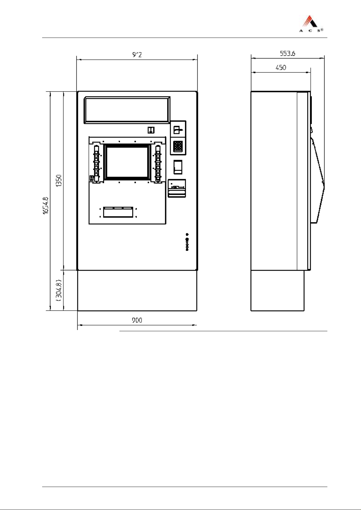
• Space requirements for installation of the pedestal: 900mm × 450mm.
• The TVM must be situated on a flat, level concrete floor with surface
irregularities not exceeding 1 mm.
• Do not locate the TVM near emergency escape routes.
4.2 Minimum Clearance Requirements
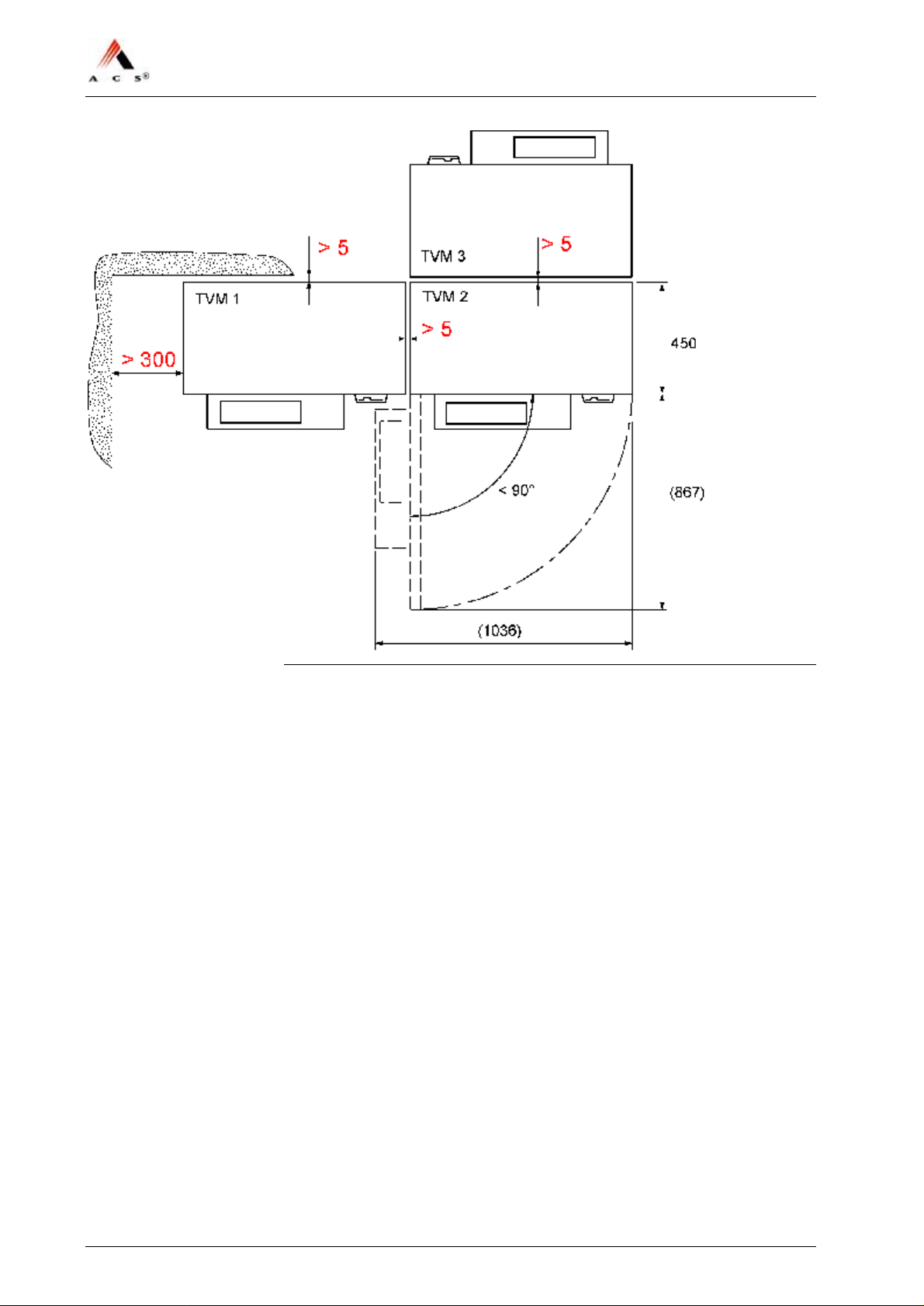
Maintenance requirements call for the following minimum clearance
between TVMs installed next to one another.
• At least 85 mm between two TVM
• At least 5 mm between any wall and the rear of the TVM
• At least 270 mm between the TVM and any wall to its left.
ACS Doc-No: 10-000-004-711 - BH - 06 - EN Version: 01 Seite 7 / 47
Page 8
NJT: Expert900 Install. & Initial Setup
Figure 1: Top view: Minimum clearance requirements
8 / 47 Version: 01 ACS Doc-No: 10-000-004-711 - BH - 06 - EN
Page 9
NJT: Expert900 Install. & Initial Setup
Figure 1: Dimensions TVM
ACS Doc-No: 10-000-004-711 - BH - 06 - EN Version: 01 Seite 9 / 47
Page 10

NJT: Expert900 Install. & Initial Setup
4.3 Recommendations for the Installation of the
Pedestal
Mechanical Stability
The pedestal mountings must remain mechanically stable under the
following loads: stress = 5500N, strain = 2000N (forces measured at each
mounting point).
Recommended Mounting Fixtures
The installation accessories shipped along with the TVM only include the
mounting fixtures required for mounting the TVM/AVM onto the
pedestal.
Hilti AG anchor rods (model HAS-E-F-M16 × 260/108) and adhesive
capsule anchors (model HVU M16 × 125) have become the standard
fixtures for anchoring the pedestal at the installation site. These anchoring
fixtures can be obtained worldwide from Hilti AG. Additional information
is available online at www.hilti.com, where you will also find the
appropriate instructions for use.
Installation Requirements
• The power cable and network cable must be ready for connection and
properly installed in the concrete base.
• Up-to-date instructions for mounting anchor rods should be on hand
from the rod manufacturer.
Special Tools
• Key for the pedestal door (if lock is present)
Procedure
Warning! – Risk of electric shock!
Make certain that all of the cables you will be handling have been
disconnected from any source of electricity and that they remain so during
installation.
1 Check to make sure that the location for the TVM is level and clean.
2 Drill holes for the anchor rods according to instructions and tables
provided by the manufacturer of the anchoring fixtures.
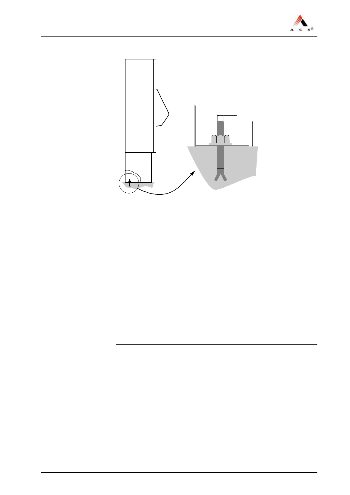
Please note that, once installed, the anchor rod must extend out of the
floor by at least 50 mm (max. 80mm):
10 / 47 Version: 01 ACS Doc-No: 10-000-004-711 - BH - 06 - EN
Page 11
NJT: Expert900 Install. & Initial Setup
B
B
M16
> 50
Figure 2: Pedestal anchoring
3 Secure the anchor rods according to instructions and tables provided
by the anchor rod manufacturer.
4 Bolt the pedestal at each mounting point using M16 nuts and M16
washers, taking care to avoid exceeding the maximum allowable
torque for the anchor rods.
The pedestal is now fully installed.
4.4 Installation of TVM onto the Pedestal
Do not scoot the TVM across rough surfaces, as this could potentially
destroy the surface coatings of the cabinet.
Instead, lower the TVM onto the pedestal in stages using hardwood
blocks as described in this section.
4.4.1 Description of the Attachment of the TVM to the
Pedestal
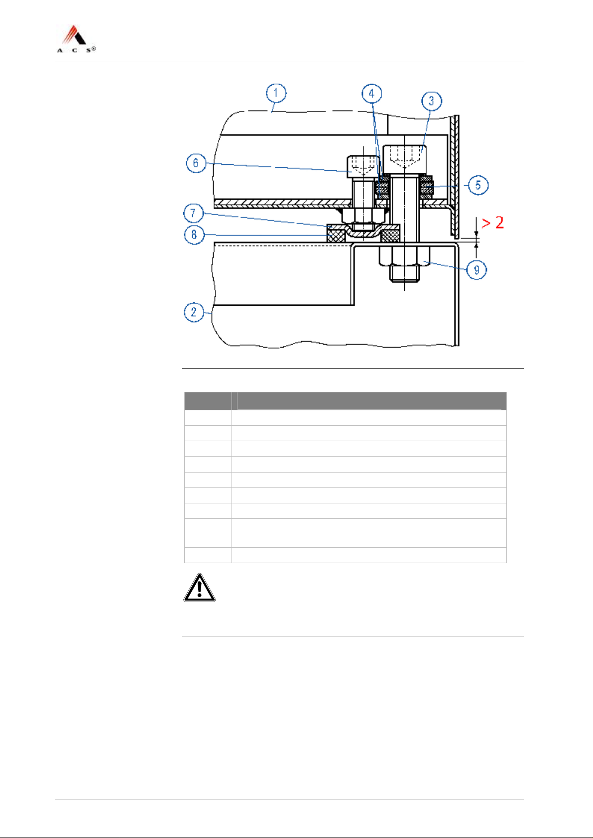
The properly installed TVM actually sits on the rubber supports of the
nivelling set and not directly on the pedestal, see Figure 3 on page 12.
The rubber supports acts as shock absorber.
ACS Doc-No: 10-000-004-711 - BH - 06 - EN Version: 01 Seite 11 / 47
Page 12
NJT: Expert900 Install. & Initial Setup
Figure 3: Cross-section of the Attachment
No.
Description
1 TVM
2 Pedestal
3 M16×60 mounting bolt
4 17/30×30 washer
5 Rubber washer
6 M12×60 leveling screw
7 Metal support
8 Rubber support: forms the nivelling plate together with
metal support of pos 7
9 Welded nut (on holes drilled in the pedestal)
Important!
Make sure that there must be a gap between the TVM and pedestal of at
least 2mm.
12 / 47 Version: 01 ACS Doc-No: 10-000-004-711 - BH - 06 - EN
Page 13
NJT: Expert900 Install. & Initial Setup
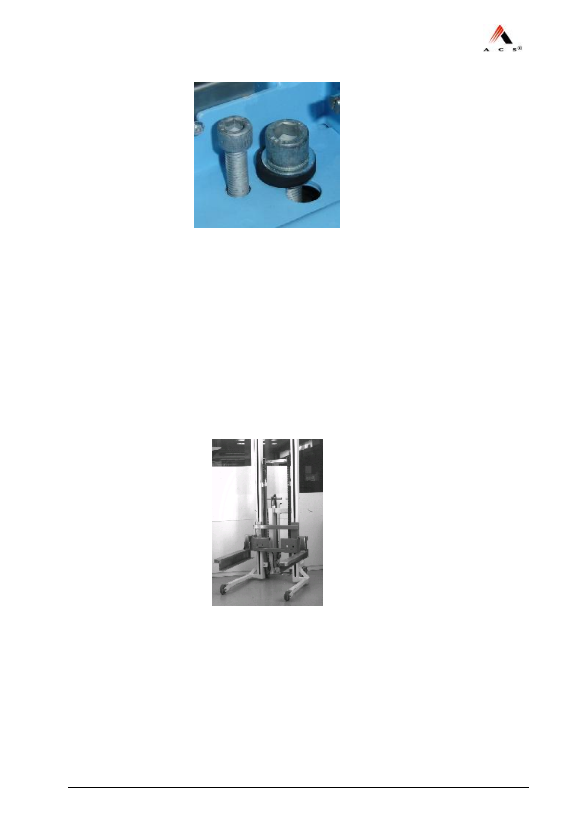
Figure 4: Attachment TVM to Pedestal upon completion
4.4.2 Installation with Lifting Device
Requirements
• The pedestal must be fully installed (with the electric and network
cables installed in the pedestal).
Special tools
• Door keys
• Pedestal door key (if necessary)
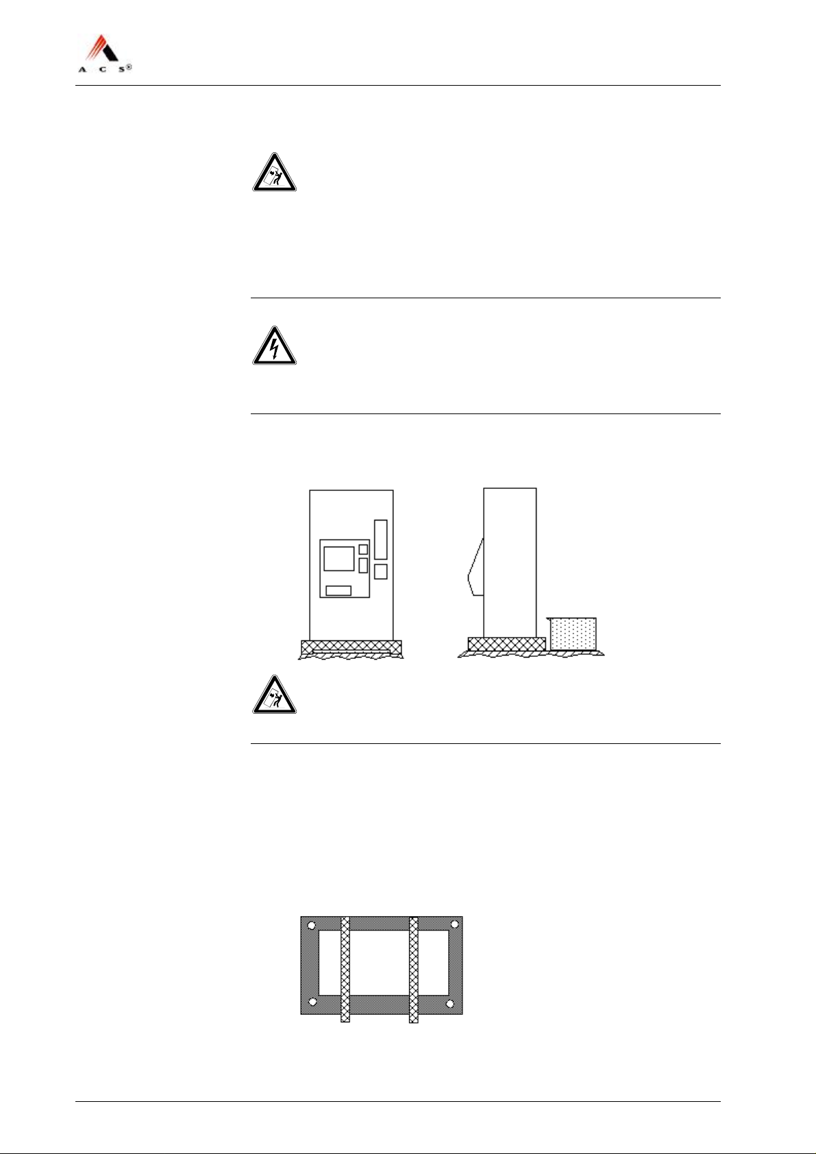
• Lifting device to lift the TVM up to base height:
• Support plates, 2pcs, order number 851.9763/01 (not part of the
delivery)
ACS Doc-No: 10-000-004-711 - BH - 06 - EN Version: 01 Seite 13 / 47
Page 14
NJT: Expert900 Install. & Initial Setup
Procedure
Warning! – TVM might tip if not properly secured!
Until it is fully installed, the TVM will tip over when the door is opened,
potentially crushing anyone it falls on.
All operations should be performed, if at all possible, with the door
closed. If this is not feasible, the TVM must be secured so that it cannot
tip over.
Danger! – Risk of electric shock!
Make certain that all cables have been disconnected from any source of
electricity and that they remain so while working on the TVM.
1 Move the TVM, which sits on its skid on the platform, in front of the
installed pedestal:
Warning! – TVM might tip if not properly secured!
TVM must be secured so that it cannot tip over.
2 Make sure that somebody holds the TVM to protect it from falling
over. Open only now the door.
3 Remove the screws that hold the unit to the skid.
4 Close the TVM door again.
5 Put support plates onto the pedestal:
14 / 47 Version: 01 ACS Doc-No: 10-000-004-711 - BH - 06 - EN
Page 15
NJT: Expert900 Install. & Initial Setup
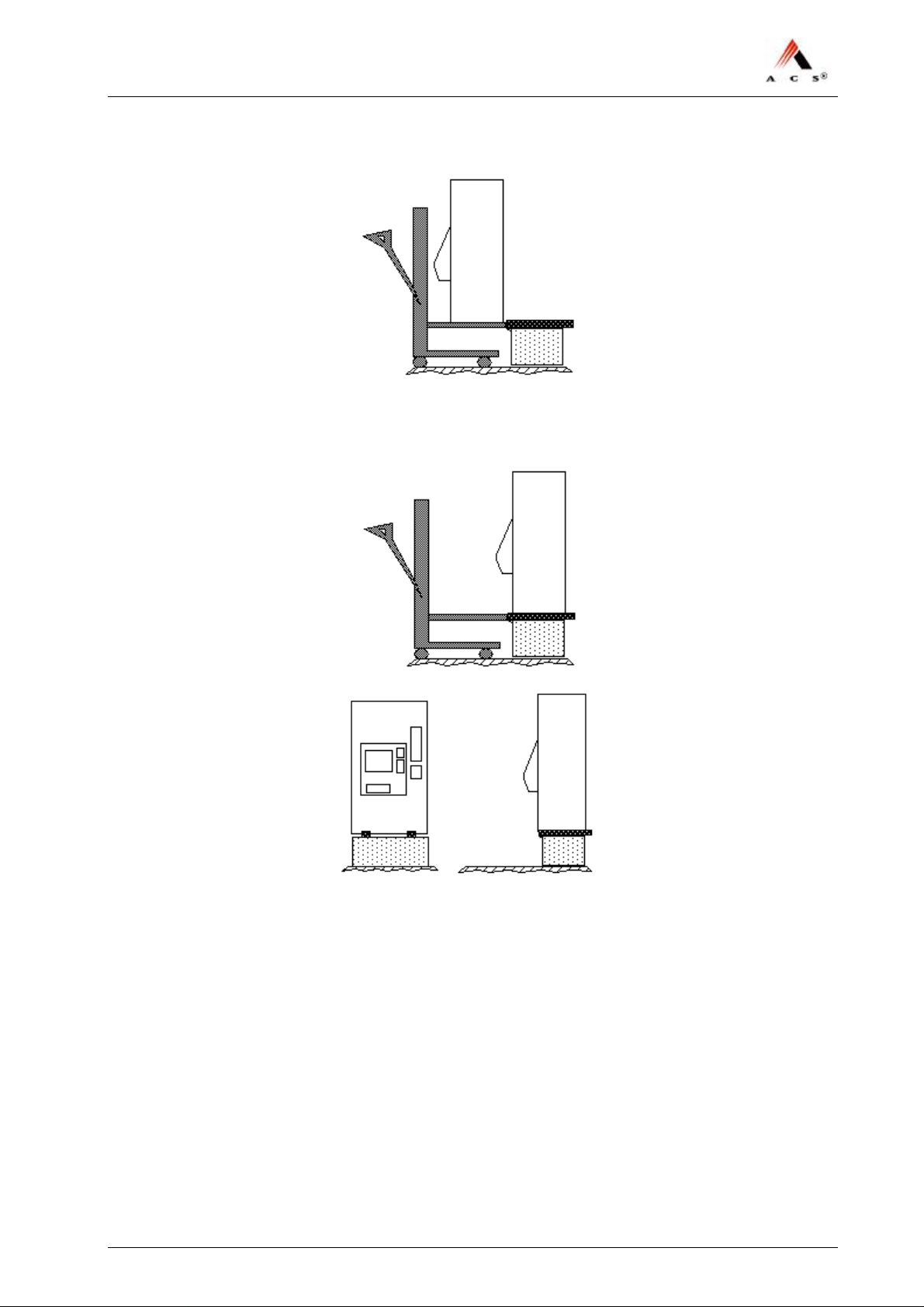
6 Lift the TVM up to pedestal height:
7 Slide the TVM over the wooden blocks onto the pedestal and align it
to the pedestal:
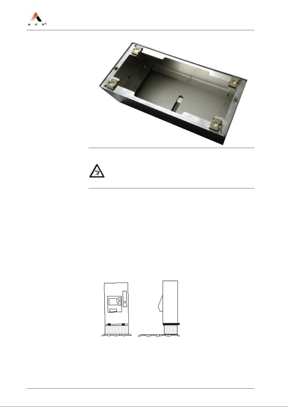
8 Set nivelling plates (consisting of the metal support, pos7, and rubber
support, pos 8, in Figure 3 on page 12) in the appropriate places on
the base by each mounting hole:
ACS Doc-No: 10-000-004-711 - BH - 06 - EN Version: 01 Seite 15 / 47
Page 16
NJT: Expert900 Install. & Initial Setup
Figure 5: Arrangement of the nivelling plates
Warning! –TVM might tip if not properly secured!
TVM must be secured so that it cannot tip over.
9 Open door. Lift door upwards in front and hold it until unit is secured
(point 10). Lock door in place with horizontal door lever to prevent
closing of door.
10 Insert washers, rubber washer and mounting bolts into the two back
holes of the TVM as shown in Figure 3 on page 12.Tighten them
slightly to ensure that the TVM cannot tip over anymore.
11 Install the mounting bolts in the front in the same way.
12 Install all 4 leveling screws provisionally.
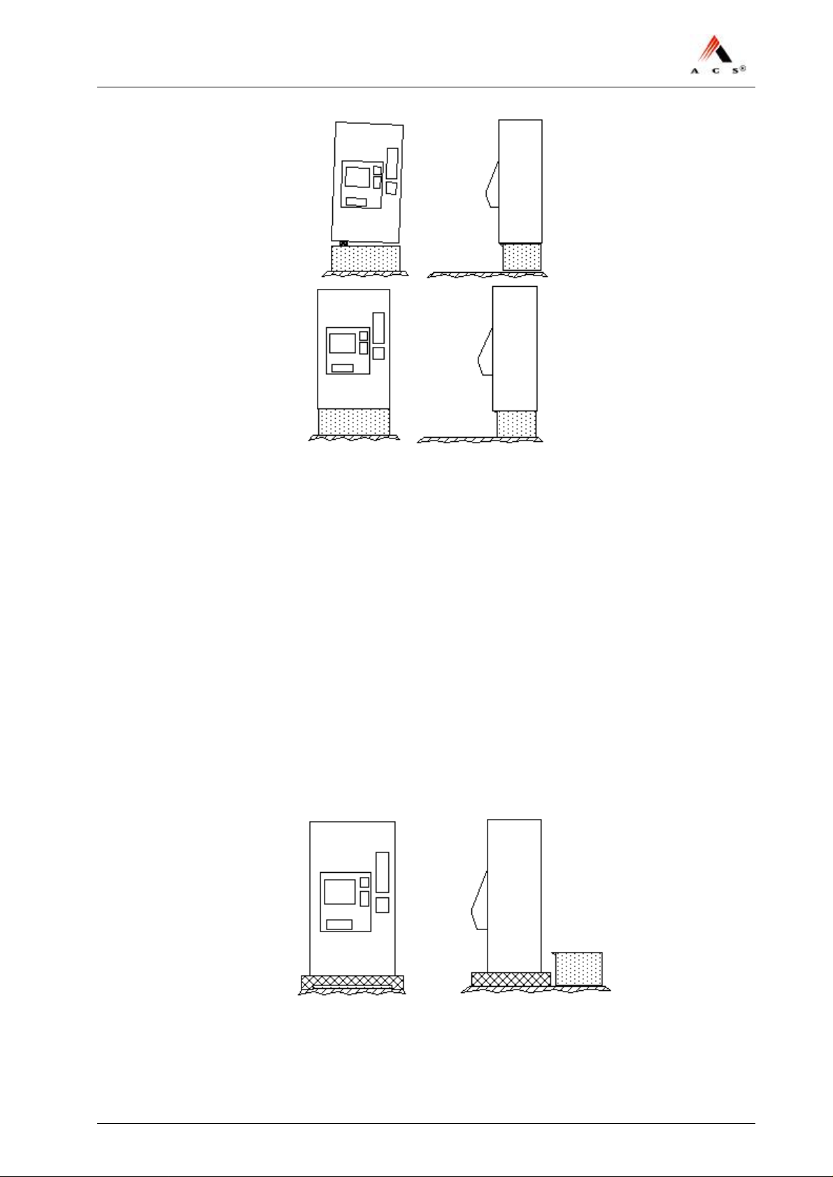
13 Push TVM top left and top right to remove the wooden blocks as
illustrated in the next 3 figures:
16 / 47 Version: 01 ACS Doc-No: 10-000-004-711 - BH - 06 - EN
Page 17
NJT: Expert900 Install. & Initial Setup
14 Tighten leveling screws so far down until the TVM stays
approximately 2 mm off the pedestal (see Figure 3 on page 12). You
can also level the TVM slightly with these screws.
15 Tighten the mounting bolts properly down.
End.
4.4.3 Installation Manually
If there is no lifting device present or if such a device cannot be used due
to a shortage of place, the manual installation must be applied.
Requirements
• The pedestal must be fully installed (with the electric and network
cables installed in the pedestal).
• Before starting with the manual installation, the TVM should be
positioned in front of the installed pedestal:
Special tools
• Door key
ACS Doc-No: 10-000-004-711 - BH - 06 - EN Version: 01 Seite 17 / 47
Page 18
NJT: Expert900 Install. & Initial Setup
• Pedestal door key
• Wood blocks to support the skid while lifting the unit to its
appropriate height manually.
Procedure
Warning! – TVM might tip if not properly secured!
Until it is fully installed, the TVM will tip over when the door is opened,
potentially crushing anyone it falls on.
All operations should be performed, if at all possible, with the door
closed. If this is not feasible, the TVM must be secured so that it cannot
tip over.
Danger! – Risk of electric shock!
Make certain that all cables have been disconnected from any source of
electricity and that they remain so while working on the TVM.
Note:
Do not unscrew TVM from skid prior to this procedure!
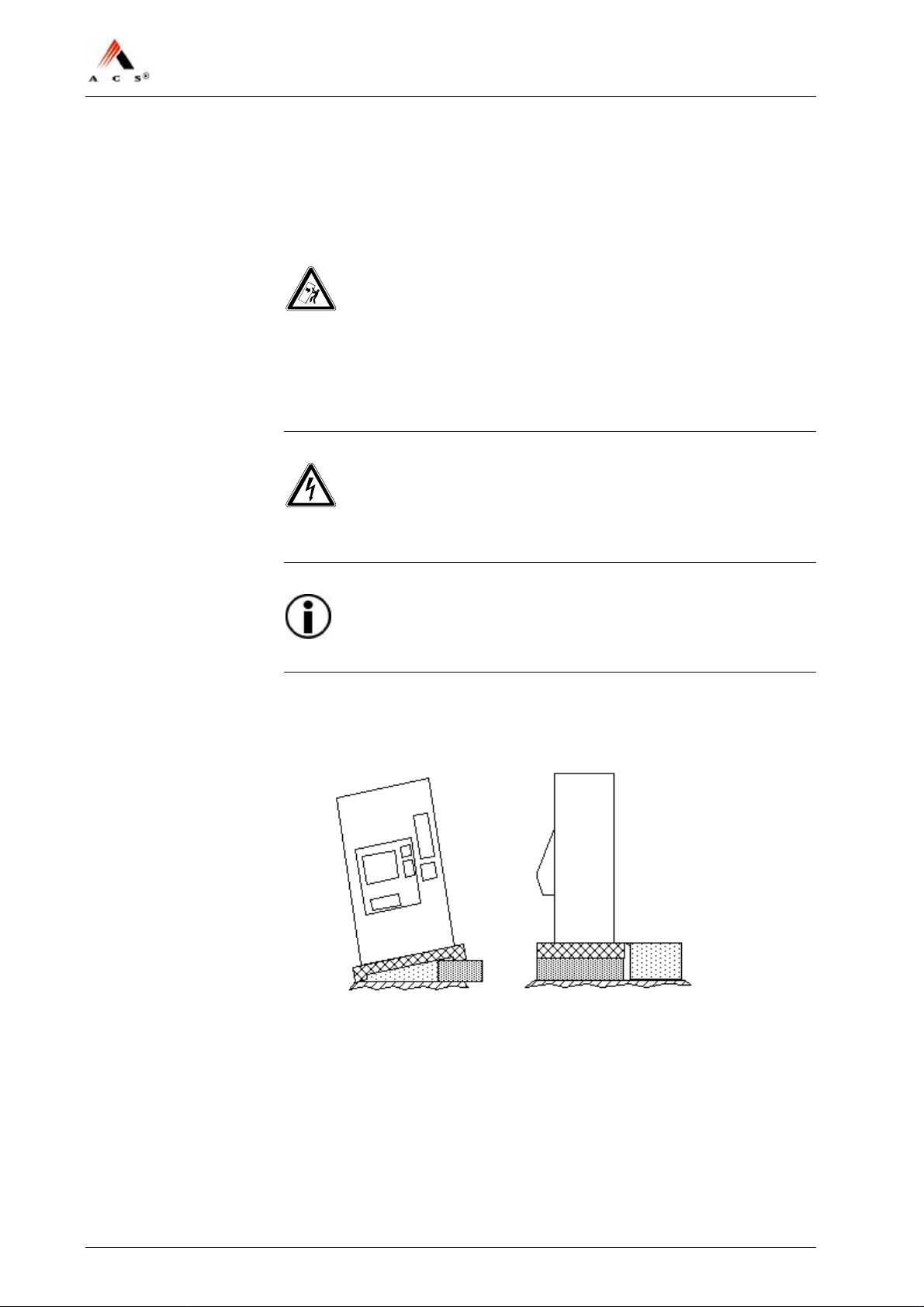
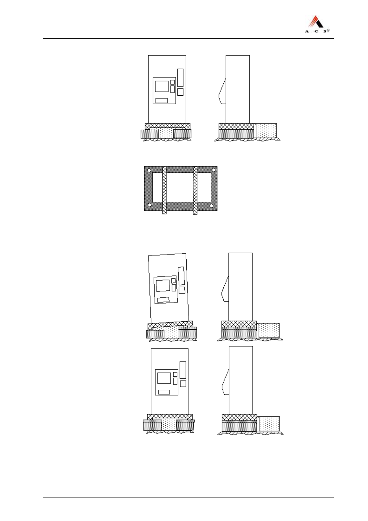
1 Tip TVM over to the left (2 persons left hand side one person right
hand side) and insert a skid wide wooden block (half size skid also
possible):
2 Repeat the previous step from the right hand side and bring the TVM
to the same level as the height of the pedestal:
18 / 47 Version: 01 ACS Doc-No: 10-000-004-711 - BH - 06 - EN
Page 19
NJT: Expert900 Install. & Initial Setup
3 Put two pieces of wood of about 4 cm height onto the pedestal:
4 Apply the previous steps again to insert a piece of wood to bring the
TVM up to the same level as the pieces of wood (4cm above pedestal)
as illustrated in next two figures:
ACS Doc-No: 10-000-004-711 - BH - 06 - EN Version: 01 Seite 19 / 47
Page 20
NJT: Expert900 Install. & Initial Setup
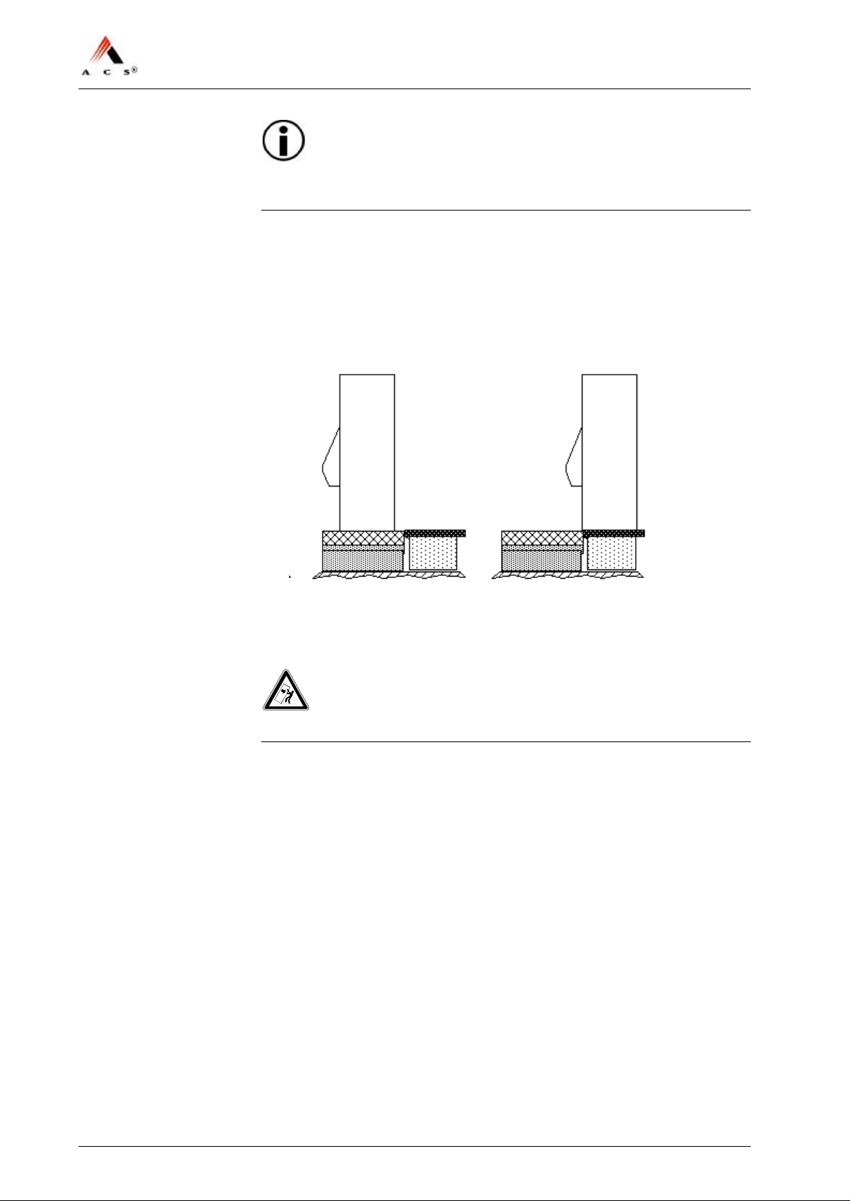
Note:
The steps for lifting the TVM can be increased using smaller pieces of
wood!
5 Make sure that somebody holds the TVM to protect it from falling
over. Open only now the door.
6 Remove the screws that hold the unit to the skid.
7 Close and lock door of the TVM.
8 Slide TVM onto the pedestal:
9 Set nivelling plates (consisting of the metal support, pos7, and rubber
support, pos 8, in Figure 3 on page 12) in the appropriate places on
the base by each mounting hole according to Figure 5 on page 16.
Warning! – TVM might tip if not properly secured!
TVM must be secured so that it cannot tip over.
10 Open door. Lift door upwards in front and hold it until unit is secured
(point 10). Lock door in place with horizontal door lever to prevent
closing of door.
11 Insert washers, rubber washer and mounting bolts into the two back
holes of the TVM as shown in Figure 3 on page 12.Tighten them
slightly to ensure that the TVM cannot tip over anymore.
12 Install the mounting bolts in the front in the same way.
13 Install all 4 leveling screws provisionally.
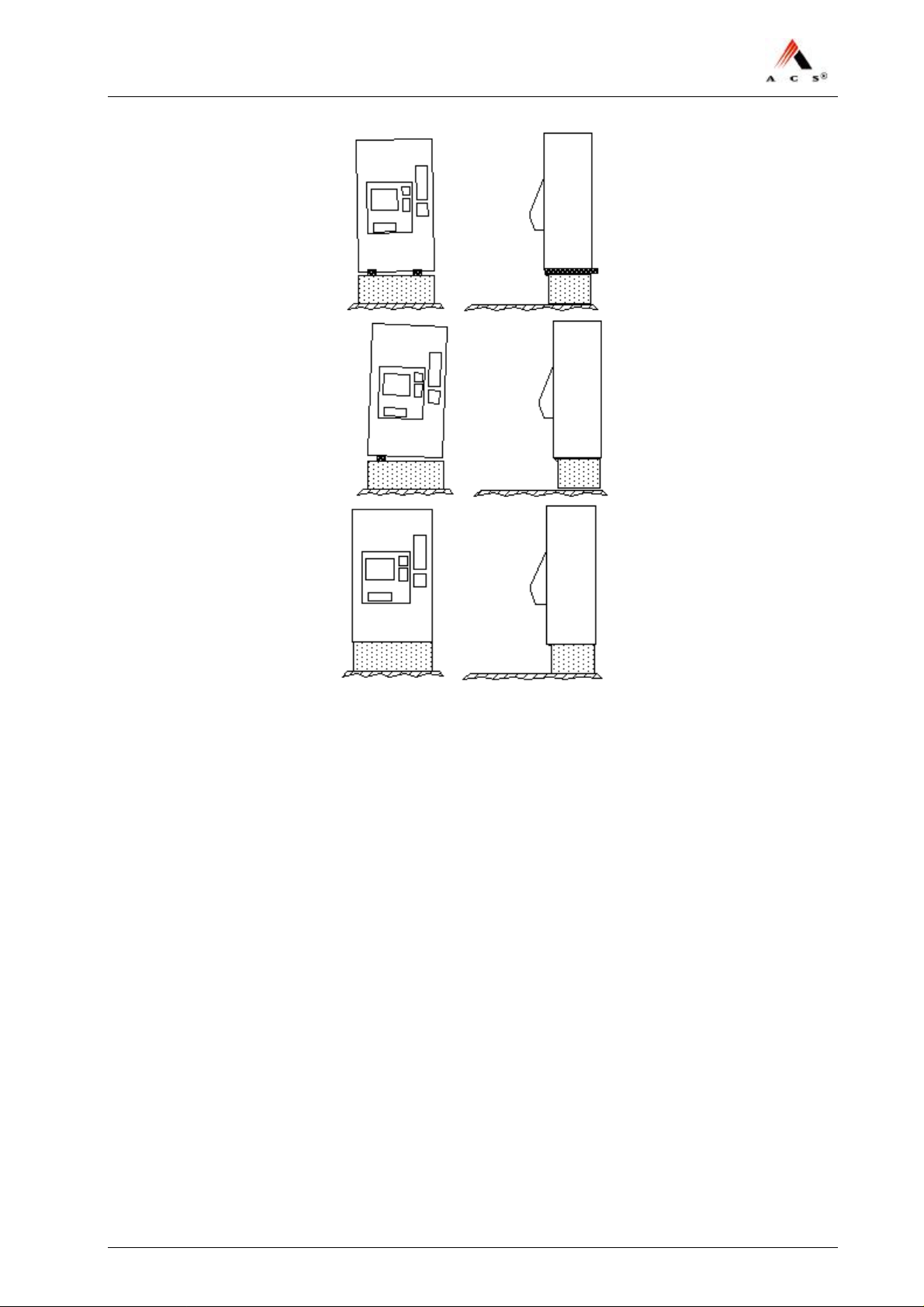
14 Push TVM top left and top right to remove the wooden blocks as
illustrated in the next 3 figures:
20 / 47 Version: 01 ACS Doc-No: 10-000-004-711 - BH - 06 - EN
Page 21
NJT: Expert900 Install. & Initial Setup
15 Tighten leveling screws so far down until the TVM stays
approximately 2 mm off the pedestal (see Figure 3 on page 12). You
can also level the TVM slightly with these screws.
16 Tighten the mounting bolts properly down.
End.
ACS Doc-No: 10-000-004-711 - BH - 06 - EN Version: 01 Seite 21 / 47
Page 22

NJT: Expert900 Install. & Initial Setup
Warning! – TVM might tip over if not properly secured!
Until it is fully installed, the TVM will tip over when the door is opened,
potentially crushing anyone it falls on.
All operations should be performed, if at all possible, with the door
closed. If this is not feasible, the TVM must be secured so that it cannot
tip over.
17 Criteria for determining if TVM is level:
– Door should open easily. Plug-in units for modules such as the
banknote acceptor should be easy to activate.
– There should be at least 2mm of clearance between the TVM and
the pedestal.
The physical installation of the TVM is now complete.
End.
4.5 Installation of EFT – PoS Card Processing
Not delivered by ACS Solutions Switzerland Ltd. but preinstalled by
ACS.
22 / 47 Version: 01 ACS Doc-No: 10-000-004-711 - BH - 06 - EN
Page 23

NJT: Expert900 Install. & Initial Setup
4.6 Connecting the TVM to the Mains
4.6.1 Power Requirements
• AC input: 115V (93V–132V)
• Frequency: 60Hz (47–63)
• Power consumption
− without heating: < 2.8A
− with heating: 12A
• The TVM supply line has to be fused with a 20A fuse
• 5 seconds power interruptions support.
• Communication: The TVM offers one Ethernet 10baseT / 100baseTx
interface. For the Ethernet lines from a TVM to the next network
equipment shielded cables are required.
Note:
Installation must be done according to national installation requirements.
ACS Solutions Switzerland Ltd. does not design, install and maintain the
LAN on which the TVM is connected.
ACS Doc-No: 10-000-004-711 - BH - 06 - EN Version: 01 Seite 23 / 47
Page 24
NJT: Expert900 Install. & Initial Setup
4.6.2 Procedure
1 Make certain that the main switch on the TVM is in the off (‘0’)
position.
Warning! – Risk of electric shock!
Make certain that all of the cables you will be handling have been
disconnected from any source of electricity and that they remain so during
installation.
2 Remove the insulation from the power cable to about 8 mm.
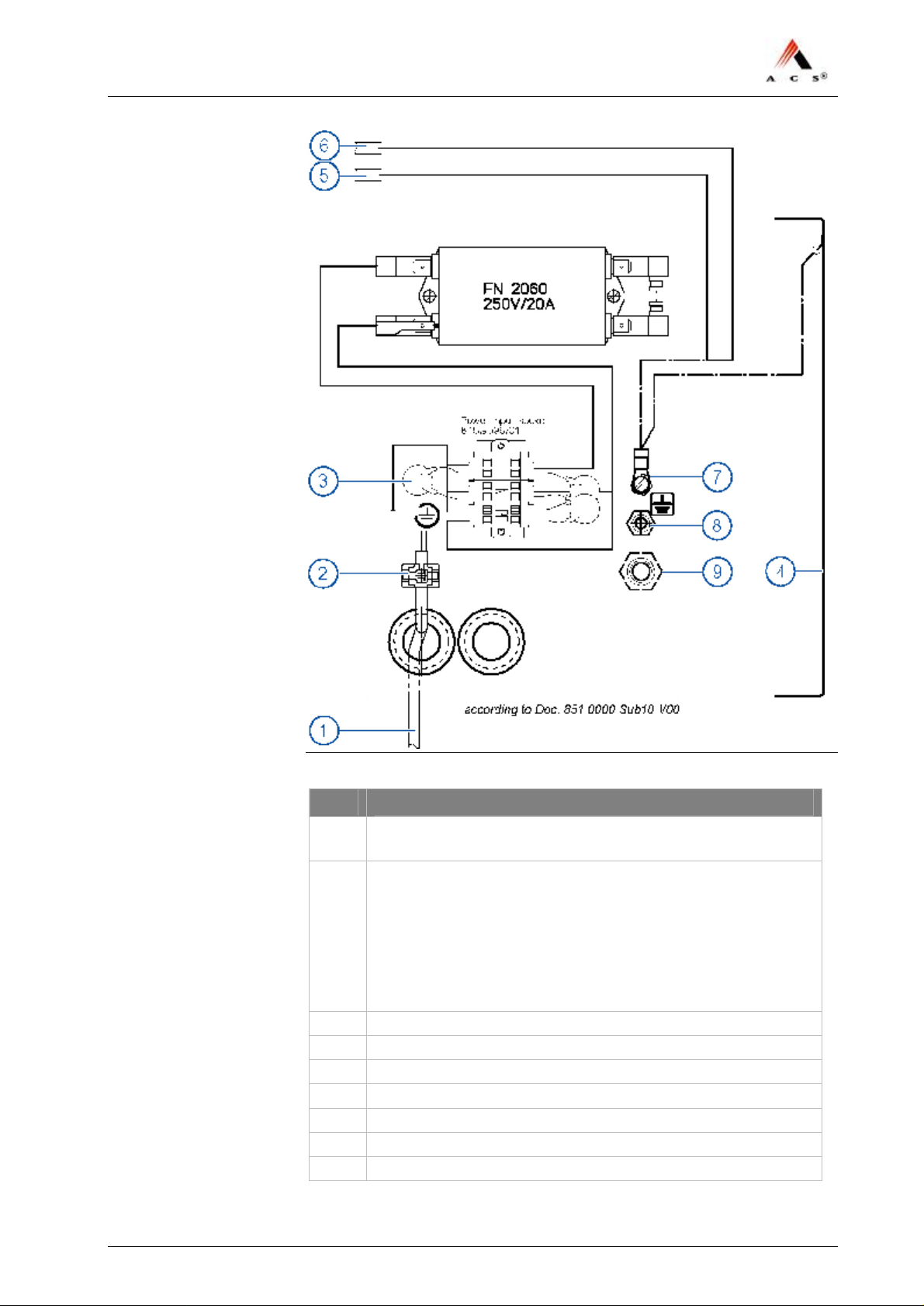
3 Open the cover and connect the cable to the terminal as shown in
Figure 6, making sure that the polarity is correct.
Important!
The TVM must be grounded to earth with a minimum cross-section of
AWG12 (4 mm2). Choose the power cord accordingly.
4 Use cable fasteners to provide strain relief.
24 / 47 Version: 01 ACS Doc-No: 10-000-004-711 - BH - 06 - EN
Page 25
NJT: Expert900 Install. & Initial Setup
Figure 6: Cable layout for individual TVM
No.
Description
1 Power cord: 3×AWG12 (3×4mm2 maximum)
insulation removed to 8mm
2 Cable fastener e.g.
– small BT1M-M 2.4×92mm Thomas&Belts (918.0551)
– large TY25M 4.8×186mm Thomas&Belts (918.0552)
Cable fastener
Mounting plate for cable fastener, e.g.
– small TC-140 Thomas&Belts (918.0551)
– large TC-141 Thomas&Belts (918.0562)
3 Overvoltage protection (varistor)
4 Cover
5 to circuit-breaker
6 to GFCI service plug
7 M4-ground connection
8 M6-ground connection
9 M10-ground connection
ACS Doc-No: 10-000-004-711 - BH - 06 - EN Version: 01 Seite 25 / 47
Page 26
NJT: Expert900 Install. & Initial Setup
5 Make sure that there is a ground cable connecting the pedestal with
the TVM housing; connect it to pos 7, 8 or 9 in Figure 6.
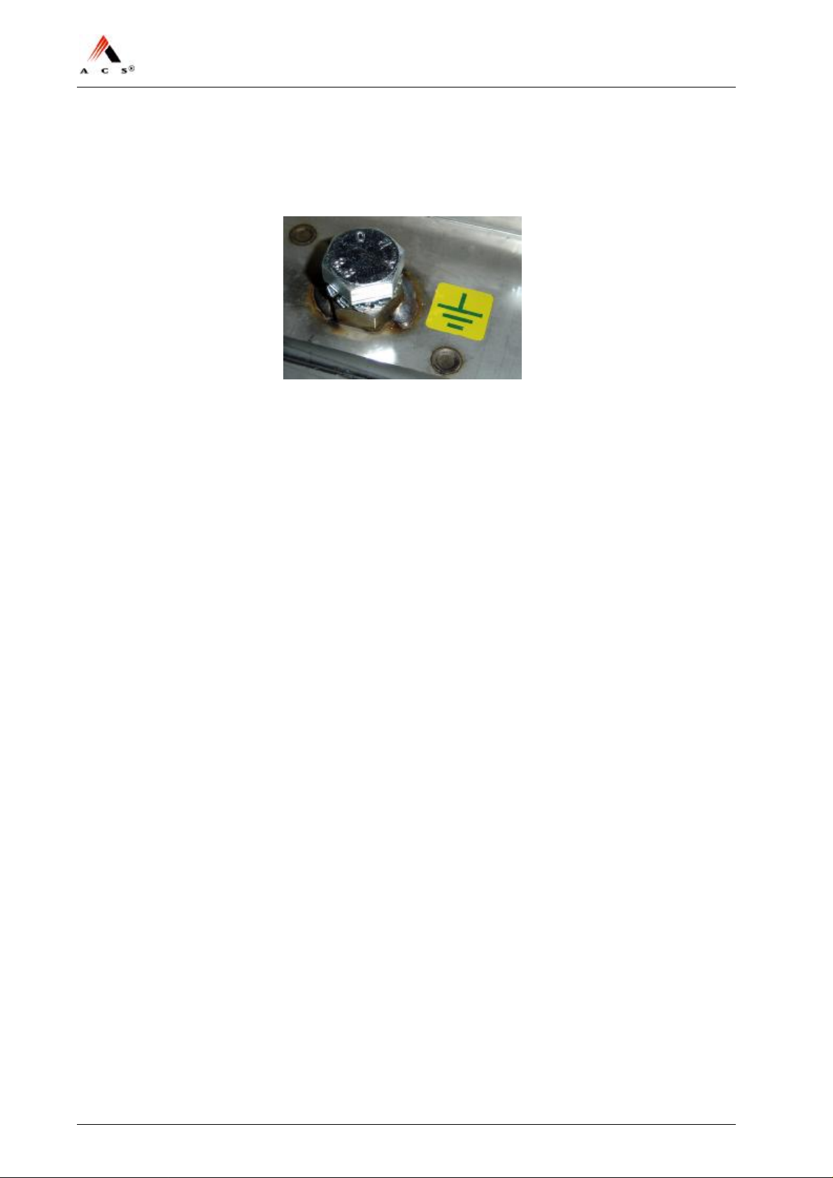
6 Connect the special track ground cable to the intended ground
connection in the TVM:
The TVM is now fully connected to the mains.
End.
26 / 47 Version: 01 ACS Doc-No: 10-000-004-711 - BH - 06 - EN
Page 27
NJT: Expert900 Install. & Initial Setup
4.7 Connecting the TVM to the Network
4.7.1 Network Connection with Shielded Cable
Connection
Procedure
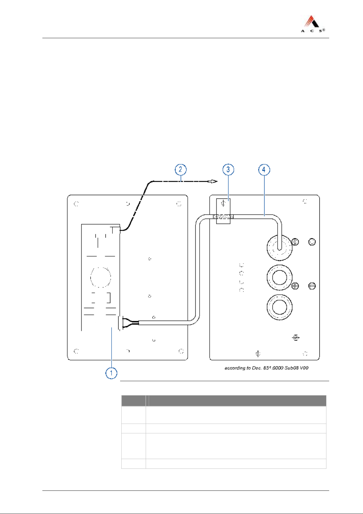
1 Insert the network cable connecter into the open input port of the
modular coupler.
2 Use the recommended cable fastener to provide strain relief.
Figure 7: Network connection with shielded cable connection
Pos.
1 Connector including wiring with max. AWG 26-14
2 To MODEM – dial up
3 Shielded cable fixed with EMC-approved fastening-element
4 Cable-signal: solid conductor or flex cord
ACS Doc-No: 10-000-004-711 - BH - 06 - EN Version: 01 Seite 27 / 47
Description
(e.g. WAGO CageClamp Part No 231-306/026-000
(e.g. 918.0547 for shielded diameter 5mm)
Before fastening remove isolating material down to shield
Page 28
NJT: Expert900 Install. & Initial Setup
End.
4.7.2 Network Connection with Unshielded Cable
Connection
Procedure
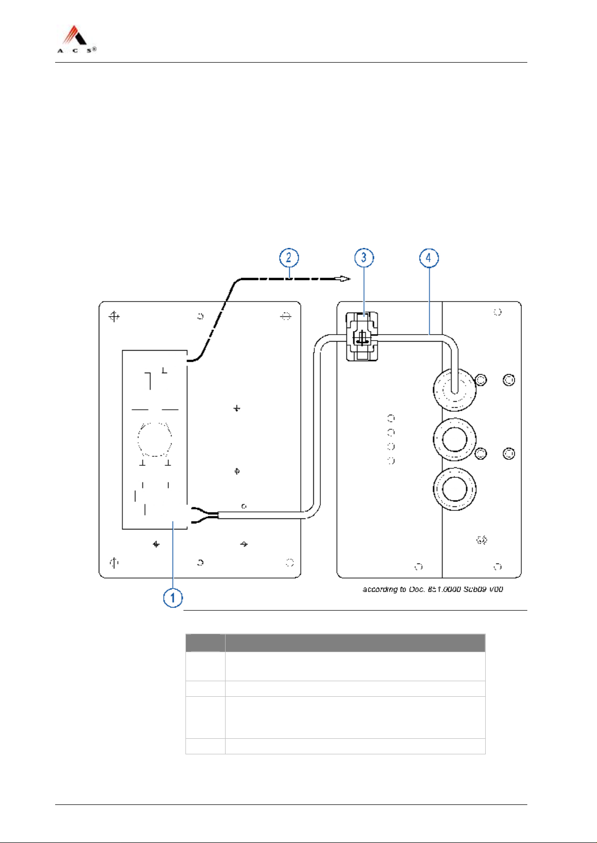
1 Insert the network cable connecter into the open input port of the
modular coupler, see Figure 8.
2 Use the recommended cable fastener to provide strain relief.
Figure 8: Network connection with unshielded cable connection
Pos.
1 Connector including wiring with max. AWG 26-14
2 To MODEM – dial up
3 Cable fastener and mounting plate:
4 Cable-signal: solid conductor or flex cord
28 / 47 Version: 01 ACS Doc-No: 10-000-004-711 - BH - 06 - EN
Description
(e.g. WAGO CageClamp Part No 231-306/026-000
(e.g. 918.0553 type TC-140 Thomas&Belts and
918.0551 type BT1-M-M Panduit)
End.
Page 29

NJT: Expert900 Install. & Initial Setup
5 Initial Start-up
5.1 Overview
Check to make sure that the TVM has been fully installed.
Please note: It is important that the Printer system is initialized first so
that you will be able to print out initialization records for subsequent
modules.
Following are the main steps involved in starting up the TVM for the
first time:
1 Remove packaging material and transport security devices (mainly
paper pads and visible foam inserts, also tape on RS2x coin verifier).
2 Install the software packages.
3 Execute terminal initialization (network parameter, serial number
etc.).
4 Load paper (ticket media).
5 Inspect coin vault, banknote vault and BUCOs.
6 Initialize the modules in following order:
− Printer system
− Coin processing module
− Banknote acceptor
− CTU module (option)
− EFT-PoS Card Processing
7 Initialize the sales application.
End.
5.2 Requirements
• Physical installation of the TVM must be complete; network and
power supply cables must be available and connected.
• Configurated USB Memory Stick containing the software packages
(operation system, sales- and maintenance application).
• You must have a user ID and password.
• You must know the TVM parameters, e.g. network parameters,
station ID etc., see section 5.4.3 starting on page 31.
• You must also know the parameters for the commissioning of the
EFT-PoS card processing, see input-screen on page 47.
ACS Doc-No: 10-000-004-711 - BH - 06 - EN Version: 01 Seite 29 / 47
Page 30

NJT: Expert900 Install. & Initial Setup
• You must have coins on hand in specific denominations for filling the
empty coin drum. (This might be done afterwards from cash handling
agency)
5.3 Special tools
• Door keys (shroud lock, four allen key, half-cylinder lock)
5.4 Starting up the TVM
5.4.1 Remove Packaging Material andTransport Security
Locks
Procedure
1 Open the TVM and remove all packaging material.
2 Remove also the transport security tape on coin verifier (marked with
a big orange sign),
End.
5.4.2 Software Installation
Requirements
• Configured USB memory stick with the correct software packages.
Note
Check how much storage capacity is still available on the USB memory
stick. You should make a backup copy of the “log.txt" file in the
“Scripts” directory and then delete this file from the USB memory stick
after about 10 update installations.
The same applies to the “Backup” directory (delete the directory).
Procedure
1 Open the door of the TVM.
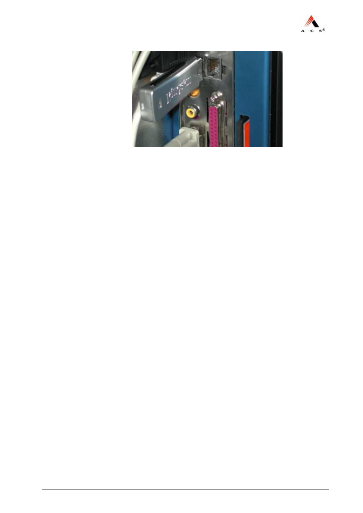
2 Insert the USB memory stick in a free USB port on the side of the
Main Control Unit (MCU):
30 / 47 Version: 01 ACS Doc-No: 10-000-004-711 - BH - 06 - EN
Page 31
NJT: Expert900 Install. & Initial Setup
3 Switch the TVM on.
4 Wait until you hear a repeating audio signal:
When the interval between audio signals is 3 seconds, then the
installation of the software update was successful.
If the interval between audio signals is 1 second, then there was a
problem.
5 Switch off the main switch of the TVM again (this may take several
minutes).
6 Remove the USB memory stick.
7 Switch the TVM back on again. Log in to the maintenance
application. You can now perform the terminal initialization, see next
section 5.4.3 on page 31.
End.
Troubleshooting problems during installation of the software
Send a copy of the file “log.txt” in the “Scripts” directory on the USB
memory stick to the Customer Service department of
ACS Solutions Switzerland Ltd.
5.4.3 Terminal Initialization
Requirements
During the initialization you will be asked to enter the
• Unit number,
• Unit identification,
• Station ID,
• Unit location,
• Arcos parameters,
• Network parameters.
ACS Doc-No: 10-000-004-711 - BH - 06 - EN Version: 01 Seite 31 / 47
Page 32
NJT: Expert900 Install. & Initial Setup
Procedure
Important note:
Make sure to enter the network parameters (maintenance function “Set
Network Parameters”) at the endduring the terminal initialization as the
TVM will reboot with the execution of this function and activate the
parameters.
1 Open the TVM and switch on the mains switch. Login the
maintenance application.
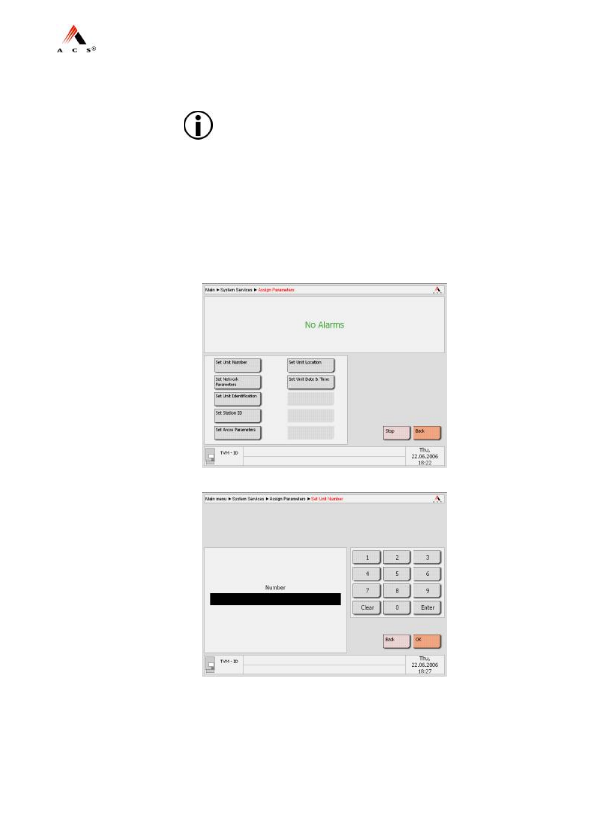
2 Go to “Main” è “System Services” and click on Assign Parameters,
following screen appears:
3 Click on Set Unit Number, following screen appears:
4 Enter the unit number, click Enter and confirm by means of clicking
OK.
32 / 47 Version: 01 ACS Doc-No: 10-000-004-711 - BH - 06 - EN
Page 33
NJT: Expert900 Install. & Initial Setup
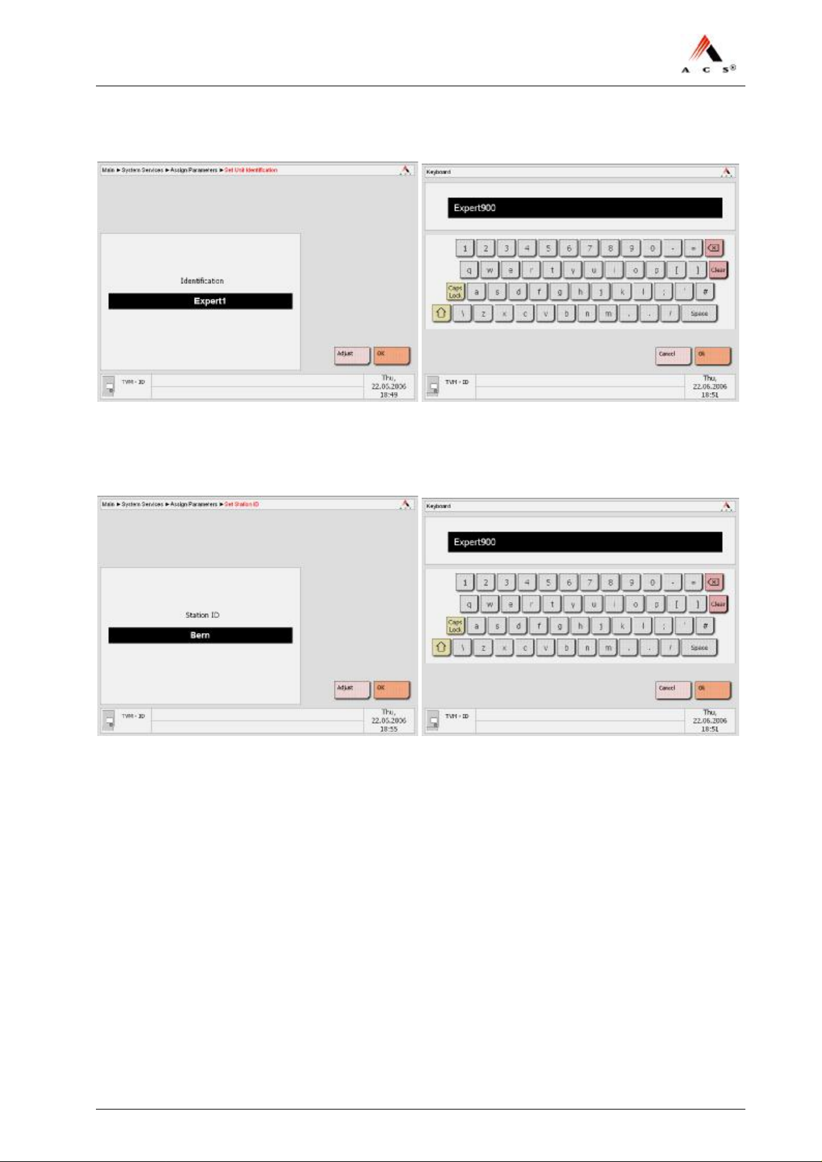
5 Click on Set Unit Identification, following screen appears:
6 Click Adjust for the display of the keyboard. Enter the unit
identification and confirm with OK. (examples are shown above).
7 Click on Set Station ID, following screen appears:
8 Click Adjust for the display of the keyboard. Enter the station ID and
confirm with OK. (examples are shown above).
9 Click Adjust for the display of the keyboard. Enter the ARCOS
Hostname and FTP Server address. Confirm with OK.
ACS Doc-No: 10-000-004-711 - BH - 06 - EN Version: 01 Seite 33 / 47
Page 34
NJT: Expert900 Install. & Initial Setup
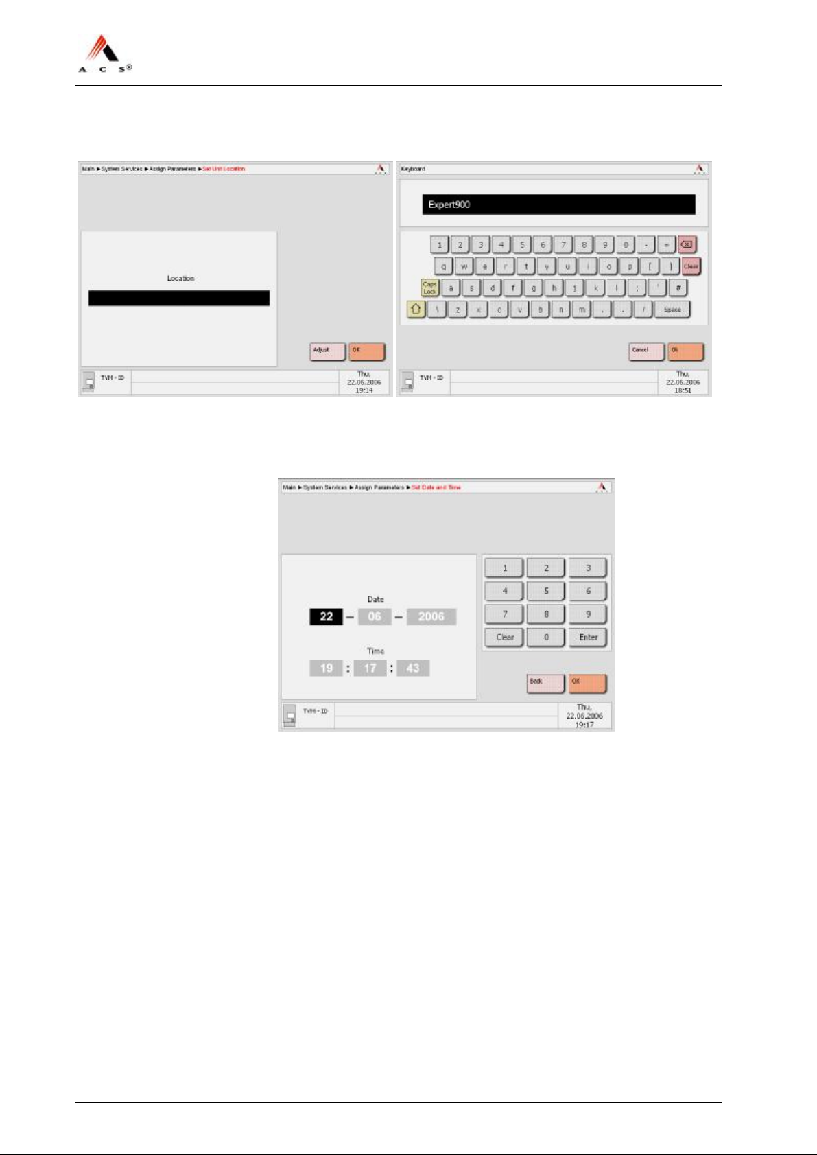
10 Click on Set Unit Location, following screen appears:
11 Click Adjust for the display of the keyboard. Enter the location of the
TVM. Confirm with OK.
12 Click on Set Date and Time, following screen appears:
13 Enter the date and time, clicking Enter changes the input box. Check
your entries and confirm them with OK.
34 / 47 Version: 01 ACS Doc-No: 10-000-004-711 - BH - 06 - EN
Page 35
NJT: Expert900 Install. & Initial Setup
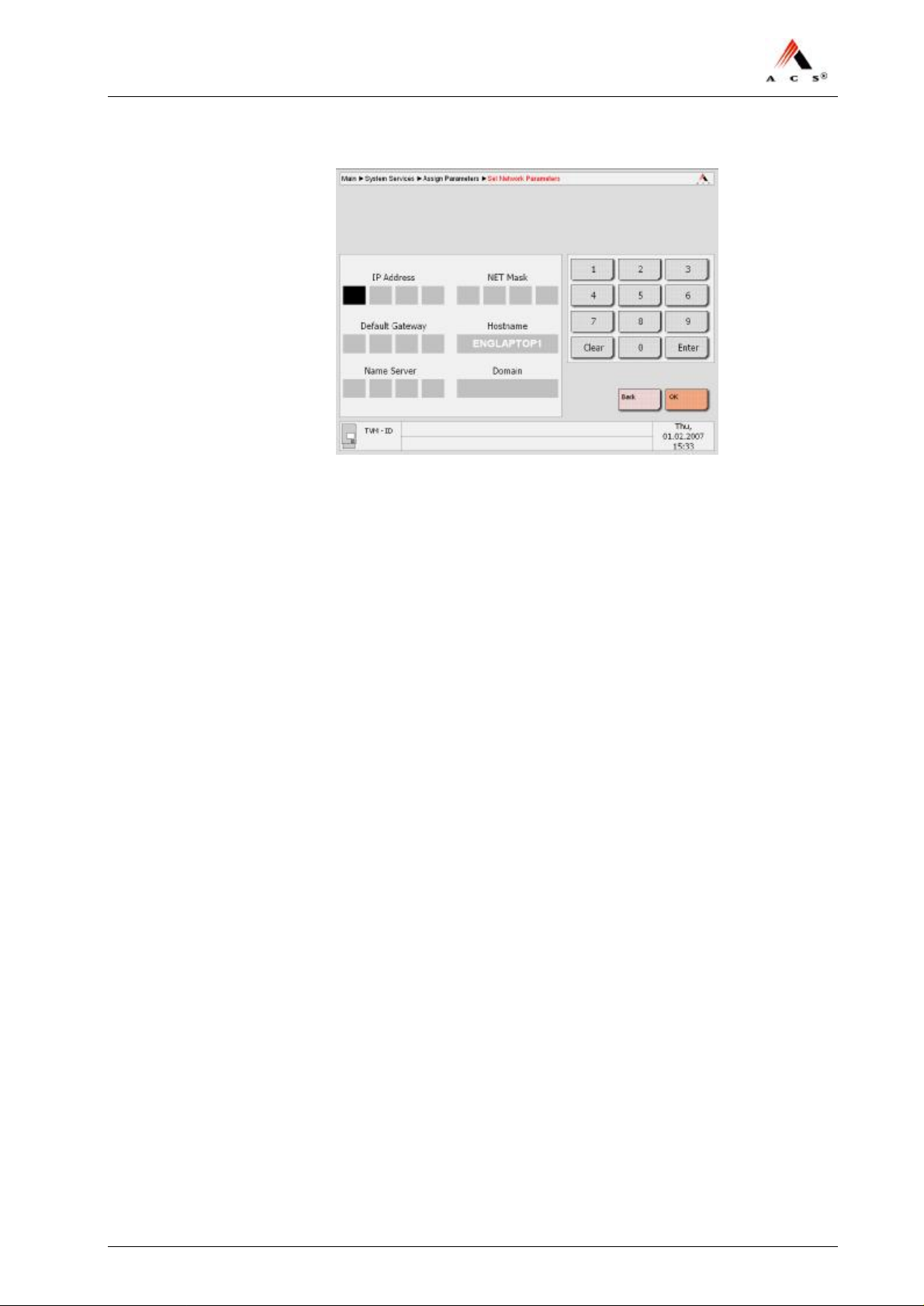
14 Click on Set Network Parameters, following screen appears:
15 Enter the parameters and confirm them with OK. The TVM will
reboot. Wait, until the screen for the login appears again. Login the
maintenance application.
End.
The TVM is now ready for the initialization of the modules (coin
processing, printer, etc.).
ACS Doc-No: 10-000-004-711 - BH - 06 - EN Version: 01 Seite 35 / 47
Page 36

NJT: Expert900 Install. & Initial Setup
5.4.4 Load Paper (Ticket Media)
Refer to document “Routine Jobs”, section “ Refill Paper” in order to
load the paper coils onto the roll holders of the printer system.
5.4.5 Inspecting Coin Vault, Banknote Vault & BUCOs
The initialization of the modules is based on the following assumptions:
• Coin vault and banknote vault are empty and locked into place. If a
vault is not locked into place you can try to lock it in. however, if this
is not possible the vault must be reset by opening its lid and this must
be done by the cash-handling agency. The units come with the cash
vaults installed and do not need any manipulation.
• BUCOs must be full (Capacity, denomination and its filling levels are
preconfigured and must be followed at all times). If BUCOs are not
available at time of initialization inform the cash–handling agency to
install them afterwards. This has no impact on the initialization
procedures (just skip steps referring to BUCOs)
• Coin drums levels can be entered manually but must be known before
initialization. Empty coin drums are installed in the unit and an
initialization is possible without any coins. Refill procedures can be
done by the cash-handling agency after the initialization. (If this is
required skip steps that refer to coin re-fill functions)
Procedure
1 Check to make sure that the coin vault is in the coin handling system
and properly locked in. (coin vault is normally empty and needs to be
checked on a reinstallation only).
2 Check to make sure that the banknote vault is in the banknote
acceptor and, if so, that it is empty and properly locked into place.
(banknote vault is normally empty and needs to be checked on a
reinstallation only).
3 Load the full BUCOs into the coin handling system, see also “Routine
Jobs”, section “Replace Auxiliary Coin Storage Unit (BUCO)” for
further information. Do not use empty BUCOs since the TVM
automatically assumes full BUCOs. If you have empty BUCOs only
or are not sure that the BUCO is full disconnect the BUCO and
inform the cash-handling agency.
End.
36 / 47 Version: 01 ACS Doc-No: 10-000-004-711 - BH - 06 - EN
Page 37
NJT: Expert900 Install. & Initial Setup
5.4.6 Initializing the Printer System
Procedure
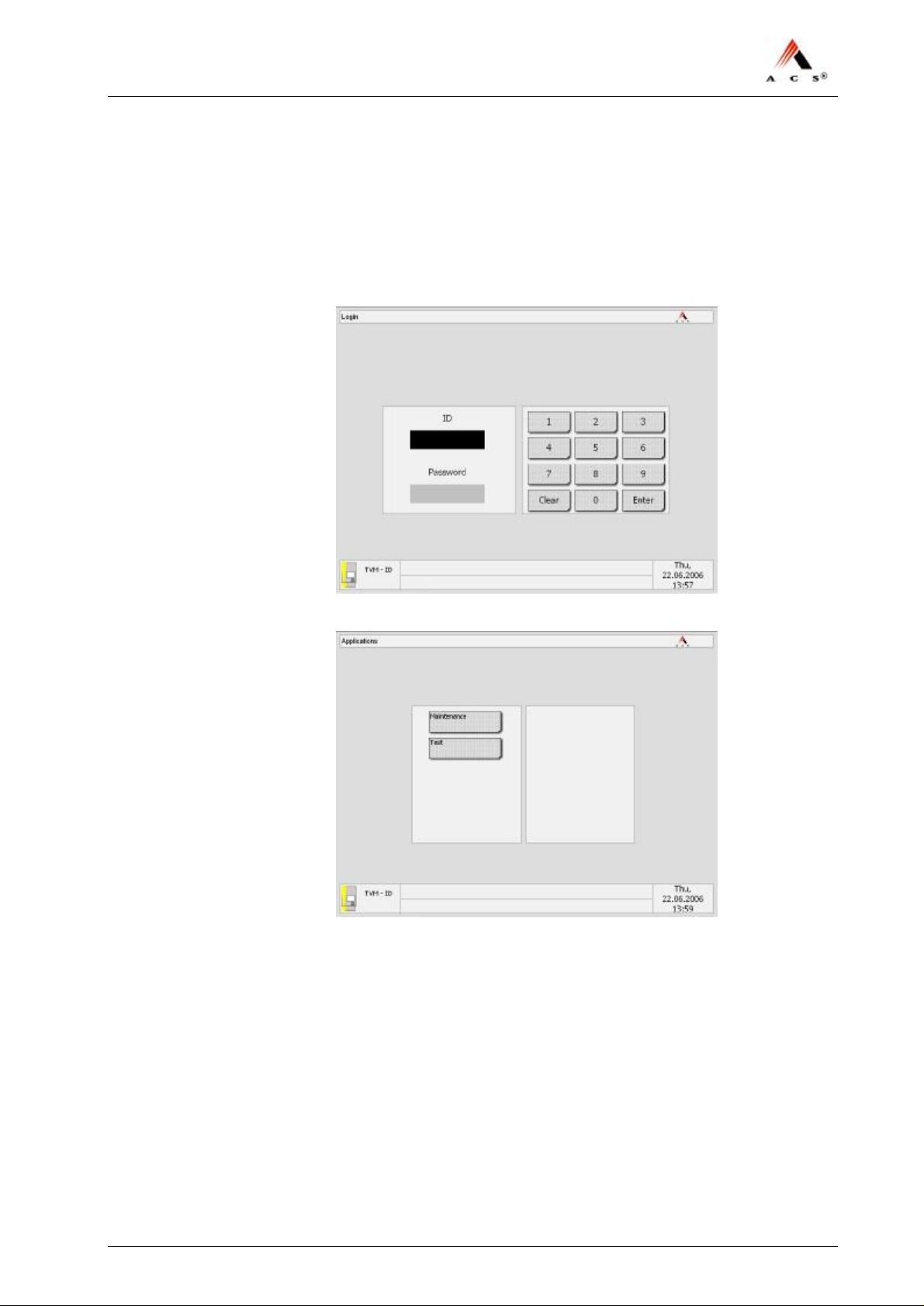
1 Open the door of the TVM and switch it on. Wait until the computer
has booted up. The screen for logging into the service application
appears:
2 Log in to the service application. The applications menu appears:
3 Select the Maintenance application. The main menu appears:
ACS Doc-No: 10-000-004-711 - BH - 06 - EN Version: 01 Seite 37 / 47
Page 38
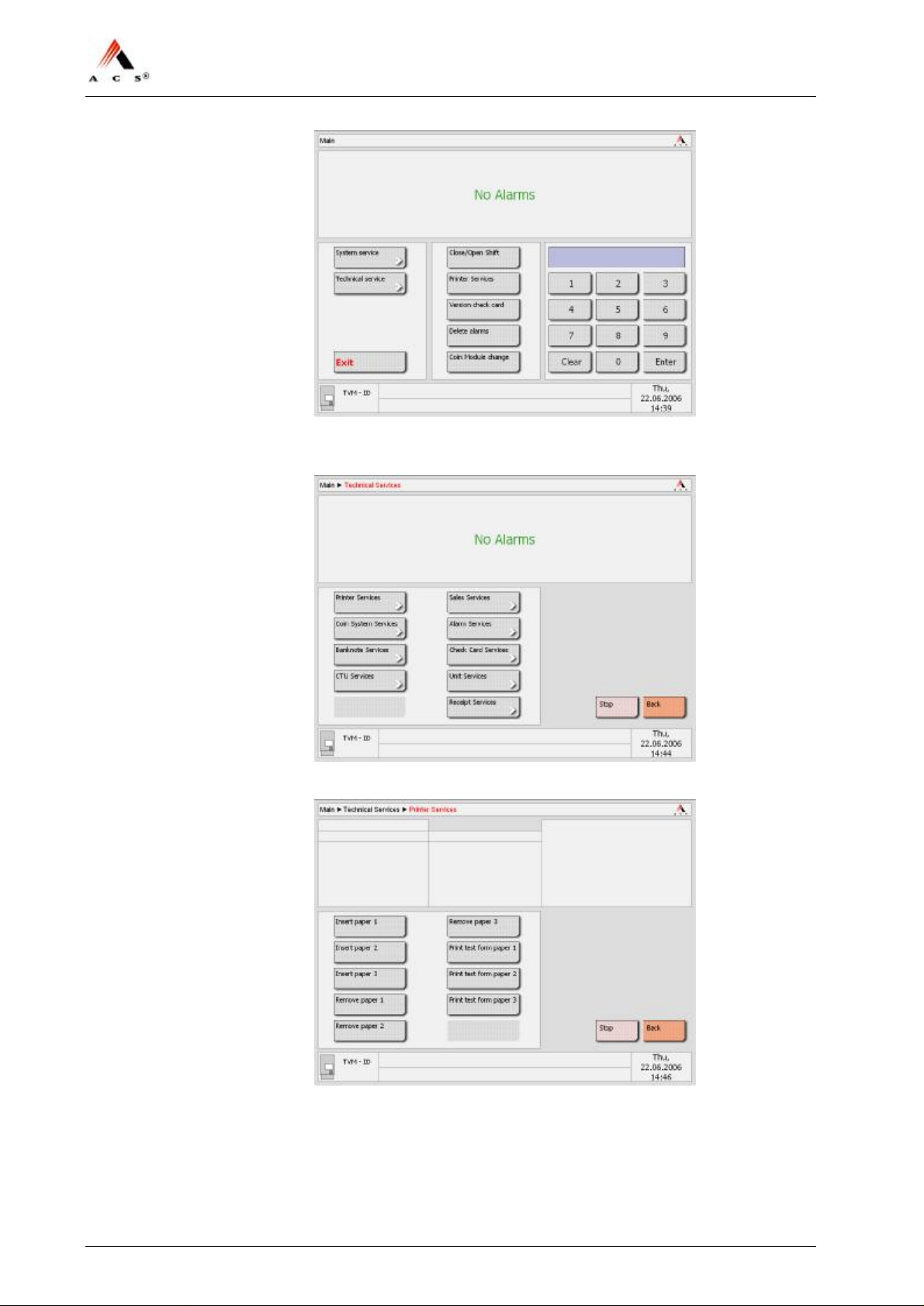
NJT: Expert900 Install. & Initial Setup
4 Select Technical Services from the main menu. The following screen
appears:
5 Select the Printer Services submenu. The following screen appears:
6 Select Insert paper 1. The following screen appears:
38 / 47 Version: 01 ACS Doc-No: 10-000-004-711 - BH - 06 - EN
Page 39
NJT: Expert900 Install. & Initial Setup
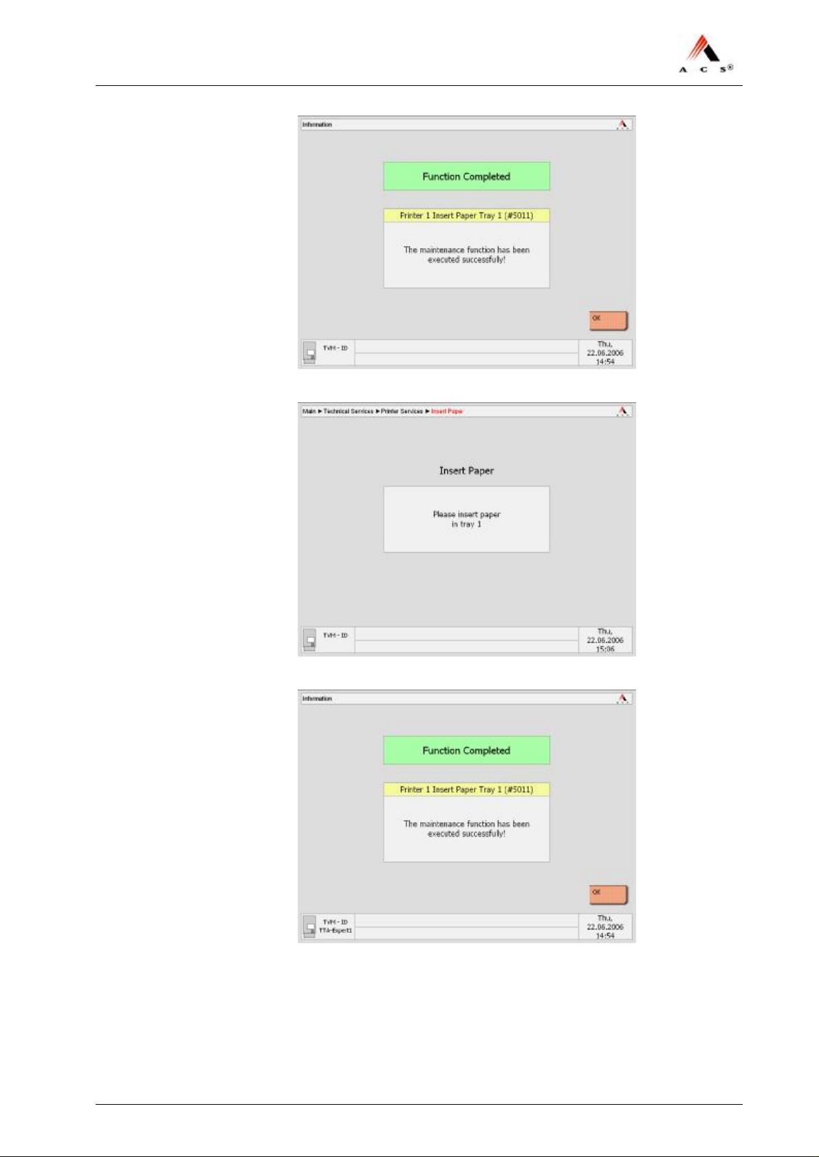
7 Confirm by selecting Yes .
8 Insert the paper in the front tray 1. Then, this screen appears:
9 Confirm by selecting OK. Accept the automatically printed test ticket
or go back to “Printer Services” and click on Print test form paper
1. Accept the test ticket.
10 Go back to “Printer Services” and repeat the procedure for the other
paper path. End.
ACS Doc-No: 10-000-004-711 - BH - 06 - EN Version: 01 Seite 39 / 47
Page 40
NJT: Expert900 Install. & Initial Setup
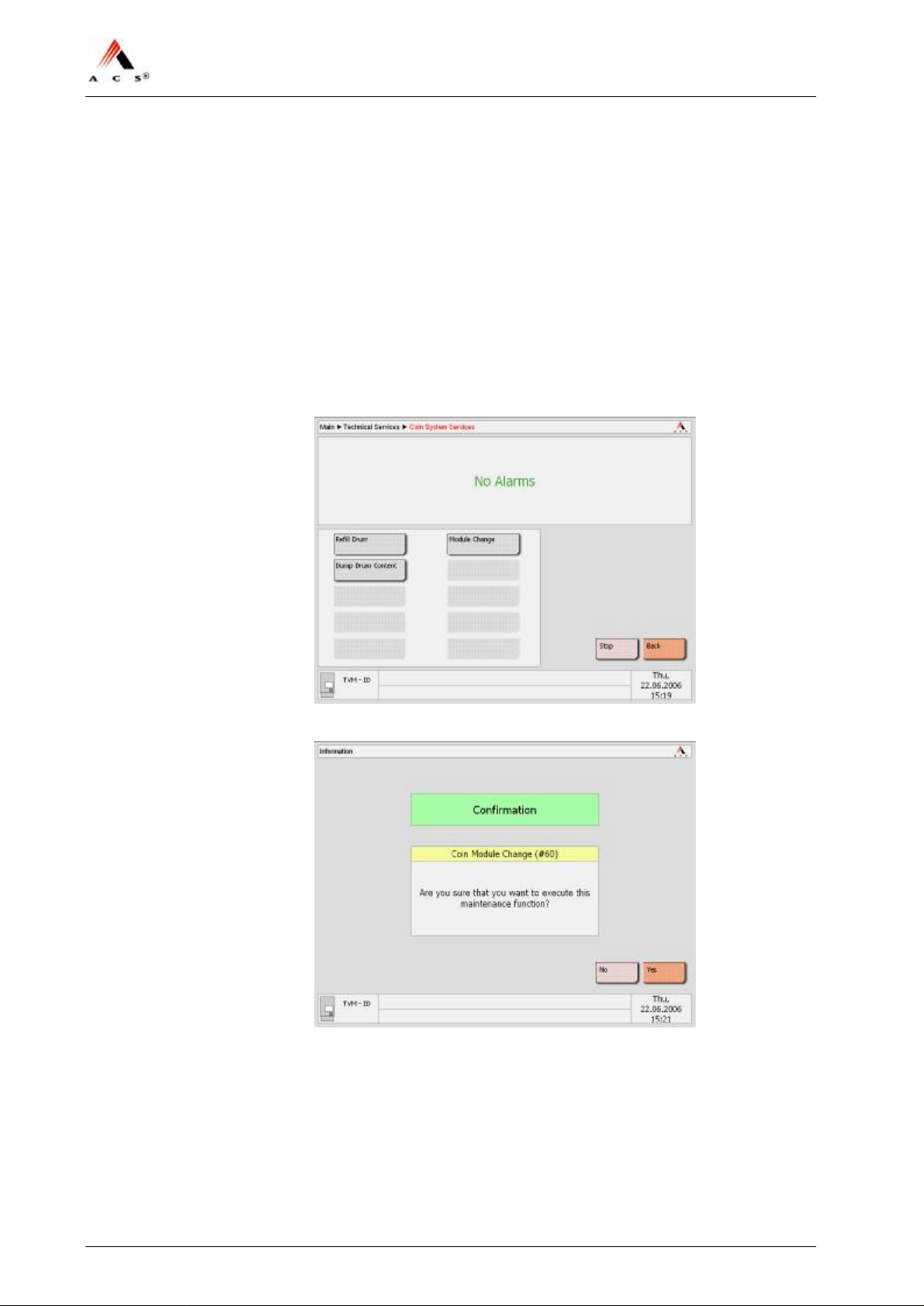
5.4.7 Initializing the Coin Processing System
Requirements
• BUCOs are properly installed and connected,
• Coin vault is properly locked in,
If necessary, go back to section “Inspecting Coin Vault, Banknote Vault
& BUCOs” on page 36 to check the requirements for the initialization.
Procedure
1 Select the Coin System Services in the menu „Technical Services“.
The following screen appears:
2 Select Module Change. The following screen appears:
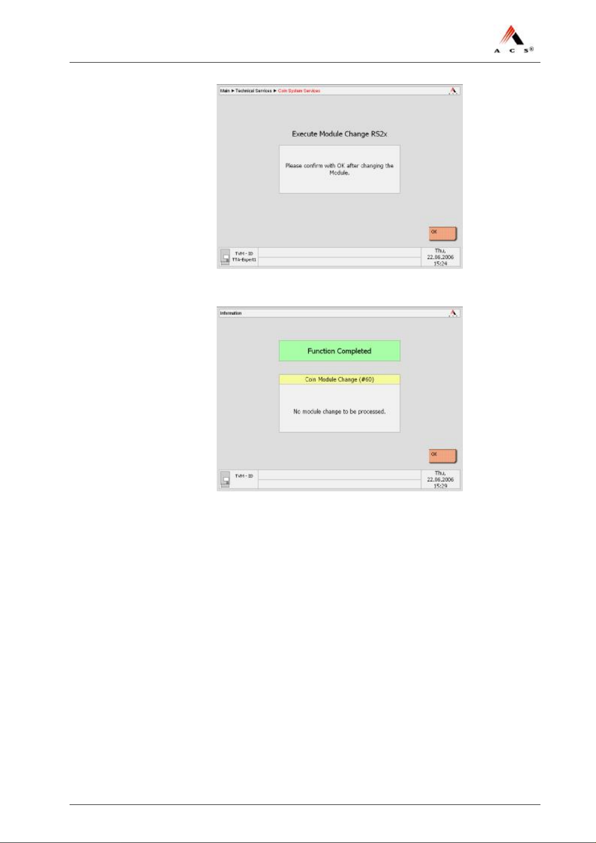
3 Confirm by selecting Yes.
40 / 47 Version: 01 ACS Doc-No: 10-000-004-711 - BH - 06 - EN
Page 41
NJT: Expert900 Install. & Initial Setup
4 Confirm by selecting OK.
5 Confirm by selecting OK and accept the printed receipts.
If the receipts are not printed automatically, print them by means of
the maintenance function “Show not printed receipt”, quick code
number 80630.
5.4.8 Fill the Coin Drums of the Coin Processing System
Requirements
Coins in specific denominations.
Procedure
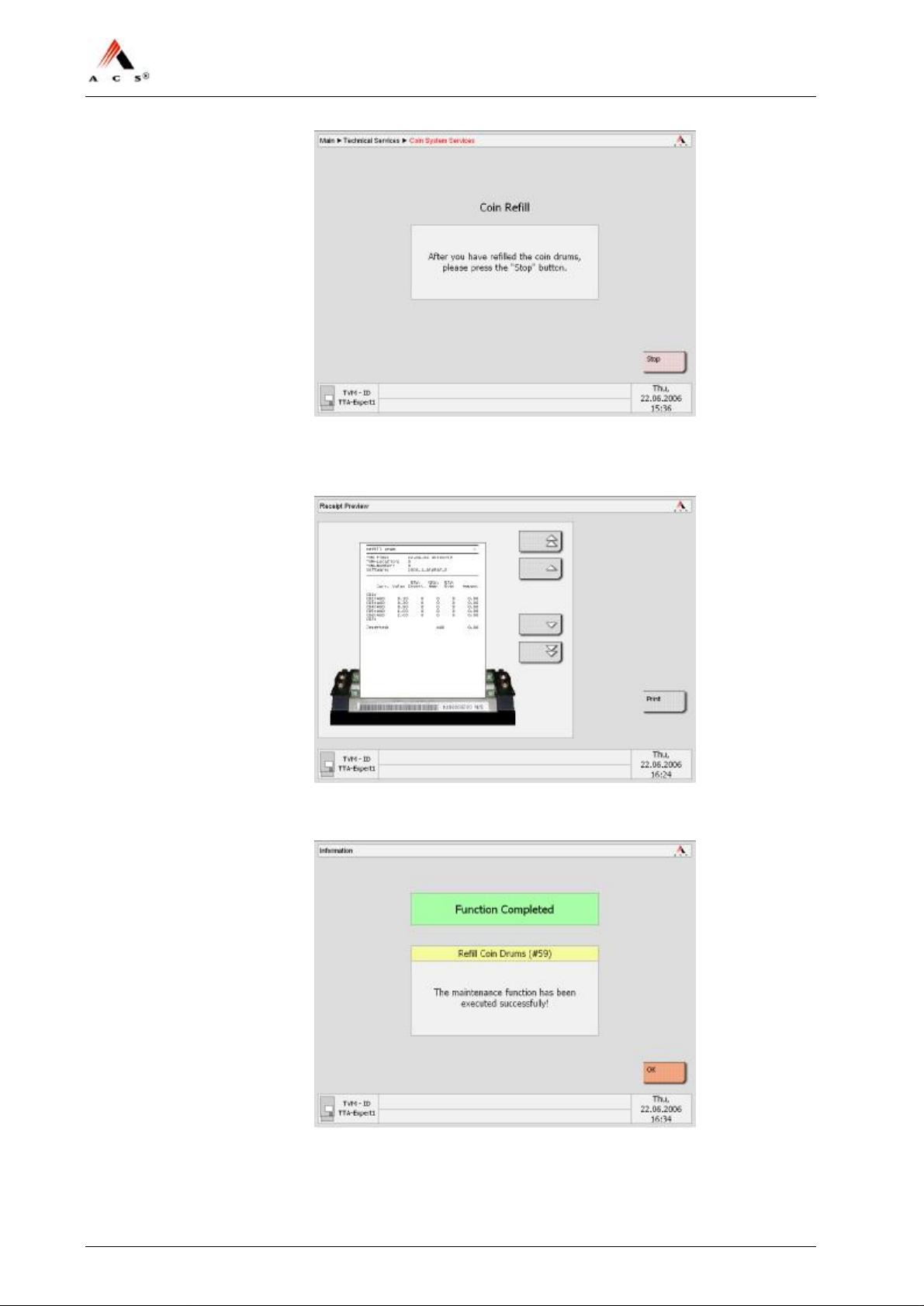
1 Select Refill Drums in the menu „Coin System Services“. The „Coin
Refill“ screen appears:
ACS Doc-No: 10-000-004-711 - BH - 06 - EN Version: 01 Seite 41 / 47
Page 42
NJT: Expert900 Install. & Initial Setup
2 Put in the prepared change (any order is possible), when finished,
press Stop. You will be asked to print out the numbered receipt
declaring the actual content of the coin drums:
3 Press Print, take it out of the change tray and keep the receipt in safe
custody. Then this confirmation appears:
4 Press OK.
The initialization of the coin processing system is fully accomplished.
42 / 47 Version: 01 ACS Doc-No: 10-000-004-711 - BH - 06 - EN
Page 43

NJT: Expert900 Install. & Initial Setup
5 Return to the menu „Technical Services“ by clicking Back.
End.
ACS Doc-No: 10-000-004-711 - BH - 06 - EN Version: 01 Seite 43 / 47
Page 44
NJT: Expert900 Install. & Initial Setup
5.4.9 Initializing the Banknote Verifier
Requirements
If necessary, go back to section “Inspecting Coin Vault, Banknote Vault
& BUCOs” on page 36 to check the requirements for the initialization.
Procedure
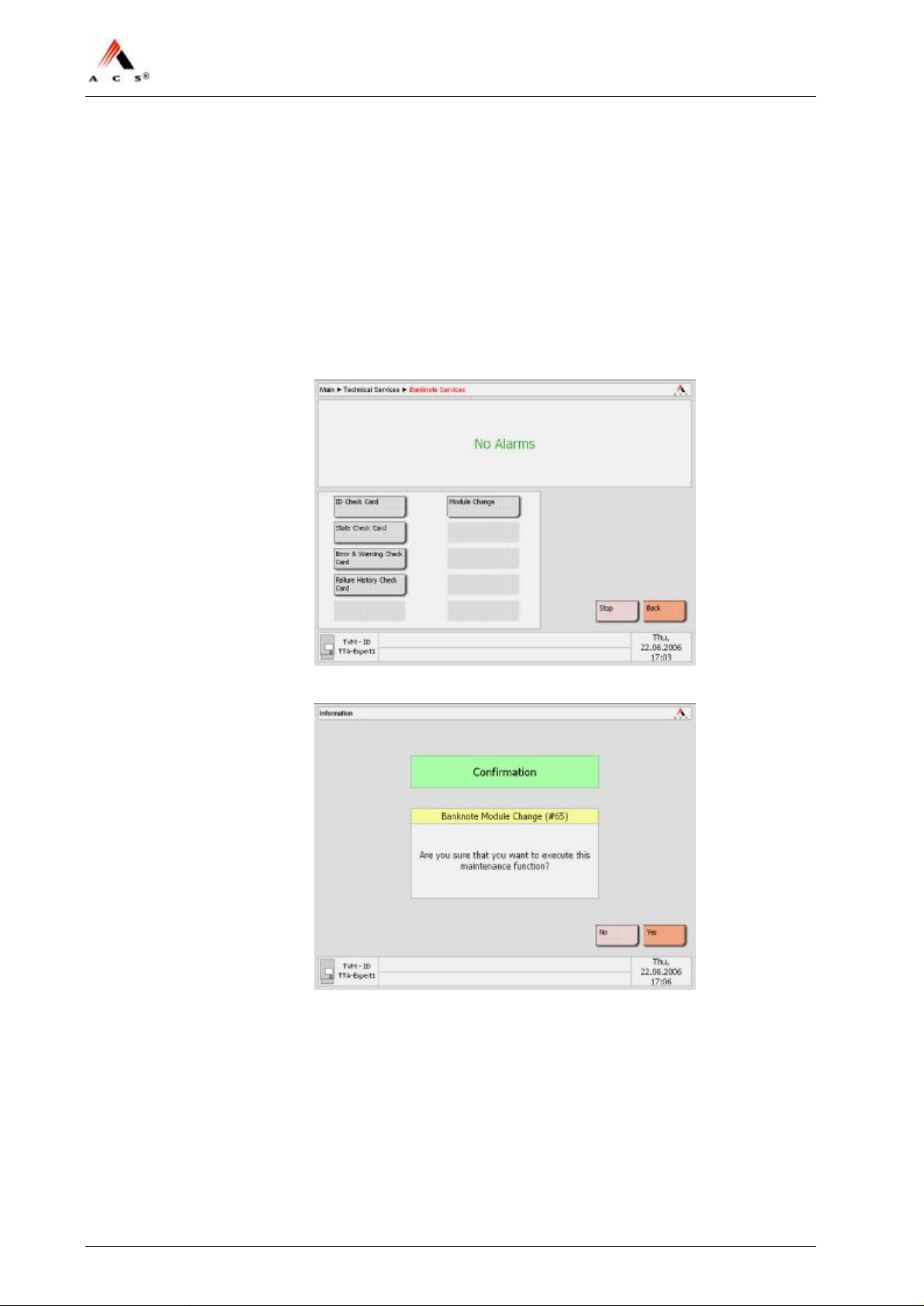
1 Select the Banknote Services in the menu „Technical Services“ This
screen appears:
2 Select the Module Change. The following screen appears:
3 Confirm by clicking Yes .
44 / 47 Version: 01 ACS Doc-No: 10-000-004-711 - BH - 06 - EN
Page 45
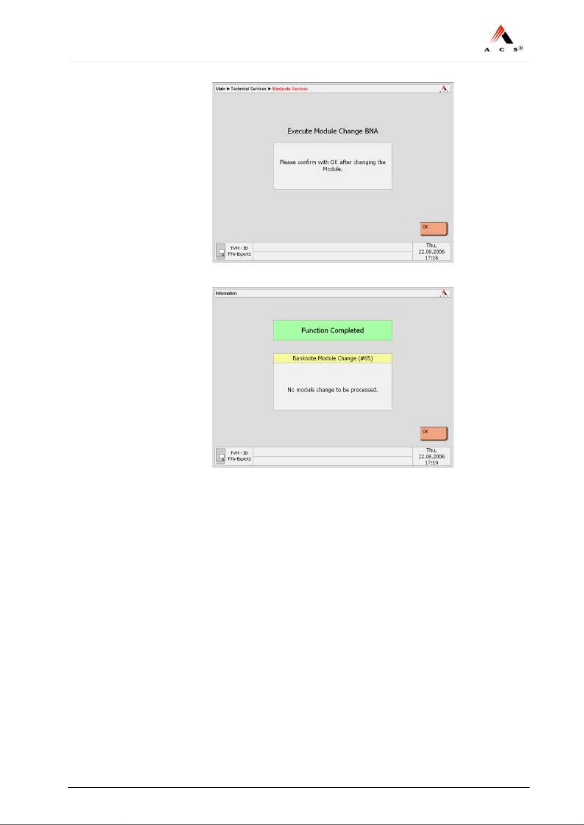
NJT: Expert900 Install. & Initial Setup
4 Confirm by clicking OK and wait on the following screen:
5 Press OK.
The initialization of the banknote acceptor is fully accomplished.
ACS Doc-No: 10-000-004-711 - BH - 06 - EN Version: 01 Seite 45 / 47
Page 46
NJT: Expert900 Install. & Initial Setup
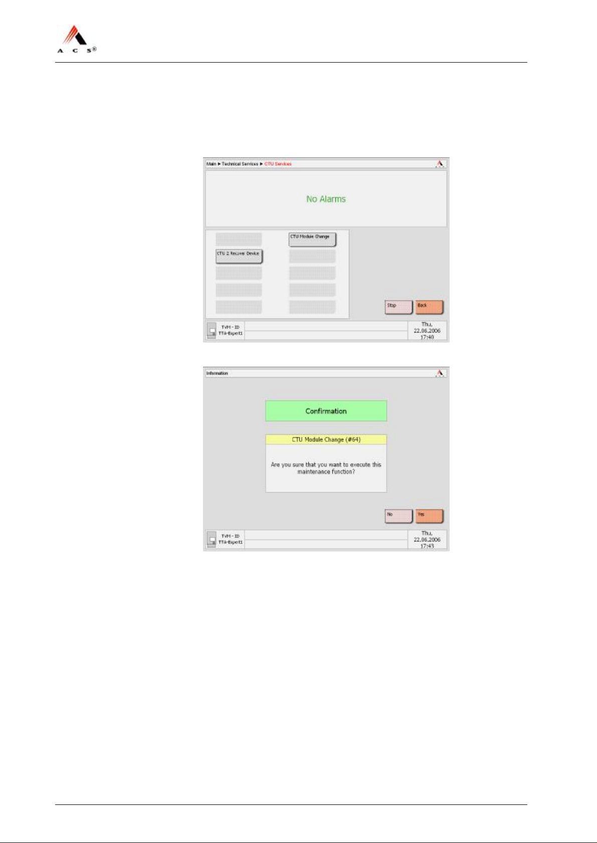
5.4.10 Initializing the Card Handling Module (option)
1 Select the CTU Services in the menu „Technical Services“. The
following screen appears:
2 Select CTU Module Change and a confirmation screen appears:
3 Confirm by clicking Yes .
4 Confirm by selecting OK.
5 Press OK.
The initialization of the CTU-Module is fully accomplished.
6 Do the same procedure for each CTU-Module (if necessary).
46 / 47 Version: 01 ACS Doc-No: 10-000-004-711 - BH - 06 - EN
Page 47
NJT: Expert900 Install. & Initial Setup
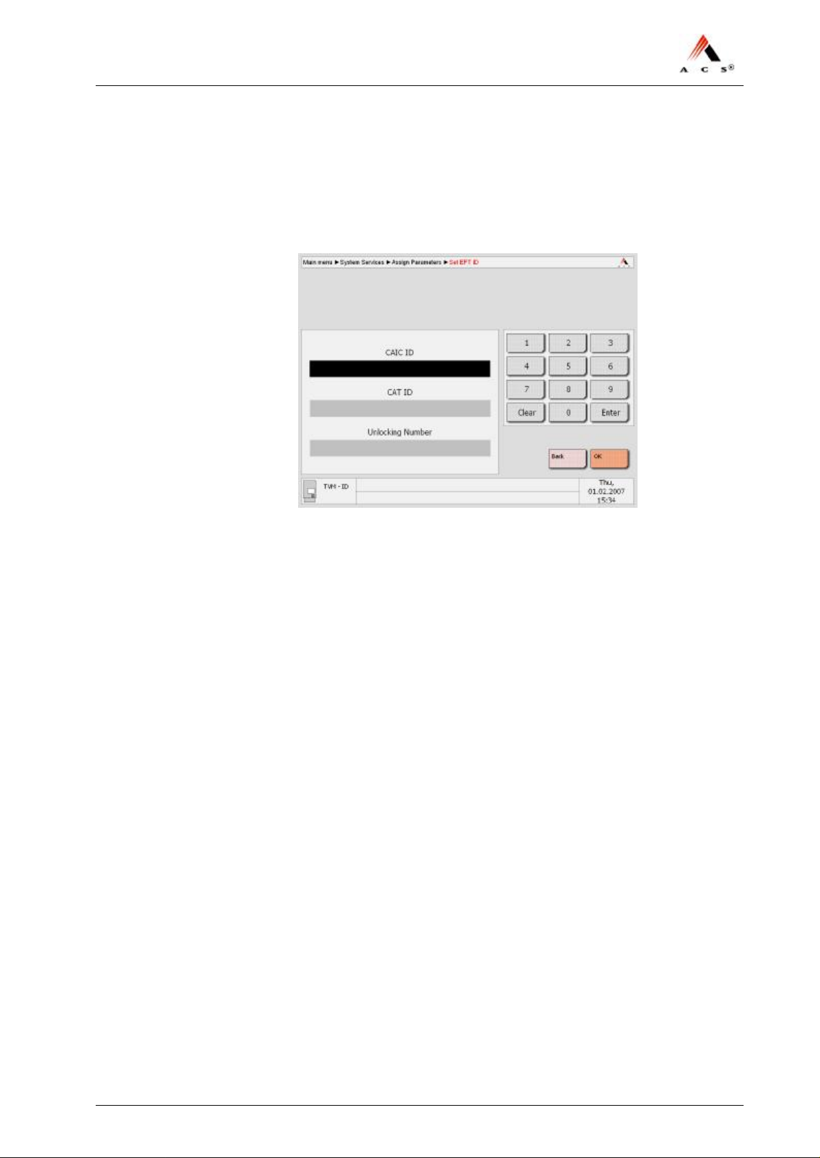
5.4.11 Commissioning of the EFT-PoS Card Processing
Procedure
1 Go to “Main” è “System Services” è “Assign Parameters“ and
click on Set EFT ID. The following screen appears:
2 Enter the parameters and confirm them with OK.
End.
5.4.12 Initializing the Sales Application
Procedure
1 Return to the main menu of the maintenance application.
2 Close the door; this will automatically initiate the sales application.
The TVM is now ready to use.
3 Complete the Installation protocol, have it signed and file it for
reference.
ACS Doc-No: 10-000-004-711 - BH - 06 - EN Version: 01 Seite 47 / 47
 Loading...