

Page 1
AET65
Smart Card Reader
Reference Manual
Subject to change without prior notice
info@acs.com.hk
www.acs.com.hk
Page 2

Table of Contents
1.0. ...............................................................................................................4 Introduction
.......................................................................................5 AET65 Smart Card Reader
2.0.
3.0.
.....................................................................................................................6 Features
4.0.
..................................................................................................7 Smart Card Support
4.1. ............................................................................................................................7 MCU Cards
5.0. .................................................................................................8 Smart Card Interface
5.1. ....................................................................................8 Smart Card Power Supply VCC (C1)
............................................................................................8 Programming Voltage VPP (C6)
5.2.
..............................................................................................................8 Card Type Selection
5.3.
.............................................................................8 Interface for Microcontroller-based Cards
5.4.
.........................................................................................................8 Card Tearing Protection
5.5.
6.0. ............................................................................................................9 Power Supply
6.1. .............................................................................................................................9 Status LED
7.0. ...........................................................................................................10 USB Interface
7.1. ................................................................................................10 Communication Parameters
.............................................................................................................................10 Endpoints
7.2.
8.0. .......................................................................................11 Communication Protocol
8.1. .........................................................................................11 AET65 Communication Protocol
....................................................................................................11 Command to AET65
8.1.1.
................................................................................................11 Response from AET65
8.1.2.
..................................................................................................12 Card Status Message
8.1.3.
9.0. ..................................................................................................13 AET65 Commands
9.1. ..............................................................................................................13 Control Commands
........................................................................................................13 GET_ACR_STAT
9.1.1.
..............................................................................................14 SELECT_CARD_TYPE
9.1.2.
.............................................................................................................14 SET_OPTION
9.1.3.
........................................................................................................15 SET_CARD_PPS
9.1.4.
...................................................................................................15 SET_READER_PPS
9.1.5.
........................................................................................................16 MCU Card Commands
9.2.
.........................................................................16 RESET_WITH_5_VOLTS_DEFAULT
9.2.1.
.......................................................................16 RESET_WITH_SPECIFIC_VOLTAGE
9.2.2.
.............................................................................................................17 POWER_OFF
9.2.3.
..............................................................................................17 EXCHANGE_TPDU_T0
9.2.4.
..............................................................................................18 EXCHANGE_TPDU_T1
9.2.5.
Appendix A. ..........................................................................................................19 AET65
Appendix A.1.
Appendix A.2.
............................................................................19 Supported Card Types
.........................................................................19 Response Status Codes
Figures
Figure 1. ..........................................................................................4AET65 System Block Diagram
AET65 Reference Manual
Document Title Here
Document Title Here
Version 1.00
Document Title Here
Page 2 of 19
info@acs.com.hk
www.acs.com.hk
Page 3

Tables
Table 1. ..........................................................................................................10USB Interface Wiring
AET65 Reference Manual
Document Title Here
Document Title Here
Version 1.00
Document Title Here
Page 3 of 19
info@acs.com.hk
www.acs.com.hk
Page 4
1.0. Introduction
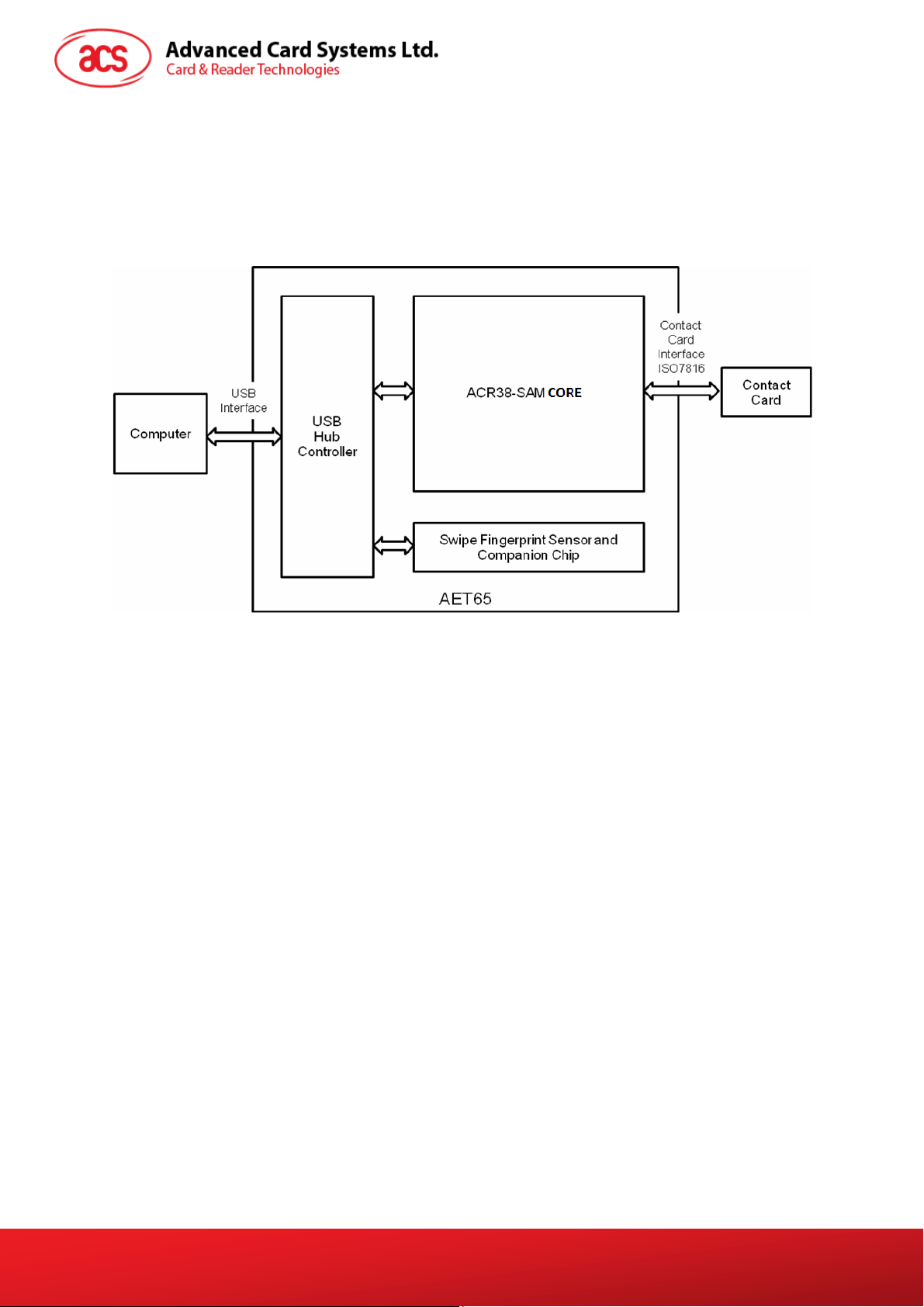
The AET65 is a composite device, consisting of the core of ACS’ ACR38-SAM smart card reader and
UPEK’s swipe fingerprint sensor. The smart card reader and the fingerprint sensor can be used
independently, but combining the two technologies provide a higher level of security in applications.
The AET65’s system diagram is shown below:
Figure 1. AET65 System Block Diagram
The purpose of this document is to describe the architecture and interface of AET65’s smart card
reader module, which is based on the ACR38-SAM core. For information on the architecture and
programming interface of the fingerprint module, please refer to the AET65 Fingerprint Reader
Application Programming Interface document (API_AET65_v1.0).
AET65 Reference Manual
Document Title Here
Document Title Here
Version 1.00
Document Title Here
Page 4 of 19
info@acs.com.hk
www.acs.com.hk
Page 5

2.0. AET65 Smart Card Reader
The AET65 Smart Card Reader acts as an interface for the communication between a computer (for
example, a PC) and a smart card. Different types of smart cards have different commands and
different communication protocols which prevents, in most cases the direct communication between a
smart card and a computer. The AET65 Smart Card Reader is based on the ACR38-SAM core which
establishes a uniform interface from the computer to the smart card for a wide variety of cards. By
taking care of the card specific particulars, it releases the computer software programmer from getting
involved with the technical details of the smart card operation, which are not relevant in many cases of
the implementation of smart card system.
Note: Although the AET65 Smart Card Reader is a true card reader/writer as it can read and write
data from and to smart cards. The terms card reader or reader will be used indifferently to refer to
the AET65. These designations are commonly used for this kind of devices.
AET65 Reference Manual
Document Title Here
Document Title Here
Version 1.00
Document Title Here
Page 5 of 19
info@acs.com.hk
www.acs.com.hk
Page 6

3.0. Features
The following are the features of the AET65 Smart Card Reader:
1. PS/SC
2. WHQL Certified Drivers
3. CE and FCC
4. RoHS
5. ISO 7816 (Class A, B, C)
6. MCU Card Support (T=0, T=1)
7. USB Full-Speed
8. Short Circuit Protection
AET65 Reference Manual
Document Title Here
Document Title Here
Version 1.00
Document Title Here
Page 6 of 19
info@acs.com.hk
www.acs.com.hk
Page 7

4.0. Smart Card Support
4.1. MCU Cards
The AET65 Smart Card Reader is a PC/SC compliant smart card reader that supports ISO 7816 5 V,
3 V and 1.8 V (Class A, B, and C) smart cards. The AET65 also works with MCU cards following
either the T=0 and T=1 protocol.
AET65 Reference Manual
Document Title Here
Document Title Here
Version 1.00
Document Title Here
Page 7 of 19
info@acs.com.hk
www.acs.com.hk
Page 8

5.0. Smart Card Interface
The interface between the AET65 and the inserted smart card follows the specifications of ISO7816-3
with certain restrictions or enhancements to increase the practical functionality of the AET65.
5.1. Smart Card Power Supply VCC (C1)
The current consumption of the inserted card must not be higher than 50 mA.
5.2. Programming Voltage VPP (C6)
According to ISO 7816-3, the smart card contact C6 (VPP) supplies the programming voltage to the
smart card. Since all common smart cards in the market are EEPROM-based and do not require the
provision of an external programming voltage, the contact C6 (VPP) has been implemented as a
normal control signal in the AET65. The electrical specifications of this contact are identical to those of
the signal RST (at contact C2).
5.3. Card Type Selection
The controlling PC has to always select the card type through the proper command sent to the AET65
prior to activating the inserted card. .
For MCU-based cards, the reader allows to select the preferred protocol, T=0 or T=1. However, this
selection is only accepted and carried out by the reader through the PPS when the card inserted in
the reader supports both protocol types. Whenever an MCU-based card supports only one protocol
type, T=0 or
selected by the application.
T=1, the reader automatically uses that protocol type, regardless of the protocol type
5.4. Interface for Microcontroller-based Cards
For microcontroller-based smart cards, only the contacts C1 (VCC), C2 (RST), C3 (CLK), C5 (GND)
and C7 (I/O) are used. A frequency of 4 MHz is applied to the CLK signal (C3).
5.5. Card Tearing Protection
The AET65 provides a mechanism to protect the inserted card when it is suddenly withdrawn while it
is powered up. The power supply to the card and the signal lines between the AET65 and the card is
immediately deactivated when the card is being removed. As a general rule however, to avoid any
electrical damage, a card should only be removed from the reader while it is powered down.
Note: The AET65 does never by itself switch on the power supply to the inserted card. This must
explicitly be done by the controlling computer through the proper command sent to the reader.
AET65 Reference Manual
Document Title Here
Document Title Here
Version 1.00
Document Title Here
Page 8 of 19
info@acs.com.hk
www.acs.com.hk
Page 9

6.0. Power Supply
The AET65 requires a voltage of 5 V DC, 100 mA regulated power supply. The AET65 Smart Card
Reader gets power supply from a PC (through the cable supplied along with each type of reader).
6.1. Status LED
The Green LED around the card slot indicates the activation status of the smart card interface:
ON
Indicates that the power supply to the smart card is switched on, i.e., the smart card is
activated.
OFF
Indicates that the power supply to the smart card is switched off, i.e. the smart card has not
been inserted, or the smart card has not been powered up (if it is inserted)
AET65 Reference Manual
Document Title Here
Document Title Here
Version 1.00
Document Title Here
Page 9 of 19
info@acs.com.hk
www.acs.com.hk
Page 10

7.0. USB Interface
The AET65 is connected to a computer through a USB following the USB standard.
7.1. Communication Parameters
The AET65 is connected to a computer through USB as specified in the USB Specification 2.0. The
AET65 is working in full speed mode, i.e. 12 Mbps.
Pin Signal Function
1 V
2 D3 D+
4 GND
Note: In order for the AET65 to function properly through USB interface, the ACS PC/SC
Device Driver has to be installed.
BUS
+5 V power supply for the reader
Differential signal transmits data between AET65 and PC.
Differential signal transmits data between AET65 and PC.
Reference voltage level for power supply
Table 1. USB Interface Wiring
7.2. Endpoints
The AET65 uses the following endpoints to communicate with the host computer:
Control Endpoint For setup and control purposes
Bulk OUT For command to be sent from host to AET65 (data packet size is 64 bytes)
Bulk IN For response to be sent from AET65 to host (data packet size is 64 bytes)
Interrupt IN For card status message to be sent from AET65 to host (data packet size is 8
bytes)
Page 10 of 19
AET65 Reference Manual
Document Title Here
Document Title Here
Version 1.00
Document Title Here
info@acs.com.hk
www.acs.com.hk
Page 11

8.0. Communication Protocol
8.1. AET65 Communication Protocol
During normal operation, the AET65 acts as a slave device with regard to the communication between
a computer and the reader. The communication is carried out in the form of successive commandresponse exchanges. The computer transmits a command to the reader and receives a response
from the reader after the command has been executed. A new command can be transmitted to the
AET65 only after the response to the previous command has been received.
There are two cases where the reader transmits data without having received a command from the
computer namely, the Reset Message and the Card Status Message.
8.1.1. Command to AET65
A command consists of six protocol bytes and a variable number of data bytes with the following
structure:
Byte 1 2 3 4 5 ... N+4 (N>0)
Header Instruction Data Length = N Data
01H
Header Always 01H to indicate the start of a command.
Instruction The instruction code of the command to be carried out by the AET65.
Data Length Number of subsequent data bytes, and is encoded in 2 bytes. The first byte
(MSB) and second byte (LSB) represent data length N.
Data Data contents of the command.
For a READ command, for example, the data bytes would specify the start
address and the number of bytes to be read. For a WRITE command, the
data bytes would specify the start address and the data to be written to the
card.
The data bytes can represent values to be written to a card and/or command
parameters such as an address, a counter, etc.
Note: Commands are sent from host computer to AET65 through the BULK OUT endpoint.
Data
Length N
8.1.2. Response from AET65
The response from the AET65 to any command depends on whether the command has been
received by the reader without error (e.g., checksum error).
The response by the AET65 to a correctly received command consists of three protocol bytes, two
status bytes and a variable number of data bytes with the following structure:
Header Always 01H to indicate the start of the response.
Status Indicates the command execution status:
AET65 Reference Manual
Document Title Here
Document Title Here
Version 1.00
Byte 1 2 3 4 5 ... N+4 (N>0)
Header Status Data Length = N Data
01H
Data Length
N
Document Title Here
Page 11 of 19
info@acs.com.hk
www.acs.com.hk
Page 12

00H = command successfully executed
Otherwise = error in command data, or command cannot be executed
A table listing the possible values of the status byte and the corresponding
meaning is given in Appendix B.2.
Data Length Number of subsequent data bytes, and is encoded in 2 bytes. The first byte
(MSB) and second byte (LSB) represent data length N.
Data Data contents of the command.
For a READ_DATA command, for example, the data bytes would contain the
contents of the memory addresses read from the card. The data bytes can
represent values read from the card and/or status information.
Note: Responses are sent from AET65 to the host computer through BULK IN endpoint.
8.1.3. Card Status Message
When a card is being inserted into the reader or an inserted card is being removed from the reader
while the reader is idle, i.e., not executing a command, the reader transmits a Card Status Message to
notify the host computer of the change in the card insertion status.
The Card Status Messages have the following structure and conten ts:
Card Status Message for Card Insertion
Byte 1 2 3 4
Header Status Data Length
01 H C1 H 00 H 00 H
Card Status Message for Card Removal
Byte 1 2 3 4
Header Status Data Length
01 H C0 H 00 H 00 H
A card status message is transmitted only once for every card insertion or removal event. The reader
does not expect an acknowledge signal from the computer. After transmitting a status message, the
reader waits for the next command from the computer.
Note: Card status messages are sent from AET65 to the host computer through INTERRUPT IN
endpoint.
AET65 Reference Manual
Document Title Here
Document Title Here
Version 1.00
Document Title Here
Page 12 of 19
info@acs.com.hk
www.acs.com.hk
Page 13

9.0. AET65 Commands
The commands executed by the AET65 can generally be divided into two categories, namely, Control
Commands and Card Commands.
Control Commands are in charge of the internal operation of the AET65. They do not directly affect
the card inserted in the reader and are therefore independent of the selected card type.
Card Commands are directed toward the card inserted in the AET65. The structure of these
commands and the data transmitted in the commands and responses depend on the selected card
type.
9.1. Control Commands
9.1.1. GET_ACR_STAT
This command returns relevant information about the particular AET65 model and the current
operating status such as the firmware revision number, the maximum data length of a command and
response, the supported card types, and whether a card is inserted and powered up or not.
Command format
Header Instruction Data length
01 H 01 H 00 H 00 H
Response data format
Header Status Data length INTERNAL
LEN
01 H
INTERNAL 10 bytes data for internal use only
MAX_C The maximum number of command data bytes.
MAX_R The maximum number of data bytes that can be requested to be transmitted
C_TYPE The card types supported by the AET65. This data field is a bitmap with each
MAX_C MAX_R C_TYPE C_SEL C_ST
AT
in a response.
bit representing a particular card type. A bit set to '1' means the
corresponding card type is supported by the reader and can be selected with
the SELECT_CARD_TYPE command. The bit assignment is as follows:
Byte 1 2
card type 15 14 13 12 11 10 9 8 7 6 5 4 3 2 1 0
C_SEL The currently selected card type as specified in a previous
C_STAT Indicates whether a card is physically inserted in the reader and whether the
AET65 Reference Manual
Document Title Here
Document Title Here
Version 1.00
See Appendix B.1 for the correspondence between these bits and the
respective card types.
SELECT_CARD_TYPE command. A value of 00H means that no card type has
been selected.
card is powered up:
00H: no card inserted
Page 13 of 19
Document Title Here
info@acs.com.hk
www.acs.com.hk
Page 14

01H: card inserted, not powered up
03H: card powered up
9.1.2. SELECT_CARD_TYPE
This command sets the required card type. The firmware in the AET65 adjusts the communication
protocol between reader and the inserted card according to the selected card type.
Command format
Header Instruction Data length Data
LEN TYPE
01 H 02 H 00 H 01 H
TYPE See Appendix B.1 for the value to be specified in this command for a
particular card to be used.
Response data format
Header Status Data length
LEN
01
9.1.3. SET_OPTION
This command selects the options for the reader.
Command format
Header Instruction Data length Data
LEN Option
01 H 07 H 00 H 01 H
Option Bit 4: Select for EMV mode
Specifies whether the reader is in EMV mode
0: Reader not in EMV mode (default)
1: Reader in EMV mode
Bit 0, 1, 2, 3, 5, 6 and 7: Reserved
Response data format
Header Status Data length
AET65 Reference Manual
Document Title Here
Document Title Here
Version 1.00
LEN
01 H
Document Title Here
Page 14 of 19
info@acs.com.hk
www.acs.com.hk
Page 15

9.1.4. SET_CARD_PPS
This command sends PPS Request to the smart card. This command should work in pair with
SET_READER_PPS.
Command format
Header Instruction Data length Data
LEN PPS Request
01 H 0A H MSB LSB
LEN Length of PPS request. Typical value is “4”
PPS Request PPS Request to send to the card (Please refer to ISO/IEC 7816-3:1997
Section 7 for details of PPS request)
A typical PPS request to select T=1 protocol and FD=0x94 (62500 baud at
4MHz) is: 0xFF 0x11 0x94 0x7A
Response data format
Header Status Data length Data
LEN
01 H …
9.1.5. SET_READER_PPS
This command sends PPS Response to the reader and asks the reader to switch its protocol and/or
speed to communication with the smart card. This command should work in pair with
SET_CARD_PPS.
Command format
Header Instruction Data length Data
LEN PPS Response
01 H 0B H MSB LSB
LEN Length of PPS response. Typical value is “4”.
PPS Response PPS Response received from the card (Please refer to ISO/IEC 7816-3:1997
Section 7 for details of PPS response). After the driver or the application
validates the PPS Response, it should send the PPS Response to the
reader. The reader can then switch the protocol and/or speed.
A typical PPS response should be the same as PPS Request.
Response data format
Header Status Data length
AET65 Reference Manual
Document Title Here
Document Title Here
Version 1.00
LEN
01 H
Document Title Here
Page 15 of 19
info@acs.com.hk
www.acs.com.hk
Page 16

9.2. MCU Card Commands
9.2.1. RESET_WITH_5_VOLTS_DEFAULT
This command powers up the card inserted in the card reader and performs a card reset. If the card is
powered up when the command is being issued, only a reset of the card is carried out. The power
supply to the card is not switched off.
Command format
Header Instruction Data length
LEN
01 H 80 H 00 H 00 H
Response data format
Header Status
LEN
Data
length
ATR
01 H ………
ATR Answer-To-Reset as transmitted by the card according to ISO7816-3.
NOTE: The ATR is only returned in the AET65 response if the communication protocol of the
card is compatible with the reader, i.e., if the card can be processed by the AET65.
Otherwise, the AET65 returns an error status and deactivates the smart card interface.
9.2.2. RESET_WITH_SPECIFIC_VOLTAGE
This command powers up the card inserted in the card reader and performs a card reset. If the card is
powered up when the command is being issued, only a reset of the card is carried out. The power
supply to the card is not switched off.
Command format
Header Instruction Data length Data
LEN
01 H 80 H 00 H 01 H
Data = 00 H for automatic voltage detection
= 01 H for 5-volt card
= 02 H for 3-volt card
= 03 H for 1.8-volt card
Response data format
Header Status
01 H ………
ATR Answer-To-Reset as transmitted by the card according to ISO7816-3.
NOTE: The ATR is only returned in the AET65 response if the communication protocol of the
card is compatible with the reader, i.e., if the card can be processed by the AET65.
Otherwise, the AET65 returns an error status and deactivates the smart card interface.
AET65 Reference Manual
Document Title Here
Document Title Here
Version 1.00
Data
length
LEN
ATR
Document Title Here
Page 16 of 19
info@acs.com.hk
www.acs.com.hk
Page 17

9.2.3. POWER_OFF
This command powers off the card inserted in the card reader.
Command format
Header Instruction Data length
LEN
01 H 81 H 00 H 00 H
Response data format
Header Status Data length
LEN
01 H
9.2.4. EXCHANGE_TPDU_T0
To exchange an APDU (Application Protocol Data Unit) command/response pair, between the MCU
card inserted in the AET65 and the host computer.
Command format
Header Instruction Data length LEN Data
MSB LSB T0 TPDU
01 H A0 H
LEN Length of APDU command data, N
Data T0 TPDU to be sent to the card
Case 1: CLA INS P1 P2
Case 2: CLA INS P1 P2 Le
Case 3: CLA INS P1 P2 Lc Data
Case 4: Not supported. The driver/application should break case 4 command into
case 3 + case 2 commands.
Response data format
………
Header Status Data
LEN
01 H
BYTE x Response data from card (if any).
SW1, SW2 Status code returne d by the card.
AET65 Reference Manual
Document Title Here
Document Title Here
Version 1.00
length
BYTE 1 … … BYTE N SW1 SW2
Document Title Here
Page 17 of 19
info@acs.com.hk
www.acs.com.hk
Page 18

9.2.5. EXCHANGE_TPDU_T1
To exchange an APDU (Application Protocol Data Unit) command/response pair, between the MCU
card inserted in the AET65 and the host computer using T1 protocol.
Command format
Header Instruction Data length LEN Data
MSB LSB T1 TPDU Frame
01 H A1 H MSB LSB
LEN Length of APDU command data, N
Data T1 TPDU frame to be sent to the card. It should include NAD, PCB, LEN,
Response data format
Header Status
LEN
01 H
BYTE x Response T1 Block from card (if any). The response should include NAD,
………
INF and EDC fields. Please refer to ISO/IEC 7816:3:1997(E) Section 9.4 for
detailed information.
Data
length
BYTE
1
… …
BYTE
N
PCB, LEN, INF and EDC fields. Please refer to ISO/IEC 7816:3:1997(E)
Section 9.4 for detailed information.
AET65 Reference Manual
Document Title Here
Document Title Here
Version 1.00
Document Title Here
Page 18 of 19
info@acs.com.hk
www.acs.com.hk
Page 19

Appendix A. AET65
Appendix A.1. Supported Card Types
The following table shows the values that must be specified in the SET_CARD_TYPE command for a
particular card type to be used, and how the bits in the response to the GET_ACR_STAT command
correspond with the respective card types.
Card Type Card Type
00H
0CH
0DH
Auto-select T=0 or T=1 communication protocol
MCU-based cards with T=0 communication protocol
MCU-based cards with T=1 communication protocol
Appendix A.2. Response Status Codes
The following table is a list of the possible status code returned by the AET65:
Status Code Status
00
F4 SLOTERROT_PROCEDURE_BYTE_CONFLICT
F6 SLOTERROR_BAD_LENGTH
F7 SLOTERROR_BAD_FIDI
F8 SLOTERROR_BAD_ATR_TS
F9 SLOTERROR_ICC_NOT_POWERED_UP
FA SLOTERROR_ICC_NOT_INSERTED
OK – command successfully executed
FB SLOTERROR_HW_ERROR
FC SLOTERROR_XFE_OVERRUN
FD SLOTERROR_XFE_PARITY_ERROR
FE SLOTERROR_ICC_MUTE
FF SLOTERROR_CMD_ABORTED
Page 19 of 19
AET65 Reference Manual
Document Title Here
Document Title Here
Version 1.00
Document Title Here
info@acs.com.hk
www.acs.com.hk
 Loading...