

Page 1

ACR31 Swipe
Card Reader
Reference Manual V1.00
Subject to change without prior notice info@acs.com.hk
www.acs.com.hk
Page 2

Table of Contents
1.0. Introduction ............................................................................................................. 3
2.0. Features ................................................................................................................... 4
3.0. System Block Design .............................................................................................. 5
4.0. Hardware Design ..................................................................................................... 6
4.1. Battery .................................................................................................................................... 6
4.2. Audio Channel ....................................................................................................................... 6
4.2.1. Communication Parameters ......................................................................................... 6
4.3. Magnetic Stripe Card Interface .............................................................................................. 6
5.0. Communication Protocol ........................................................................................ 7
5.1. Audio Channel Message ........................................................................................................ 7
6.0. Commands ............................................................................................................... 8
6.1. SPH_to_RDR_Reset ............................................................................................................. 8
6.2. SPH_to_RDR_Sleep ............................................................................................................. 9
6.3. SPH_to_RDR_FirmwareVersion ......................................................................................... 10
6.4. SPH_to_RDR_GetStatus ..................................................................................................... 11
6.5. SPH_to_RDR_SetSleepTimeout ......................................................................................... 12
6.6. RDR_to_SPH_GetStatus ..................................................................................................... 13
6.7. RDR_to_SPH_FirmwareVersion ......................................................................................... 14
6.8. RDR_to_SPH_TrackData .................................................................................................... 15
6.9. RDR_to_SPH_ACK ............................................................................................................. 17
Appendix A. Track Data Error Code .............................................................................. 18
Appendix B. System Error Codes ................................................................................. 19
List of Figures
Figure 1 : System Block Diagram ........................................................................................................... 5
List of Tables
Table 1 : 3.5mm Audio Socket Wiring .................................................................................................... 6
Page 2 of 19
ACR31 – Reference Manual info@acs.com.hk
Version 1.00
www.acs.com.hk
Page 3

1.0. Introduction
The ACR31 Swipe Card Reader serves as an interface for the communication between a mobile
device and a magnetic stripe card. Different types of magnetic cards have different commands and
communication protocols, and the ACR31 establishes a uniform interface from the mobile device to
the magnetic card.
The ACR31 is connected to the mobile device through a 3.5-mm audio jack interface. Through this,
the ACR31 will read information from the magnetic cards through the decoder on the reader which will
be sent to the mobile device, such as a smartphone or tablet. Furthermore, as a way to enhance
security, the card information is encrypted using the AES-128 encryption algorithm before it will be
sent to the backend server.
This document describes the hardware and software design of the ACR31 and the list of commands it
uses to communicate with the mobile device.
Page 3 of 19
ACR31 – Reference Manual info@acs.com.hk
Version 1.00
www.acs.com.hk
Page 4

2.0. Features
• 3.5-mm Audio Jack Interface
• Powered by a CR2016 battery
• Reads up to two tracks of card data
• Capable of bi-directional reading
• Supports AES-128 encryption algorithm
• Magnetic Stripe Card Reader:
o Supports ISO 7810/7811 magnetic cards
o Supports Hi-coercivity and Low-coercivity magnetic cards
o Supports JIS1 and JIS2
• Supports Android™ 2.3 and above*
• Supports iOS 5.0 and above*
• Compliant with the following standards:
o CE
o FCC
o VCCI
o RoHS
o REACH
*Note: Visit www.acs.com.hk
for the list of supported devices.
Page 4 of 19
ACR31 – Reference Manual info@acs.com.hk
Version 1.00
www.acs.com.hk
Page 5
ACR31
Decoder IC
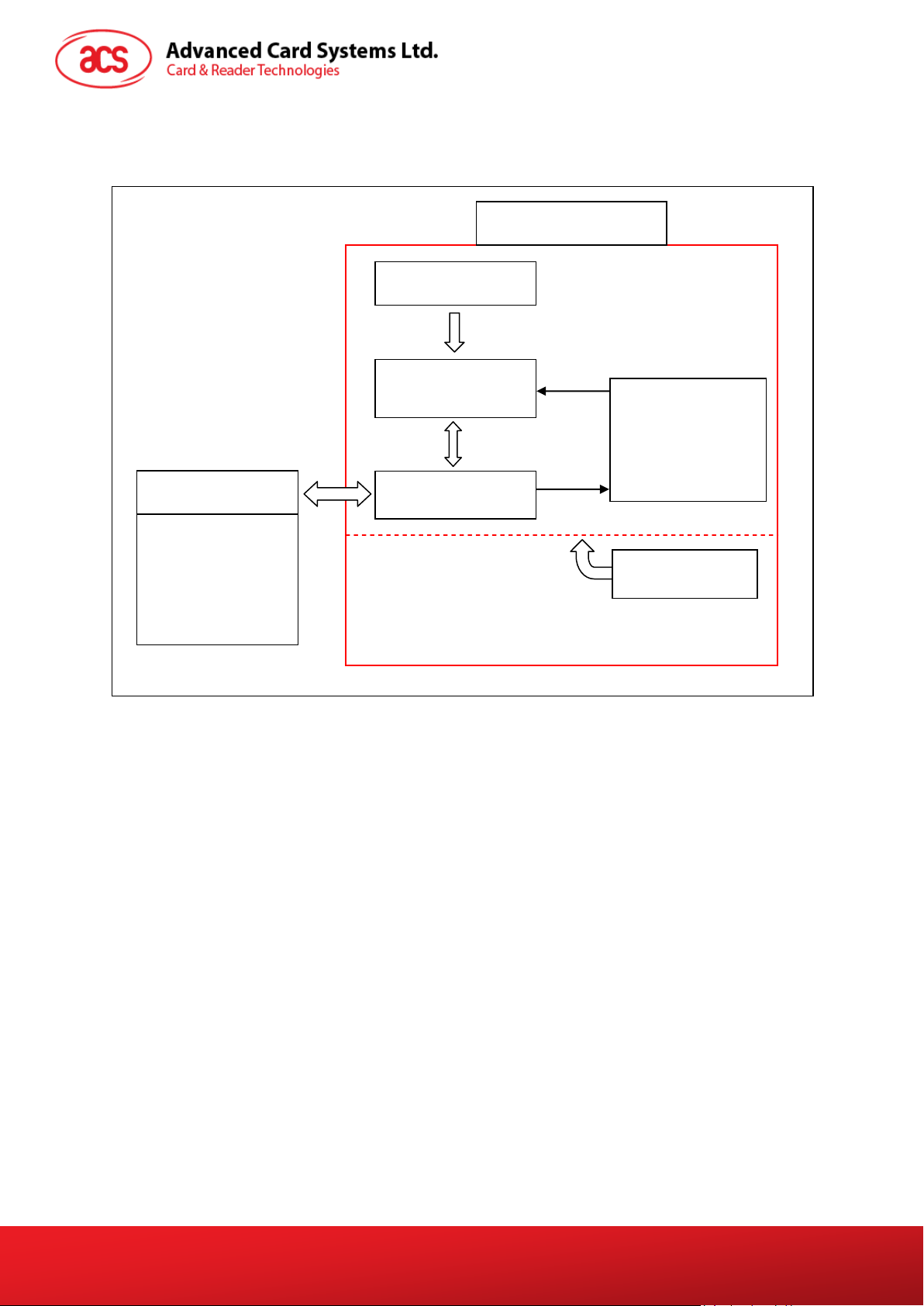
3.0. System Block Design
The system block design of ACR31 is depicted below:
Magnetic Head
Magnetic Stripe
ISO7810/7811
Power
Management
Audio Jack
Mobile Device
MCU
Battery
Figure 1: System Block Diagram
Page 5 of 19
ACR31 – Reference Manual info@acs.com.hk
Version 1.00
www.acs.com.hk
Page 6

4.0. Hardware Design
4.1. Battery
ACR31 is using a CR2016 battery which has a capacity of 90 mAh.
4.2. Audio Channel
4.2.1. Communication Parameters
ACR31 is connected to a mobile device through Audio Channel.
Pin Signal Function
1 Left Transmit the data to ACR31
2 Right Reset signal to ACR31
3 GND GND
4 MIC Transmit the data to smart phone
Table 1: 3.5mm Audio Socket Wiring
4.3. Magnetic Stripe Card Interface
ACR31 can read any magnetic stripe card that conforms to ISO 7810/7811 standards. ISO 7810
specifies the physical characteristics of the card, while ISO 7811 specifies the recording technique
used in identification cards.
High-coercivity (HiCo) magnetic stripes are typically black in color and are encoded with a stronger
magnetic field (2750 Oersted). This makes HiCo cards more durable because the data encoded on
the stripes are less likely to be unintentionally erased when exposed to an outside magnetic field.
When swiped across the magnetic head, HiCo magnetic stripes can induce larger signal pulses and
are more easily being detected and decoded.
Low-coercivity (LoCo) magnetic stripes are generally brown in color and are encoded with lower
magnetic field intensity (300 Oersted). They will induce small signal pulses compared to HiCo cards
when swiped across the magnetic head. As a result, the S/N (signal-to-noise) ratio is relatively low
and they are more vulnerable to noise interference. A more sophisticated hardware support and signal
processing algorithm are needed to decode the signal correctly.
Since the magnetic fields of HiCo and LoCo cards are different, a magnetic stripe decoder IC with
automatic gain control can be used in the design to cater these two types of cards.
Page 6 of 19
ACR31 – Reference Manual info@acs.com.hk
Version 1.00
www.acs.com.hk
Page 7

5.0. Communication Protocol
ACR31 is a slave device and almost all operations are initiated by the mobile device. The mobile
device that sends the command is carried out in the form of successive command request-response
exchange. Additionally, the new request message should wait until previous response message has
been received (except interrupted by the RDR_to_SPH_TrackData interrupt message).
ACR31 will communicate with a mobile device through its audio jack interface. The communication
channel is bi-directional, with the reader sending data to the mobile device through the MIC pin of the
audio jack while the mobile device sending commands to the reader through the Left-Channel of the
audio jack.
While it’s not operating, the ACR31 will remain in deep sleep mode. Upon receiving a wake up signal
from the mobile device through the Right-Channel of the audio jack, the ACR31 will wake up. ACR31
will then wait for the swipe of the magnetic stripe card or any command message sent by the mobile
device within a timeout limit. After successfully obtaining the data from the swiped card, the ACR31
will perform AES-128 encryption on the received card data and send back the encrypted data to the
mobile device in communication. If the reader fails to obtain a card swipe or command message
within the timeout limit, the ACR31 will go back to deep sleep mode to save battery power.
Before the communication protocol between the ACR31 and the mobile device employ a direct signal
feeding, the signal received from the ACR31 will be passing through a DC offset cancellation filter.
The data to be transmitted will be encoded using the Manchester coding scheme (conforms to IEEE
802.3), with the clock frequency used in the Manchester coding scheme being set at 2.756 kHz. Since
the data transmission speed in the Manchester coding scheme always matches the clock speed, a
maximum baud rate of around 2.756 kbps could be achieved.
The signal interpretation on the mobile device and ACR31 is based on sampling the corresponding
input waveforms. The sampling frequency should be at least double the clock frequency (Nyquist
rate) used in the Manchester coding scheme. After sampling the signals, the data encoded in the
signals could be received by determining the logical zero-crossing time.
5.1. Audio Channel Message
All messages between ACR31 and the mobile device consist of a header containing a frame start byte
(1 byte), a length field (2 bytes) and a message type indicator (1 byte). There is 2-byte CRC at the
end of each message for error detection. The card data will be encrypted using AES-128 encryption
algorithm.
Below list all the messages that would appear between the communications of ACR31 and the mobile
device:
Send-Out Message Code Send-In Message Code
SPH_to_RDR_Reset N/A RDR_to_SPH_GetStatus 80h
SPH_to_RDR_Sleep 63h RDR_to_SPH_FirmwareVersion 81h
SPH_to_RDR_FirmwareVersion 6Fh RDR_to_SPH_ACK 82h
SPH_to_RDR_GetStatus 6Eh
SPH_to_RDR_SetSleepTimeout 6Ch
RDR_to SPH_TrackData 50h
Interrupt-In Message Code
Page 7 of 19
ACR31 – Reference Manual info@acs.com.hk
Version 1.00
www.acs.com.hk
Page 8

6.0. Commands
6.1. SPH_to_RDR_Reset
This reset command will not send any message to ACR31. Instead, the mobile device will generate
several pulses in the right channel of the audio jack that will trigger the ACR31 to perform a hardware
reset. This is the only way to resume the normal operation of ACR31 after it has entered the sleep
mode.
No response will be generated for this command.
Page 8 of 19
ACR31 – Reference Manual info@acs.com.hk
Version 1.00
www.acs.com.hk
Page 9

6.2. SPH_to_RDR_Sleep
This command is used to force the ACR31 to enter sleep mode immediately upon receiving this
command.
Offset Field Size Value Description Encrypted
0
1
3
4
The response to this message is RDR_to_SPH_ACK.
bStartByte
wLength
bMessageType
wCheckSum
1 23h Message start byte.
2 0003h
1 63h
2
Number of extra bytes starting
from the next field for this
message.
CRC16 checksum for all the
preceding fields.
No
Page 9 of 19
ACR31 – Reference Manual info@acs.com.hk
Version 1.00
www.acs.com.hk
Page 10

6.3. SPH_to_RDR_FirmwareVersion
This command is used to retrieve the firmware version string from ACR31.
Offset Field Size Value Description Encrypted
0
1
3
4
When there is no error, the response to this message is RDR_to_SPH_FirmwareVersion.
Otherwise, the response is RDR_to_SPH_ACK which will specify the corresponding error.
bStartByte
wLength
bMessageType
wCheckSum
1 23h Message start byte.
Number of extra bytes starting
2 0003h
1 6Fh
2
from the next field for this
message.
CRC16 checksum for all the
preceding fields.
No
Page 10 of 19
ACR31 – Reference Manual info@acs.com.hk
Version 1.00
www.acs.com.hk
Page 11

6.4. SPH_to_RDR_GetStatus
This command is used to request ACR31 to give a feedback of the current device status to the mobile
device.
Offset Field Size Value Description Encrypted
0
1
3
4
When there is no error, the response to this message is RDR_to_SPH_GetStatus.
Otherwise, the response is RDR_to_SPH_ACK which will specify the corresponding error.
bStartByte
wLength
bMessageType
wCheckSum
1 23h Message start byte.
Number of extra bytes starting
2 0003h
1 6Eh
2
from the next field for this
message.
CRC16 checksum for all the
preceding fields.
No
Page 11 of 19
ACR31 – Reference Manual info@acs.com.hk
Version 1.00
www.acs.com.hk
Page 12

6.5. SPH_to_RDR_SetSleepTimeout
This command is used to request ACR31 to change the sleep timeout value to the one specified.
Offset Field Size Value Description Encrypted
0
1
3
4
4
The response to this message is RDR_to_SPH_ACK.
bStartByte
wLength
bMessageType
bTimeout
wCheckSum
1 23h Message start byte.
2 0004h
1 6Ch
1
2
Number of extra bytes starting
from the next field for this
message.
Sleep timeout value in seconds.
This value should be in the
range of 4 – 20. Other values
are not allowed.
CRC16 checksum for all the
preceding fields.
No
Page 12 of 19
ACR31 – Reference Manual info@acs.com.hk
Version 1.00
www.acs.com.hk
Page 13

6.6. RDR_to_SPH_GetStatus
This message is sent by ACR31 in response to the command message SPH_to_RDR_GetStatus.
Offset Field Size Value Description Encrypted
0
1
3
4
5
bStartByte
wLength
bMessageType
bBatteryLevel
bSleepTimeout
1 23h Message start byte.
Number of extra bytes starting
2 0006h
1 80h
1
1
from the next field for this
message.
00h – Battery Level ≥ 3.0V
01h – 2.9 ≤ Battery Level < 3.0 V
02h – 2.8 ≤ Battery Level < 2.9 V
03h – 2.7 ≤ Battery Level < 2.8 V
04h – 2.6 ≤ Battery Level < 2.7 V
05h – 2.5 ≤ Battery Level < 2.6 V
06h – 2.4 ≤ Battery Level < 2.5 V
07h – 2.3 ≤ Battery Level < 2.4 V
08h – Battery Level < 2.3 V
Active sleep timeout value used
in the reader.
No
6
7
bRFU
wCheckSum
1 00h Reserve for future use.
2
CRC16 checksum for all the
preceding fields.
Page 13 of 19
ACR31 – Reference Manual info@acs.com.hk
Version 1.00
www.acs.com.hk
Page 14

6.7. RDR_to_SPH_FirmwareVersion
This message is sent by ACR31 in response to the command message
SPH_to_RDR_FirmwareVersion.
Offset Field Size Value Description Encrypted
0
1
3
4
16
bStartByte
wLength
bMessageType
abFirmwareVersion
wCheckSum
1 23h Message start byte.
Number of extra bytes starting
2 000Fh
1 81h
12 Firmware version string.
2
from the next field for this
message.
CRC16 checksum for all the
preceding fields.
No
Page 14 of 19
ACR31 – Reference Manual info@acs.com.hk
Version 1.00
www.acs.com.hk
Page 15

6.8. RDR_to_SPH_TrackData
This message is sent by ACR31 when it detects the swiping of card and transfers Track 1 and Track 2
data to the mobile device.
There is no need for the mobile device to send any command message to ACR31 to retrieve the card
data. This message is sent automatically from ACR31 to the mobile device once a card swipe action
is performed and thus is known as an interrupt message.
Offset Field Size Value Description Encrypted
0
1
3
4
83
123
124
125
bStartByte
wLength
bMessageType
abTrack1Data
abTrack2Data
bFieldSeparator
bTrack1DataLength
bTrack2DataLength
1 23h Message start byte.
Number of extra bytes starting
2
1 50h
79
40
1 0Dh
1
1
from the next field for this
message.
Magnetic stripe card track 1
data.
Magnetic stripe card track 2
data.
Effective data length or error
code.
If the MSB is set, It is an error
code. Otherwise, it is data
length.
Effective data length or error
code.
If the MSB is set, It is an error
code. Otherwise, it is data
length.
No
Yes
126
130
132
133
134
bLowVoltageDetector
abRFU
wChecksum
bFieldSeparator
bTrack1Error
4 Reserved for future use.
2
1 0Dh
1
1
CRC16 checksum for data
starting from offset 4 to 129.
Detect the power of Battery
00h – Not enough power
01h – Enough power
Track 1 error register.
If the MSB is set, It is an error
code. Otherwise, it is data
length.
No
Page 15 of 19
ACR31 – Reference Manual info@acs.com.hk
Version 1.00
www.acs.com.hk
Page 16

Offset Field Size Value Description Encrypted
Track 2 error register.
135
bTrack2Error
1
If the MSB is set, It is an error
code. Otherwise, it is error-free.
136
wCheckSum
2
CRC16 checksum for all the
preceding fields.
Page 16 of 19
ACR31 – Reference Manual info@acs.com.hk
Version 1.00
www.acs.com.hk
Page 17

6.9. RDR_to_SPH_ACK
This acknowledgement message is sent by ACR31 to the mobile device specifying the acceptance of
certain command messages. This message also includes the error code whenever appropriate.
Offset Field Size Value Description Encrypted
0
1
3
4
5
bStartByte
wLength
bMessageType
bErrorCode
wCheckSum
1 23h Message start byte.
Number of extra bytes starting
2 0004h
1 82h
1
2
from the next field for this
message.
Specify the error code for the
previously processed command
message.
The possible error codes are
listed in Appendix B.
CRC16 checksum for all the
preceding fields.
No
Page 17 of 19
ACR31 – Reference Manual info@acs.com.hk
Version 1.00
www.acs.com.hk
Page 18

Appendix A. Track Data Error Code
Bit 7
Bit 6 Bit 5 Bit 4 Bit 3 Bit 2 Bit 1
MSB
MSB 0 0 0 0 LRC error End Sentinel error Start Sentinel error
Bits 7 to 1 are error codes.
Error-free = 0
Bit 0
LSB
Page 18 of 19
ACR31 – Reference Manual info@acs.com.hk
Version 1.00
www.acs.com.hk
Page 19

Appendix B. System Error Codes
The following table lists all the system error codes and their corresponding description for ACR31.
Error Code Status
00h ERROR_SUCCESS
FFh ERROR_INVALID_CMD
FEh ERROR_INVALID_PARAM
FDh ERROR_INVALID_CHECKSUM
FCh RROR_INVALID_STARTBYTE
FBh ERROR_UNKNOWN
Page 19 of 19
ACR31 – Reference Manual info@acs.com.hk
Version 1.00
www.acs.com.hk
 Loading...