

Page 1

ACR1283L
Contactless Reader
Standalone
Reference Manual V1.00
Subject to change without prior notice info@acs.com.hk
www.acs.com.hk
Page 2

Table of Contents
1.0. Introduction ............................................................................................................... 4
2.0. Features ..................................................................................................................... 5
3.0. Architecture ............................................................................................................... 7
4.0. Hardware Design ....................................................................................................... 8
4.1. USB ........................................................................................................................................ 8
4.1.1. Communication Parameters ......................................................................................... 8
4.1.2. Endpoints ...................................................................................................................... 8
4.2. Contact Smart Card Interface ................................................................................................ 8
4.2.1. Smart Card Power Supply VCC (C1) ............................................................................ 8
4.2.2. Card Type Selection...................................................................................................... 8
4.2.3. Interface for Microcontroller-based Cards .................................................................... 8
4.3. Contactless Smart Card Interface ......................................................................................... 9
4.3.1. Carrier Frequency ......................................................................................................... 9
4.3.2. Card Polling ................................................................................................................... 9
5.0. Software Design ...................................................................................................... 10
5.1. CCID Protocol ...................................................................................................................... 10
5.2. CCID Commands ................................................................................................................. 11
5.2.1. CCID Command Pipe Bulk-OUT Messages ............................................................... 11
5.2.2. CCID Bulk-IN Messages ............................................................................................. 15
5.3. Contactless Smart Card Protocol ........................................................................................ 17
5.3.1. ATR Generation .......................................................................................................... 17
5.3.2. Pseudo APDUs for Contactless Interface ................................................................... 19
5.4. Peripherals Control .............................................................................................................. 31
5.4.1. Get Firmware Version ................................................................................................. 31
5.4.2. Set Default LED and Buzzer Behaviors ...................................................................... 32
5.4.3. Read Default LED and Buzzer Behaviors ................................................................... 33
5.4.4. Set Automatic PICC Polling ........................................................................................ 34
5.4.5. Read Automatic PICC Polling ..................................................................................... 36
5.4.6. Set the PICC Operating Parameter ............................................................................ 37
5.4.7. Read the PICC Operating Parameter ......................................................................... 38
5.4.8. Set Auto PPS .............................................................................................................. 39
5.4.9. Read Auto PPS ........................................................................................................... 40
5.4.10. Set Antenna Field ........................................................................................................ 41
5.4.11. Read Antenna Field Status ......................................................................................... 42
5.4.12. Two LEDs Control ....................................................................................................... 43
5.4.13. LED Status .................................................................................................................. 44
5.4.14. Four LEDs Control ...................................................................................................... 45
5.4.15. Buzzer Control ............................................................................................................ 46
5.4.16. LCD Control Command ............................................................................................... 47
List of Figures
Figure 1 : ACR1283L Architecture ......................................................................................................... 7
Figure 2 : LCD Display Font Table ....................................................................................................... 49
Page 2 of 55
ACR1283L – Reference Manual info@acs.com.hk
Version 1.00
www.acs.com.hk
Page 3

List of Tables
Table 1 : USB Interface Wiring ............................................................................................................... 8
Table 2 : Mifare 1K Memory Map ......................................................................................................... 23
Table 3 : Mifare 4K Memory Map ......................................................................................................... 23
Table 4 : Mifare Ultralight Memory Map ............................................................................................... 24
Table 5 : Scrolling Period ...................................................................................................................... 53
Table 6 : Scrolling Direction .................................................................................................................. 53
Page 3 of 55
ACR1283L – Reference Manual info@acs.com.hk
Version 1.00
www.acs.com.hk
Page 4

1.0. Introduction
The ACR1283L Standalone Contactless Reader is a device that is used for accessing contactless
cards. Its contactless interface is used to access ISO 14443 Types A and B cards and Mifare series.
ACR1283L also has Secure Access Module (SAM) interface that ensures a high level of security in
contactless smart card applications.
ACR1283L can operate in both PC-linked and Standalone mode. In PC-linked application, the
ACR1283L serves as an intermediary device between the PC and the smart card. The reader is
connected to the PC via its USB port and carries out the PC’s commands – whether the command is
used in order to communicate with a contactless or SAM card, or control the device peripherals (e.g.
LCD, keypad, LEDs, and buzzer). This document provides a detailed guide in implementing PC/SC
APDU commands for device peripherals and contactless cards following the PC/SC specifications.
Page 4 of 55
ACR1283L – Reference Manual info@acs.com.hk
Version 1.00
www.acs.com.hk
Page 5

2.0. Features
• Dual Operation Modes:
o PC-linked
o Standalone
• PC-linked Operation:
o USB 2.0 Full Speed Interface
o CCID Compliance
o Supports PC/SC
o Supports CT-API (through wrapper on top of PC/SC)
• Standalone Operation:
o Support for third-party application programming
o Over 400 KB memory space for third-party application
o Over 500 KB memory space for data storage
o Supported development platform:
IAR Embedded Workbench, Version 5.50 or above
CoIDE(GCC), Version 1.3.0 or above
• Smart Card Reader:
o Read/Write speed of up to 848 kbps
o Built-in antenna for contactless tag access, with card reading distance of up to 50 mm
(depending on tag type)
o Support for ISO 14443 Part 4 Type A and B and Mifare series
o Built-in anti-collision feature (only one tag is accessed at any time)
o Four ISO 7816 compliant SAM slots
• Built-in Peripherals:
o Two-line graphic LCD
o Four user-controllable LEDs
o User-controllable buzzer
o Twelve-key capacitive touch keypad
• Real-time clock (RTC) with independent back up battery
• In-device AES (128 and 256), DES and 3DES encryption
• Supports Android
• USB Firmware Upgradability
TM
OS 3.1 and above
Page 5 of 55
ACR1283L – Reference Manual info@acs.com.hk
Version 1.00
www.acs.com.hk
Page 6

• Compliant with the following standards:
o ISO 14443
o CE
o FCC
o PC/SC
o CCID
o Microsoft® WHQL
o RoHS
Page 6 of 55
ACR1283L – Reference Manual info@acs.com.hk
Version 1.00
www.acs.com.hk
Page 7
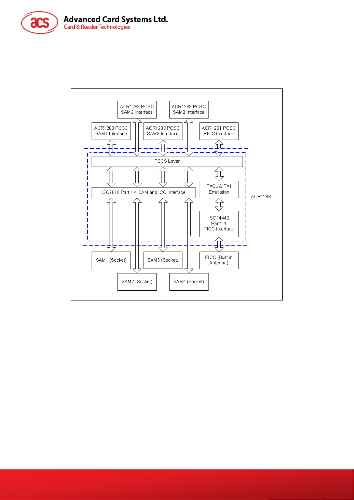
3.0. Architecture
The protocol between ACR1283L and the PC is using CCID protocol. All the communication between
PICC and SAM are PCSC-compliant.
Figure 1: ACR1283L Architecture
Page 7 of 55
ACR1283L – Reference Manual info@acs.com.hk
Version 1.00
www.acs.com.hk
Page 8
4.0. Hardware Design
4.1. USB
The ACR1283L is connected to a computer through a USB following the USB standard.
4.1.1. Communication Parameters
The ACR1283L is connected to a computer through USB as specified in the USB Specification 2.0.
The ACR1283L is working in full speed mode, i.e. 12 Mbps.
Pin Signal Function
1 V
2 D-
3 D+
4 GND
Note: In order for ACR1283L to function properly through USB interface, the driver should be
installed.
BUS
+5 V power supply for the reader.
Differential signal transmits data between ACR1283L and PC.
Differential signal transmits data between ACR1283L and PC.
Reference voltage level for power supply.
Table 1: USB Interface Wiring
4.1.2. Endpoints
The ACR1283L uses the following endpoints to communicate with the host computer:
Control Endpoint For setup and control purpose
Bulk OUT For command to sent from host to ACR1283L (data packet size is 64 bytes)
Bulk IN For response to sent from ACR1283L to host (data packet size is 64 bytes)
Interrupt IN For card status message to sent from ACR1283L to host (data packet size is 8
bytes)
4.2. Contact Smart Card Interface
The interface between the ACR1283L and the inserted smart card follows the specifications of ISO
7816-3 with certain restrictions or enhancements to increase the practical functionality of the
ACR1283L.
4.2.1. Smart Card Power Supply VCC (C1)
The current consumption of the inserted card must not be higher than 50 mA.
4.2.2. Card Type Selection
Before activating the inserted card, the controlling PC always needs to select the card type through
the proper command sent to the ACR1283L. This includes both memory card and MCU-based cards.
For MCU-based cards the reader allows to select the preferred protocol, T=0 or T=1. However, this
selection is only accepted and carried out by the reader through the PPS when the card inserted in
the reader supports both protocol types. Whenever a MCU-based card supports only one protocol
type, T=0 or
selected by the application.
T=1, the reader automatically uses that protocol type, regardless of the protocol type
4.2.3. Interface for Microcontroller-based Cards
For microcontroller-based smart cards only the contacts C1 (VCC), C2 (RST), C3 (CLK), C5 (GND)
Page 8 of 55
ACR1283L – Reference Manual info@acs.com.hk
Version 1.00
www.acs.com.hk
Page 9

and C7 (I/O) are used. A frequency of 4.8 MHz is applied to the CLK signal (C3).
4.3. Contactless Smart Card Interface
The interface between the ACR1283L and the contactless interface follows the specifications of ISO
14443 with certain restrictions or enhancements to increase the practical functionality of the
ACR1283L.
4.3.1. Carrier Frequency
The carrier frequency for ACR1283L is 13.56 MHz.
4.3.2. Card Polling
The ACR1283L automatically polls the contactless cards that are within the field. ISO 14443-4 Type A,
ISO 14443-4 Type B and Mifare cards are supported.
Page 9 of 55
ACR1283L – Reference Manual info@acs.com.hk
Version 1.00
www.acs.com.hk
Page 10

5.0. Software Design
5.1. CCID Protocol
ACR1283L shall interface with the host with USB connection. A specification, namely CCID, has been
released within the industry defining such a protocol for the USB chip-card interface devices. CCID
covers all the protocols required for operating smart cards and PIN.
The configurations and usage of USB endpoints on ACR1283L shall follow CCID section 3. An
overview is summarized below:
• Control Commands are sent on control pipe (default pipe). These include class-specific
requests and USB standard requests. Commands that are sent on the default pipe report
information back to the host on the default pipe.
• CCID Events are sent on the interrupt pipe.
• CCID Commands are sent on BULK-OUT endpoint. Each command sent to ACR1283L has
an associated ending response. Some commands can also have intermediate responses.
• CCID Responses are sent on BULK-IN endpoint. All commands sent to ACR1283L have to
be sent synchronously. (i.e. bMaxCCIDBusySlots is equal to 1 for ACR1283L).
The supported CCID features by ACR1283L are indicated in its class descriptor:
Offset Field Size Value Description
0
1
2
4
5
6
10
14
18
bLength
bDescriptorType
bcdCCID
bMaxSlotIndex
bVoltageSupport
dwProtocols
dwDefaultClock
dwMaximumClock
bNumClockSupported
1 36h Size of this descriptor, in bytes.
1 21h CCID Functional Descriptor type.
CCID Specification Release
2 0110h
1 04h
1 07h
4 00000003h
4 00000FA0h
4 00000FA0h
1 00h
Number in Binary-Coded
decimal.
Five slots are available on
ACR1283L.
ACR1283L can supply 1.8 V, 3.0
V and 5.0 V to its slot.
ACR1283L supports T=0 and
T=1 Protocol.
Default ICC clock frequency is 4
MHz.
Maximum supported ICC clock
frequency is 4 MHz.
Does not support manual setting
of clock frequency.
19
23
27
28
dwDataRate
dwMaxDataRate
bNumDataRatesSupported
dwMaxIFSD
4 00002A00h
4 0001F808h
1 00h
4 00000200h
Default ICC I/O data rate is
10752 bps.
Maximum supported ICC I/O
data rate is 344100 bps.
Does not support manual setting
of data rates.
Maximum IFSD supported by
ACR1283L for protocol T=1 is
512.
Page 10 of 55
ACR1283L – Reference Manual info@acs.com.hk
Version 1.00
www.acs.com.hk
Page 11
Offset Field Size Value Description
32
36
40
44
48
49
50
52
dwSynchProtocols
dwMechanical
dwFeatures
dwMaxCCIDMessageLength
bClassGetResponse
bClassEnvelope
wLCDLayout
bPINSupport
4 00000000h
4 00000000h
4 00040040h
4 0000020Ah
1 00h
1 00h
2 0000h No LCD.
1 00h No PIN Verification.
ACR1283L does not support
synchronous card.
ACR1283L does not support
special mechanical
characteristics.
ACR1283L supports the
following features:
• Automatic parameters
negotiation made by the
CCID
• Short and Extended APDU
level exchange with CCID
Maximum message length
accepted by ACR1283L is 522
bytes.
Indicates that the CCID echoes
the class of the APDU.
Indicates that the CCID echoes
the class of the APDU.
53
bMaxCCIDBusySlots
1 01h
Only one slot can be
simultaneously busy.
5.2. CCID Commands
5.2.1. CCID Command Pipe Bulk-OUT Messages
ACR1283L shall follow the CCID Bulk-OUT Messages as specified in CCID section 4. In addition, this
specification defines some extended commands for operating additional features. This section lists
the CCID Bulk-OUT Messages to be supported by ACR1283L.
5.2.1.1. PC_to_RDR_IccPowerOn
This command is used to activate the card slot and return ATR from the card.
Offset Field Size Value Description
0
1
2
5
6
bMessageType
dwLength
bSlot
bSeq
bPowerSelect
1 62h
4 00000000h Size of extra bytes of this message.
1 Identifies the slot number for this command.
1 Sequence number for command.
Voltage that is applied to the ICC.
1
00h = Automatic Voltage Selection
01h = 5 V
02h = 3 V
7
abRFU
2 Reserved for future use.
Page 11 of 55
ACR1283L – Reference Manual info@acs.com.hk
Version 1.00
www.acs.com.hk
Page 12
The response to this message is the RDR_to_PC_DataBlock message and the data returned is the
Answer To Reset (ATR) data.
5.2.1.2. PC_to_RDR_IccPowerOff
This command is used to deactivate the card slot.
Offset Field Size Value Description
0
1
5
6
7
The response to this message is the RDR_to_PC_SlotStatus message.
bMessageType
dwLength
bSlot
bSeq
abRFU
1 63h
4 00000000h Size of extra bytes of this message.
1 Identifies the slot number for this command.
1 Sequence number for command.
3 Reserved for future use.
5.2.1.3. PC_to_RDR_GetSlotStatus
This command is used to get the current status of the slot.
Offset Field Size Value Description
0
1
5
6
7
bMessageType
dwLength
bSlot
bSeq
abRFU
1 65h
4 00000000h Size of extra bytes of this message.
1 Identifies the slot number for this command.
1 Sequence number for command.
3 Reserved for future use.
The response to this message is the RDR_to_PC_SlotStatus message.
5.2.1.4. PC_to_RDR_XfrBlock
This command is used to transfer data block to the ICC.
Offset Field Size Value Description
0
1
5
6
7
8
10
bMessageType
dwLength
bSlot
bSeq
bBWI
wLevelParameter
abData
1 6Fh
4 Size of abData field of this message
1 Identifies the slot number for this command
1 Sequence number for command
Used to extend the CCIDs Block Waiting Timeout
1
2 0000h RFU (TPDU exchange level)
Byte
array
for this current transfer. The CCID will timeout the
block after “this number multiplied by the Block
Waiting Time” has expired.
Data block sent to the CCID. Data is sent “as is” to
the ICC (TPDU exchange level)
Page 12 of 55
ACR1283L – Reference Manual info@acs.com.hk
Version 1.00
www.acs.com.hk
Page 13
The response to this message is the RDR_to_PC_DataBlock message.
5.2.1.5. PC_to_RDR_Escape
This command is used to access extended features.
Offset Field Size Value Description
0
1
5
6
7
10
The response to this command message is the RDR_to_PC_Escape response message.
bMessageType
dwLength
bSlot
bSeq
abRFU
abData
1 6Bh
4 Size of abData field of this message.
1 Identifies the slot number for this command.
1 Sequence number for command.
3 Reserved for Future Use.
Byte array Data block sent to the CCID.
5.2.1.6. PC_to_RDR_GetParameters
This command is used to get slot parameters.
Offset Field Size Value Description
0
1
5
6
7
bMessageType
dwLength
bSlot
bSeq
abRFU
1 6Ch
4 00000000h Size of extra bytes of this message.
1 Identifies the slot number for this command.
1 Sequence number for command.
3 Reserved for future use.
The response to this message is the RDR_to_PC_Parameters message.
5.2.1.7. PC_to_RDR_ResetParameters
This command is used to reset slot parameters to default value.
Offset Field Size Value Description
0
1
5
6
7
The response to this message is the RDR_to_PC_Parameters message.
bMessageType
DwLength
BSlot
BSeq
AbRFU
1 6Dh
4 00000000h Size of extra bytes of this message.
1 Identifies the slot number for this command.
1 Sequence number for command.
3 Reserved for future use.
5.2.1.8. PC_to_RDR_SetParameters
This command is used to set the slot parameters.
Offset Field Size Value Description
0
bMessageType
1 61h
Page 13 of 55
ACR1283L – Reference Manual info@acs.com.hk
Version 1.00
www.acs.com.hk
Page 14
Offset Field Size Value Description
1
5
6
7
8
10
Protocol Data Structure for Protocol T=0 (dwLength=00000005h)
Offset Field Size Value Description
abProtocolDataStructure
dwLength
bSlot
bSeq
bProtocolNum
abRFU
4 Size of extra bytes of this message.
1
1 Sequence number for command.
1
2 Reserved for future use.
Byte
array
Identifies the slot number for this
command.
Specifies what protocol data structure
follows.
00h = Structure for protocol T=0
01h = Structure for protocol T=1
The following values are reserved for
future use:
80h = Structure for 2-wire protocol
81h = Structure for 3-wire protocol
82h = Structure for I2C protocol
Protocol Data Structure.
B7-4 – FI – Index into the table 7 in ISO/IEC
7816-3:1997 selecting a clock rate conversion
10
11
12
13
14
bmFindexDindex
bmTCCKST0
bGuardTimeT0
bWaitingIntegerT0
bClockStop
1
1
1
1 WI for T=0 used to define WWT
1
factor
B3-0 – DI - Index into the table 8 in
ISO/IEC 7816-3:1997 selecting a baud rate
conversion factor
B0 – 0b, B7-2 – 000000b
B1 – Convention used (b1=0 for direct, b1=1 for
inverse) Note: The CCID ignores this bit.
Extra Guardtime between two characters. Add 0
to 254 etu to the normal guardtime of 12etu. FFh
is the same as 00h.
ICC Clock Stop Support.
00h = Stopping the Clock is not allowed
01h = Stop with Clock signal Low
02h = Stop with Clock signal High
03h = Stop with Clock either High or Low
Page 14 of 55
ACR1283L – Reference Manual info@acs.com.hk
Version 1.00
www.acs.com.hk
Page 15

Protocol Data Structure for Protocol T=1 (dwLength=00000007h)
Offset Field Size Value Description
B7-4 – FI – Index into the table 7 in ISO/IEC
7816-3:1997 selecting a clock rate conversion
10
11
12
bmFindexDindex
BmTCCKST1
BGuardTimeT1
1
1
1
factor
B3-0 – DI - Index into the table 8 in
ISO/IEC 7816-3:1997 selecting a baud rate
conversion factor
B7-2 – 000100b
B0 – Checksum type (b0=0 for LRC, b0=1 for
CRC
B1 – Convention used (b1=0 for direct, b1=1 for
inverse) Note: The CCID ignores this bit.
Extra Guardtime (0 to 254 etu between two
characters). If value is FFh, then guardtime is
reduced by 1 etu.
13
14
15
16
The response to this message is the RDR_to_PC_Parameters message.
BwaitingIntegerT1
bClockStop
bIFSC
bNadValue
1
1
1 Size of negotiated IFSC
1 00h Only support NAD = 00h
B7-4 = BWI values 0-9 valid
B3-0 = CWI values 0-Fh valid
ICC Clock Stop Support.
00h = Stopping the Clock is not allowed
01h = Stop with Clock signal Low
02h = Stop with Clock signal High
03h = Stop with Clock either High or Low
5.2.2. CCID Bulk-IN Messages
The Bulk-IN messages are used in response to the Bulk-OUT messages. ACR1283L shall follow the
CCID Bulk-IN Messages as specified in CCID section 4. This section lists the CCID Bulk-IN Messages
to be supported by ACR1283L.
5.2.2.1. RDR_to_PC_DataBlock
This message is sent by ACR1283L in response to PC_to_RDR_IccPowerOn, PC_to_RDR_XfrBlock
and PC_to_RDR_Secure messages.
Offset Field Size Value Description
0
1
5
6
7
bMessageType
dwLength
bSlot
bSeq
bStatus
1 80h
4 Size of extra bytes of this message.
1 Same value as in Bulk-OUT message.
1 Same value as in Bulk-OUT message.
1
Indicates that a data block is being sent from
the CCID.
Slot status register as defined in CCID section
4.2.1.
Page 15 of 55
ACR1283L – Reference Manual info@acs.com.hk
Version 1.00
www.acs.com.hk
Page 16
Offset Field Size Value Description
8
9
10
bError
bChainParameter
abData
1
1 00h RFU (TPDU exchange level).
Byte array
Slot error register as defined in CCID section
4.2.1 and this specification section 5.2.8.
This field contains the data returned
by the CCID.
5.2.2.2. RDR_to_PC_Escape
This message is sent by ACR1283L in response to PC_to_RDR_Escape messages.
Offset Field Size Value Description
0
1
5
6
7
8
bMessageType
dwLength
bSlot
bSeq
bStatus
bError
1 83h
4 Size of abData field of this message.
1 Same value as in Bulk-OUT message.
1 Same value as in Bulk-OUT message.
1
1
Slot status register as defined in CCID
section 4.2.1.
Slot error register as defined in CCID
section 4.2.1 and this specification section
5.2.8.
9
10
bRFU
abData
1 00h RFU.
Byte array
This field contains the data returned
by the CCID.
5.2.2.3. RDR_to_PC_SlotStatus
This message is sent by ACR1283L in response to PC_to_RDR_IccPowerOff,
PC_to_RDR_GetSlotStatus, PC_to_RDR_Abort messages and class specific ABORT request.
Offset Field Size Value Description
0
1
5
6
7
8
9
bMessageType
dwLength
bSlot
bSeq
bStatus
bError
bClockStatus
1 81h
4 00000000h Size of extra bytes of this message.
1 Same value as in Bulk-OUT message.
1 Same value as in Bulk-OUT message.
1
1
1
Slot status register as defined in CCID section
4.2.1.
Slot error register as defined in CCID section
4.2.1 and this specification section 5.2.8.
Value:
00h = Clock running
01h = Clock stopped in state L
02h = Clock stopped in state H
03h = Clock stopped in an unknown state
All other values are RFU.
Page 16 of 55
ACR1283L – Reference Manual info@acs.com.hk
Version 1.00
www.acs.com.hk
Page 17
5.2.2.4. RDR_to_PC_Parameters
This message is sent by ACR1283L in response to PC_to_RDR_GetParameters,
PC_to_RDR_ResetParameters and PC_to_RDR_SetParameters messages.
Offset Field Size Value Description
0
1
5
6
7
8
9
10
bMessageType
dwLength
bSlot
bSeq
bStatus
bError
bProtocolNum
abProtocolDataStructure
1 82h
4 Size of extra bytes of this message.
1 Same value as in Bulk-OUT message.
1 Same value as in Bulk-OUT message.
1
1
1
Byte
array
Slot status register as defined in CCID
section 4.2.1.
Slot error register as defined in CCID
section 4.2.1 and this specification section
5.2.8.
Specifies what protocol data structure
follows.
00h = Structure for protocol T=0
01h = Structure for protocol T=1
The following values are reserved for
future use:
80h = Structure for 2-wire protocol
81h = Structure for 3-wire protocol
82h = Structure for I2C protocol
Protocol Data Structure as summarized in
section 5.2.3.
5.3. Contactless Smart Card Protocol
5.3.1. ATR Generation
If the reader detects a PICC, an ATR is sent to the PCSC driver for identifying the PICC.
5.3.1.1. ATR Format for ISO 14443 Part 3 PICCs
Byte Value (Hex) Designation Description
0 3B Initial Header
Higher nibble 8 means: no TA1, TB1, TC1 only TD1
1 8N T0
2 80 TD1
3 01 TD2
is following.
Lower nibble N is the number of historical bytes
(HistByte 0 to HistByte N-1)
Higher nibble 8 means: no TA2, TB2, TC2 only TD2
is following.
Lower nibble 0 means T = 0
Higher nibble 0 means no TA3, TB3, TC3, TD3
following.
Lower nibble 1 means T = 1
Page 17 of 55
ACR1283L – Reference Manual info@acs.com.hk
Version 1.00
www.acs.com.hk
Page 18

Byte Value (Hex) Designation Description
Category indicator byte, 80 means A status indicator
80 T1
may be present in an optional COMPACT-TLV data
object.
4F
0C Length.
4 to 3+N
RID
SS Byte for standard.
C0 .. C1 Bytes for card name.
00 00 00 00 RFU RFU # 00 00 00 00
4+N UU TCK Exclusive-oring of all the bytes T0 to Tk
Example:
ATR for Mifare 1K = {3B 8F 80 01 80 4F 0C A0 00 00 03 06 03 00 01 00 00 00 00 6Ah}
Length (YY) = 0x0Ch
RID = {A0 00 00 03 06h} (PC/SC Workgroup)
Standard (SSh) = 03h (ISO 14443A, Part 3)
Card Name (C0 .. C1h) = {00 01h} (Mifare 1K)
Tk
Application identifier Presence Indicator.
Registered Application Provider Identifier (RID) # A0
00 00 03 06
Card Name (C0 .. C1)
00 01: Mifare 1K FF 28: JCOP 30
00 02: Mifare 4K FF [SAK]: Undefined tags
00 03: Mifare Ultralight
00 26: Mifare Mini
5.3.1.2. ATR Format for ISO 14443 Part 4 PICCs
Byte Value (Hex) Designation Description
0 3B Initial Header
Higher nibble 8 means: no TA1, TB1, TC1 only TD1
1 8N T0
2 80 TD1
3 01 TD2
is following.
Lower nibble N is the number of historical bytes
(HistByte 0 to HistByte N-1)
Higher nibble 8 means: no TA2, TB2, TC2 only TD2
is following.
Lower nibble 0 means T = 0
Higher nibble 0 means no TA3, TB3, TC3, TD3
following.
Lower nibble 1 means T = 1
XX T1
4 to 3 + N
XX Tk
Historical Bytes:
Page 18 of 55
ACR1283L – Reference Manual info@acs.com.hk
Version 1.00
www.acs.com.hk
Page 19

XX
ISO 14443-A:
Byte Value (Hex) Designation Description
XX
The historical bytes from ATS response. Refer to the
ISO 14443-4 specification.
ISO 14443-B:
Byte1-4 Byte5-7 Byte8
Application
Data from
ATQB
Protocol Info
Byte from
ATQB
Higher
nibble=MBLI
from ATTRIB
command
Lower nibble
(RFU)=0
4+N UU TCK Exclusive-oring of all the bytes T0 to Tk
Example 1:
ATR for DESFire = { 3B 81 80 01 80 80h } // 6 bytes of ATR
Note: Use the APDU “FF CA 01 00 00h” to distinguish the ISO 14443A-4 and ISO 14443B-4 PICCs,
and retrieve the full ATS if available. ISO 14443A-3 or ISO 14443B-3/4 PICCs do have ATS returned.
APDU Command = FF CA 01 00 00h
APDU Response = 06 75 77 81 02 80 90 00h
ATS = {06 75 77 81 02 80h}
Example 2:
ATR for EZ-Link = {3B 88 80 01 1C 2D 94 11 F7 71 85 00 BEh}
Application Data of ATQB = 1C 2D 94 11h
Protocol Information of ATQB = F7 71 85h
MBLI of ATTRIB = 00h
5.3.2. Pseudo APDUs for Contactless Interface
5.3.2.1. Get Data
This command returns the serial number or ATS of the “connected PICC.”
Get UID APDU Format (5 Bytes)
Command Class INS P1 P2 Le
Get Data FFh CAh
00h
01h
00h
00h
(Max. Length)
If P1 = 0x00h, Get UID Response Format (UID + 2 Bytes)
Response Data Out
Result
UID
(LSB)
… …
UID
(MSB)
SW1 SW2
Page 19 of 55
ACR1283L – Reference Manual info@acs.com.hk
Version 1.00
www.acs.com.hk
Page 20

If P1 = 0x01h, Get ATS of a ISO 14443 A card (ATS + 2 Bytes)
Response Data Out
Result ATS SW1 SW2
Response Codes
Results SW1 SW2 Meaning
Success 90 00h The operation is completed successfully.
Warning 62 82h
Error 6C XXh
Error 63 00h The operation is failed.
Error 6A 81h Function not supported.
Examples:
// To get the serial number of the “connected PICC.”
UINT8 GET_UID[5]={0xFFh, 0xCAh, 0x00h, 0x00h, 0x00h};
// To get the ATS of the “connected ISO 14443-A PICC.”
UINT8 GET_ATS[5]={0xFFh, 0xCAh, 0x01h, 0x00h, 0x00h};
End of UID/ATS reached before Le bytes (Le is greater
than UID Length).
Wrong length (wrong number Le: ‘XXh’ encodes the
exact number) if Le is less than the available UID length.
5.3.2.2. PICC Commands (T=CL Emulation) for Mifare 1K/4K Memory Cards
5.3.2.2.1. Load Authentication Keys
This command loads the authentication keys into the reader. The authentication keys are used to
authenticate the particular sector of the Mifare 1K/4K Memory Card. Two kinds of authentication key
locations are provided, volatile and non-volatile key locations respectively.
Load Authentication Keys APDU Format (11 Bytes)
Command Class INS P1 P2 Lc Data In
Load Authentication
Keys
Where:
Key Structure (1 Byte): 0x00h = Key is loaded into the reader volatile memory
Key Number (1 Byte):
0x00h ~ 0x1Fh = Non-volatile memory for storing keys. The keys are permanently
FFh 82h
0x20h = Key is loaded into the reader non-volatile memory
Other = Reserved
stored in the reader and will not be disappeared even the reader is
disconnected from the PC. It can store up to 32 keys inside the
reader non-volatile memory.
Key
Structure
Key
Number
06h
Key
(6 bytes)
Page 20 of 55
ACR1283L – Reference Manual info@acs.com.hk
Version 1.00
www.acs.com.hk
Page 21

0x20h (Session Key) = Volatile memory for storing a temporally key. The key will be
disappeared once the reader is disconnected from the PC. Only 1
volatile key is provided. The volatile key can be used as a session
key for different sessions.
Note: Default Value = {FF FF FF FF FF FFh}
Key (6 Bytes): The key value loaded into the reader, e.g. {FF FF FF FF FF FFh}
Load Authentication Keys Response Format (2 Bytes)
Response Data Out
Result SW1 SW2
Load Authentication Keys Response Codes
Results SW1 SW2 Meaning
Success 90 00h The operation is completed successfully.
Error 63 00h The operation is failed.
Examples:
// Load a key {FF FF FF FF FF FFh} into the non-volatile memory location 0x05h.
APDU = {FF 82 20 05 06 FF FF FF FF FF FFh}
// Load a key {FF FF FF FF FF FFh} into the volatile memory location 0x20h.
APDU = {FF 82 00 20 06 FF FF FF FF FF FFh}
Notes:
1. Basically, the application should know all the keys being used. It is recommended to store all
the required keys to the non-volatile memory for security reasons. The contents of both
volatile and non-volatile memories are not readable by the outside world.
2. The content of the volatile memory “Session Key 0x20h” remains valid until the reader is reset
or power-off. The session key is useful for storing any key value that is changing from time to
time. The session key is stored in the “Internal RAM”, while the non-volatile keys are stored in
“EEPROM” that is relatively slower than “Internal RAM”.
3. It is not recommended to use the “non-volatile key locations 0x00h ~ 0x1Fh” to store any
“temporally key value” that will be changed so often. The “non-volatile keys” are supposed to
be used for storing any “key value” that will not change frequently. If the “key value” is
supposed to be changed from time to time, please store the “key value” to the “volatile key
location 0x020h.”
5.3.2.2.2. Authentication for Mifare 1K/4K
This command uses the keys stored in the reader to do authentication with the Mifare 1K/4K card
(PICC). Two types of authentication keys are used: TYPE_A and TYPE_B.
Load Authentication Keys APDU Format (6 Bytes) (Obsolete)
Command Class INS P1 P2 P3 Data In
Authentication FFh 88h 00h
Block
Number
Key
Type
Key
Number
Page 21 of 55
ACR1283L – Reference Manual info@acs.com.hk
Version 1.00
www.acs.com.hk
Page 22

Load Authentication Keys APDU Format (10 Bytes)
Command Class INS P1 P2 Lc Data In
Authentication FFh 86h 00h 00h 05h
Authenticate Data Bytes (5 Byte)
Byte1 Byte 2 Byte 3 Byte 4 Byte 5
Version
0x01h
Where:
Block Number (1 Byte): The memory block to be authenticated.
For Mifare 1K card, it has totally 16 sectors and each sector consists of 4 consecutive blocks. For
example, Sector 0x00h consists of Blocks {0x00h, 0x01h, 0x02h and 0x03h}; Sector 0x01h
consists of Blocks {0x04h, 0x05h, 0x06h and 0x07h}; the last sector 0x0Fh consists of Blocks
{0x3Ch, 0x3Dh, 0x3Eh and 0x3Fh}. Once the authentication is done successfully, there is no
need to do the authentication again provided that the blocks to be accessed are belonging to the
same sector. Please refer to the Mifare 1K/4K specification for more details.
Note: Once the block is authenticated successfully, all the blocks belonging to the same sector
are accessible.
0x00h Block Number Key Type Key Number
Authenticate
Data Bytes
Key Type (1 Byte): 0x60h = Key is used as a TYPE A key for authentication
0x61h = Key is used as a TYPE B key for authentication
Key Number (1 Byte):
0x00h ~ 0x1Fh = Non-volatile memory for storing keys. The keys are permanently stored in
the reader and will not be disappeared even the reader is disconnected
from the PC. It can store 32 keys into the reader non-volatile memory.
0x20h (Session Key) = Volatile memory for storing keys. The keys will be disappeared when the
reader is disconnected from the PC. Only 1 volatile key is provided. The
volatile key can be used as a session key for different sessions.
Load Authentication Keys Response Format (2 Bytes)
Response Data Out
Result SW1 SW2
Load Authentication Keys Response Codes
Results SW1 SW2 Meaning
Success 90 00h The operation is completed successfully.
Error 63 00h The operation is failed.
Page 22 of 55
ACR1283L – Reference Manual info@acs.com.hk
Version 1.00
www.acs.com.hk
Page 23

Sectors
(Total 16 sectors. Each
sector consists of 4
consecutive blocks)
Sector 0 0x00h ~ 0x02h 0x03h
Sector 1 0x04h ~ 0x06h 0x07h
..
..
Sector 14 0x38h ~ 0x0Ah 0x3Bh
Sector 15 0x3Ch ~ 0x3Eh 0x3Fh
Table 2: Mifare 1K Memory Map
Sectors
(Total 32 sectors. Each
sector consists of 4
consecutive blocks)
Sector 0 0x00h ~ 0x02h 0x03h
Sector 1 0x04h ~ 0x06h 0x07h
Data Blocks
(3 blocks, 16 bytes
per block)
Data Blocks
(3 blocks, 16 bytes per
block)
Trailer Block
(1 block, 16 bytes)
1K
Bytes
Trailer Block
(1 block, 16 bytes)
..
..
Sector 30 0x78h ~ 0x7Ah 0x7Bh
Sector 31 0x7Ch ~ 0x7Eh 0x7Fh
Sectors
(Total 8 sectors. Each
sector consists of 16
consecutive blocks)
Sector 32 0x80h ~ 0x8Eh 0x8Fh
Sector 33 0x90h ~ 0x9Eh 0x9Fh
..
..
Sector 38 0xE0h ~ 0xEEh 0xEFh
Sector 39 0xF0h ~ 0xFEh 0xFF
Table 3: Mifare 4K Memory Map
Data Blocks
(15 blocks, 16 bytes
per block)
Trailer Block
(1 block, 16 bytes)
2K
Bytes
2K
Bytes
Examples:
// To authenticate the Block 0x04h with a {TYPE A, key number 0x00h}.
// PC/SC V2.01, Obsolete
APDU = {FF 88 00 04 60 00h};
Page 23 of 55
ACR1283L – Reference Manual info@acs.com.hk
Version 1.00
www.acs.com.hk
Page 24

// To authenticate the Block 0x04h with a {TYPE A, key number 0x00h}.
// PC/SC V2.07
APDU = {FF 86 00 00 05 01 00 04 60 00h}
Note: Mifare Ultralight does not need to do any authentication. The memory is free to access.
Byte Number 0 1 2 3 Page
Serial Number SN0 SN1 SN2 BCC0 0
Serial Number SN3 SN4 SN5 SN6 1
Internal/Lock BCC1 Internal Lock0 Lock1 2
OTP OPT0 OPT1 OTP2 OTP3 3
Data read/write Data0 Data1 Data2 Data3 4
Data read/write Data4 Data5 Data6 Data7 5
Data read/write Data8 Data9 Data10 Data11 6
Data read/write Data12 Data13 Data14 Data15 7
Data read/write Data16 Data17 Data18 Data19 8
Data read/write Data20 Data21 Data22 Data23 9
512 bits
Or
64 bytes
Data read/write Data24 Data25 Data26 Data27 10
Data read/write Data28 Data29 Data30 Data31 11
Data read/write Data32 Data33 Data34 Data35 12
Data read/write Data36 Data37 Data38 Data39 13
Data read/write Data40 Data41 Data42 Data43 14
Data read/write Data44 Data45 Data46 Data47 15
Table 4: Mifare Ultralight Memory Map
5.3.2.2.3. Read Binary Blocks
This command is used for retrieving a multiple of “data blocks” from the PICC. The data block/trailer block must be authenticated first before executing the Read Binary Blocks command.
Read Binary APDU Format (5 Bytes)
Command Class INS P1 P2 Le
Read Binary
Blocks
FFh B0h 00h
Block
Number
Number of Bytes
to Read
Where:
Block Number (1 Byte): The starting block.
Number of Bytes to Read (1 Byte):
Multiply of 16 bytes for MIFARE 1K/4K or Multiply of 4 bytes for Mifare Ultralight
Page 24 of 55
ACR1283L – Reference Manual info@acs.com.hk
Version 1.00
www.acs.com.hk
Page 25

• Maximum 16 bytes for Mifare Ultralight.
• Maximum 48 bytes for Mifare 1K. (Multiple Blocks Mode; 3 consecutive blocks)
• Maximum 240 bytes for Mifare 4K. (Multiple Blocks Mode; 15 consecutive blocks)
Example 1: 0x10h (16 bytes). The starting block only. (Single Block Mode)
Example 2: 0x40h (64 bytes). From the starting block to starting block+3. (Multiple Blocks Mode)
Note: For safety reason, the Multiple Block Mode is used for accessing Data Blocks only. The
Trailer Block is not supposed to be accessed in Multiple Blocks Mode. Please use Single Block
Mode to access the Trailer Block.
Read Binary Block Response Format (Multiply of 4/16 + 2 Bytes)
Response Data Out
Result Data (Multiply of 4/16 Bytes) SW1 SW2
Read Binary Block Response Codes
Results SW1 SW2 Meaning
Success 90 00h The operation is completed successfully.
Error 63 00h The operation is failed.
Examples:
// Read 16 bytes from the binary block 0x04h (Mifare 1K or 4K)
APDU = {FF B0 00 04 10h}
// Read 240 bytes starting from the binary block 0x80h (Mifare 4K)
// Block 0x80h to Block 0x8Eh (15 blocks)
APDU = {FF B0 00 80 F0h}
5.3.2.2.4. Update Binary Blocks
This command is used for writing a multiple of “data blocks” into the PICC. The data block/trailer block must be authenticated first before executing the Update Binary Blocks command.
Update Binary APDU Format (Multiple of 16 + 5 Bytes)
Command Class INS P1 P2 Lc Data In
Update Binary
Blocks
Where:
Block Number (1 Byte): The starting block to be updated.
Number of Bytes to Update (1 Byte):
• Multiply of 16 bytes for Mifare 1K/4K or 4 bytes for Mifare Ultralight
FFh D6h 00h
Block
Number
Number of Bytes
to Update
Block Data
(Multiple of 16 Bytes)
Page 25 of 55
ACR1283L – Reference Manual info@acs.com.hk
Version 1.00
www.acs.com.hk
Page 26

• Maximum 48 bytes for Mifare 1K (Multiple Blocks Mode; 3 consecutive blocks)
• Maximum 240 bytes for Mifare 4K (Multiple Blocks Mode; 15 consecutive blocks)
Example 1: 0x10h (16 bytes). The starting block only. (Single Block Mode)
Example 2: 0x30h (48 bytes). From the starting block to starting block+2. (Multiple Blocks Mode)
Note: For safety reason, the Multiple Block Mode is used for accessing Data Blocks only. The
Trailer Block is not supposed to be accessed in Multiple Blocks Mode. Please use Single Block
Mode to access the Trailer Block.
Block Data (Multiply of 16 + 2 Bytes, or 6 bytes): The data to be written into the binary
block/blocks.
Update Binary Block Response Codes (2 Bytes)
Results SW1 SW2 Meaning
Success 90 00h The operation is completed successfully.
Error 63 00h The operation is failed.
Examples:
// Update the binary block 0x04h of Mifare 1K/4K with Data {00 01 .. 0Fh}
APDU = {FF D6 00 04 10 00 01 02 03 04 05 06 07 08 09 0A 0B 0C 0D 0E 0Fh}
// Update the binary block 0x04h of Mifare Ultralight with Data {00 01 02 03h}
APDU = {FF D6 00 04 04 00 01 02 03h}
5.3.2.2.5. Value Block Operation (INC, DEC, STORE)
This command is used for manipulating value-based transactions (e.g., increment a value of the value
block etc.).
Value Block Operation APDU Format (10 Bytes)
Command Class INS P1 P2 Lc Data In
Value Block
Where:
Operation
FFh D7h 00h
Block
Number
05h VB_OP
VB_Value (4 Bytes)
{MSB .. LSB}
Block Number (1 Byte): The value block to be manipulated.
VB_OP (1 Byte): 0x00h = Stores the VB_Value into the block. The block will then be
converted to a value block.
0x01h = Increments the value of the value block by the VB_Value.
This command is only valid for value block.
0x02h = Decrements the value of the value block by the VB_Value.
This command is only valid for value block.
VB_Value (4 Bytes): The value used for value manipulation. The value is a signed long
Page 26 of 55
ACR1283L – Reference Manual info@acs.com.hk
Version 1.00
www.acs.com.hk
Page 27

integer (4 bytes).
Example 1: Decimal –4 = {0xFFh, 0xFFh, 0xFFh, 0xFCh}
VB_Value
MSB LSB
FFh FFh FFh FCh
Example 2: Decimal 1 = {0x00h, 0x00h, 0x00h, 0x01h}
VB_Value
MSB LSB
00h 00h 00h 01h
Value Block Operation Response Format (2 Bytes)
Response Data Out
Result SW1 SW2
Value Block Operation Response Codes
Results SW1 SW2 Meaning
Success 90 00h The operation is completed successfully.
Error 63 00h The operation is failed.
5.3.2.2.6. Read Value Block
This command is used for retrieving the value from the value block. It is only valid for value block.
Read Value Block APDU Format (5 Bytes)
Command Class INS P1 P2 Le
Read Value
Block
Where:
Block Number (1 Byte): The value block to be accessed.
FFh B1h 00h
Block
Number
00h
Read Value Block Response Format (4 + 2 Bytes)
Response Data Out
Result
Where:
Value (4 Bytes): The value returned from the card. The value is a signed long integer (4
Value
{MSB .. LSB}
SW1 SW2
Page 27 of 55
ACR1283L – Reference Manual info@acs.com.hk
Version 1.00
www.acs.com.hk
Page 28

bytes).
Example 1: Decimal –4 = {0xFFh, 0xFFh, 0xFFh, 0xFCh}
Value
MSB LSB
FFh FFh FFh FCh
Example 2: Decimal 1 = {0x00h, 0x00h, 0x00h, 0x01h}
Value
MSB LSB
00h 00h 00h 01h
Read Value Block Response Codes
Results SW1 SW2 Meaning
Success 90 00h The operation is completed successfully.
Error 63 00h The operation is failed.
5.3.2.2.7. Copy Value Block
This command is used to copy a value from a value block to another value block.
Copy Value Block APDU Format (7 Bytes)
Command Class INS P1 P2 Lc Data In
Value Block
Operation
Where:
Source Block Number (1 Byte): The value of the source value block will be copied to the
Target Block Number (1 Byte): The value block to be restored. The source and target value
Copy Value Block Response Format (2 Bytes)
FFh D7h 00h
Source Block
Number
target value block.
blocks must be in the same sector.
02h 03h
Target Block
Number
Response Data Out
Result SW1 SW2
Copy Value Block Response Codes
Results SW1 SW2 Meaning
Success 90 00h The operation is completed successfully.
Error 63 00h The operation is failed.
Page 28 of 55
ACR1283L – Reference Manual info@acs.com.hk
Version 1.00
www.acs.com.hk
Page 29

Examples:
// Store a value “1” into block 0x05h
APDU = {FF D7 00 05 05 00 00 00 00 01h}
// Read the value block 0x05h
APDU = {FF B1 00 05 00h}
// Copy the value from value block 0x05h to value block 0x06h
APDU = {FF D7 00 05 02 03 06h}
// Increment the value block 0x05h by “5”
APDU = {FF D7 00 05 05 01 00 00 00 05h}
5.3.2.3. Access PCSC-compliant Tags (ISO 14443-4)
Basically, all ISO 14443-4 compliant cards (PICCs) would understand the ISO 7816-4 APDUs. The
ACR1283L reader has to communicate with the ISO 14443-4 compliant cards through exchanging
ISO 7816-4 APDUs and responses. ACR1283L handles the ISO 14443 Parts 1-4 Protocols internally.
Mifare 1K, 4K, MINI and Ultralight tags are supported through the T=CL emulation. Simply treat the
Mifare tags as standard ISO 14443-4 tags.
ISO 7816-4 APDU Format
Command Class INS P1 P2 Lc Data In Le
ISO 7816 Part
4 Command
ISO 7816-4 Response Format (Data + 2 Bytes)
Response Data Out
Result Response Data SW1 SW2
Common ISO 7816-4 Response Codes
Results SW1 SW2 Meaning
Success 90 00h The operation is completed successfully.
Error 63 00h The operation is failed.
Length of
the Data In
Expected length
of the Response
Data
Typical sequence may be:
1. Present the Tag and Connect the PICC Interface.
2. Read/Update the memory of the tag.
Page 29 of 55
ACR1283L – Reference Manual info@acs.com.hk
Version 1.00
www.acs.com.hk
Page 30

Step 1: Connect the Tag.
The ATR of the tag is 3B 88 80 01 00 00 00 00 33 81 81 00 3Ah
In which,
The Application Data of ATQB = 00 00 00 00h, protocol information of ATQB = 33 81 81h. It is an ISO
14443-4 Type B tag.
Step 2: Send an APDU, Get Challenge.
<< 00 84 00 00 08h
>> 1A F7 F3 1B CD 2B A9 58h [90 00h]
Note: For ISO 14443-4 Type A tags, the ATS can be obtained by using the APDU “FF CA 01 00 00h.”
Example:
// To read 8 bytes from an ISO 14443-4 Type B PICC (ST19XR08E)
APDU ={80 B2 80 00 08h}
Class = 0x80h
INS = 0xB2h
P1 = 0x80h
P2 = 0x00h
Lc = None
Data In = None
Le = 0x08h
Answer: 00 01 02 03 04 05 06 07h [$9000h]
Page 30 of 55
ACR1283L – Reference Manual info@acs.com.hk
Version 1.00
www.acs.com.hk
Page 31

5.4. Peripherals Control
The reader’s peripherals control commands are implemented by using PC_to_RDR_Escape. The
vendor IOCTL for the escape commands is 3500.
5.4.1. Get Firmware Version
This command is used to get the reader’s firmware message.
Get Firmware Version Format
Command Class INS P1 P2 Lc
Get Firmware Version 0xE0h 0x00h 0x00h 0x18h 0x00h
Get Firmware Version Response Format
Response Class INS P1 P2 Le Data Out
Result 0xE1h 0x00h 0x00h 0x00h
Number of bytes
to be received
Firmware
Version
Page 31 of 55
ACR1283L – Reference Manual info@acs.com.hk
Version 1.00
www.acs.com.hk
Page 32

5.4.2. Set Default LED and Buzzer Behaviors
This command is used to set the set the default behaviors for LEDs and Buzzer.
Set Default LED and Buzzer Behaviors Format (6 Bytes)
Command Class INS P1 P2 Lc Data In
Set Default LED and
Buzzer Behaviors
Default Behaviors (1 Byte)
Default
Behaviors
Bit 0 RFU RFU
Bit 1 PICC Polling Status LED
Bit 2 PICC Activation Status LED
Bit 3
Bit 4 - 6 RFU RFU
Bit 7 Card Operation Blinking LED
Card Insertion and Removal
0xE0h 0x00h 0x00h 0x21h 0x01h
Mode Description
Events Buzzer
Default
Behaviors
To show the PICC Polling Status.
1 = Enable; 0 =Disable
To show the activation status of the
PICC interface.
1 = Enable; 0 =Disable
To make a beep whenever a card
insertion or removal event is detected.
1 = Enable; 0 =Disabled
To make the LED blink whenever the
card is being accessed.
Note: Default value of Default Behaviors = 0x08h
Set Default LED and Buzzer Behaviors Response Format (6 Bytes)
Response Class INS P1 P2 Le Data Out
Result 0xE1h 0x00h 0x00h 0x00h 0x01h
Default
Behaviors
Page 32 of 55
ACR1283L – Reference Manual info@acs.com.hk
Version 1.00
www.acs.com.hk
Page 33

5.4.3. Read Default LED and Buzzer Behaviors
This command is used to set the read the current default behaviors for LEDs and Buzzer.
Read Default LED and Buzzer Behaviors Format (5 Bytes)
Command Class INS P1 P2 Lc
Read Default LED and
Buzzer Behaviors
Read Default LED and Buzzer Behaviors Response Format (6 Bytes)
Response Class INS P1 P2 Le Data Out
Result 0xE1h 0x00h 0x00h 0x00h 0x01h
Default Behaviors (1 Byte)
Default
Behaviors
Bit 0 RFU RFU
Bit 1 PICC Polling Status LED
Bit 2 PICC Activation Status LED
Bit 3
Card Insertion and Removal
0xE0h 0x00h 0x00h 0x21h 0x00h
Mode Description
To show the PICC Polling Status.
1 = Enable; 0 =Disable
To show the activation status of the
PICC interface.
1 = Enable; 0 =Disable
To make a beep whenever a card
Events Buzzer
insertion or removal event is detected.
1 = Enable; 0 =Disabled
Default
Behaviors
Bit 4 - 6 RFU RFU
Bit 7 Card Operation Blinking LED
Note: Default value of Default Behaviors = 0x08h
To make the LED blink whenever the
card is being accessed.
Page 33 of 55
ACR1283L – Reference Manual info@acs.com.hk
Version 1.00
www.acs.com.hk
Page 34

5.4.4. Set Automatic PICC Polling
This command is used to set the reader’s polling mode.
Whenever the reader is connected to the PC, the PICC polling function will start the PICC scanning to
determine if a PICC is placed on/removed from the built-in antenna.
We can send a command to disable the PICC polling function. The command is sent through the
PC/SC Escape Command interface. To meet the energy saving requirement, special modes are
provided for turning off the antenna field whenever the PICC is inactive, or no PICC is found. The
reader will consume less current in power saving mode.
Set Automatic PICC Polling Format
Command Class INS P1 P2 Lc Data In
Set Automatic PICC Polling 0xE0h 0x00h 0x00h 0x23h 0x01h Polling Setting
Set Automatic PICC Polling Response Format
Response Class INS P1 P2 Le Data Out
Result 0xE1h 0x00h 0x00h 0x00h 0x01h Polling Setting
Where:
Polling Setting: Default value = 8Fh (1 Byte)
Polling Setting Description Description
Bit 0 Auto PICC Polling
Bit 1 Turn off Antenna Field if no PICC found
Bit 2 Turn off Antenna Field if the PICC is inactive
Bit 3 RFU RFU
Bit 5 – 4 PICC Polling Interval for PICC
Bit 6 RFU RFU
Bit 7 Enforce ISO14443A Part 4
1 = Enable
0 = Disable
1 = Enable
0 = Disable
1 = Enable
0 = Disable
Bit 5 – Bit 4:
0 – 0 = 250 ms
0 – 1 = 500 ms
1 – 0 = 1000 ms
1 – 1 = 2500 ms
1 = Enable
0 = Disable
Notes:
1. It is recommended to enable the option “Turn off Antenna Field is the PICC is inactive,” so
that the “Inactive PICC” will not be exposed to the field all the time so as to prevent the PICC
from “warming up.”
2. The longer the PICC Poll Interval, the more efficient of energy saving. However, the response
Page 34 of 55
ACR1283L – Reference Manual info@acs.com.hk
Version 1.00
www.acs.com.hk
Page 35

time of PICC Polling will become longer. The Idle Current Consumption in Power Saving
Mode is about 60 mA, while the Idle Current Consumption in Non-Power Saving mode is
about 130 mA. Idle Current Consumption = PICC is not activated.
3. The reader will activate the ISO 14443A-4 mode of the “ISO 14443A-4 compliant PICC”
automatically. Type B PICC will not be affected by this option.
4. The JCOP30 card comes with two modes: ISO 14443A-3 (Mifare 1K) and ISO 14443A-4
modes. The application has to decide which mode should be selected once the PICC is
activated.
Page 35 of 55
ACR1283L – Reference Manual info@acs.com.hk
Version 1.00
www.acs.com.hk
Page 36

5.4.5. Read Automatic PICC Polling
This command is used to check the current automatic PICC polling setting.
Read Automatic PICC Polling Format
Command Class INS P1 P2 Lc
Read Automatic PICC Polling 0xE0h 0x00h 0x00h Ox23h 0x00h
Read Automatic PICC Polling Response Format
Response Class INS P1 P2 Le Data Out
Result 0xE1h 0x00h 0x00h 0x00h 0x01h Polling Setting
Where:
Polling Setting: Default value = 8Fh (1 Byte)
Polling Setting Description Description
Bit 0 Auto PICC Polling
Bit 1 Turn off Antenna Field if no PICC found
Bit 2 Turn off Antenna Field if the PICC is inactive
Bit 3 RFU RFU
Bit 5 -4 PICC Polling Interval for PICC
Bit 6 RFU RFU
Bit 7 Enforce ISO14443A Part 4
1 = Enable
0 = Disable
1 = Enable
0 = Disable
1 = Enable
0 = Disable
Bit 5 – Bit 4:
0 – 0 = 250 ms
0 – 1 = 500 ms
1 – 0 = 1000 ms
1 – 1 = 2500 ms
1 = Enable
0 = Disable
Page 36 of 55
ACR1283L – Reference Manual info@acs.com.hk
Version 1.00
www.acs.com.hk
Page 37

5.4.6. Set the PICC Operating Parameter
This command is used to set the PICC operating parameter.
Set the PICC Operating Parameter Format (6 Bytes)
Command Class INS P1 P2 Lc Data In
Set the PICC
Operating Parameter
Set the PICC Operating Parameter Response Format (6 Bytes)
Response Class INS P1 P2 Le Data Out
Result 0xE1h 0x00h 0x00h 0x00h 0x01h
Operating Parameter (1 Byte)
Operating
Parameter
Bit0 ISO 14443 Type A
Bit1 ISO 14443 Type B
Bit2 - 7 RFU RFU RFU
0xE0h 0x00h 0x00h 0x20h 0x01h
Parameter Description Option
The Tag Types to be
detected during PICC Polling.
Operation
Parameter
Operation
Parameter
1 = Detect
0 = Skip
1 = Detect
0 = Skip
Note: Default value of Operation Parameter = 0x03h
Page 37 of 55
ACR1283L – Reference Manual info@acs.com.hk
Version 1.00
www.acs.com.hk
Page 38

5.4.7. Read the PICC Operating Parameter
This command is used to check current PICC operating parameter.
Read the PICC Operating Parameter Format (5 Bytes)
Command Class INS P1 P2 Lc
Read the PICC
Operating Parameter
Read the PICC Operating Parameter Response Format (6 Bytes)
Response Class INS P1 P2 Le Data Out
Result 0xE1h 0x00h 0x00h 0x00h 0x01h
Operating Parameter (1 Byte)
Operating
Parameter
Bit0 ISO 14443 Type A
Bit1 ISO 14443 Type B
Bit2 - 7 RFU RFU RFU
0xE0h 0x00h 0x00h 0x20h 0x00h
Parameter Description Option
The Tag Types to be
detected during PICC Polling.
Operation
Parameter
1 = Detect
0 = Skip
1 = Detect
0 = Skip
Page 38 of 55
ACR1283L – Reference Manual info@acs.com.hk
Version 1.00
www.acs.com.hk
Page 39

5.4.8. Set Auto PPS
This command is used to set the reader’s PPS setting.
Whenever a PICC is recognized, the reader tries to change the communication speed between the
PCD and PICC defined by the maximum connection speed. If the card does not support the proposed
connection speed, the reader tries to connect the card with a slower speed setting.
Set Auto PPS Format (7 Bytes)
Command Class INS P1 P2 Lc Data In
Set Auto PPS 0xE0h 0x00h 0x00h 0x24h 0x01h Max Speed
Set Auto PPS Response Format (9 Bytes)
Response Class INS P1 P2 Le Data Out
Result 0xE1h 0x00h 0x00h 0x00h 0x02h Max Speed Current Speed
Where:
Max Speed (1 Byte): Maximum Speed
Current Speed (1 Byte): Current Speed
Value can be: 106k bps = 0x00h (equal to No Auto PPS)
212k bps = 0x01h
424k bps = 0x02h (default setting)
848k bps = 0x03h
Notes:
1. Normally, the application should know the maximum connection speed of the PICCs being
used. The environment also affects the maximum achievable speed. The reader just uses the
proposed communication speed to talk with the PICC. The PICC will become inaccessible if
the PICC or environment does not meet the requirement of the proposed communication
speed.
2. The reader supports different speed between sending and receiving.
Page 39 of 55
ACR1283L – Reference Manual info@acs.com.hk
Version 1.00
www.acs.com.hk
Page 40

5.4.9. Read Auto PPS
This command is used to check current auto PPS setting.
Read Auto PPS Format (5 Bytes)
Command Class INS P1 P2 Lc
Read Auto
PPS
Set Auto PPS Response Format (9 Bytes)
Response Class INS P1 P2 Le Data Out
Result 0xE1h 0x00h 0x00h 0x00h 0x02h Max Speed Current Speed
Where:
Max Speed (1 Byte): Maximum Speed
Current Speed (1 Byte): Current Speed
0xE0h 0x00h 0x00h 0x24h 0x00h
Value can be: 106k bps = 0x00h (equal to No Auto PPS)
212k bps = 0x01h
424k bps = 0x02h (default setting)
848k bps = 0x03h
Page 40 of 55
ACR1283L – Reference Manual info@acs.com.hk
Version 1.00
www.acs.com.hk
Page 41

5.4.10. Set Antenna Field
This command is used for turning on/off the antenna field.
Antenna Field Control Format (6 Bytes)
Command Class INS P1 P2 Lc Data In
Antenna Field
Control
Antenna Field Control Response Format (6 Bytes)
Response Class INS P1 P2 Le Data Out
Result 0xE1h 0x00h 0x00h 0x00h 0x01h Status
Where:
Status (1 Byte): 0x01h = Enable Antenna Field
Note: Make sure the Auto PICC Polling is disabled before turning off the antenna field.
0xE0h 0x00h 0x00h 0x25h 0x01h Status
0x00h = Disable Antenna Field
Page 41 of 55
ACR1283L – Reference Manual info@acs.com.hk
Version 1.00
www.acs.com.hk
Page 42

5.4.11. Read Antenna Field Status
This command is used to check current status of the antenna field.
Read Antenna Field Status Format (5 Bytes)
Command Class INS P1 P2 Lc
Read Antenna Field Status 0xE0h 0x00h 0x00h 0x25h 0x00h
Read Antenna Field Status Response Format (6 Bytes)
Response Class INS P1 P2 Le Data Out
Result 0xE1h 0x00h 0x00h 0x00h 0x01h Status
Where:
Status (1 Byte): 0x01h = Enable Antenna Field
0x00h = Disable Antenna Field
Page 42 of 55
ACR1283L – Reference Manual info@acs.com.hk
Version 1.00
www.acs.com.hk
Page 43

5.4.12. Two LEDs Control
This command is used to control the LEDs output.
LED Control Format (6 Bytes)
Command Class INS P1 P2 Lc Data In
LED Control 0xE0h 0x00h 0x00h 0x29h 0x01h
LED Control Response Format (6 Bytes)
Response Class INS P1 P2 Le Data Out
Result 0xE1h 0x00h 0x00h 0x00h 0x01h
LED Status (1 Byte)
LED Status Description Description
Bit 0 Blue LED 1 = ON; 0 = OFF
Bit 1 Orange LED 1 = ON; 0 = OFF
Bit 2 - 7 RFU RFU
LED
Status
LED
Status
Page 43 of 55
ACR1283L – Reference Manual info@acs.com.hk
Version 1.00
www.acs.com.hk
Page 44

5.4.13. LED Status
This command is used to check the status of the existing LEDs.
LED Status Format (5 Bytes)
Command Class INS P1 P2 Lc
LED Status 0xE0h 0x00h 0x00h 0x29h 0x00h
LED Status Response Format (6 Bytes)
Response Class INS P1 P2 Le Data Out
Result 0xE1h 0x00h 0x00h 0x00h 0x01h
LED Status (1 Byte)
LED Status Description Description
Bit 0 Blue LED 1 = ON; 0 = OFF
Bit 1 Orange LED 1 = ON; 0 = OFF
Bit 2 - 7 RFU RFU
LED
Status
Page 44 of 55
ACR1283L – Reference Manual info@acs.com.hk
Version 1.00
www.acs.com.hk
Page 45

5.4.14. Four LEDs Control
This command is used to control the four LEDs.
LEDs Control Command Format (5 Bytes)
Command Class INS P1 P2 Lc
LEDs Control 0xFFh 0x00h 0x44h bLEDsState 0x00h
Where:
P2: bLEDsState
LED_0, LED_1, LED_2 and LED_3 Control Format (1 Byte)
CMD Item Description
Bit 0 LED_0 State 1 = On; 0 = Off
Bit 1 LED_1 State 1 = On; 0 = Off
Bit 2 LED_2 State 1 = On; 0 = Off
Bit 3 LED_3 State 1 = On; 0 = Off
Bits 4 – 7 Reserved -
Where:
Data Out: SW1 SW2
Status Code
Results SW1 SW2 Meaning
Success 90 00h The operation is completed successfully.
Error 63 00h The operation is failed.
Page 45 of 55
ACR1283L – Reference Manual info@acs.com.hk
Version 1.00
www.acs.com.hk
Page 46

5.4.15. Buzzer Control
This command is used to control the buzzer output.
Buzzer Control Format (6 Bytes)
Command Class INS P1 P2 Lc Data In
Buzzer Control 0xE0h 0x00h 0x00h 0x28h 0x01h
Where:
Buzzer On Duration (1Bytes): 0x00h = Turn OFF
0x01h - 0xFEh = Duration (unit: 10 ms)
0xFFh = Turn ON
Buzzer Control Response Format (6 Bytes)
Response Class INS P1 P2 Le Data Out
Result 0xE1h 0x00h 0x00h 0x00h 0x01h 0x00h
Where:
Buzzer Remain Duration (1 Byte): The remained turn on duration (unit: 10 ms)
Buzzer On
Duration
Page 46 of 55
ACR1283L – Reference Manual info@acs.com.hk
Version 1.00
www.acs.com.hk
Page 47

5.4.16. LCD Control Command
5.4.16.1. Clear LCD
This command is used to clear all contents shown in the LCD.
Clear LCD Command Format (5 Bytes)
Command Class INS P1 P2 Lc
Clear LCD 0xFFh 0x00h 0x60h 0x00h 0x00h
Where:
Data Out: SW1 SW2
Status Code
Results SW1 SW2 Meaning
Success 90 00h The operation is completed successfully.
Error 63 00h The operation is failed.
5.4.16.2. LCD Display (ASCII Mode)
This command is used to display LCD message in ASCII mode.
LCD Display Command Format (5 Bytes + LCD Message Length)
Command Class INS P1 P2 Lc
LCD Display 0xFFh
Where:
INS: Option Byte (1 Byte)
CMD Item Description
Bit 0 Character Bold Font 1 = Bold; 0 = Normal
Bit 1 - 3 Reserved -
Bit 4 - 5 Table Index
Option
Byte
0x68h
LCD XY
Position
LCD Message
Length
00 = Fonts Set A
01 = Fonts Set B
10 = Fonts Set C
Data In
(Max. 16 Bytes)
LCD Message
Bits 6 – 7 Reserved -
P2: LCD XY Position. The character to be displayed on the LCD position specified by DDRAM
Address
Page 47 of 55
ACR1283L – Reference Manual info@acs.com.hk
Version 1.00
www.acs.com.hk
Page 48

Please follow the DDRAM table below for the LCD character position’s representation.
For Fonts Set 1 and 2,
1 2 3 4 5 6 7 8 9 10 11 12 13 14 15 16
1st
LINE
LINE
For Fonts Set 3,
LINE
LINE
LINE
LINE
Where:
00 01 02 03 04 05 06 07 08 09 0A 0B 0C 0D 0E 0F
2nd
40 41 42 43 44 45 46 47 48 49 4A 4B 4C 4D 4E 4F
1 2 3 4 5 6 7 8 9 10 11 12 13 14 15 16
1st
00 01 02 03 04 05 06 07 08 09 0A 0B 0C 0D 0E 0F
2nd
20 21 22 23 24 25 26 27 28 29 2A 2B 2C 2D 2E 2F
3rd
40 41 42 43 44 45 46 47 48 49 4A 4B 4C 4D 4E 4F
4th
60 61 62 63 64 65 66 67 68 69 6A 6B 6C 6D 6E 6F
DISPLAY
POSITION
LCD XY
POSITION
DISPLAY
POSITION
LCD XY
POSITION
Lc: The length of the LCD message (max. 0x10). If the message length is longer than the
number of character that the LCD screen’s can be shown, then the redundant
character will not be shown on the LCD.
Data In: LCD Message. The data to be sent to LCD (maximum character is 16 for each line)
Page 48 of 55
ACR1283L – Reference Manual info@acs.com.hk
Version 1.00
www.acs.com.hk
Page 49

Please follow the fonts tables (selected by INS Bit 4 - 5) below for the LCD character index.
Note: Size of the characters in Fonts Set A and Fonts Set B is 8x16, but size of the characters in
Fonts Set C is 8x8.
Character Set A Character Set B
Figure 2: LCD Display Font Table
Where:
Data Out: SW1 SW2
Status Code
Results SW1 SW2 Meaning
Success 90 00h The operation is completed successfully.
Error 63 00h The operation is failed.
5.4.16.3. LCD Display (GB Mode)
This command is used to display LCD message in GB Mode.
LCD Display Command Format (5 Bytes + LCD Message Length)
Character Set C
Command Class INS P1 P2 Lc
LCD Display 0xFFh
Where:
INS: Option Byte (1 Byte)
Option
Byte
0x69h
LCD XY
Position
LCD
Message
Length
Data In
(Max. 16 Bytes)
LCD Message
Page 49 of 55
ACR1283L – Reference Manual info@acs.com.hk
Version 1.00
www.acs.com.hk
Page 50

CMD Item Description
Bit 0 Character Bold Font 1 = Bold; 0 = Normal
Bit 1 - 7 Reserved -
P2: LCD XY Position. The character to be displayed on the LCD position specified by DDRAM
Address.
Please follow the DDRAM table below for the LCD character position’s representation.
1 2 3 4 5 6 7 8 9 10 11 12 13 14 15 16
FIRST LINE 00 01 02 03 04 05 06 07
SECOND
LINE
Where:
Lc: The length of the LCD message (max. 0x10). If the message length is longer than the
Data In: LCD Message. The data to be sent to LCD, maximum 8 (2x8 bit each character)
Data Out: SW1 SW2
Status Code
Results SW1 SW2 Meaning
Success 90 00h The operation is completed successfully.
40 41 42 43 44 45 46 47
number of character that the LCD screen’s can be shown, then the redundant
character will not be shown on the LCD.
The length of the LCD message should be multiplied by 2 because each Chinese
character (GB code) should contain two bytes.
character for each line. Please follow the fonts table of GB Coding.
DISPLAY
POSITION
LCD XY
POSITION
Error 63 00h The operation is failed.
5.4.16.4. LCD Display (Graphic Mode)
This command is used to display LCD message in graphic mode.
LCD Display Command Format (5 Bytes + LCD Message Length)
Command Class INS P1 P2 Lc
LCD Display 0xFFh 0x00h 0x6Ah Line Index
Where:
P2: Line Index. This is used to set which line in the LCD display should start to update.
Pixel Data
Length
ACR1283L – Reference Manual info@acs.com.hk
Version 1.00
Data In
(Max. 128 Bytes)
Pixel Data
Page 50 of 55
www.acs.com.hk
Page 51

Please refer to below LCD display position.
Lc: Pixel Data Length. The length of the pixel data (max. 0x80h)
Data In: Pixel Data. The pixel data to be sent to LCD for display.
LCD Display Position (Total LCD Size: 128x32)
0x00h
0x01h
0x02h
0x03h
0x04h
0x05h
0x06h
0x07h
0x08h
0x09h
… …
0x1Fh
Where:
Data Out: SW1 SW2
Byte 0x00h (X = 0x00h) Byte 0x01h (X = 0x01h) … Byte 0x0Fh (X = 0x0Fh)
7 6 5 4 3 2 1 0 7 6 5 4 3 2 1 0 … 7 6 5 4 3 2 1 0
Status Code
Results SW1 SW2 Meaning
Success 90 00h The operation is completed successfully.
Error 63 00h The operation is failed.
5.4.16.5. Scroll Current LCD Display
This command is used to set scrolling feature of the current LCD display.
Scrolling LCD Command Format (5 Bytes + LCD Message Length)
Command Class INS P1 P2 Lc
Scrolling LCD 0xFFh 0x00h 0x6Dh 0x00h 0x06h Scroll Ctrl
Where:
Scroll Ctrl: 6 Bytes. Scrolling control format.
Data In
(6 Bytes)
Page 51 of 55
ACR1283L – Reference Manual info@acs.com.hk
Version 1.00
www.acs.com.hk
Page 52

Scrolling Control Format (6 Bytes)
Byte 0 Byte 1 Byte 2 Byte 3 Byte 4 Byte 5
X Position Y Position
Where:
X Position: Horizontal start up position. Please refer to the LCD display position below.
Y Position: Vertical start up position. Please refer to the LCD display position below.
LCD Display Position (Total LCD Size: 128x32)
Byte 0x00h (X = 0x00h) Byte 0x01h (X = 0x01h) … Byte 0x0Fh (X = 0x0Fh)
7 6 5 4 3 2 1 0 7 6 5 4 3 2 1 0 … 7 6 5 4 3 2 1 0
0x00h
0x01h
0x02h
0x03h
0x04h
0x05h
0x06h
Scrolling Range
(Horizontal)
Scrolling Range
(Vertical)
Refresh Speed
Ctrl
Scrolling
Direction
0x07h
0x08h
0x09h
… …
0x1Fh
Where:
Scrolling Range (Horizontal): How many 8 pixels in Horizontal after X position is scrolled
Scrolling Range (vertical): How many pixels in Vertical after Y position is scrolled
Refresh Speed Ctrl: Bit 0~Bit 3 – How many pixel moves pre-scrolling
Bit 4~Bit 7 – Scrolling period
Bit7 Bit6 Bit5 Bit4 Scrolling Period
0 0 0 0 1 Unit
0 0 0 1 3 Units
0 0 1 0 5 Units
0 0 1 1 7 Units
0 1 0 0 17 Units
0 1 0 1 19 Units
0 1 1 0 21 Units
Page 52 of 55
ACR1283L – Reference Manual info@acs.com.hk
Version 1.00
www.acs.com.hk
Page 53

Bit7 Bit6 Bit5 Bit4 Scrolling Period
0 1 1 1 23 Units
1 0 0 0 129 Units
1 0 0 1 131 Units
1 0 1 0 133 Units
1 0 1 1 135 Units
1 1 0 0 145 Units
1 1 0 1 147 Units
1 1 1 0 149 Units
1 1 1 1 151 Units
Table 5: Scrolling Period
Bit1 Bit0 Scrolling Direction
0 0 From Left to Right
0 1 From Right to Left
1 0 From Top to Bottom
1 1 From Bottom to Top
Table 6: Scrolling Direction
Where:
Data Out: SW1 SW2
Status Code
Results SW1 SW2 Meaning
Success 90 00h The operation is completed successfully.
Error 63 00h The operation is failed.
5.4.16.6. Pause LCD Scrolling
This command is used to pause the LCD scrolling set before. To resume the scrolling, send again the
scrolling LCD command to perform.
Pause Scrolling Command Format (5 Bytes)
Command Class INS P1 P2 Lc
Pause LCD Scrolling 0xFFh 0x00h 0x6Eh 0x00h 0x00h
Where:
Data Out: SW1 SW2
Page 53 of 55
ACR1283L – Reference Manual info@acs.com.hk
Version 1.00
www.acs.com.hk
Page 54

Status Code
Results SW1 SW2 Meaning
Success 90 00h The operation is completed successfully.
Error 63 00h The operation is failed.
5.4.16.7. Stop LCD Scrolling
This command is used to stop the LCD scrolling set before the LCD display goes back to normal
display position.
Stop Scrolling LCD Command Format (5 Bytes)
Command Class INS P1 P2 Lc
Stop Scrolling LCD 0xFFh 0x00h 0x6Fh 0x00h 0x00h
Where:
Data Out: SW1 SW2
Status Code
Results SW1 SW2 Meaning
Success 90 00h The operation is completed successfully.
Error 63 00h The operation is failed.
5.4.16.8. LCD Contrast Control
This command is used to control the LCD contrast.
LCD Contrast Control Command Format (5 Bytes)
Command Class INS P1 P2 Lc
LCD Contrast Control 0xFFh 0x00h 0x6Ch Contrast Control 0x00h
Where:
P2: Contrast Control. The value range is between 0x00h to 0x0Fh. It is as large as
brightened on contrast. Otherwise the contrast is darkened.
Data Out: SW1 SW2
Status Code
Results SW1 SW2 Meaning
Success 90 00h The operation is completed successfully.
Error 63 00h The operation is failed.
Page 54 of 55
ACR1283L – Reference Manual info@acs.com.hk
Version 1.00
www.acs.com.hk
Page 55

5.4.16.9. LCD Backlight Control
This command is used to control the LCD backlight.
LCD Backlight Control Command Format (5 Bytes)
Command Class INS P1 P2 Lc
LCD Backlight Control 0xFFh 0x00h 0x64h Backlight Control 0x00h
Where:
P2: Backlight Control
Backlight Control Format (1 Byte)
CMD Description
0x00h LCD Backlight Off
0xFFh LCD Backlight On
Where:
Data Out: SW1 SW2
Status Code
Results SW1 SW2 Meaning
Success 90 00h The operation is completed successfully.
Error 63 00h The operation is failed.
Page 55 of 55
ACR1283L – Reference Manual info@acs.com.hk
Version 1.00
www.acs.com.hk
 Loading...