

Page 1

ACR100F
SIMFlash (CCID)
Reference Manual
Subject to change without prior notice
Subject to change without prior notice
info@acs.com.hk
info@acs.com.hk
www.acs.com.hk
www.acs.com.hk
Page 2

Table of Contents
1.0. Introduction ...............................................................................................................3
2.0. Features .....................................................................................................................4
3.0. System Block Diagram.............................................................................................5
4.0. Power Supply ............................................................................................................ 6
4.1. Status LED.............................................................................................................................6
5.0. Smart Card Interface................................................................................................. 7
5.1. Smart Card Power Supply VCC (C1) ....................................................................................7
5.2. Programming Voltage VPP (C6)............................................................................................7
5.3. Card Type Selection..............................................................................................................7
5.4. Interface for Microcontroller-Based Cards.............................................................................7
5.5. Card Tearing Protection.........................................................................................................7
6.0. USB Interface............................................................................................................. 8
6.1. Communication Parameters..................................................................................................8
6.2. Endpoints...............................................................................................................................8
7.0. Communication Protocol .........................................................................................9
7.1. Command to the ACR100F (CCID).....................................................................................10
7.1.1. CCID Command Pipe Bulk-OUT Messages...............................................................10
7.1.2. CCID Bulk-IN Messages.............................................................................................13
7.1.3. Commands Accessed via PC_to_RDR_XfrBlock.......................................................15
7.2. Mass Storage.......................................................................................................................16
Appendix A. Supported Card Types............................................................................... 17
Appendix B. Response Status Codes ............................................................................18
Figures
Figure 1: ACR100F System Block Diagram.....................................................................................5
ACR100F (CCID) Reference Manual
Document Title Here
Document Title Here
Version 3.00
Document Title Here
Page 2 of 18
info@acs.com.hk
info@acs.com.hk
www.acs.com.hk
www.acs.com.hk
Page 3

1.0. Introduction
More than just a smart card reader, the ACR100F (CCID) SIMFlash has a built-in flash memory and is
designed for both accessing plug-in (SIM-sized) smart cards and for data or application storage. It is
ideal for GSM solutions such as GSM management software and VoIP applications, electronic
payment systems, e-commerce, home banking, transportation, and computer and network access.
The flash memory acts like any combination of up to three drivers, which may include public, private,
CD-ROM (optional autorun area) and hidden drives, in order to boost security and flexibility when you
store different kinds of software. Aside from its Mass Storage Device Class compatibility, its plug and
play feature is enhanced with its smart card reader now CCID compliant, reducing driver installation
issues.
ACR100F (CCID) Reference Manual
Document Title Here
Document Title Here
Version 3.00
Document Title Here
Page 3 of 18
info@acs.com.hk
info@acs.com.hk
www.acs.com.hk
www.acs.com.hk
Page 4

2.0. Features
USB combo device – works as smart card reader and mass storage
USB 2.0 Hi-Speed interface for flash and USB 1.1 Full-Speed interface for smart card reader
Bus-powered – no need for separate power supply or battery
Plug and play – CCID support brings utmost mobility
With protective USB cap and keychain loop
Smart card reader:
o Supports plug-in (SIM-sized) cards
o Supports ISO 7816 Class A, B and C (5 V, 3 V, 1.8 V) cards
o Read and write all microprocessor cards with T=0, T=1 protocols
o Supports SLE 4418/28/32, SLE 5542 memory cards
o Supports most common memory-based smart cards, including I2C bus protocol cards
(from 1k bits up to 1024k bits) and secure memory cards (Atmel AT88SC153 and
AT88SC1608)
o Supports Spec 11.11-compliant GSM cards
o Supports PPS (Protocol and Parameters Selection)
o Short circuit protection
Flash drive:
o Mass Storage Device Class compatible
o Built-in 1 GB flash memory (Other memory sizes from 128 MB to 4 GB are available upon
request)
o Up to three partitions (private/security, public and CD-ROM/auto-run, and hidden)
o Compliant with the following international standards: ISO 7816, PC/SC, Microsoft WHQL,
FCC, CE and RoHS
ACR100F (CCID) Reference Manual
Document Title Here
Document Title Here
Version 3.00
Document Title Here
Page 4 of 18
info@acs.com.hk
info@acs.com.hk
www.acs.com.hk
www.acs.com.hk
Page 5
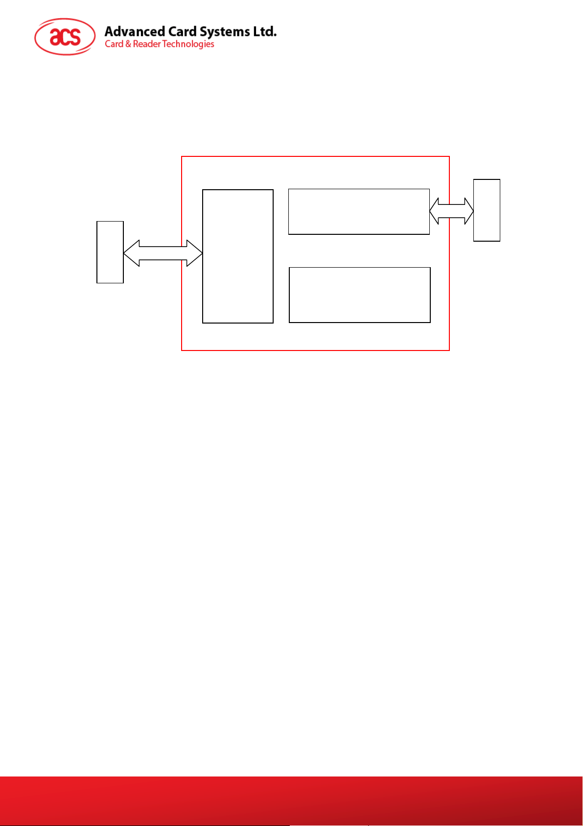
3.0. System Block Diagram .0. System Block Diagram
The USB Hub Controller is the communication interface between the PC and the MCU of the smart
The USB Hub Controller is the communication interface between the PC and the MCU of the smart
card and flash memory via USB port connection. The 1 GB flash memory is available for the end-user
card and flash memory via USB port connection. The 1 GB flash memory is available for the end-user
to use as storage. In Windows Explorer, the device is detected as a removable disk. The ACR100F is
to use as storage. In Windows Explorer, the device is detected as a removable disk. The ACR100F is
powered from the USB port without other external power supply.
powered from the USB port without other external power supply.
USB
Interface
Comp
uter
USB 2.0
Hub
Controller
Smart Card
Interface Circuit
1-GB Flash Memory
Smart Card
Figure 1: ACR1
00F System Block Diagram Figure 1: ACR100F System Block Diagram
ACR100F (CCID) Reference Manual
Document Title Here
Document Title Here
Version 3.00
Document Title Here
Page 5 of 18
info@acs.com.hk
info@acs.com.hk
www.acs.com.hk
www.acs.com.hk
Page 6

4.0. Power Supply
The ACR100F requires a voltage of 5 V DC, 100 mA regulated power supply. It gets the power supply
from the PC.
4.1. Status LED
Bicolor LED in front of the reader indicates the activation status of the smart card and flash memory
interface.
GREEN LED:
Flashing slowly (turns on 200 ms for every 2 seconds)
Indicates smart card interface part is powered up and in the standby state. Either the smart
card has not been inserted or the smart card has not been powered up (if it is inserted).
Lighting up
Indicates the smart card power is switched on, i.e., the smart card is activated.
RED LED:
Lighting up
Indicates a communication between ACR100F and flash memory.
ACR100F (CCID) Reference Manual
Document Title Here
Document Title Here
Version 3.00
Document Title Here
Page 6 of 18
info@acs.com.hk
info@acs.com.hk
www.acs.com.hk
www.acs.com.hk
Page 7

5.0. Smart Card Interface
The interface between the ACR100F and the inserted smart card follows the specifications of ISO
7816-3.
5.1. Smart Card Power Supply VCC (C1)
The current consumption of the inserted card must not be higher than 50 mA.
5.2. Programming Voltage VPP (C6)
According to ISO 7816-3, the smart card contact C6 (VPP) supplies the programming voltage to the
smart card. Since all common smart cards in the market are EEPROM based and do not require the
provision of an external programming voltage, the contact C6 (VPP) has been implemented as a
normal control signal in the ACR100F. The electrical specifications of this contact are identical to
those of the signal RST (at contact C2).
5.3. Card Type Selection
The controlling PC has to always select the card type through the proper command sent to the
ACR100F prior to activating the inserted card. This includes both the memory cards and MCU-based
cards. For MCU-based cards, the reader allows to select the preferred protocol, T=0 or T=1, however,
this selection is only accepted and carried out by the reader through the PPS when the card inserted
in the reader supports both protocol types. Whenever a MCU-based card supports only one protocol
type, T=0 or T=1, the reader automatically uses that protocol type, regardless of the protocol type
selected by the application.
5.4. Interface for Microcontroller-Based Cards
For microcontroller-based smart cards, only the contacts C1 (VCC), C2 (RST), C3 (CLK), C5 (GND)
and C7 (I/O) are used. A frequency of 4 MHz is applied to the CLK signal (C3).
5.5. Card Tearing Protection
The ACR100F provides a mechanism to protect the inserted card when it is suddenly withdrawn while
it is powered up. The power supply to the card and the signal lines between the ACR100F and the
card are immediately deactivated when the card is being removed. As a general rule, however, to
avoid any electrical damage, a card should only be removed from the reader while it is powered
down.
Note: The ACR100F never switches on the power supply to the inserted card by itself. This
must explicitly be done by the controlling computer through the proper command sent to the
reader.
ACR100F (CCID) Reference Manual
Document Title Here
Document Title Here
Version 3.00
Document Title Here
Page 7 of 18
info@acs.com.hk
info@acs.com.hk
www.acs.com.hk
www.acs.com.hk
Page 8

6.0. USB Interface
The connection of the ACR100F to a computer through a USB port follows a USB Standard.
6.1. Communication Parameters
The ACR100F is connected to a computer through USB as specified in the USB Specification. The
ACR100F is working in high-speed mode, i.e. 480 Mbps, for the flash memory and USB 1.1 full-speed
mode for smart card interface.
Pin Signal Function
1 V
2 D3 D+
4 GND
BUS
+5 V power supply for the reader
Differential signal transmits data between ACR100F and PC.
Differential signal transmits data between ACR100F and PC.
Reference voltage level for power supply
6.2. Endpoints
The ACR100F uses the following endpoints to communicate with the host computer:
Control Endpoint 0 For setup and control purposes
Bulk OUT Endpoint 1 For the command to be sent from host to Mass Storage Interface
(data packet size is 64 bytes)
Bulk IN Endpoint 1 For response to be sent from Mass Storage Interface to host (data
packet size is 64 bytes)
Bulk OUT Endpoint 2 For command to be sent from host to CCID Interface (data packet
size is 16 bytes)
Bulk IN Endpoint 2 For response to be sent from CCID Interface to host (data packet
ACR100F (CCID) Reference Manual
Document Title Here
Document Title Here
Version 3.00
size is 16 bytes)
Document Title Here
Page 8 of 18
info@acs.com.hk
info@acs.com.hk
www.acs.com.hk
www.acs.com.hk
Page 9

7.0. Communication Protocol
ACR100F interfaces with the host via USB connection. It is a compounded device consisting of two
interfaces: Chip Card Interface Device and Mass Storage.
The ACR100F Smart Card Interface shares the same core as the smart card interface of the ACR38
CCID. The Smart Card Interface will be identified as “ACR38-112c” once the reader FW is obtained.
(The command for this will be discussed later on). CCID covers all the protocols required for operating
smart cards and PIN.
The configurations and usage of USB endpoints on ACR100F Smart Card Interface shall follow CCID
Section 3. An overview is summarized below:
1. Control Commands are sent on control pipe (default pipe). These include class-specific
requests and USB standard requests. Commands that are sent on the default pipe report
information back to the host on the default pipe.
2. CCID Events are sent on th e interrupt pipe.
3. CCID Commands are sent on BULK-OUT endpoint. Each command sent to smart card
reader has an associated ending response. Some commands can also have intermediate
responses.
4. CCID Responses are sent on BULK-IN endpoint. All commands sent to the smart card reader
have to be sent synchronously. (i.e. bMaxCCIDBusySlots is equal to 1)
The supported CCID features by ACR100F smart card interface are indicated in its Class Descriptor:
Offset Field Size Value Description
0
1
2
4
5
6
10
14
18
19
23
27
28
32
36
bLength
bDescriptorTyp
e
bcdCCID
bMaxSlotIndex
bVoltageSuppor
t
dwProtocols
dwDefaultClock
dwMaximumClock
bNumClockSuppo
rted
dwDataRate
dwMaxDataRate
bNumDataRatesS
upported
dwMaxIFSD
dwSynchProtoco
ls
dwMechanical
36h
1
21h
1
0100h
2
00h
1
07h
1
00000003h
4
00000FA0h
4
00000FA0h
4
00h
1
00002A00h
4
0001F808h
4
00h
1
00000Feh
4
00000000h
4
00000000h
4
Size of this descriptor, in bytes.
CCID Functional Descriptor type.
CCID Specification Release Number in
Binary-Coded decimal.
One slot is available
The Smart card reader can supply 1.8V,
3.0V and 5.0V to its slot.
The Smart card reader supports T=0 and
T=1 Protocol
Default ICC clock frequency is 4MHz
Maximum supported ICC clock
frequency is 4MHz
Does not support manual setting of clock
frequency
Default ICC I/O data rate is 10752 bps
Maximum supported ICC I/O data rate is
344 kbps
Does not support manual setting of data
rates
Maximum IFSD supported by the smart
card reader for protocol T=1 is 254
The Smart card reader does not support
synchronous card
The Smart card reader does not support
special mechanical characteristics
ACR100F (CCID) Reference Manual
Document Title Here
Document Title Here
Version 3.00
Document Title Here
Page 9 of 18
info@acs.com.hk
info@acs.com.hk
www.acs.com.hk
www.acs.com.hk
Page 10

Offset Field Size Value Description
The Smart card reader supports the
following features:
Automatic ICC clock frequency
change according to
parameters
Automatic baud rate change
according to frequency and
FI,DI parameters
TPDU level exchange with the
smart card reader
Maximum message length accepted by
the smart card reader is 271 bytes
Insignificant for TPDU level exchanges
Insignificant for TPDU level exchanges
No LCD
No PIN Verification
Only 1 slot can be simultaneously busy
40
44
48
49
50
52
53
dwFeatures
dwMaxCCIDMessa
geLength
bClassGetRespo
nse
bClassEnvelope
wLCDLayout
bPINSupport
bMaxCCIDBusySl
ots
00010030h
4
0000010Fh
4
00h
1
00h
1
0000h
2
00h
1
01h
1
7.1. Command to the ACR100F (CCID)
In the normal operation, the ACR100F acts as a slave device with regard to the communication
between a computer and the reader. The communication is carried out in the form of successive
command-response exchanges. The computer transmits a command to the reader and receives a
response from the reader after the command has been executed. A new command can be transmitted
to the ACR100F only after the response to the previous command has been received.
There are two cases where the reader transmits data without having received a command from the
computer, namely, the Reset Message of the reader and the Card Status Message.
7.1.1. CCID Command Pipe Bulk-OUT Messages
The ACR100F shall follow the CCID Bulk-OUT Messages as specified in CCID section 4. In addition,
this specification defines some extended commands for operating additional features. This section
lists the CCID Bulk-OUT Messages to be supported by ACR100F.
7.1.1.1. PC_to_RDR_IccPowerOn
Activate the card slot and return ATR from the card.
Offset Field Size Value Description
0
1
2
5
6
7
bMessageTy
pe
dwLength
bSlot
bSeq
bPowerSele
ct
abRFU
1
4
1
1
1
2
62h
00000000
h
Size of extra bytes of this message
Identifies the slot number for this command
Sequence number for command
Voltage that is applied to the ICC
00h – Automatic Voltage Selection
01h – 5 volts
02h – 3 volts
Reserved for future use
The response to this message is the RDR_to_PC_DataBlock message and the data returned is the
Answer To Reset (ATR) data.
ACR100F (CCID) Reference Manual
Document Title Here
Document Title Here
Version 3.00
Document Title Here
Page 10 of 18
info@acs.com.hk
info@acs.com.hk
www.acs.com.hk
www.acs.com.hk
Page 11

7.1.1.2. PC_to_RDR_IccPowerOff
Deactivate the card slot.
Offset Field SizeValue Description
bMessageType
0
dwLength
1
bSlot
5
bSeq
6
abRFU
7
63h
1
00000000h
4
1
1
3
Size of extra bytes of this message
Identifies the slot number for this
command
Sequence number for command
Reserved for future use
The response to this message is the RDR_to_PC_SlotStatus message.
7.1.1.3. PC_to_RDR_GetSlotStatus
Get current status of the slot.
Offset Field Size Value Description
bMessageType
0
dwLength
1
bSlot
5
bSeq
6
abRFU
7
65h
1
00000000h
4
1
1
3
Size of extra bytes of this message
Identifies the slot number for this
command
Sequence number for command
Reserved for future use
The response to this message is the RDR_to_PC_SlotStatus message.
7.1.1.4. PC_to_RDR_XfrBlock
Transfer data block to the ICC.
Offset Field Size Value Description
0
1
5
6
7
8
10
bMessageType
dwLength
bSlot
bSeq
bBWI
wLevelParameter
abData
Byte
array
1
4
1
1
1
2
6Fh
0000h
Size of abData field of this message
Identifies the slot number for this command
Sequence number for command
Used to extend the CCIDs Block Waiting
Timeout for this current transfer. The CCID
will timeout the block after “this number
multiplied by the Block Waiting Time” has
expired.
RFU (TPDU exchange level)
Data block sent to the CCID. Data is sent
“as is” to the ICC (TPDU exchange level)
The response to this message is the RDR_to_PC_DataBlock message.
7.1.1.5. PC_to_RDR_GetParameters
Get slot parameters.
Offset Field Size Value Description
bMessageType
0
DwLength
1
BSlot
5
BSeq
6
1
4
1
1
6Ch
00000000
h
Size of extra bytes of this message
Identifies the slot number for this
command
Sequence number for command
ACR100F (CCID) Reference Manual
Document Title Here
Document Title Here
Version 3.00
Document Title Here
Page 11 of 18
info@acs.com.hk
info@acs.com.hk
www.acs.com.hk
www.acs.com.hk
Page 12

Offset Field Size Value Description
AbRFU
7
3
Reserved for future use
The response to this message is the RDR_to_PC_Parameters message.
7.1.1.6. PC_to_RDR_ResetParameters
Reset slot parameters to default value.
Offset Field Size Value Description
bMessageType
0
DwLength
1
BSlot
5
BSeq
6
AbRFU
7
6Dh
1
0000000
4
0h
1
1
3 Reserved for future use
Size of extra bytes of this message
Identifies the slot number for this
command
Sequence number for command
The response to this message is the RDR_to_PC_Parameters message.
7.1.1.7. PC_to_RDR_SetParameters
Set slot parameters.
Offset Field Size Value Description
0
1
5
6
7
8
10
bMessageType
dwLength
bSlot
bSeq
bProtocolNum
abRFU
abProtocolDat
aStructure
1
4
1
1
1
2
Byte
array
61h
Size of extra bytes of this message
Identifies the slot number for this command
Sequence number for command
Specifies what protocol data structure follows.
00h = Structure for protocol T=0
01h = Structure for protocol T=1
The following values are reserved for future
use.
80h = Structure for 2-wire protocol
81h = Structure for 3-wire protocol
82h = Structure for I2C protocol
Reserved for future use
Protocol Data Structure
Protocol Data Structure for Protocol T=0 (dwLength=00000005h)
Offset Field Size Value Description
bmFindexDinde
x
10
bmTCCKST0
11
bGuardTimeT0
12
13
ACR100F (CCID) Reference Manual
Document Title Here
Document Title Here
Version 3.00
bWaitingInteg
erT0
B7-4 – FI – Index into the table 7 in ISO/IEC
7816-3:1997 selecting a clock rate conversion
1
B0 – 0b, B7-2 – 000000b
1
Extra Guardtime between two characters.
1
1
factor
B3-0 – DI - Index into the table 8 in
ISO/IEC 7816-3:1997 selecting a baud rate
conversion factor
B1 – Convention used (b1=0 for direct, b1=1
for inverse) Note: The CCID ignores this bit.
Add 0 to 254 etu to the normal guardtime of
12 etu. FFh is the same as 00h.
WI for T=0 used to define WWT
Document Title Here
Page 12 of 18
info@acs.com.hk
info@acs.com.hk
www.acs.com.hk
www.acs.com.hk
Page 13

Offset Field Size Value Description
ICC Clock Stop Support
00h = Stopping the Clock is not allowed
14
bClockStop
1
01h = Stop with Clock signal Low
02h = Stop with Clock signal High
03h = Stop with Clock either High or Low
Protocol Data Structure for Protocol T=1 (dwLength=00000007h)
Offset Field Size Value Description
B7-4 – FI – Index into the table 7 in ISO/IEC
7816-3:1997 selecting a clock rate conversion
factor
B3-0 – DI - Index into the table 8 in
ISO/IEC 7816-3:1997 selecting a baud rate
conversion factor
B7-2 – 000100b
B0 – Checksum type (b0=0 for LRC, b0=1 for
CRC)
B1 – Convention used (b1=0 for direct, b1=1 for
inverse) Note: The CCID ignores this bit.
Extra Guardtime (0 to 254 etu between two
characters). If value is FFh, then guardtime is
reduced by 1 etu.
B7-4 = BWI values 0-9 valid
B3-0 = CWI values 0-Fh valid
ICC Clock Stop Support
00h = Stopping the Clock is not allowed
01h = Stop with Clock signal Low
02h = Stop with Clock signal High
03h = Stop with Clock either High or Low
Size of negotiated IFSC
Only support NAD = 00h
10
11
12
13
14
15
16
bmFindexDin
dex
BmTCCKST1
BGuardTimeT
1
BwaitingInt
egerT1
bClockStop
bIFSC
bNadValue
1
1
1
1
1
1
00h
1
The response to this message is the RDR_to_PC_Parameters message.
7.1.2. CCID Bulk-IN Messages
The Bulk-IN messages are used in response to the Bulk-OUT messages. ACR100F shall follow the
CCID Bulk-IN Messages as specified in section 4. This section lists the CCID Bulk-IN Messages to
be supported by ACR100F.
7.1.2.1. RDR_to_PC_DataBlock
This message is sent by the smart card reader in response to PC_to_RDR_IccPowerOn,
PC_to_RDR_XfrBlock and PC_to_RDR_Secure messages.
Offset Field Size Value Description
0
1
5
6
7
8
9
10
bMessageType
dwLength
bSlot
bSeq
bStatus
bError
bChainParame
ter
abData
1
4
1
1
1
1
1
Byte
array
80h
00h
Indicates that a data block is being sent from
the CCID
Size of extra bytes of this message
Same value as in Bulk-OUT message
Same value as in Bulk-OUT message
Slot status register as defined in CCID section
4.2.1
Slot error register as defined in CCID section
4.2.1 and this specification section 5.2.8
RFU (TPDU exchange level)
This field contains the data returned
by the CCID
Page 13 of 18
ACR100F (CCID) Reference Manual
Document Title Here
Document Title Here
Version 3.00
Document Title Here
info@acs.com.hk
info@acs.com.hk
www.acs.com.hk
www.acs.com.hk
Page 14

7.1.2.2. RDR_to_PC_SlotStatus
This message is sent by the smart card reader in response to PC_to_RDR_IccPowerOff,
PC_to_RDR_GetSlotStatus, PC_to_RDR_Abort messages and Class specific ABORT request.
Offset Field Size Value Description
0
1
5
6
7
8
9
bMessageTy
pe
dwLength
bSlot
bSeq
bStatus
bError
bClockStat
us
1
4
1
1
1
1
1
81h
0000000
0h
Size of extra bytes of this message
Same value as in Bulk-OUT message
Same value as in Bulk-OUT message
Slot status register as defined in CCID section
4.2.1
Slot error register as defined in CCID section
4.2.1 and this specification section 5.2.8
value =
00h Clock running
01h Clock stopped in state L
02h Clock stopped in state H
03h Clock stopped in an unknown state
All other values are RFU.
ACR100F (CCID) Reference Manual
Document Title Here
Document Title Here
Version 3.00
Document Title Here
Page 14 of 18
info@acs.com.hk
info@acs.com.hk
www.acs.com.hk
www.acs.com.hk
Page 15

7.1.2.3. RDR_to_PC_Parameters
This message is sent by the smart card reader in response to PC_to_RDR_GetParameters,
PC_to_RDR_ResetParameters and PC_to_RDR_SetParameters messages.
Offset Field Size Value Description
0
1
5
6
7
8
9
10
bMessageType
dwLength
bSlot
bSeq
bStatus
bError
bProtocolNum
abProtocolData
Structure
82h
1
Size of extra bytes of this message
4
Same value as in Bulk-OUT message
1
Same value as in Bulk-OUT message
1
Slot status register as defined in CCID section
1
Slot error register as defined in CCID section
1
Specifies what protocol data structure follows.
1
Byt
Protocol Data Structure as summarized in
e
arra
y
4.2.1
4.2.1 and this specification section 5.2.8
00h = Structure for protocol T=0
01h = Structure for protocol T=1
The following values are reserved for future
use.
80h = Structure for 2-wire protocol
81h = Structure for 3-wire protocol
82h = Structure for I2C protocol
section 5.2.3.
7.1.3. Commands Accessed via PC_to_RDR_XfrBlock
7.1.3.1. GET_READER_INFORMATION
This command returns relevant information about the particular smart card reader model and the
current operating status such as the firmware revision number, the maximum data length of a
command and response, the supported card types, and whether a card is inserted and powered up or
not.
Note: This command can only be used after the logical smart card reader communication has
been established using the SCardConnect( ) API. For details of ScardConnect( ) API,
please refer to PC/SC specification.
Pseudo-APDU
CLA INS P1 P2 Lc
FF H 09 H 00 H 00 H 10 H
Command format (abData field in the PC_to_RDR_XfrBlock)
FIRMWARE MAX
_C
MAX
_R
C_TY
PE
C_SEL C_ST
AT
Response data format (abData field in the RDR_to_PC_DataBlock)
Page 15 of 18
ACR100F (CCID) Reference Manual
Document Title Here
Document Title Here
Version 3.00
Document Title Here
info@acs.com.hk
info@acs.com.hk
www.acs.com.hk
www.acs.com.hk
Page 16

FIRMWARE 10 bytes data for firmware version
MAX_C The maximum number of command data bytes.
MAX_R The maximum number of data bytes that can be requested to be transmitted in a
response.
C_TYPE The card types supported by the smart card reader. This data field is a bitmap with
each bit representing a particular card type. A bit set to '1' means the co rresponding
card type is supported by the reader and can be selected with the
SELECT_CARD_TYPE command. The bit assignment is as follows:
Byte 1 2
card type
See Appendix A.1 for the correspondence between these bits and the respective card
types.
C_SEL The currently selected card type. A value of 00H means that no card type has been
selected.
C_STAT Indicates whether a card is physically inserted in the reader an d whether the card is
powered up:
00
: no card inserted
H
01
: card inserted, not powered up
H
03
: card powered up
H
F E D C B A 9 8 7 6 5 4 3 2 1 0
7.2. Mass Storage
Mass Storage Device Class specifies all the protocols required for data transaction between the Host
(computer) and storage devices. The configurations and usage of USB endpoints on ACR100 shall
follow Mass Storage Class Bulk-Only Transport in Section 3 (Protocol Code) of the USB Mass
Storage Device Specification. This document is available at: www.usb.org.
An overview of this specification is summarized below:
1. Control Commands are sent on control pipe (default pipe). It is shared with the CCID
interface.
2. Data-Out Command Protocol uses the BULK-OUT endpoint to transfer data from the host to
the device.
3. Data-In Command Protocol uses the BULK-IN endpoint to transfer data from the device or to
return status about the device.
ACR100F (CCID) Reference Manual
Document Title Here
Document Title Here
Version 3.00
Document Title Here
Page 16 of 18
info@acs.com.hk
info@acs.com.hk
www.acs.com.hk
www.acs.com.hk
Page 17

Appendix A. Supported Card Types
The following table is a list of the card types returned by GET_READER_INFORMATION corresponding
with the respective card type code:
Card type code Card Type
00H
01H
02H
03H
04H
05H
06H
07H
08H
09H
0CH
0DH
Auto-select T=0 or T=1 communication protocol
I2C memory card (1k, 2k, 4k, 8k and 16k bits)
I2C memory card (32k, 64k, 128k, 256k, 512k and 1024k bits)
Atmel AT88SC153 secure memory card
Atmel AT88SC1608 secure memory card
Infineon SLE4418 and SLE4428
Infineon SLE4432 and SLE4442
Infineon SLE4406, SLE4436 and SLE5536
Infineon SLE4404
Atmel AT88SC101, AT88SC102 and AT88SC1003
MCU-based cards with T=0 communication protocol
MCU-based cards with T=1 communication protocol
ACR100F (CCID) Reference Manual
Document Title Here
Document Title Here
Version 3.00
Document Title Here
Page 17 of 18
info@acs.com.hk
info@acs.com.hk
www.acs.com.hk
www.acs.com.hk
Page 18

Appendix B. Response Status Codes
The following table is a list of the error codes that may be returned by the ACR38:
Error Code Status
FFH
FEH
FDH
FCH
FBH
F8H
F7H
F6H
F5H
F4H
F3H
F2H
E0H
SLOTERROR_CMD_ABORTED
SLOTERROR_ICC_MUTE
SLOTERROR_XFR_PARITY_ERROR
SLOTERROR_XFR_OVERRUN
SLOTERROR_HW_ERROR
SLOTERROR_BAD_ATR_TS
SLOTERROR_BAD_ATR_TCK
SLOTERROR_ICC_PROTOCOL_NOT_SUPPORTED
SLOTERROR_ICC_CLASS_NOT_SUPPORTED
SLOTERROR_PROCEDURE_BYTE_CONFLICE
SLOTERROR_DEACTIVATED_PROTOCOL
SLOTERROR_BUSY_WITH_AUTO_SEQUENCE
SLOTERROR_CMD_SLOT_BUSY
ACR100F (CCID) Reference Manual
Document Title Here
Document Title Here
Version 3.00
Document Title Here
Page 18 of 18
info@acs.com.hk
info@acs.com.hk
www.acs.com.hk
www.acs.com.hk
 Loading...