

Page 1

Acronis Storage 2.4
Administrator’s Guide
January 15, 2019
Page 2

Copyright Statement
Acronis International GmbH, 2002-2016. All rights reserved.
”Acronis” and ”Acronis Secure Zone” are registered trademarks of Acronis International GmbH.
”Acronis Compute with Confidence”, ”Acronis Startup Recovery Manager”, ”Acronis Active Restore”,
”Acronis Instant Restore” and the Acronis logo are trademarks of Acronis International GmbH.
Linux is a registered trademark of Linus Torvalds.
VMware and VMware Ready are trademarks and/or registered trademarks of VMware, Inc. in the United States and/or other jurisdictions.
Windows and MS-DOS are registered trademarks of Microsoft Corporation.
All other trademarks and copyrights referred to are the property of their respective owners.
Distribution of substantively modified versions of this document is prohibited without the explicit permission of the copyright holder.
Distribution of this work or derivative work in any standard (paper) book form for commercial purposes is prohibited unless prior permission is
obtained from the copyright holder.
DOCUMENTATION IS PROVIDED ”AS IS” AND ALL EXPRESS OR IMPLIED CONDITIONS, REPRESENTATIONS AND WARRANTIES, INCLUDING ANY IMPLIED
WARRANTY OF MERCHANTABILITY, FITNESS FOR A PARTICULAR PURPOSE OR NON-INFRINGEMENT, ARE DISCLAIMED, EXCEPT TO THE EXTENT THAT
SUCH DISCLAIMERS ARE HELD TO BE LEGALLY INVALID.
Third party code may be provided with the Software and/or Service. The license terms for such third parties are detailed in the license.txt file located in
the root installation directory. You can always find the latest up-to-date list of the third party code and the associated license terms used with the
Software and/or Service at http://kb.acronis.com/content/7696
Acronis patented technologies
Technologies, used in this product, are covered and protected by one or more U.S. Patent Numbers: 7,047,380; 7,275,139; 7,281,104; 7,318,135;
7,353,355; 7,366,859; 7,475,282; 7,603,533; 7,636,824; 7,650,473; 7,721,138; 7,779,221; 7,831,789; 7,886,120; 7,895,403; 7,934,064; 7,937,612; 7,949,635;
7,953,948; 7,979,690; 8,005,797; 8,051,044; 8,069,320; 8,073,815; 8,074,035; 8,145,607; 8,180,984; 8,225,133; 8,261,035; 8,296,264; 8,312,259; 8,347,137;
8,484,427; 8,645,748; 8,732,121 and patent pending applications.
Page 3

Contents
1. Introduction . . . . . . . . . . . . . . . . . . . . . . . . . . . . . . . . . . . . . . . . . . . . . . . . . . . . . 1
1.1 About Acronis Storage . . . . . . . . . . . . . . . . . . . . . . . . . . . . . . . . . . . . . . . . . . . . 1
2. Managing Acronis Storage . . . . . . . . . . . . . . . . . . . . . . . . . . . . . . . . . . . . . . . . . . . . 2
2.1 Configuring Node Network Interfaces . . . . . . . . . . . . . . . . . . . . . . . . . . . . . . . . . . . 2
2.1.1 Setting Up Network Bonding . . . . . . . . . . . . . . . . . . . . . . . . . . . . . . . . . . . 7
2.1.2 Setting Up VLAN Interfaces . . . . . . . . . . . . . . . . . . . . . . . . . . . . . . . . . . . . 10
2.2 Creating the Storage Cluster . . . . . . . . . . . . . . . . . . . . . . . . . . . . . . . . . . . . . . . . 11
2.2.1 Creating the Storage Cluster on the First Node . . . . . . . . . . . . . . . . . . . . . . . . 12
2.2.2 Adding Nodes to Storage Cluster . . . . . . . . . . . . . . . . . . . . . . . . . . . . . . . . . 14
2.2.3 Assigning Disk Roles Manually . . . . . . . . . . . . . . . . . . . . . . . . . . . . . . . . . . 16
2.3 Releasing Nodes from the Storage Cluster . . . . . . . . . . . . . . . . . . . . . . . . . . . . . . . . 19
2.4 Removing Nodes from the Unassigned List . . . . . . . . . . . . . . . . . . . . . . . . . . . . . . . . 20
2.5 Managing Tier Encryption . . . . . . . . . . . . . . . . . . . . . . . . . . . . . . . . . . . . . . . . . . 21
2.6 Managing Users . . . . . . . . . . . . . . . . . . . . . . . . . . . . . . . . . . . . . . . . . . . . . . . . 22
2.6.1 Creating User Accounts . . . . . . . . . . . . . . . . . . . . . . . . . . . . . . . . . . . . . . 22
2.6.2 Managing User Accounts . . . . . . . . . . . . . . . . . . . . . . . . . . . . . . . . . . . . . 23
2.6.3 Adding LDAP or Active Directory Users . . . . . . . . . . . . . . . . . . . . . . . . . . . . . 24
2.7 Managing Updates . . . . . . . . . . . . . . . . . . . . . . . . . . . . . . . . . . . . . . . . . . . . . . 28
2.7.1 Upgrading to Acronis Software-Defined Infrastructure 2.5 . . . . . . . . . . . . . . . . . . 29
2.8 Allowing root Access to Cluster Nodes Over SSH . . . . . . . . . . . . . . . . . . . . . . . . . . . . 30
2.9 Backing Up and Restoring Management Database . . . . . . . . . . . . . . . . . . . . . . . . . . . 31
2.9.1 Restoring Management Database from Backup . . . . . . . . . . . . . . . . . . . . . . . . 32
2.10 Enabling Management Panel High Availability . . . . . . . . . . . . . . . . . . . . . . . . . . . . . . 33
2.11 Accessing the Management Panel via SSL . . . . . . . . . . . . . . . . . . . . . . . . . . . . . . . . 36
2.12 Managing Licenses . . . . . . . . . . . . . . . . . . . . . . . . . . . . . . . . . . . . . . . . . . . . . . 37
i
Page 4

2.12.1 Installing License Keys . . . . . . . . . . . . . . . . . . . . . . . . . . . . . . . . . . . . . . . 37
2.12.2 Installing SPLA Licenses . . . . . . . . . . . . . . . . . . . . . . . . . . . . . . . . . . . . . . 39
2.13 Connecting Remote iSCSI Devices to Storage Cluster Nodes . . . . . . . . . . . . . . . . . . . . . . 40
2.13.1 Assigning Disk Roles To Remote iSCSI Devices . . . . . . . . . . . . . . . . . . . . . . . . . 41
3. Monitoring the Storage Cluster . . . . . . . . . . . . . . . . . . . . . . . . . . . . . . . . . . . . . . . . . 42
3.1 Monitoring Storage Cluster Status . . . . . . . . . . . . . . . . . . . . . . . . . . . . . . . . . . . . . 42
3.2 Monitoring Storage Cluster Space . . . . . . . . . . . . . . . . . . . . . . . . . . . . . . . . . . . . . 42
3.2.1 Physical Space Chart . . . . . . . . . . . . . . . . . . . . . . . . . . . . . . . . . . . . . . . . 43
3.2.2 Logical Space Chart . . . . . . . . . . . . . . . . . . . . . . . . . . . . . . . . . . . . . . . . . 43
3.2.2.1 Understanding Logical Space . . . . . . . . . . . . . . . . . . . . . . . . . . . . . 44
3.2.3 Monitoring Chunk Status and Replication . . . . . . . . . . . . . . . . . . . . . . . . . . . . 44
3.2.4 Monitoring Storage Cluster Services . . . . . . . . . . . . . . . . . . . . . . . . . . . . . . . 45
3.2.5 Monitoring Storage Cluster I/O Activity . . . . . . . . . . . . . . . . . . . . . . . . . . . . . 46
3.3 Monitoring Storage Cluster Objects via SNMP . . . . . . . . . . . . . . . . . . . . . . . . . . . . . . 47
3.3.1 Enabling SNMP Access . . . . . . . . . . . . . . . . . . . . . . . . . . . . . . . . . . . . . . . 48
3.3.2 Accessing Storage Cluster Information Objects via SNMP . . . . . . . . . . . . . . . . . . 49
3.3.2.1 Listening to SNMP Traps . . . . . . . . . . . . . . . . . . . . . . . . . . . . . . . 49
3.3.3 Monitoring the Storage Cluster with Zabbix . . . . . . . . . . . . . . . . . . . . . . . . . . 50
3.3.4 Storage Cluster Objects and Traps . . . . . . . . . . . . . . . . . . . . . . . . . . . . . . . . 54
4. Monitoring Storage Cluster Nodes . . . . . . . . . . . . . . . . . . . . . . . . . . . . . . . . . . . . . . . 57
4.1 Storage Cluster Node Statuses . . . . . . . . . . . . . . . . . . . . . . . . . . . . . . . . . . . . . . . 57
4.2 Monitoring Storage Cluster Node Performance . . . . . . . . . . . . . . . . . . . . . . . . . . . . . 58
4.2.1 Monitoring Storage Cluster Node Disks . . . . . . . . . . . . . . . . . . . . . . . . . . . . . 59
4.2.1.1 Monitoring the S.M.A.R.T. Status of Node Disks . . . . . . . . . . . . . . . . . . 60
4.3 Monitoring Node Network . . . . . . . . . . . . . . . . . . . . . . . . . . . . . . . . . . . . . . . . . 60
5. Viewing Alerts and Audit Log and Sending E-mail Notifications . . . . . . . . . . . . . . . . . . . . . 61
5.1 Viewing Alerts . . . . . . . . . . . . . . . . . . . . . . . . . . . . . . . . . . . . . . . . . . . . . . . . . 61
5.2 Viewing Audit Log . . . . . . . . . . . . . . . . . . . . . . . . . . . . . . . . . . . . . . . . . . . . . . . 62
5.3 Sending E-mail Notifications . . . . . . . . . . . . . . . . . . . . . . . . . . . . . . . . . . . . . . . . 63
6. Exporting Storage Cluster Data . . . . . . . . . . . . . . . . . . . . . . . . . . . . . . . . . . . . . . . . . 66
6.1 Exporting Data via iSCSI . . . . . . . . . . . . . . . . . . . . . . . . . . . . . . . . . . . . . . . . . . . 66
6.1.1 Creating iSCSI Targets . . . . . . . . . . . . . . . . . . . . . . . . . . . . . . . . . . . . . . . 67
6.1.1.1 Performance Tips . . . . . . . . . . . . . . . . . . . . . . . . . . . . . . . . . . . . 69
ii
Page 5

6.1.2 Listing, Stopping, and Deleting iSCSI Targets . . . . . . . . . . . . . . . . . . . . . . . . . . 69
6.1.3 Configuring iSCSI Targets . . . . . . . . . . . . . . . . . . . . . . . . . . . . . . . . . . . . . 69
6.1.3.1 Listing LUNs . . . . . . . . . . . . . . . . . . . . . . . . . . . . . . . . . . . . . . . 71
6.1.3.2 Adding LUNs . . . . . . . . . . . . . . . . . . . . . . . . . . . . . . . . . . . . . . 71
6.1.3.3 Configuring LUNs . . . . . . . . . . . . . . . . . . . . . . . . . . . . . . . . . . . . 73
6.1.3.4 Deleting LUNs . . . . . . . . . . . . . . . . . . . . . . . . . . . . . . . . . . . . . . 73
6.1.4 Managing iSCSI Users . . . . . . . . . . . . . . . . . . . . . . . . . . . . . . . . . . . . . . . 73
6.1.4.1 Creating CHAP Accounts for iSCSI Targets . . . . . . . . . . . . . . . . . . . . . 73
6.1.4.2 Creating iSCSI Targets Bound to CHAP Accounts . . . . . . . . . . . . . . . . . 74
6.1.4.3 Changing CHAP Account Passwords . . . . . . . . . . . . . . . . . . . . . . . . . 75
6.2 Exporting Data via S3 . . . . . . . . . . . . . . . . . . . . . . . . . . . . . . . . . . . . . . . . . . . . 76
6.2.1 S3 Storage Infrastructure Overview . . . . . . . . . . . . . . . . . . . . . . . . . . . . . . . 77
6.2.2 Planning the S3 Cluster . . . . . . . . . . . . . . . . . . . . . . . . . . . . . . . . . . . . . . 79
6.2.3 Sample S3 Storage . . . . . . . . . . . . . . . . . . . . . . . . . . . . . . . . . . . . . . . . . 79
6.2.4 Creating the S3 Cluster . . . . . . . . . . . . . . . . . . . . . . . . . . . . . . . . . . . . . . . 81
6.2.5 Managing S3 Users . . . . . . . . . . . . . . . . . . . . . . . . . . . . . . . . . . . . . . . . . 85
6.2.5.1 Adding S3 Users . . . . . . . . . . . . . . . . . . . . . . . . . . . . . . . . . . . . 86
6.2.5.2 Managing S3 Access Key Pairs . . . . . . . . . . . . . . . . . . . . . . . . . . . . 87
6.2.6 Managing S3 Buckets . . . . . . . . . . . . . . . . . . . . . . . . . . . . . . . . . . . . . . . . 89
6.2.6.1 Listing S3 Bucket Contents . . . . . . . . . . . . . . . . . . . . . . . . . . . . . . 89
6.2.6.2 Managing Acronis Notary in S3 Buckets . . . . . . . . . . . . . . . . . . . . . . . 90
6.2.7 Best Practices for Using S3 in Acronis Storage . . . . . . . . . . . . . . . . . . . . . . . . . 91
6.2.7.1 S3 Bucket and Key Naming Policies . . . . . . . . . . . . . . . . . . . . . . . . . 91
6.2.7.2 Improving Performance of PUT Operations . . . . . . . . . . . . . . . . . . . . 92
6.2.8 Replicating S3 Data Between Datacenters . . . . . . . . . . . . . . . . . . . . . . . . . . . 92
6.2.9 Monitoring S3 Access Points . . . . . . . . . . . . . . . . . . . . . . . . . . . . . . . . . . . 94
6.2.10 Releasing Nodes from S3 Clusters . . . . . . . . . . . . . . . . . . . . . . . . . . . . . . . . 94
6.2.11 Supported Amazon S3 Features . . . . . . . . . . . . . . . . . . . . . . . . . . . . . . . . . 95
6.2.11.1 Supported Amazon S3 REST Operations . . . . . . . . . . . . . . . . . . . . . . 95
6.2.11.2 Supported Amazon Request Headers . . . . . . . . . . . . . . . . . . . . . . . . 97
6.2.11.3 Supported Amazon Response Headers . . . . . . . . . . . . . . . . . . . . . . . 97
6.2.11.4 Supported Amazon Error Response Headers . . . . . . . . . . . . . . . . . . . 98
6.2.11.5 Supported Authentication Scheme and Methods . . . . . . . . . . . . . . . . . 99
6.3 Exporting Data via NFS . . . . . . . . . . . . . . . . . . . . . . . . . . . . . . . . . . . . . . . . . . . . 99
6.3.1 Setting Up an NFS Cluster . . . . . . . . . . . . . . . . . . . . . . . . . . . . . . . . . . . . .100
iii
Page 6

6.3.2 Creating NFS Shares . . . . . . . . . . . . . . . . . . . . . . . . . . . . . . . . . . . . . . . . 100
6.3.3 Creating NFS Exports . . . . . . . . . . . . . . . . . . . . . . . . . . . . . . . . . . . . . . . .101
6.3.3.1 Creating the Root Export . . . . . . . . . . . . . . . . . . . . . . . . . . . . . . .101
6.3.3.2 Creating User Exports . . . . . . . . . . . . . . . . . . . . . . . . . . . . . . . . .102
6.3.4 Setting Up User Authentication and Authorization . . . . . . . . . . . . . . . . . . . . . . 103
6.3.4.1 Authenticating NFS Share Users with Kerberos . . . . . . . . . . . . . . . . . .104
6.3.4.2 Authorizing NFS Export Users with LDAP . . . . . . . . . . . . . . . . . . . . . .105
6.4 Connecting Acronis Backup Software to Storage Backends via Acronis Backup Gateway . . . . . 105
6.4.1 Understanding the Infrastructure . . . . . . . . . . . . . . . . . . . . . . . . . . . . . . . .106
6.4.2 Connecting to the Local Storage Cluster via Acronis Backup Gateway . . . . . . . . . . .107
6.4.3 Connecting to External NFS Shares via Acronis Backup Gateway . . . . . . . . . . . . . .112
6.4.4 Connecting to Public Cloud Storage via Acronis Backup Gateway . . . . . . . . . . . . . .116
6.4.5 Migrating Backups from Older Acronis Solutions . . . . . . . . . . . . . . . . . . . . . . .120
6.4.5.1 Migrating Backups from Acronis Storage 1.5 . . . . . . . . . . . . . . . . . . . .121
6.4.5.2 Migrating Backups from Acronis Storage Gateway 1.6 and 1.7 (NFS) . . . . . .125
6.4.6 Monitoring Acronis Backup Gateway . . . . . . . . . . . . . . . . . . . . . . . . . . . . . . 129
6.4.7 Releasing Nodes from Acronis Backup Gateway . . . . . . . . . . . . . . . . . . . . . . . .131
iv
Page 7

CHAPTER 1
Introduction
To support the growing demand for both high performance and high data availability, modern data centers
need a fast, flexible storage solution. Existing solutions, however, are often difficult to manage and maintain,
or not flexible enough (e.g., local RAID arrays), or too expensive (e.g., storage area networks).
Acronis Storage is designed to solve these issues. It can run on commodity hardware, so no significant
infrastructure investments are needed. It is also easy to set up and grow on demand.
1.1 About Acronis Storage
Acronis Storage is a software-defined storage solution that allows you to quickly and easily transform
low-cost commodity storage hardware and network equipment into protected enterprise-grade storage like
SAN or NAS.
Acronis Storage is optimized for storing large amounts of data and provides data redundancy (replication
and erasure coding), high availability, self-healing, and storage sharing.
In Acronis Storage, user data is stored on organized clusters of servers in the form of fixed-size chunks.
These chunks are automatically replicated and distributed across available servers in the cluster to ensure
high availability of user data.
Cluster storage space can be exported through access points like iSCSI, S3, NFS, or Acronis Backup Gateway.
1
Page 8

CHAPTER 2
Managing Acronis Storage
To start managing Acronis Storage, log in to the management panel as admin (or superadmin) and make
sure that storage nodes are shown on the NODES screen.
The first step to perform, before you can create the cluster, is to create the internal and public networks
required by Acronis Storage. You can do that by configuring the network interfaces of all nodes. Having
created the networks, you can proceed to creating storage clusters.
2.1 Configuring Node Network Interfaces
As described in Planning Network in the Installation Guide, Acronis Storage requires one internal network
for node traffic and one public network for exporting the storage space. You need to create these networks
by assigning correct network roles to network interfaces on each node.
Important: To be able to create a cluster, you will need to assign a storage role to a node’s network
interface.
To assign a network role to a network interface, do the following:
1. On the NODES screen, click the node to configure the network interface(s) of.
2
Page 9

2.1. Configuring Node Network Interfaces
2. On the node overview screen, click NETWORK.
3
Page 10

3. Select a network interface and click Configure.
4. On the Configure screen, do one of the following:
Chapter 2. Managing Acronis Storage
• To obtain the IP address, DNS, and routing settings from the DHCP server, select Automatically
(DHCP).
• To obtain just the IP address from the DHCP server, select Automatically (DHCP address only).
• To specify the IP address manually, select Manual and add the IP address.
Warning: Dynamic IP address allocation will cause network issues as soon as the IP addresses of
cluster nodes will change. Configure static IP addresses from the start or as soon as possible.
4
Page 11

2.1. Configuring Node Network Interfaces
5. If necessary, set up a gateway and a DNS server.
6. If you have set a custom maximum transmission unit (MTU) on the network hardware, set the same
value in the corresponding field.
Warning: Setting a custom MTU in management panel prior to configuring it on the network
hardware will result in network failure on the node and require manual resetting. Setting an MTU
that differs from the one configured on the network hardware may result in network outage or
poor performance.
7. Click Done to return to the list of network interfaces, do not change the selection, and click Choose role.
8. On the
Choose roles
panel, select roles to assign to the network interface (for details, see the
5
Page 12

Installation Guide).
Chapter 2. Managing Acronis Storage
9. If you need to open specific ports on a network interface with public roles, do the following:
9.1. Click Configure.
6
Page 13

2.1. Configuring Node Network Interfaces
9.2. On the Configure custom role panel, create custom roles: click Add and specify role names and
ports. Custom roles can later be assigned to any network interface in a cluster.
To remove a custom role, make sure it is not assigned to any interface, select it, and click Remove.
9.3. Click Done to return to the Choose roles panel.
10. Select the required roles and click Done to assign them.
2.1.1 Setting Up Network Bonding
Bonding multiple network interfaces is optional but provides the following benefits:
• High network availability. If one of the interfaces fails, the traffic will be automatically routed through
the working interface(s).
• Higher network performance. For example, two bonded Gigabit interfaces will deliver the throughput
of about 1.7 Gbit/s or up to 200 MB/s. For a storage node, the required number of network interfaces to
bond may depend on the number of disks. For example, an HDD can deliver data at speeds of up to 1
7
Page 14

Chapter 2. Managing Acronis Storage
Gbps.
To create a bond, do the following:
1. On the NODES screen, click the node to bond the network interfaces on.
2. On the node overview screen, click NETWORK.
3. In the NETWORK list, check network interfaces to bond, and click Create bonding in the menu to the
right.
4. On the Configure Bonding panel, select the bonding type from the drop-down list. The balance-xor
type is selected by default and recommended for both fault tolerance and good performance.
8
Page 15

2.1. Configuring Node Network Interfaces
5. Set up network parameters as described in step 4 in Configuring Node Network Interfaces on page 2 and
click PROCEED.
6. On the Choose roles panel, select roles to assign to the bonding network interface (for details, see the
Installation Guide).
9
Page 16

Chapter 2. Managing Acronis Storage
7. Click Done.
2.1.2 Setting Up VLAN Interfaces
To set up a VLAN network interface, do the following:
1. On the NODES screen, click the node on which to configure VLAN.
2. On the node overview screen, click NETWORK.
3. Select a network interface and click Create VLAN.
4. On the Configure VLAN panel, specify a number for VLAN, add an IP address, and, if necessary, set up a
10
Page 17

2.2. Creating the Storage Cluster
gateway and a DNS server.
5. Click Proceed to create a VLAN interface.
2.2 Creating the Storage Cluster
To create a storage cluster, you need to create a basic storage cluster on one (first) node, then populate it
with more nodes.
11
Page 18

Chapter 2. Managing Acronis Storage
Important: To be able to create the storage cluster, you will need to assign the storage role to a
node’s network interface.
If you have remote iSCSI devices you wish to connect to cluster nodes, you can configure them prior to
cluster creation as described in Connecting Remote iSCSI Devices to Storage Cluster Nodes on page 40.
2.2.1 Creating the Storage Cluster on the First Node
1. Open the NODES screen and click a node in the UNASSIGNED list.
2. On the node overview screen, click Create cluster.
3. In the Cluster field, type a name for the cluster. The name may only contain Latin letters (a-z, A-Z),
numbers (0-9), underscores (“_”) and dashes (“-”).
12
Page 19

2.2. Creating the Storage Cluster
4. Make sure a network interface with the role Storage is selected from the Storage interface drop-down
list.
Note: If necessary, click the cogwheel icon and assign the required role(s) to network interfaces
on the Network Configuration screen.
5. If required, enable data encryption. To do this, check the Encryption box (see Managing Tier Encryption
on page 21) and proceed to create the cluster. Encryption will be enabled for all tiers by default.
To enable encryption for particular tiers, click the cogwheel icon to open the Encryption Configuration
panel, select tiers to encrypt, and click Done.
13
Page 20

Chapter 2. Managing Acronis Storage
Note: You can later disable encryption for new chunk services (CS) on the SETTINGS > Advanced
settings panel.
6. Click New cluster to have Acronis Storage assign the roles to disks automatically. Alternatively, click
Advanced configuration to assign the roles to each drive manually and tweak other settings.
You can monitor cluster creation progress in the HEALTHY list of the INFRASTRUCTURE > Nodes screen.
The creation might take some time depending on the number of disks to be configured. Once the automatic
configuration is complete, the cluster is created.
2.2.2 Adding Nodes to Storage Cluster
To add an unassigned node to a cluster, do the following:
1. On the NODES screen, click an unassigned node.
14
Page 21

2.2. Creating the Storage Cluster
2. On the node overview screen, click Join cluster.
3. Make sure a configured network interface with a storage role is selected from the Storage interface
drop-down list.
Note: If the network was not previously configured, click the cogwheel icon and, on the
Network Configuration screen, configure a storage role for a network interface.
15
Page 22

Chapter 2. Managing Acronis Storage
4. Click Join cluster to have Acronis Storage assign the roles to disks automatically and add the node to
the current cluster. Alternatively, click Advanced configuration to assign the roles to each drive
manually (see Assigning Disk Roles Manually on page 16).
2.2.3 Assigning Disk Roles Manually
If you clicked Advanced configuration while creating a cluster or adding nodes to it, you will be taken to the
list of drives on the node where you can manually assign roles to these drives. Do the following:
1. On the Join cluster or New cluster panel, select a drive or check multiple drives in the list and click
Configure.
2. On the Choose role screen, select one of the following roles for the disk:
16
• Storage. Use the disk to store chunks and run a chunk service on the node. From the Caching and
checksumming drop-down list, select one of the following:
•
Use SSD for caching and checksumming. Available and recommended only for nodes with
SSDs.
•
Enable checksumming (default). Recommended for cold data as it provides better reliability.
•
Disable checksumming. Recommended for hot data as it provides better performance.
Data caching improves cluster performance by placing the frequently accessed data on an SSD.
Page 23

2.2. Creating the Storage Cluster
Data checksumming generates checksums each time some data in the cluster is modified. When
this data is then read, a new checksum is computed and compared with the old checksum. If the
two are not identical, a read operation is performed again, thus providing better data reliability
and integrity.
If a node has an SSD, it will be automatically configured to keep checksums when you add a node
to a cluster. This is the recommended setup. However, if a node does not have an SSD drive,
checksums will be stored on a rotational disk by default. It means that this disk will have to handle
double the I/O, because for each data read/write operation there will be a corresponding
checksum read/write operation. For this reason, you may want to disable checksumming on nodes
without SSDs to gain performance at the expense of checksums. This can be especially useful for
hot data storage.
Note: To add an SSD to a node that is already in the cluster (or replace a broken SSD), you
will need to release the node from the cluster, attach the SSD, choose to join the node to the
cluster again, and, while doing so, select Use SSD for caching and checksumming for each
disk with the role Storage.
With this role, you can also select a tier from the Tier drop-down list. To make better use of data
redundancy, do not assign all the disks on a node to the same tier. Instead, make sure that each
tier is evenly distributed across the cluster with only one disk per node assigned to it. For more
information, see the Installation Guide.
Note: If the disk contains old data that was not placed there by Acronis Storage, the disk will
not be considered suitable for use in Acronis Storage.
• Metadata. Use the disk to store metadata and run a metadata service on the node.
• Cache. Use the disk to store write cache. This role is only for SSDs. To cache a specific storage tier,
select it from the drop-down list. Otherwise, all tiers will be cached.
• Metadata+Cache. A combination of two roles described above.
• Unassigned. Remove the roles from the disk.
Note:
1. If a physical server has a system disk with the capacity greater than 100GB, that disk can
17
Page 24

Chapter 2. Managing Acronis Storage
be additionally assigned the Metadata or Storage role. In this case, a physical server can
have at least 2 disks.
2. It is recommended to assign the System+Metadata role to an SSD. Assigning both these
roles to an HDD will result in mediocre performance suitable only for cold data (e.g.,
archiving).
3. The System role cannot be combined with the Cache and Metadata+Cache roles. The
reason is that is I/O generated by the operating system and applications would contend
with I/O generated by journaling, negating its performance benefits.
3. Click Done.
4. Repeat steps 1 to 3 for every disk you want to be used in the storage cluster.
5. Click NEW CLUSTER or JOIN CLUSTER. On the Configuration summary screen, check the number of
disks per each configuration category.
18
Page 25

2.3. Releasing Nodes from the Storage Cluster
6. Click PROCEED. You can monitor disk configuration progress in the HEALTHY list of the NODES screen.
2.3 Releasing Nodes from the Storage Cluster
To release a node means to remove it from the cluster (e.g., for maintenance). As the node may be running
services needed by the cluster, do the following prior to releasing it to avoid cluster degradation:
1. If the node runs one of the five required metadata services, add a metadata role to another node. You
need to make sure that the cluster has at least five metadata services running at any time.
19
Page 26

Chapter 2. Managing Acronis Storage
2. If the node has any access points, make sure that the same access points are configured on other
nodes in the cluster as well.
3. If the node has iSCSI targets, move them to a different node.
4. If the node has an S3 gateway or ABGW, reconfigure DNS for S3 and ABGW access points to remove the
node from DNS records. Next, release the node from S3 and ABGW in the corresponded sections of the
SERVICES screen.
5. Make sure the cluster has enough storage space to accommodate the data from the released node.
Once you initiate the release, the cluster will start replicating data chunks that were stored on the released
node and distributing them among other storage nodes in the cluster. Depending on the amount of data to
replicate, the process may take as much as several hours.
If necessary, you can also release a node forcibly, that is, without replication.
Warning: Releasing nodes forcibly may result in data loss.
To release a node from a cluster, do the following:
1. On the NODES screen, click the node to release.
2. On the node overview screen, click Release.
3. If necessary, in the Release node window, check force to release the node forcibly (highly not
recommended).
4. Click Yes. The released node will return to the UNASSIGNED list on the NODES screen.
2.4 Removing Nodes from the Unassigned List
Nodes in the UNASSIGNED list can be completely removed from Acronis Storage.
Do the following: on the NODES screen, select the node in the UNASSIGNED list and click Remove (forget).
Nodes completely removed from Acronis Storage can be re-added to the UNASSIGNED list in two ways:
• By logging in to the node via SSH and running
/usr/libexec/vstorage-ui-agent/bin/register-storage-node.sh -m MN_ADDRESS -t TOKEN in the node’s
console (MN_ADDRESS is the management node IP address and TOKEN is the token obtained in the
management panel).
20
Page 27

2.5. Managing Tier Encryption
• By reinstalling Acronis Storage on the node from scratch.
2.5 Managing Tier Encryption
Acronis Storage can encrypt data stored on disks with the AES-256 standard, so if a disk gets lost or stolen
the data will be safe. Acronis Storage stores disk encryption keys in cluster’s metadata (MDS).
Encryption can be enabled or disabled only for the newly created chunk services (CS). Once tier encryption is
enabled, you can decrypt disks (CSs) by manually releasing them from encrypted tiers. Correspondingly,
simply enabling encryption on the disk’s tier will not encrypt its data (CS). To encrypt a disk, you must assign
it to an encrypted tier.
Note:
1. Acronis Storage does not encrypt data transmitted over the internal network.
2. Enabled encryption slightly decreases performance.
To enable or disable tier encryption, on the SETTINGS > Advanced settings panel, select or deselect tiers
and click SAVE.
21
Page 28

Chapter 2. Managing Acronis Storage
2.6 Managing Users
During the management panel installation on the first node, Acronis Storage creates the default unique
administrator account, superadmin. The user name for this account is admin and the password is specified
during installation. This account cannot be deleted and its privileges cannot be changed. Other than that,
superadmin does not differ from a user account assigned the Administrator role (i.e. an admin).
An admin can create user accounts and assign to them one or more roles listed below:
• Administrator, can fully manage cluster and users.
• Network, can modify network settings and roles.
• Cluster, can create cluster, join nodes to cluster, and manage (assign and release) disks.
• ABGW, can create and manage Acronis Backup Gateway instances.
• iSCSI, can create and manage iSCSI targets and LUNs.
• NFS, can create and manage NFS shares and exports.
, can create and manage S3 cluster.
• S3
• SSH, can add and remove SSH keys for cluster nodes access.
• Updates, can install Acronis Storage updates.
User accounts to which no roles are assigned are guest accounts. Guests can monitor Acronis Storage
performance and parameters but cannot change any settings.
Note: All users can change their own passwords (see Managing User Accounts on page 23).
2.6.1 Creating User Accounts
To create a user account in the web-based user interface, do the following:
1. Log in to the management panel as admin.
2. Open the SETTINGS > Users screen and click ADD USER.
3. On the Add user panel, specify the user name, password, and, if required, a user description in the
corresponding fields.
22
Page 29

2.6. Managing Users
4. Check the roles to assign to the account and click Done.
2.6.2 Managing User Accounts
Any user can change their account password by clicking the user icon in the top right corner of the
management panel and then clicking Change password.
An admin can create/delete other users’ accounts, add/remove roles from them, change their descriptions
and passwords (although superadmin’s password can only be changed by superadmin), as well as
enable/disable user accounts (i.e. allow/prohibit user login). To manage a user account, login as an admin,
23
Page 30

Chapter 2. Managing Acronis Storage
open the Settings -> Users screen, select a user from the list, and click Configure or Delete depending on
what you need to do.
2.6.3 Adding LDAP or Active Directory Users
You can add users and user groups to Acronis Storage from an external LDAP-compliant database or
Microsoft Active Directory. These users will be able to log in using their respective user names and
passwords. The set of actions these users will be able to perform in Acronis Storage will be defined by the
roles you assign in Storage (listed in Managing Users on page 22).
24
Page 31

2.6. Managing Users
To add an LDAP (or AD) user or group to Acronis Storage, do the following:
1. On the SETTINGS > Advanced settings screen, open the LDAP/AD tab.
2. Select LDAP or Microsoft Active Directory from the Type drop-down list.
3. Specify the following parameters:
• IP Address of an LDAP server or AD domain controller;
• (optional) LDAP Port;
• Bind DN (a distinguished name of an LDAP authentication database user) or Login (AD);
• Bind Password (LDAP) or Password (AD);
• Search Base DN, a distinguished name of a search starting point;
• (optional) Advanced LDAP or AD parameters.
4. Click Save to authenticate in Active Directory or LDAP server.
25
Page 32

Chapter 2. Managing Acronis Storage
5. On the SETTINGS > Users screen, click ADD LDAP USER.
6. On the Add LDAP users panel, select users or user groups to add to Acronis Storage and click Add.
7. On the Roles panel, select the roles to assign to selected users or user groups.
Note: If a role is assigned to a group, every user in it is granted the corresponding privileges.
26
Page 33

2.6. Managing Users
8. Click Add to add users to Acronis Storage.
27
Page 34

Chapter 2. Managing Acronis Storage
2.7 Managing Updates
You can update your Acronis Storage infrastructure using the management panel.
Important: To check for and download updates, the cluster must be healthy and each node in the
infrastructure must be able to open outgoing Internet connections.
To update Acronis Storage, do the following:
1. Open the SETTINGS > Updates screen and click CHECK FOR UPDATES. The script will run yum update on
each node. If updates are available for a node, said node’s status will change to Update available.
If you are running the latest version of Acronis Storage, you should see a notification about upgrading
to Acronis Software-Defined Infrastructure 2.5. See the following subsection for more details.
2. To apply all available updates, click UPDATE NOW.
While updates are being applied, some of the Acronis Storage services might be unavailable for a short
period of time.
28
Page 35

2.7. Managing Updates
2.7.1 Upgrading to Acronis Software-Defined Infrastructure 2.5
You can upgrade your Acronis Storage installation to Acronis Software-Defined Infrastructure 2.5 in-place
from the management panel. The procedure is similar to updating.
The following conditions must be met in order to upgrade:
• All nodes in the storage cluster are updated to the latest version, which is Acronis Storage 2.4 Update 2.
• All cluster nodes have unique hostnames.
Make sure that all cluster nodes have unique hostnames. Note that in Acronis Software-Defined
Infrastructure 2.5 hostname management via /etc/hostname is deprecated.
• All nodes have the storage agent installed and running.
Cluster nodes deployed as management-only do not have the storage agent service installed and
running. To proceed with the upgrade, do the following on each such node:
1. Install and enable the agent service by running
# yum install vstorage-ui-agent
# systemctl start vstorage-ui-agent
# systemctl enable vstorage-ui-agent
2. Register the agent on the management node by running
/usr/libexec/vstorage-ui-agent/bin/register-storage-node.sh -m MN_ADDRESS -t TOKEN
where MN_ADDRESS is the management node IP address and TOKEN is the token from the Add node
screen.
• LDAP is not configured.
Acronis Software-Defined Infrastructure 2.5 implements a new user model that does not support
configuring LDAP/AD via the management panel anymore. As a result, LDAP/AD users will not be able
to log in to the management panel after the upgrade. Make sure that you can access the cluster in ways
other than via LDAP/AD. If you need LDAP/AD in Acronis Software-Defined Infrastructure 2.5, please
create a support ticket. The technical support team will help you configure it manually.
• Management node high availability is disabled.
The WebCP database structure and backend management protocol will be changed during upgrade.
Because of this, you need to disable management node HA before upgrading.
29
Page 36

Chapter 2. Managing Acronis Storage
• No tasks are running.
Make sure there are no running tasks like adding or removing cluster nodes, reconfiguring network
adapters, or similar.
If the storage cluster does not meet any of these requirements, you will see corresponding alerts when
attempting to upgrade.
Nodes will be upgraded one at a time. Each node will reboot to finalize the procedure, so you may expect
some downtime. Highly available storage services, however, should continue working.
During upgrade, iSCSI targets will be migrated to iSCSI target groups, because Acronis Software-Defined
Infrastructure 2.5 provides a completely new high-performance iSCSI target subsystem with ALUA support, a
new high availability mechanism, and other features. After the upgrade, you will still be able to run older
iSCSI targets created on version 2.4 alongside new targets. For each older target, a target group will be
automatically created and iSCSI LUNs will be moved to iSCSI volumes. Nevertheless, it is recommended to
plan maintenance for iSCSI targets after the upgrade to create new targets and move LUNs to them (detach
volumes and attach them to new target groups).
2.8 Allowing root Access to Cluster Nodes Over SSH
In certain situations, you or the technical support team may need root access to cluster nodes via SSH. To
allow root access to all nodes in the cluster, do the following:
1. Obtain an SSH public key from the technical support team.
2. Open the SETTINGS > SSH screen, click ADD KEY, paste the key, and click Add key.
30
Page 37

2.9. Backing Up and Restoring Management Database
To delete the key after root access is no longer required, select the key and click Delete.
2.9 Backing Up and Restoring Management Database
Acronis Storage stores node information, statistics, and configuration in a database on the node with the
management panel. Database backups are created automatically every day.
Warning: Do not rename the backup file! Otherwise you will not be able to restore the management
database from it.
To back up the database manually, open the SETTINGS > Backup screen and click BACKUP NOW.
31
Page 38

Chapter 2. Managing Acronis Storage
Once backup is completed, the Last backup date will be refreshed.
2.9.1 Restoring Management Database from Backup
You can restore a management node database from backup on the following nodes:
• the same management node or any node assigned to a cluster,
• a new node outside the cluster. In this case, Acronis Storage will restore the database and install only
the management panel component on the node.
To restore to the same management node or a cluster node, run the following script:
# /usr/libexec/vstorage-ui-backend/bin/restore-management-node.sh \
-x <public_network_interface> -i <private_network_interface>
where <public_network_interface> and <private_network_interface> are interfaces with already assigned
32
Page 39

2.10. Enabling Management Panel High Availability
public and internal roles. They will be assigned the WebCP and Management roles, respectively.
Note: You can specify the same network interface in both parameters.
To restore the database to a new node, do the following:
1. Copy the backup file /mnt/vstorage/webcp/backup/backup-<timestamp>.tar from the initial management
node to the same directory on the target node.
2. Run the following script on the target node:
# /usr/libexec/vstorage-ui-backend/bin/restore-management-node.sh \
-x <public_network_interface> -i <private_network_interface> \
-f <path-to-backup-file>
where <public_network_interface> and <private_network_interface> are interfaces to be assigned the
WebCP and Management roles, respectively.
2.10 Enabling Management Panel High Availability
Acronis Storage can provide high availability of the management panel by hosting its standby (inactive)
instances on multiple nodes and continuously updating them. If the management node fails or becomes
unreachable over the network, a management panel instance on another node will take over the panel’s
service and keep its dedicated IP address. The relocation of the service can take several minutes.
To enable management panel high availability, dedicate at least 3 nodes to host management panel
instances and do the following:
1. Make sure to assign the WebCP role to network interfaces on each node that will host management
panel instances.
2. On the SETTINGS > Management node screen, open the MANAGEMENT NODE HA CONFIGURATION
tab.
33
Page 40

Chapter 2. Managing Acronis Storage
3. Select at least 3 nodes to host management panel instances and click Create HA.
4. Make sure a configured network interface with an internal management role is selected from the
Management private interface drop-down list of each node.
34
Page 41

2.10. Enabling Management Panel High Availability
5. On the Configure network screen, set a static IP address dedicated for the HA management panel. It
must be different from the IP addresses of any node in the cluster and accessible from the public
network. Click DONE.
35
Page 42

Chapter 2. Managing Acronis Storage
Once the management panel high availability is enabled, you can log in to the panel only at
https://<HA_management_panel_IP>:8888.
To remove management panel instances from the nodes, select them from the HA list on the MANAGEMENT
NODE HA tab and click Release nodes.
2.11 Accessing the Management Panel via SSL
When configuring various Acronis Storage features, you may need to enter sensitive information like
credentials for user and e-mail accounts, S3 services, and such. To secure communication with the
management panel, you can switch to the HTTPS protocol as follows:
1. On the SETTINGS > Management node > SSL ACCESS tab, click UPLOAD.
2. Upload an SSL certificate from a trusted certificate authority.
3. Click SAVE.
The uploaded certificate will be added to the configuration of the web server hosting the management panel
and you will be able to access it over HTTPS.
You can also generate a self-signed certificate, although it will not be trusted and you will have to manually
36
Page 43

2.12. Managing Licenses
accept it in your browser.
2.12 Managing Licenses
Acronis Storage comes with a trial license that allows you to evaluate its features. The trial license has no
expiration date but limits the storage capacity to 1TB.
To start using Acronis Storage in a production environment, it is recommended to install a commercial
license. The following licensing models are supported:
• License key. Implementing the provisioning model, keys are time-limited (subscription) or perpetual
and grant a certain storage capacity. If a commercial license is already installed, a key augments its
expiration date or storage limit (not both).
• Services provider license agreement (SPLA). SPLA implements the pay-as-you-go model: it grants
unlimited storage capacity and customers are charged for the actual usage of cluster space. With SPLA,
Acronis Storage automatically sends reports to Acronis Data Cloud once every four hours. If no reports
have been received for two weeks, the license expires.
You can switch the licensing model at any time:
• Switching from a license key to SPLA terminates the key even if it has not yet expired. Terminated keys
cannot be used anymore.
• Switching from SPLA to a license key changes the licensing model to subscription or perpetual. After
doing so, ask your service provider to terminate your SPLA by either disabling the Storage application
for your account or deleting the account.
Note: If a license expires, all write operations to the storage cluster stop until a valid license is
installed.
2.12.1 Installing License Keys
To install a license key, do the following:
1. If you are switching from SPLA, ask your service provider to terminate the agreement by either disabling
the Storage application for your account or deleting the account.
37
Page 44
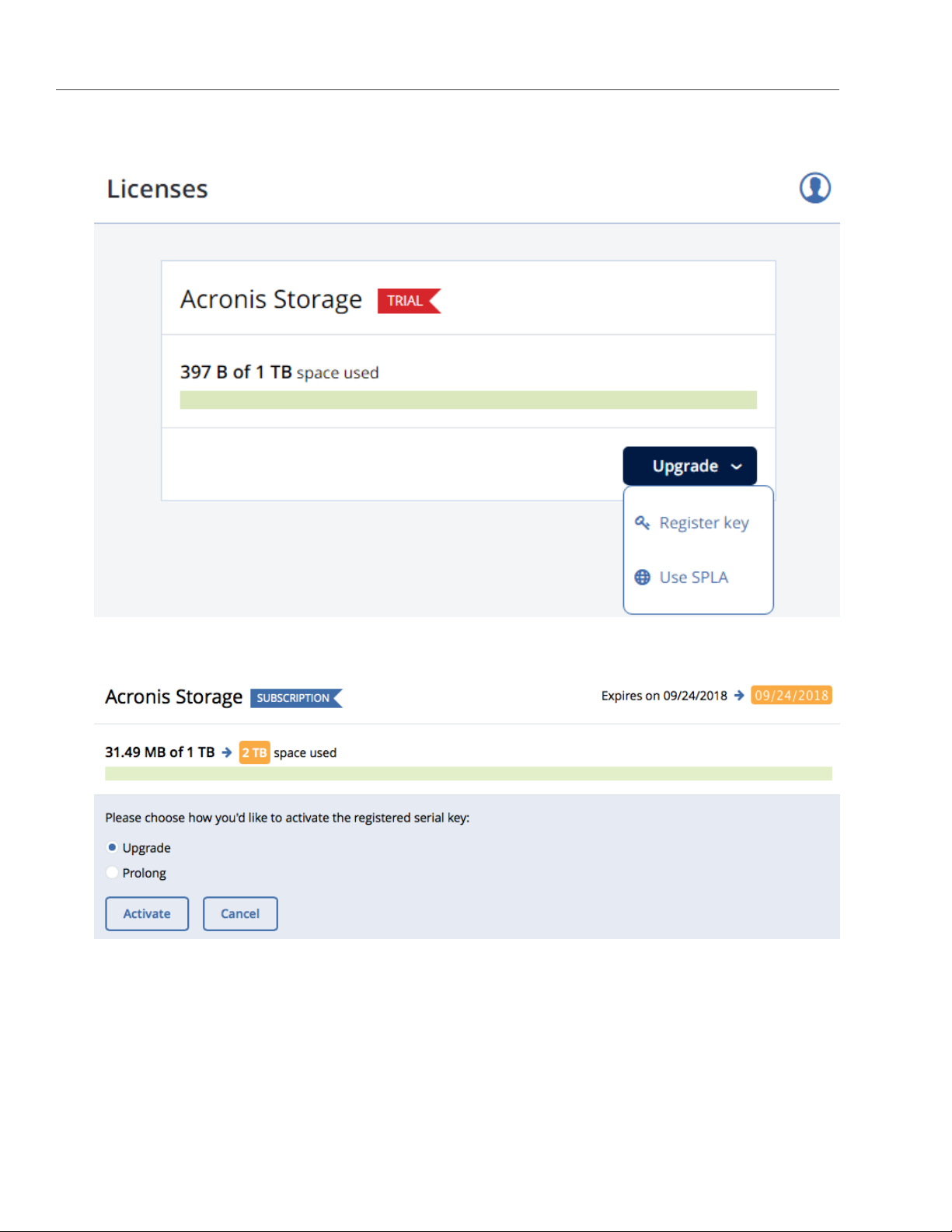
2. On the LICENSES screen, click Upgrade and Register key.
Chapter 2. Managing Acronis Storage
3. Paste the license key, click REGISTER, and choose one of the following:
• Upgrade, to add storage capacity.
• Prolong, to prolong the license.
4. Click Activate.
The expiration date or storage capacity will change according to what the key grants.
38
Page 45

2.12. Managing Licenses
2.12.2 Installing SPLA Licenses
To install a SPLA license, do the following:
1. On the LICENSES screen, click Upgrade and Use SPLA.
2. In the Use SPLA window, select a region from the drop-down list and click Activate. You will be
redirected to a log in page of Acronis Data Cloud.
3. Log in to Acronis Data Cloud.
4. In the Register cluster window, accept the license agreement.
5. In the registration confirmation window, click Done.
The registered cluster will show up in Acronis Data Cloud. You will be able to monitor its resource usage and
download reports.
39
Page 46

Chapter 2. Managing Acronis Storage
2.13 Connecting Remote iSCSI Devices to Storage Cluster Nodes
Acronis Storage allows you to connect remote iSCSI devices to nodes and perceives their LUNs as storage
disks. You can connect iSCSI devices to nodes at any time.
To connect a remote iSCSI device to a node, do the following:
1. On the NODES screen, select a node, open its DISKS tab, and click iSCSI target.
40
Page 47

2.13. Connecting Remote iSCSI Devices to Storage Cluster Nodes
2. In the Remote iSCSI Target window, do the following:
2.1. Specify the IQN of the target.
2.2. In the Portal and Port fields, specify the target’s IP address and port (optional) and click the
corresponding check icon.
2.3. (Optional) If the target has multiple paths, click Add portal and configure it as in the previous step.
2.4. (Optional) If necessary, check CHAP authentication and specify the credentials.
2.5. Click Connect.
Acronis Storage will connect the target (i.e. all its LUNs) and initiate it; corresponding entries with the iSCSI
type will appear in the node’s DISKS list.
To remove the iSCSI target, click iSCSI Target, DELETE CONNECTION, and DELETE.
2.13.1 Assigning Disk Roles To Remote iSCSI Devices
If the node had already been in the cluster before you connected the iSCSI device to it, assign disk roles to all
its LUNs. To do this:
1. Select a disk with the iSCSI type and click Assign.
2. In the Choose role window, select Storage and click Done.
3. Repeat the above steps for every disk with the iSCSI type.
Note: You can assign metadata or cache roles to these disks but it is recommended only for
single-node installations with SAN-provided redundancy that host Acronis Backup Gateways. For more
information on disk roles, see the roles description in Assigning Disk Roles Manually on page 16.
41
Page 48

CHAPTER 3
Monitoring the Storage Cluster
You can monitor the performance of the storage cluster as a whole and its parts.
3.1 Monitoring Storage Cluster Status
The overall cluster statistics are available on the cluster OVERVIEW screen. Pay attention to the cluster status
that can be one of the following:
• HEALTHY. All cluster components are active and operate normally.
• UNKNOWN. Not enough information about the cluster state (e.g., because the cluster is inaccessible).
• DEGRADED. Some of the cluster components are inactive or inaccessible. The cluster is trying to heal
itself, data replication is scheduled or in progress.
• FAILURE. The cluster has too many inactive services, automatic replication is disabled. If the cluster
enters this state, troubleshoot the nodes or contact the support team.
3.2 Monitoring Storage Cluster Space
You can monitor cluster storage space on the cluster OVERVIEW screen. Typical statistics may look like this:
42
Page 49

3.2. Monitoring Storage Cluster Space
The two charts that provide information on how storage space is used are PHYSICAL SPACE and LOGICAL
SPACE. They are described in the following sections in more detail.
3.2.1 Physical Space Chart
The PHYSICAL SPACE chart shows the combined space of all disks available to the cluster. The following
statistics are available:
• Used space. The space occupied by all data chunks and their replicas plus the space occupied by any
other data stored on cluster nodes’ disks.
• Free space. The unused space on all cluster nodes’ disks.
• Total space. The total space on all cluster nodes’ disks.
3.2.2 Logical Space Chart
The LOGICAL SPACE chart represents all the space that can be allocated and used by the cluster for storing
user data. This space includes the following:
• Total space. The maximum disk space available as defined by license.
• Used space. The space occupied exclusively by user data. Replicas and erasure coding metadata are
43
Page 50

Chapter 3. Monitoring the Storage Cluster
not taken into account.
• Free space. The difference between the two above.
3.2.2.1 Understanding Logical Space
When monitoring disk space information in the cluster, keep in mind that logical space is the amount of free
disk space that can be used for storing user data in the form of data chunks and all their replicas. Once this
space runs out, no data can be written to the cluster.
To better understand how logical disk space is calculated, consider the following example:
• The cluster has three disks with the storage role. The first disk has 200 GB of space, the second one has
500 GB, and the third one has 1 TB.
• If the redundancy mode is set to three replicas, each data chunk must be stored as three replicas on
three different disks with the storage role.
In this example, the available logical disk space will be 200 GB, that is, equal to the capacity of the smallest
disk with the storage role. The reason is that each replica must be stored on a different disk. So once the
space on the smallest disk (i.e. 200 GB) runs out, no new chunk replicas can be created unless a new disk
with the storage role is added or the redundancy mode is changed to two replicas.
With the two replicas redundancy mode, the available logical disk space would be 700 GB, because the two
smallest disks combined can hold 700 GB of data.
3.2.3 Monitoring Chunk Status and Replication
You can monitor the state of all chunks in the cluster in the CHUNKS section of the cluster OVERVIEW screen.
The table below lists all possible states a chunk can have.
State Description
healthy Percentage of chunks that have enough active replicas. The normal state of chunks.
offline Percentage of chunks all replicas of which are offline. Such chunks are completely inaccessible
for the cluster and cannot be replicated, read from or written to. All requests to an offline chunk
44
are frozen until a CS that stores that chunk’s replica goes online.
Get offline cluster nodes back online as soon as possible to avoid data loss.
Page 51

3.2. Monitoring Storage Cluster Space
State Description
blocked Percentage of chunks which have fewer active replicas than the set minimal amount. Write re-
quests to a blocked chunk are frozen until it has at least the set minimum amount of replicas.
Read requests to blocked chunks are allowed, however, as they still have some active replicas
left. Blocked chunks have higher replication priority than degraded chunks.
Having blocked chunks in the cluster increases the risk of losing data, so postpone any mainte-
nance on working cluster nodes and get offline chunk servers back online as fast as possible.
degraded Percentage of chunks with the number of active replicas lower than normal but equal to or higher
than the set minimum. Such chunks can be read from and written to.
3.2.4 Monitoring Storage Cluster Services
You can monitor two types of services in the SERVICES section on the cluster OVERVIEW screen:
• MDS, metadata services. Ensure that five are running at all times.
• CS, chunk services. With this chart, you can also keep track of all disks with the storage role.
Typical statistics may look like this:
45
Page 52

Chapter 3. Monitoring the Storage Cluster
If some of the services were not in the healthy state for some time, these time periods will be highlighted in
red on the charts.
3.2.5 Monitoring Storage Cluster I/O Activity
You can monitor the history of the cluster I/O activity on the READ and WRITE charts on the cluster
OVERVIEW screen. Typical statistics may look like this:
46
Page 53

3.3. Monitoring Storage Cluster Objects via SNMP
The current cluster I/O activity averaged for the last 10 seconds is shown as:
• the speed of read and write I/O operations, in megabytes per second (MB/s).
• the number of read and write I/O operations per second (IOPS).
3.3 Monitoring Storage Cluster Objects via SNMP
You can monitor cluster objects via the Simple Network Management Protocol (SNMP). The implementation
conforms to the same Structure of Management Information (SMI) rules as the data in the standard SNMP
context: all objects are organized in a tree; each object identifier (OID) is a series of integers corresponding to
tree nodes and separated by dots.
General information:
• The OID of the root subtree with all the objects you can monitor is 1.3.6.1.4.1.8072.161.1.
• The VSTORAGE-MIB.txt information base file is required to monitor the objects. You can download the
file at http://<management_panel_IP>:8888/api/v2/snmp/mibs/VSTORAGE-MIB.txt.
The following subsections describe ways to enable and use SNMP to monitor cluster objects.
47
Page 54

Chapter 3. Monitoring the Storage Cluster
3.3.1 Enabling SNMP Access
To monitor cluster objects, enable the SNMP access on the node. Do the following in the management panel:
1. On the SETTINGS > Advanced settings > SNMP tab, check Enable SNMP on management node.
Doing so lets your network management system (SNMP monitor) access the cluster via the SNMP
protocol on the management node’s port 161.
2. Click the corresponding link to download the MIB file and set it up in your SNMP monitor.
3. If required, have Acronis Storage send SNMP traps to your SNMP monitor. Do the following:
3.1. Check Send SNMP traps to Network Management System.
48
Page 55

3.3. Monitoring Storage Cluster Objects via SNMP
3.2. Specify the IP of the system, and, if required, change the default Port and Community.
3.3. If required, click SEND TEST TRAP to test the service.
4. Click SAVE to apply changes.
3.3.2 Accessing Storage Cluster Information Objects via SNMP
You can access storage cluster information objects with SNMP tools of your choice, e.g., the free Net-SNMP
suite for Linux.
To obtain storage cluster information on a node with the management panel, place the MIB file to
/usr/share/snmp/mibs and run the snmpwalk command. For example:
# snmpwalk -M /usr/share/snmp/mibs -m VSTORAGE-MIB -v 2c -c public \
localhost:161 VSTORAGE-MIB:cluster
Typical output may be the following:
VSTORAGE-MIB::clusterName.0 = STRING: "cluster1"
VSTORAGE-MIB::healthStatus.0 = STRING: "healthy"
VSTORAGE-MIB::usedSpace.0 = Counter64: 173732322
VSTORAGE-MIB::totalSpace.0 = Counter64: 1337665179648
VSTORAGE-MIB::freeSpace.0 = Counter64: 1318963253248
VSTORAGE-MIB::licenseStatus.0 = STRING: "unknown"
VSTORAGE-MIB::licenseCapacity.0 = Counter64: 1099511627776
VSTORAGE-MIB::licenseExpirationStatus.0 = STRING: "None"
VSTORAGE-MIB::ioReadOpS.0 = Counter64: 0
VSTORAGE-MIB::ioWriteOpS.0 = Counter64: 0
VSTORAGE-MIB::ioReads.0 = Counter64: 0
VSTORAGE-MIB::ioWrites.0 = Counter64: 0
VSTORAGE-MIB::csActive.0 = Counter64: 11
VSTORAGE-MIB::csTotal.0 = Counter64: 11
VSTORAGE-MIB::mdsAvail.0 = Counter64: 4
VSTORAGE-MIB::mdsTotal.0 = Counter64: 4
<...>
3.3.2.1 Listening to SNMP Traps
To start listening to SNMP traps, do the following:
1. Configure the snmptrapd daemon to log SNMP traps, allow them to trigger executable actions, and
resend data to the network. To do this, add the following public community string to the
/etc/snmp/snmptrapd.conf file:
49
Page 56

Chapter 3. Monitoring the Storage Cluster
authCommunity log,execute,net public
2. Start the daemon and specify the MIB file:
# snmptrapd -M /usr/share/snmp/mibs -m VSTORAGE-MIB -n -f -Lf /tmp/traps.log
3. Send a test trap from the
4. View the log file:
# tail -f /tmp/traps.log
2017-04-23 02:48:18 UDP: [127.0.0.1]:58266->[127.0.0.1]:162 [UDP: \
[127.0.0.1]:58266->[127.0.0.1]:162]:
SNMPv2-SMI::mib-2.1.3.0 = Timeticks: (1687405) 4:41:14.05 \
SNMPv2-SMI::snmpModules.1.1.4.1.0 = OID: VSTORAGE-MIB::generalAlert \
VSTORAGE-MIB::trapType = STRING: Test Case VSTORAGE-MIB::trapMsg = \
STRING: This Is Text Message to end-user \
VSTORAGE-MIB::trapPriority = Counter64: 1
The test trap is considered a generalAlert.
SETTINGS>Advanced settings>SNMP
tab in the management panel.
3.3.3 Monitoring the Storage Cluster with Zabbix
To configure cluster monitoring in Zabbix, do the following:
1. On the SETTINGS > Advanced settings > SNMP tab, click the corresponding link to download a
template for Zabbix.
Note: The template is compatible with Zabbix 3.x.
2. In Zabbix, click Configuration > Templates > Import and Browse.
50
Page 57

3.3. Monitoring Storage Cluster Objects via SNMP
3. Navigate to the template, select it, and click Import.
4. Click Configuration > Hosts > Create host.
51
Page 58

Chapter 3. Monitoring the Storage Cluster
5. On the Host tab, do the following:
5.1. Specify the Host name of the management node and its Visible name in Zabbix.
5.2. Specify vstorage in the New group field.
5.3. Remove the Agent Interfaces section.
5.4. Add an SNMP interfaces section and specify the IP of the management node in the corresponding
field.
6. On the Templates tab, click Select next to the Link new templates field.
52
Page 59

3.3. Monitoring Storage Cluster Objects via SNMP
7. In the Zabbix Server: Templates window, check the Template VStorageSNMP template and click Select.
8. Back on the Templates tab, click the Add link in the Link new templates section. The VStorageSNMP
template will appear in the Linked templates group.
9. Having configured the host and added its template, click the Add button.
53
Page 60

Chapter 3. Monitoring the Storage Cluster
In a few minutes, the cluster’s SNMP label in the Availability column on the Configuration > Hosts screen will
turn green.
To monitor cluster’s parameters, open the Monitoring > Latest data screen, set the filter’s Host groups to
vstorage and click Apply.
You can create performance charts on the Configuration > Hosts > <cluster> > Graphs tab and a workplace
for them on the Monitoring > Screens tab.
3.3.4 Storage Cluster Objects and Traps
The table below describes cluster-related objects you can monitor:
Object Description
VSTORAGE-MIB:cluster General cluster information.
VSTORAGE-MIB:csStatTable Chunk server statistics table.
VSTORAGE-MIB:mdsStatTable Metadata server statistics table.
VSTORAGE-MIB::clusterName Cluster name.
VSTORAGE-MIB::healthStatus Cluster health status.
VSTORAGE-MIB::usedSpace The space occupied by all data chunks and their replicas plus the space
occupied by any other data stored on cluster nodes’ disks.
VSTORAGE-MIB::totalSpace The total space on all cluster nodes’ disks.
VSTORAGE-MIB::freeSpace The unused space on all cluster nodes’ disks.
VSTORAGE-MIB::licenseStatus License status.
VSTORAGE-MIB::licenseCapacity The maximum disk space available as defined by license.
54
Page 61

3.3. Monitoring Storage Cluster Objects via SNMP
Object Description
VSTORAGE-
MIB::licenseExpirationStatus
VSTORAGE-MIB::ioReadOpS Current read speed in operations per second.
VSTORAGE-MIB::ioWriteOpS Current write speed in operations per second.
VSTORAGE-MIB::ioReads Current read speed in bytes per second.
VSTORAGE-MIB::ioWrites Current read write in bytes per second.
VSTORAGE-MIB::csActive The number of active chunk servers.
VSTORAGE-MIB::csTotal The total number of chunk servers.
VSTORAGE-MIB::mdsAvail The number of running metadata servers.
VSTORAGE-MIB::mdsTotal The total number of metadata servers.
VSTORAGE-MIB::s3OsAvail The number of running S3 object servers.
VSTORAGE-MIB::s3OsTotal The total number of S3 object servers.
VSTORAGE-MIB::s3NsAvail The number of running S3 name servers.
VSTORAGE-MIB::s3NsTotal The total number of S3 name servers.
VSTORAGE-MIB::s3GwAvail The number of running S3 gateways.
VSTORAGE-MIB::s3GwTotal The total number of S3 gateways.
License expiration status.
The table below describes the CS-related objects you can monitor:
Object Description
VSTORAGE-MIB::csId Chunk server identifier.
VSTORAGE-MIB::csStatus Current chunk server status.
VSTORAGE-MIB::csIoReadOpS Current read speed of a chunk server in operations per second.
VSTORAGE-MIB::csIoWriteOpS Current write speed of a chunk server in operations per second.
VSTORAGE-MIB::csIoWait The percentage of time spent waiting for I/O operations. Includes time
spent waiting for synchronization.
VSTORAGE-MIB::csIoReadS Current read speed of a chunk server in bytes per second.
VSTORAGE-MIB::csIoWriteS Current write speed of a chunk server in bytes per second.
The table below describes MDS-related objects you can monitor:
Object Description
VSTORAGE-MIB::mdsId Metadata server identifier.
VSTORAGE-MIB::mdsStatus Current metadata server status.
55
Page 62

Chapter 3. Monitoring the Storage Cluster
Object Description
VSTORAGE-MIB::mdsMemUsage The amount of memory used by a metadata server.
VSTORAGE-MIB::mdsCpuUsage The percentage of the CPU’s capacity used by a metadata server.
VSTORAGE-MIB::mdsUpTime Time since the startup of a metadata server.
The table below describes SNMP traps triggered by the specified alerts:
Trap Alert
licenseExpired The license has expired.
tooFewClusterFreeLogicalSpace Too few free space is left.
tooFewClusterFreePhysicalSpace Too few physical space is left.
tooFewNodes Too few nodes are left.
tooFewMdses Too few MDSs are left.
generalAlert Other.
56
Page 63

CHAPTER 4
Monitoring Storage Cluster Nodes
Nodes added to the Acronis Storage infrastructure are listed on the NODES screen, grouped by status. If the
storage cluster has not been created yet, you will only see nodes in the UNASSIGNED list. If the storage
cluster exists, its nodes will be listed on the screen.
4.1 Storage Cluster Node Statuses
A storage cluster node can have one of the following statuses:
• HEALTHY. All the storage services on the node are running.
• OFFLINE. The node cannot be reached from the management panel, although it may still be up and its
services may be running.
• FAILED. One or more storage services on the node have failed.
• UNASSIGNED. The node is not assigned to a cluster.
57
Page 64

Chapter 4. Monitoring Storage Cluster Nodes
4.2 Monitoring Storage Cluster Node Performance
To monitor the performance of a storage cluster node, open the NODES screen and click a node. On the
node overview screen, you will see performance statistics described below.
The overall statistics include:
• the number of CPUs and the amount of RAM,
• CPU usage, in percent over time,
• RAM usage, in percent over time.
The DISKS section shows:
• the number of HDD and SSD drives and their statuses,
• node I/O activity over time on the read and write charts.
The NETWORK section shows:
• the list of network interfaces and their statuses,
58
Page 65

4.2. Monitoring Storage Cluster Node Performance
• the amount of transmitted (TX) and received (RX) traffic over time.
The following sections provide more information on disk and network usage.
4.2.1 Monitoring Storage Cluster Node Disks
To monitor the usage and status of node disks, click the DISKS link on the node overview screen. You will see
a list of all disks on the node and their status icons.
A disk status icon shows the combined status of S.M.A.R.T. and the service corresponding to the disk role. It
can be one of the following:
• OK. The disk and service are healthy.
• Failed. The service has failed or S.M.A.R.T. reported an error.
• Releasing. The service is being released. When the process finishes, the disk status will change to Ok.
On this screen, you can:
• monitor the details and performance of each disk,
• manage disk roles,
• have the disk blink its activity LED. Works only for LSI and PERC controllers.
To monitor performance of a particular disk, select it and click Performance. The Drive performance panel
will display the I/O activity of the disk.
To view information about the disk, including its S.M.A.R.T. status, click Details.
To have the disk blink its activity LED, select the disk, and click Blink. To have the disk stop blinking, click
Unblink.
59
Page 66

Chapter 4. Monitoring Storage Cluster Nodes
4.2.1.1 Monitoring the S.M.A.R.T. Status of Node Disks
The S.M.A.R.T. status of all disks is monitored by a tool installed along with Acronis Storage. Run every 10
minutes, the tool polls all disks attached to nodes, including journaling SSDs and system disks, and reports
the results to the management node.
Note: For the tool to work, make sure the S.M.A.R.T. functionality is enabled in node’s BIOS.
If a S.M.A.R.T. warning message is shown in the node status, one of that node’s disks is in pre-failure
condition and should be replaced. If you continue using the disk, keep in mind that it may fail or cause
performance issues.
Pre-failure condition means that at least one of these S.M.A.R.T. counters is not zero:
• Reallocated Sector Count
• Reallocated Event Count
• Current Pending Sector Count
• Offline Uncorrectable
4.3 Monitoring Node Network
To monitor the node’s network usage, click NETWORK on the node overview screen.
To display the performance charts of a specific network interface, select it in the list and click Performance.
When monitoring network performance, keep in mind that if the TX DROPS and/or RX DROPS charts are not
empty, the network is experiencing issues and requires attention.
To display the details of a network interface, click Details. The Network details panel shows the interface
state, bandwidth, MTU, MAC address, and all IP addresses.
60
Page 67

CHAPTER 5
Viewing Alerts and Audit Log
and Sending E-mail
Notifications
This chapter describes Acronis Storage alerts, audit log, and e-mail notifications settings.
5.1 Viewing Alerts
The ALERTS tab lists all the alerts logged by Acronis Storage. An alert is generated and logged each time one
of the following conditions is met or events happen:
• a critical issue has happened with a cluster, its components (CS, MDS), disks, nodes, or services;
• cluster requires configuration or more resources to build or restore its health;
• network requires configuration or is experiencing issues that may affect performance;
• license is about to expire or has expired;
• cluster is about to or has run out of available space.
61
Page 68

Chapter 5. Viewing Alerts and Audit Log and Sending E-mail Notifications
To view an alert details, select an alert on the ALERTS tab and click Details.
Alerts can be ignored (deleted from the alerts list) or postponed for several hours. Postponed alerts
reappear in the list after some time.
To ignore or postpone an alert, select it and click the corresponding button.
5.2 Viewing Audit Log
The AUDIT LOG tab lists all management operations performed by users and their activity events.
62
Page 69

5.3. Sending E-mail Notifications
To view detailed information on a log entry, select it and click Show extended details.
5.3 Sending E-mail Notifications
Acronis Storage can send automatic e-mail notifications about errors, warnings, and alerts.
To set up e-mail notifications, do the following:
1. On the SETTINGS > Advanced settings > EMAIL NOTIFICATIONS tab, specify the following information:
63
Page 70

Chapter 5. Viewing Alerts and Audit Log and Sending E-mail Notifications
1.1. In the From and Sender name fields, the notification sender’s e-mail and name.
1.2. In the To field, one or more notification recipient e-mails, one per line.
1.3. In the User account fields, the credentials of the notification sender registered on the SMTP server.
1.4. In the Outgoing SMTP server field, the DNS name of the SMTP server, either public (e.g.,
smtp.gmail.com) or the one in your organization.
Note: The management node must be able to access the SMTP server.
1.5. If required, a custom
1.6. In the Security field, the security protocol of the SMTP server.
SMTP port
the server uses.
64
Page 71

5.3. Sending E-mail Notifications
2. Tick the checkboxes for alerts you want to get notified about.
3. Click SAVE.
To send a test e-mail, specify your e-mail registered on the SMTP server in both the From and To fields and
click TEST.
65
Page 72

CHAPTER 6
Exporting Storage Cluster Data
Acronis Storage allows you to export storage space as:
• Block storage via iSCSI for virtualization, databases and other needs.
• Object storage for storing unlimited number of files via an Amazon S3 compatible protocol. You can
store data like media files, backups, Open Xchange files and access the storage using Dropbox-like
applications. You can build your own Amazon S3 compatible object storage services as a part of your
cloud offering or for internal needs.
• A back-end for Acronis Backup Cloud and Acronis Backup Advanced backups.
• NFS exports.
6.1 Exporting Data via iSCSI
Acronis Storage allows you to export cluster disk space to external operating systems and third-party
virtualization solutions in the form of LUN block devices over iSCSI in a SAN-like manner.
In Acronis Storage, you can create and run multiple iSCSI targets per cluster node. In turn, each iSCSI target
can have multiple LUNs (virtual disks). At any given moment, each iSCSI target runs on a single node. If a
node fails, iSCSI targets hosted on it are moved to and re-launched on a healthy node.
The figure below shows a typical setup for exporting Acronis Storage disk space over iSCSI.
66
Page 73

6.1. Exporting Data via iSCSI
In this example, two Acronis Storage nodes host one iSCSI target each, while the third hosts two iSCSI targets.
Each node connects to two networks: internal for storage cluster communication and external (in relation to
the storage cluster) for iSCSI exporting. Each iSCSI target has a unique static IP address from a dedicated
subnet of the datacenter network.
6.1.1 Creating iSCSI Targets
Note:
1. Each iSCSI target must be assigned at least one unique IP address from DC network’s static pool.
2. The name of each iSCSI target must be unique in the Acronis Storage cluster.
3. Acronis Storage iSCSI targets support persistent reservations to allow iSCSI initiators obtain
exclusive access to the specified target’s LUNs.
To create a target, do the following:
1. On the SERVICES > iSCSI > Targets screen, click ADD TARGET.
67
Page 74

Chapter 6. Exporting Storage Cluster Data
2. On the Add target panel, type a name for the new target in the Name field.
3. In the node drop-down list, select a node on which the target will be located. The node should have an
iSCSI role assigned to one of its network interfaces to appear in the list.
4. If necessary, check the Enable CHAP box and select an iSCSI user in the corresponding drop-down list
(For more information on CHAP users, see Managing iSCSI Users on page 73).
68
Page 75

6.1. Exporting Data via iSCSI
5. Click Add to specify one or more IP addresses for the target.
6. If necessary, enable and specify IOPS and bandwidth limits for the target. If both limits are set, the first
one that is hit is applied. Setting a limit value to zero disables the limit.
7. Click Done to create the target.
The ISCSI target will be automatically started after creation and the initiators will be able to access the target
via the specified IP address.
6.1.1.1 Performance Tips
• Spread iSCSI targets evenly across nodes in the cluster. For example, ten nodes with one iSCSI target
per each will perform better than a single node with ten iSCSI targets on it.
• Fewer LUNs per more iSCSI targets will perform better than more LUNs per fewer iSCSI targets.
6.1.2 Listing, Stopping, and Deleting iSCSI Targets
On the iSCSI targets screen, you can list and manage all iSCSI targets and their LUNs, and display detailed
information about specific iSCSI targets registered on a node.
To stop or delete an iSCSI target, select it on the iSCSI targets screen and click Stop or Delete, respectively.
Doing so will disconnect the iSCSI initiator from the target. However, breaking the connection in such a way
may result in I/O errors on the iSCSI initiator’s side.
6.1.3 Configuring iSCSI Targets
To configure an iSCSI target, do the following:
1. On the SERVICES > iSCSI > Targets screen, select the necessary target and click Configure.
2. On the Configure target screen, specify the necessary parameters.
69
Page 76

Chapter 6. Exporting Storage Cluster Data
3. Click Done.
70
Page 77

6.1. Exporting Data via iSCSI
6.1.3.1 Listing LUNs
Each iSCSI target can have multiple LUNs (virtual disks or volumes). You can list the LUNs of a target and
iSCSI initiators that are currently connected.
To list the LUNs, open the SERVICES > iSCSI > Targets screen, select a target and click a link in the LUNs
column.
To list the initiators that are currently connected to iSCSI targets, open the INITIATORS tab on the same
screen.
6.1.3.2 Adding LUNs
To add a LUN to an iSCSI target, do the following:
1. On the SERVICES > iSCSI > Targets screen, select the necessary target and click a link in the LUNs
column.
2. To add a new LUN to the list, click ADD LUN.
71
Page 78

Chapter 6. Exporting Storage Cluster Data
3. On the Add LUN screen, select the LUN’s number from the drop-down list.
4. In the LUN Size field, specify the size of the LUN in GB; select a tier from the drop-down list to the right.
For more information on tiers, see the Installation Guide.
5. From the Failure domain drop-down list, choose a placement policy for replicas. For more details, see
the Installation Guide.
72
Page 79

6.1. Exporting Data via iSCSI
6. Choose a data redundancy mode. For more details, see the Installation Guide.
7. Click Done.
6.1.3.3 Configuring LUNs
To configure a LUN of an iSCSI target, do the following:
1. On the SERVICES > iSCSI > Targets screen, stop the target to which the LUN belongs.
2. Click a link in the target’s LUNs column.
3. On the Configure LUN screen, specify the LUN size in the corresponding field.
4. Click Done.
6.1.3.4 Deleting LUNs
To delete a LUN, do the following:
1. On the
column.
2. Select the necessary LUN in the list and click Delete.
SERVICES>iSCSI>Targets
screen, select the necessary target and click a link in the
6.1.4 Managing iSCSI Users
You can restrict access to iSCSI targets by means of CHAP authentication.
To make use of CHAP authentication, you need to:
1. Create a CHAP account.
2. Create an iSCSI target bound to this CHAP account.
These actions are described in detail in the following subsections.
LUNs
6.1.4.1 Creating CHAP Accounts for iSCSI Targets
To create a CHAP account, do the following:
1. On the SERVICES > iSCSI Users screen, click Add user.
73
Page 80

Chapter 6. Exporting Storage Cluster Data
2. Specify login, password, and, if necessary, a description for the account. The password should be 12 to
16 characters long for Windows clients to be able to establish connections.
3. Click Done.
The newly created CHAP user account will be listed on the iSCSI Users screen.
6.1.4.2 Creating iSCSI Targets Bound to CHAP Accounts
To create an iSCSI target bound to a CHAP account, do the following:
1. On the SERVICES > iSCSI > Targets screen, select an iSCSI target and click Configure.
2. On the Configure target screen, check Enable CHAP and/or Enable mutual CHAP and select users in
the corresponding drop-down lists. If you enable CHAP, the target will authenticate the initiator. If you
enable mutual CHAP, the initiator will authenticate the target. These options can be enabled in any
combination.
74
Page 81

6.1. Exporting Data via iSCSI
3. Click Done.
6.1.4.3 Changing CHAP Account Passwords
To change the password of a CHAP account, do the following:
1. On the SERVICES > iSCSI Users screen, select a user and click Configure.
2. In the Password section on the Configure user screen, click change.
75
Page 82

Chapter 6. Exporting Storage Cluster Data
3. Type a new password in the corresponding field and click Done. The password should be 12 to 16
characters long for Windows clients to be able to establish connection.
The new password will become active after target reboot.
6.2 Exporting Data via S3
Acronis Storage allows you to export cluster disk space to customers in the form of an S3-like object-based
storage.
Acronis Storage is implemented as an Amazon S3-like API, which is one of the most common object storage
APIs. End users can work with Acronis Storage as they work with Amazon S3. You can use the usual
applications for S3 and continue working with it after the data migration from Amazon S3 to Acronis Storage.
Object storage is a storage architecture that enables managing data as objects (like in a key-value storage) as
opposed to files in file systems or blocks in a block storage. Except for the data, each object has metadata
76
Page 83

6.2. Exporting Data via S3
that describes it as well as a unique identifier that allows finding the object in the storage. Object storage is
optimized for storing billions of objects, in particular for application storage, static web content hosting,
online storage services, big data, and backups. All of these uses are enabled by object storage thanks to a
combination of very high scalability and data availability and consistency.
Compared to other types of storage, the key difference of object storage is that parts of an object cannot be
modified, so if the object changes a new version of it is spawned instead. This approach is extremely
important for maintaining data availability and consistency. First of all, changing an object as a whole
eliminates the issue of conflicts. That is, the object with the latest timestamp is considered to be the current
version and that is it. As a result, objects are always consistent, i.e. their state is relevant and appropriate.
Another feature of object storage is eventual consistency. Eventual consistency does not guarantee that
reads are to return the new state after the write has been completed. Readers can observe the old state for
an undefined period of time until the write is propagated to all the replicas (copies). This is very important for
storage availability as geographically distant data centers may not be able to perform data update
synchronously (e.g., due to network issues) and the update itself may also be slow as awaiting acknowledges
from all the data replicas over long distances can take hundreds of milliseconds. So eventual consistency
helps hide communication latencies on writes at the cost of the probable old state observed by readers.
However, many use cases can easily tolerate it.
6.2.1 S3 Storage Infrastructure Overview
The object storage infrastructure consists of the following entities: object servers (OS), name servers (NS), S3
gateways (GW), and the block-level backend.
These entities run as services on the Acronis Storage nodes. Each service should be deployed on multiple
Acronis Storage nodes for high availability.
77
Page 84

Chapter 6. Exporting Storage Cluster Data
• An object server stores actual object data received from S3 gateway. The data is packed into special
containers to achieve high performance. The containers are redundant, you can specify the
redundancy mode while configuring object storage. An object server also stores its own data in block
storage with built-in high availability.
• A name server stores object metadata received from S3 gateway. Metadata includes object name, size,
ACL (access control list), location, owner, and such. Name server (NS) also stores its own data in block
storage with built-in high availability.
• An S3 gateway is a data proxy between object storage services and end users. It receives and handles
Amazon S3 protocol requests and S3 user authentication and ACL checks. The S3 gateway uses the
NGINX web server for external connections and has no data of its own (i.e. is stateless).
• The block-level backend is block storage with high availability of services and data. Since all object
storage services run on hosts, no virtual environments (and hence licenses) are required for object
storage.
78
Page 85

6.2. Exporting Data via S3
6.2.2 Planning the S3 Cluster
Before creating an S3 cluster, do the following:
1. Define which nodes of the Acronis Storage cluster will run the S3 storage access point services. It is
recommended to have all nodes available in Acronis Storage run these services.
2. Configure the network so that the following is achieved:
• All components of the S3 cluster communicate with each other via the S3 private network. All
nodes of an S3 cluster must be connected to the S3 private network. Acronis Storage internal
network can be used for this purpose.
• The nodes running S3 gateways must have access to the public network.
• The public network for the S3 gateways must be balanced by an external DNS load balancer.
For more details on network configuration, refer to the Installation Guide.
3. All components of the S3 cluster should run on multiple nodes for high-availability. Name server and
object server components in the S3 cluster are automatically balanced and migrated between S3 nodes.
S3 gateways are not automatically migrated; their high availability is based on DNS records. You should
maintain the DNS records manually when adding or removing the S3 gateways.
6.2.3 Sample S3 Storage
This section shows a sample object storage deployed on top of a storage cluster of five nodes that run
various services. The final setup is shown on the figure below.
79
Page 86

Chapter 6. Exporting Storage Cluster Data
80
Page 87

6.2. Exporting Data via S3
6.2.4 Creating the S3 Cluster
To set up object storage services on a cluster node, do the following:
1. Make sure that S3 private network is configured on each node that will run object storage services.
2. On the SERVICES > Nodes screen, check the box of each cluster node where object storage services will
run.
3. Click Create S3 cluster.
4. Make sure a network interface with an Objest Storage private role is selected in the drop-down list.
The corresponding interfaces with S3 public roles will be selected automatically.
Note: If necessary, click the cogwheel icon and, on the Network Configuration screen,
configure S3 roles.
5. Click Proceed.
6. In Tier, select the storage tier that will be used for the object storage. For information about storage
tiers, consult the Installation Guide.
81
Page 88

Chapter 6. Exporting Storage Cluster Data
7. In Failure domain, choose a placement policy for replicas. For more details, see the Installation Guide.
8. In Data redundancy, select the redundancy mode that the object storage will use. For more details,
see the Installation Guide.
Note: You can later change the redundancy mode on the S3 > Settings panel.
9. Click Proceed.
10. Specify the external (publicly resolvable) DNS name for the S3 endpoint that will be used by the end
82
Page 89

6.2. Exporting Data via S3
users to access the object storage. For example, mys3storage.example.com. Click Proceed.
Important: Configure your DNS server according to the example suggested in the management
panel.
11. From the drop-down list, select an S3 endpoint protocol: HTTP, HTTPS or both.
Note: It is recommended to use only HTTPS for production deployments.
If you have selected HTTPS, do one of the following:
• Check Generate self-signed certificate to get a self-signed certificate for HTTPS evaluation
purposes.
83
Page 90

Chapter 6. Exporting Storage Cluster Data
Note:
1. S3 geo-replication requires a certificate from a trusted authority. It does not work with
self-signed certificates.
2. To access the data in the S3 cluster via a browser, add the self-signed certificate to
browser’s exceptions.
• Acquire a key and a trusted wildcard SSL certificate for endpoint’s bottom-level domain. For
example, the endpoint s3.storage.example.com would need a wildcard certificate for
*.s3.storage.example.com with the subject alternative name s3.storage.example.com.
Upload the certificate, and, depending on the certificate type, do one of the following:
•
in case the certificate is contained in a PKCS#12 file, specify the passphrase;
•
upload the SSL key.
12. If required, click Configure Acronis Notary and specify Notary DNS name and Notary user key. For
more information on Acronis Notary, see Managing Acronis Notary in S3 Buckets.
13. Click Done to create an S3 cluster.
After the cluster is created, on the S3 Overview screen, you can view cluster status, hostname, used disk
capacity, the number of users, I/O activity, and the state of S3 services.
84
Page 91

6.2. Exporting Data via S3
To check if the S3 cluster is successfully deployed and can be accessed by users, visit https://<S3_DNS_name>
or http://<S3_DNS_name> in your browser. You should receive the following XML response:
<Error>
<Code>AccessDenied</Code>
<Message/>
</Error>
To start using the S3 storage, you will also need to create at least one S3 user.
6.2.5 Managing S3 Users
The concept of S3 user is one of the base concepts of object storage along with those of object and bucket
(container for storing objects). The Amazon S3 protocol uses a permission model based on access control
lists (ACLs) where each bucket and each object is assigned an ACL that lists all users with access to the given
resource and the type of this access (read, write, read ACL, write ACL). The list of users includes the entity
85
Page 92

Chapter 6. Exporting Storage Cluster Data
owner assigned to every object and bucket at creation. The entity owner has extra rights compared to other
users. For example, the bucket owner is the only one who can delete that bucket.
User model and access policies implemented in Acronis Storage comply with the Amazon S3 user model and
access policies.
User management scenarios in Acronis Storage are largely based on the Amazon Web Services user
management and include the following operations: create, query, and delete users as well as generate and
revoke user access key pairs.
6.2.5.1 Adding S3 Users
To add an S3 user, do the following:
1. On the SERVICES > S3 Users screen, click Add user.
2. Specify a valid email address as login for the user and click Done.
86
Page 93

6.2. Exporting Data via S3
6.2.5.2 Managing S3 Access Key Pairs
Each S3 user has one or two key pairs (access key and secret key) for accessing the S3 cloud. You can think of
the access key as login and the secret key as password. (For more information about S3 key pairs, refer to
the Amazon documentation.) The access keys are generated and stored locally in the Acronis Storage cluster
on S3 name servers. Each user can have up to two key pairs. It is recommended to periodically revoke old
and generate new access key pairs.
To view, add, or revoke the S3 access key pairs for an S3 user, do the following:
1. Select a user in the list and click Keys.
87
Page 94

Chapter 6. Exporting Storage Cluster Data
2. The existing keys will be shown on the Keys panel.
• To revoke a key, click Revoke.
• To add a new key, click Generate access key.
To access a bucket, a user will need the following information:
• management panel IP address,
• DNS name of the S3 cluster specified during configuration,
• S3 access key ID,
• S3 secret access key,
• SSL certificate if the HTTPS protocol was chosen during configuration.
Note: The certificate file can be found in the /etc/nginx/ssl/ directory on any node hosting the
S3 gateway service.
To automatically log in to S3 with user credentials using the generated keys, select a user and click Browse.
88
Page 95

6.2. Exporting Data via S3
Note: To Browse using an SSL certificate, make sure it is valid or, in case of a self-signed one, add it to
browser’s exceptions.
6.2.6 Managing S3 Buckets
All objects in Amazon S3-like storage are stored in containers called “buckets”. Buckets are addressed by
names that are unique in the given object storage, so an S3 user of that object storage cannot create a
bucket that has the same name as a different bucket in the same object storage. Buckets are used to:
• group and isolate objects from those in other buckets,
• provide ACL management mechanisms for objects in them,
• set per-bucket access policies, for example, versioning in the bucket.
In the current version of Acronis Storage, you can enable and disable Acronis Notary for object storage
buckets and monitor the space used by them on the SERVICES > S3 > Buckets screen. You cannot create and
manage object storage buckets from Acronis Storage management panel. However, you can do it via the
Acronis Storage user panel or by using a third-party application. For example, the applications listed below
allow you to perform the following actions:
• CyberDuck: create and manage buckets and their contents.
• MountainDuck: mount object storage as a disk drive and manage buckets and their contents.
• Backup Exec: store backups in the object storage.
6.2.6.1 Listing S3 Bucket Contents
You can list bucket contents with a web browser. To do this, visit the URL that consists of the external DNS
name for the S3 endpoint that you specified when creating the S3 cluster and the bucket name. For example,
mys3storage.example.com/mybucket or mybucket.mys3storage.example.com (depending on DNS configuration).
Note: You can also copy the link to bucket contents by right-clicking it in CyberDuck, and then
selecting Copy URL.
89
Page 96

Chapter 6. Exporting Storage Cluster Data
6.2.6.2 Managing Acronis Notary in S3 Buckets
Acronis Storage offers integration with the Acronis Notary service to leverage blockchain notarization and
ensure the immutability of data saved in object storage clusters. To use Acronis Notary in user buckets, you
need to set it up in the S3 cluster and enable it for said buckets.
Setting Up Acronis Notary
To set up Acronis Notary, do the following:
1. Get the DNS name and the user key for the notary service from your sales contact.
2. On the SERVICES > S3 screen, click Notary settings.
3. On the Notary Settings screen, specify the DNS name and user key in the respective fields and click
Done.
90
Page 97

6.2. Exporting Data via S3
Enabling and Disabling Acronis Notary
To enable or disable blockchain notarization for a bucket, select a bucket on the SERVICES > S3 > Buckets
screen and click Enable Notary or Disable Notary, respectively.
Notarization is disabled for new buckets by default.
Note: Once you enable notarization for a bucket, certificates are created automatically only for the
newly uploaded files. The previously uploaded files are left unnotarized. Once a file was notarized, it will
remain notarized even if you disable notarization later.
6.2.7 Best Practices for Using S3 in Acronis Storage
This section offers recommendations on how to best use the S3 feature of Acronis Storage.
6.2.7.1 S3 Bucket and Key Naming Policies
It is recommended to use bucket names that comply with DNS naming conventions:
• can be from 3 to 63 characters long,
• must start and end with a lowercase letter or number,
• can contain lowercase letters, numbers, periods (.), hyphens (-), and underscores (_),
91
Page 98

Chapter 6. Exporting Storage Cluster Data
• can be a series of valid name parts (described previously) separated by periods.
An object key can be a string of any UTF-8 encoded characters up to 1024 bytes long.
6.2.7.2 Improving Performance of PUT Operations
Object storage supports uploading objects as large as 5 GB per single PUT request (5 TB via multipart
upload). Upload performance can be improved by splitting large objects into pieces and uploading them
concurrently (thus dividing the load between multiple OS services) with multipart upload API.
It is recommended to use multipart uploads for objects larger than 5 MB.
6.2.8 Replicating S3 Data Between Datacenters
Acronis Storage can store replicas of S3 cluster data and keep them up-to-date in multiple geographically
distributed datacenters with S3 clusters based on Acronis Storage. Geo-replication reduces the response
time for local S3 users accessing the data in a remote S3 cluster or remote S3 users accessing the data in a
local S3 cluster as they do not need to have an Internet connection.
Geo-replication schedules the update of the replicas as soon as any data is modified. Geo-replication
performance depends on the speed of Internet connection, the redundancy mode, and cluster performance.
If you have multiple datacenters with enough free space, it is recommended to set up geo-replication
between S3 clusters residing in these datacenters.
Important: Each cluster must have its own SSL certificate signed by a global certificate authority.
To set up geo-replication between S3 clusters, exchange tokens between datacenters as follows:
1. In the management panel of a remote datacenter, open the SERVICES > S3 > GEO-REPLICATION screen.
92
Page 99

6.2. Exporting Data via S3
2. In the section of the home S3 cluster, click TOKEN and, on the Get token panel, copy the token.
3. In the management panel of the local datacenter, open the SERVICES > S3 > GEO-REPLICATION screen
and click ADD DATACENTER.
93
Page 100

Chapter 6. Exporting Storage Cluster Data
4. Enter the copied token and click Done.
5. Configure the remote Acronis Storage S3 cluster the same way.
6.2.9 Monitoring S3 Access Points
The S3 monitoring screen enables you to inspect the availability of each S3 component as well as the
performance of NS and OS services (which are highly available).
If you see that some of the NS or OS services are offline, it means that the S3 access point does not function
properly, and you should contact support consult the CLI guide for low-level troubleshooting. S3 gateways
are not highly available, but DNS load balancing should be enough to avoid downtime if the gateway fails.
The performance charts represent the number of operations that the OS/NS services are performing.
6.2.10 Releasing Nodes from S3 Clusters
Before releasing a node, make sure that the cluster has enough nodes running name and object servers as
well as gateways left.
94
 Loading...