

Page 1

Acronis Cyber
Infrastructure 3.0
Administrator’s Guide
November 26, 2019
Page 2

Copyright Statement
Copyright ©Acronis International GmbH, 2002-2019. All rights reserved.
”Acronis” and ”Acronis Secure Zone” are registered trademarks of Acronis International GmbH.
”Acronis Compute with Confidence”, ”Acronis Startup Recovery Manager”, ”Acronis Instant Restore”, and the Acronis logo are trademarks of Acronis
International GmbH.
Linux is a registered trademark of Linus Torvalds.
VMware and VMware Ready are trademarks and/or registered trademarks of VMware, Inc. in the United States and/or other jurisdictions.
Windows and MS-DOS are registered trademarks of Microsoft Corporation.
All other trademarks and copyrights referred to are the property of their respective owners.
Distribution of substantively modified versions of this document is prohibited without the explicit permission of the copyright holder.
Distribution of this work or derivative work in any standard (paper) book form for commercial purposes is prohibited unless prior permission is
obtained from the copyright holder.
DOCUMENTATION IS PROVIDED ”AS IS” AND ALL EXPRESS OR IMPLIED CONDITIONS, REPRESENTATIONS AND WARRANTIES, INCLUDING ANY IMPLIED
WARRANTY OF MERCHANTABILITY, FITNESS FOR A PARTICULAR PURPOSE OR NON-INFRINGEMENT, ARE DISCLAIMED, EXCEPT TO THE EXTENT THAT
SUCH DISCLAIMERS ARE HELD TO BE LEGALLY INVALID.
Third party code may be provided with the Software and/or Service. The license terms for such third-parties are detailed in the license.txt file located in
the root installation directory. You can always find the latest up-to-date list of the third party code and the associated license terms used with the
Software and/or Service at http://kb.acronis.com/content/7696.
Acronis patented technologies
Technologies, used in this product, are covered and protected by one or more U.S. Patent Numbers: 7,047,380; 7,246,211; 7,275,139; 7,281,104;
7,318,135; 7,353,355; 7,366,859; 7,383,327; 7,475,282; 7,603,533; 7,636,824; 7,650,473; 7,721,138; 7,779,221; 7,831,789; 7,836,053; 7,886,120; 7,895,403;
7,934,064; 7,937,612; 7,941,510; 7,949,635; 7,953,948; 7,979,690; 8,005,797; 8,051,044; 8,069,320; 8,073,815; 8,074,035; 8,074,276; 8,145,607; 8,180,984;
8,225,133; 8,261,035; 8,296,264; 8,312,259; 8,347,137; 8,484,427; 8,645,748; 8,732,121; 8,850,060; 8,856,927; 8,996,830; 9,213,697; 9,400,886; 9,424,678;
9,436,558; 9,471,441; 9,501,234; and patent pending applications.
Page 3

Contents
1. About This Guide . . . . . . . . . . . . . . . . . . . . . . . . . . . . . . . . . . . . . . . . . . . . . . . . . . 1
2. Managing the Storage Cluster . . . . . . . . . . . . . . . . . . . . . . . . . . . . . . . . . . . . . . . . . . 2
2.1 Managing Networks and Traffic Types . . . . . . . . . . . . . . . . . . . . . . . . . . . . . . . . . . . 2
2.1.1 Exclusive Traffic Types . . . . . . . . . . . . . . . . . . . . . . . . . . . . . . . . . . . . . . . 4
2.1.2 Regular Traffic Types . . . . . . . . . . . . . . . . . . . . . . . . . . . . . . . . . . . . . . . . 4
2.1.3 Custom Traffic Types . . . . . . . . . . . . . . . . . . . . . . . . . . . . . . . . . . . . . . . . 5
2.1.4 Creating, Editing, and Deleting Networks . . . . . . . . . . . . . . . . . . . . . . . . . . . . 5
2.1.5 Creating, Editing, and Deleting Traffic Types . . . . . . . . . . . . . . . . . . . . . . . . . . 6
2.2 Configuring Node Network Interfaces . . . . . . . . . . . . . . . . . . . . . . . . . . . . . . . . . . . 7
2.2.1 Setting Up Network Bonding . . . . . . . . . . . . . . . . . . . . . . . . . . . . . . . . . . . 10
2.2.2 Creating VLAN Interfaces . . . . . . . . . . . . . . . . . . . . . . . . . . . . . . . . . . . . . 12
2.3 Creating the Storage Cluster . . . . . . . . . . . . . . . . . . . . . . . . . . . . . . . . . . . . . . . . 14
2.3.1 Creating the Storage Cluster on the First Node . . . . . . . . . . . . . . . . . . . . . . . . 14
2.3.2 Adding Nodes to Storage Cluster . . . . . . . . . . . . . . . . . . . . . . . . . . . . . . . . . 16
2.3.3 Assigning Disk Roles Manually . . . . . . . . . . . . . . . . . . . . . . . . . . . . . . . . . . 16
2.4 Connecting Remote iSCSI Devices to Storage Cluster Nodes . . . . . . . . . . . . . . . . . . . . . . 19
2.4.1 Assigning Disk Roles To Remote iSCSI Devices . . . . . . . . . . . . . . . . . . . . . . . . . 21
2.5 Replacing Node Disks . . . . . . . . . . . . . . . . . . . . . . . . . . . . . . . . . . . . . . . . . . . . 21
2.6 Releasing Nodes from the Storage Cluster . . . . . . . . . . . . . . . . . . . . . . . . . . . . . . . . 23
2.7 Removing Nodes from the Unassigned List . . . . . . . . . . . . . . . . . . . . . . . . . . . . . . . . 25
2.8 Re-Adding Nodes to the Unassigned List . . . . . . . . . . . . . . . . . . . . . . . . . . . . . . . . . 25
3. Monitoring the Storage Cluster . . . . . . . . . . . . . . . . . . . . . . . . . . . . . . . . . . . . . . . . . 26
3.1 Monitoring the Entire Cluster . . . . . . . . . . . . . . . . . . . . . . . . . . . . . . . . . . . . . . . . 26
3.1.1 I/O Activity Charts . . . . . . . . . . . . . . . . . . . . . . . . . . . . . . . . . . . . . . . . . . 27
3.1.2 Services Chart . . . . . . . . . . . . . . . . . . . . . . . . . . . . . . . . . . . . . . . . . . . . 28
i
Page 4

3.1.3 Chunks Chart . . . . . . . . . . . . . . . . . . . . . . . . . . . . . . . . . . . . . . . . . . . . 29
3.1.4 Physical Space Chart . . . . . . . . . . . . . . . . . . . . . . . . . . . . . . . . . . . . . . . . 30
3.1.4.1 Understanding Physical Space . . . . . . . . . . . . . . . . . . . . . . . . . . . . 31
3.1.5 Logical Space Chart . . . . . . . . . . . . . . . . . . . . . . . . . . . . . . . . . . . . . . . . . 32
3.1.5.1 Understanding Logical Space . . . . . . . . . . . . . . . . . . . . . . . . . . . . . 32
3.2 Monitoring Nodes . . . . . . . . . . . . . . . . . . . . . . . . . . . . . . . . . . . . . . . . . . . . . . 33
3.2.1 Node Statuses . . . . . . . . . . . . . . . . . . . . . . . . . . . . . . . . . . . . . . . . . . . . 33
3.2.2 Monitoring Node Performance . . . . . . . . . . . . . . . . . . . . . . . . . . . . . . . . . . 33
3.2.3 Monitoring Node Disks . . . . . . . . . . . . . . . . . . . . . . . . . . . . . . . . . . . . . . 35
3.2.3.1 Monitoring the S.M.A.R.T. Status of Node Disks . . . . . . . . . . . . . . . . . . 35
3.2.4 Monitoring Node Network . . . . . . . . . . . . . . . . . . . . . . . . . . . . . . . . . . . . 36
3.3 Monitoring Storage Cluster Objects via SNMP . . . . . . . . . . . . . . . . . . . . . . . . . . . . . . 36
3.3.1 Enabling SNMP Access . . . . . . . . . . . . . . . . . . . . . . . . . . . . . . . . . . . . . . . 37
3.3.2 Accessing Storage Cluster Information Objects via SNMP . . . . . . . . . . . . . . . . . . 38
3.3.2.1 Listening to SNMP Traps . . . . . . . . . . . . . . . . . . . . . . . . . . . . . . . 38
3.3.3 Monitoring the Storage Cluster with Zabbix . . . . . . . . . . . . . . . . . . . . . . . . . . 39
3.3.4 Storage Cluster Objects and Traps . . . . . . . . . . . . . . . . . . . . . . . . . . . . . . . . 43
3.4 Monitoring Storage Cluster Remotely . . . . . . . . . . . . . . . . . . . . . . . . . . . . . . . . . . . 46
3.5 Viewing Alerts and Audit Log and Sending E-mail Notifications . . . . . . . . . . . . . . . . . . . . 49
3.5.1 Viewing Alerts . . . . . . . . . . . . . . . . . . . . . . . . . . . . . . . . . . . . . . . . . . . . 49
3.5.2 Viewing Audit Log . . . . . . . . . . . . . . . . . . . . . . . . . . . . . . . . . . . . . . . . . . 50
3.5.3 Sending E-mail Notifications . . . . . . . . . . . . . . . . . . . . . . . . . . . . . . . . . . . 50
4. Managing the Compute Cluster . . . . . . . . . . . . . . . . . . . . . . . . . . . . . . . . . . . . . . . . . 52
4.1 Creating the Compute Cluster . . . . . . . . . . . . . . . . . . . . . . . . . . . . . . . . . . . . . . . 52
4.2 Managing Compute Nodes . . . . . . . . . . . . . . . . . . . . . . . . . . . . . . . . . . . . . . . . . 56
4.2.1 Adding Nodes to Compute Cluster . . . . . . . . . . . . . . . . . . . . . . . . . . . . . . . . 57
4.2.2 Releasing Nodes from Compute Cluster . . . . . . . . . . . . . . . . . . . . . . . . . . . . 58
4.3 Managing Virtual Networks . . . . . . . . . . . . . . . . . . . . . . . . . . . . . . . . . . . . . . . . . 59
4.3.1 Virtual Network Architecture . . . . . . . . . . . . . . . . . . . . . . . . . . . . . . . . . . . 59
4.3.1.1 Private Network Connectivity . . . . . . . . . . . . . . . . . . . . . . . . . . . . . 59
4.3.1.2 Public Network Connectivity . . . . . . . . . . . . . . . . . . . . . . . . . . . . . 61
4.3.2 Creating, Editing, and Deleting Virtual Networks . . . . . . . . . . . . . . . . . . . . . . . . 63
4.3.3 Managing Virtual Routers . . . . . . . . . . . . . . . . . . . . . . . . . . . . . . . . . . . . . 66
4.3.3.1 Managing Router Interfaces . . . . . . . . . . . . . . . . . . . . . . . . . . . . . 68
4.3.3.2 Managing Static Routes . . . . . . . . . . . . . . . . . . . . . . . . . . . . . . . . 70
ii
Page 5

4.3.4 Managing Floating IP Addresses . . . . . . . . . . . . . . . . . . . . . . . . . . . . . . . . . 72
4.4 Managing Storage Policies . . . . . . . . . . . . . . . . . . . . . . . . . . . . . . . . . . . . . . . . . 73
4.5 Managing Images . . . . . . . . . . . . . . . . . . . . . . . . . . . . . . . . . . . . . . . . . . . . . . . 75
4.6 Managing Virtual Machines . . . . . . . . . . . . . . . . . . . . . . . . . . . . . . . . . . . . . . . . . 77
4.6.1 Supported Guest Operating Systems . . . . . . . . . . . . . . . . . . . . . . . . . . . . . . 77
4.6.2 Creating Virtual Machines . . . . . . . . . . . . . . . . . . . . . . . . . . . . . . . . . . . . . 78
4.6.3 Virtual Machine Actions Overview . . . . . . . . . . . . . . . . . . . . . . . . . . . . . . . . 86
4.6.4 Enabling Logging inside Virtual Machines . . . . . . . . . . . . . . . . . . . . . . . . . . . . 87
4.6.5 Migrating Virtual Machines . . . . . . . . . . . . . . . . . . . . . . . . . . . . . . . . . . . . 88
4.6.6 Reconfiguring and Monitoring Virtual Machines . . . . . . . . . . . . . . . . . . . . . . . . 90
4.6.7 Configuring Virtual Machine High Availability . . . . . . . . . . . . . . . . . . . . . . . . . . 90
4.7 Managing Volumes . . . . . . . . . . . . . . . . . . . . . . . . . . . . . . . . . . . . . . . . . . . . . . 93
4.7.1 Creating, Editing, and Removing Volumes . . . . . . . . . . . . . . . . . . . . . . . . . . . 93
4.7.2 Cloning Volumes . . . . . . . . . . . . . . . . . . . . . . . . . . . . . . . . . . . . . . . . . . 95
4.7.3 Attaching and Detaching Volumes . . . . . . . . . . . . . . . . . . . . . . . . . . . . . . . . 96
4.7.4 Creating Images from Volumes . . . . . . . . . . . . . . . . . . . . . . . . . . . . . . . . . . 97
4.7.5 Managing Volume Snapshots . . . . . . . . . . . . . . . . . . . . . . . . . . . . . . . . . . . 98
4.8 Managing Flavors . . . . . . . . . . . . . . . . . . . . . . . . . . . . . . . . . . . . . . . . . . . . . . . 100
4.9 Managing SSH Keys . . . . . . . . . . . . . . . . . . . . . . . . . . . . . . . . . . . . . . . . . . . . . 101
4.10 Monitoring the Compute Cluster . . . . . . . . . . . . . . . . . . . . . . . . . . . . . . . . . . . . . .103
4.10.1 Used CPUs Chart . . . . . . . . . . . . . . . . . . . . . . . . . . . . . . . . . . . . . . . . . .103
4.10.2 Reserved RAM Chart . . . . . . . . . . . . . . . . . . . . . . . . . . . . . . . . . . . . . . . . 104
4.10.3 Provisioned Storage Chart . . . . . . . . . . . . . . . . . . . . . . . . . . . . . . . . . . . . . 105
4.10.4 VM Status Chart . . . . . . . . . . . . . . . . . . . . . . . . . . . . . . . . . . . . . . . . . . .106
4.10.5 Top VMs Chart . . . . . . . . . . . . . . . . . . . . . . . . . . . . . . . . . . . . . . . . . . .107
4.10.6 Alerts Chart . . . . . . . . . . . . . . . . . . . . . . . . . . . . . . . . . . . . . . . . . . . . .107
4.10.7 Per-VM Charts . . . . . . . . . . . . . . . . . . . . . . . . . . . . . . . . . . . . . . . . . . . .108
4.11 Destroying the Compute Cluster . . . . . . . . . . . . . . . . . . . . . . . . . . . . . . . . . . . . . .109
5. Exporting Storage Cluster Data . . . . . . . . . . . . . . . . . . . . . . . . . . . . . . . . . . . . . . . . .110
5.1 Exporting Storage via iSCSI . . . . . . . . . . . . . . . . . . . . . . . . . . . . . . . . . . . . . . . . .110
5.1.1 iSCSI Workflow Overview . . . . . . . . . . . . . . . . . . . . . . . . . . . . . . . . . . . . .112
5.1.1.1 Managing Legacy iSCSI Targets . . . . . . . . . . . . . . . . . . . . . . . . . . . .112
5.1.2 Managing Target Groups . . . . . . . . . . . . . . . . . . . . . . . . . . . . . . . . . . . . .113
5.1.2.1 Creating Target Groups . . . . . . . . . . . . . . . . . . . . . . . . . . . . . . . .113
5.1.2.2 Adding Targets . . . . . . . . . . . . . . . . . . . . . . . . . . . . . . . . . . . . .116
iii
Page 6

5.1.2.3 Starting and Stopping Targets . . . . . . . . . . . . . . . . . . . . . . . . . . . .118
5.1.2.4 Deleting Targets . . . . . . . . . . . . . . . . . . . . . . . . . . . . . . . . . . . .119
5.1.2.5 Deleting Target Groups . . . . . . . . . . . . . . . . . . . . . . . . . . . . . . . . 119
5.1.3 Managing Volumes . . . . . . . . . . . . . . . . . . . . . . . . . . . . . . . . . . . . . . . . .120
5.1.3.1 Creating Volumes . . . . . . . . . . . . . . . . . . . . . . . . . . . . . . . . . . . .120
5.1.3.2 Attaching Volumes to Target Groups . . . . . . . . . . . . . . . . . . . . . . . .122
5.1.3.3 Setting LUN Limits . . . . . . . . . . . . . . . . . . . . . . . . . . . . . . . . . . .123
5.1.3.4 Detaching Volumes . . . . . . . . . . . . . . . . . . . . . . . . . . . . . . . . . . .125
5.1.3.5 Deleting Volumes . . . . . . . . . . . . . . . . . . . . . . . . . . . . . . . . . . . .126
5.1.4 Restricting Access to Target Groups . . . . . . . . . . . . . . . . . . . . . . . . . . . . . . .126
5.1.4.1 Managing Access Control Lists . . . . . . . . . . . . . . . . . . . . . . . . . . . .127
5.1.4.2 Managing CHAP Users . . . . . . . . . . . . . . . . . . . . . . . . . . . . . . . . .128
5.2 Exporting Data via S3 . . . . . . . . . . . . . . . . . . . . . . . . . . . . . . . . . . . . . . . . . . . .131
5.2.1 S3 Storage Infrastructure Overview . . . . . . . . . . . . . . . . . . . . . . . . . . . . . . .132
5.2.2 Planning the S3 Cluster . . . . . . . . . . . . . . . . . . . . . . . . . . . . . . . . . . . . . .133
5.2.3 Sample S3 Storage . . . . . . . . . . . . . . . . . . . . . . . . . . . . . . . . . . . . . . . . .134
5.2.4 Creating the S3 Cluster . . . . . . . . . . . . . . . . . . . . . . . . . . . . . . . . . . . . . . . 135
5.2.5 Managing S3 Users . . . . . . . . . . . . . . . . . . . . . . . . . . . . . . . . . . . . . . . . . 139
5.2.5.1 Adding S3 Users . . . . . . . . . . . . . . . . . . . . . . . . . . . . . . . . . . . .139
5.2.5.2 Managing S3 Access Key Pairs . . . . . . . . . . . . . . . . . . . . . . . . . . . . 139
5.2.6 Managing S3 Buckets . . . . . . . . . . . . . . . . . . . . . . . . . . . . . . . . . . . . . . . .141
5.2.6.1 Listing S3 Bucket Contents . . . . . . . . . . . . . . . . . . . . . . . . . . . . . .141
5.2.6.2 Managing Acronis Notary in S3 Buckets . . . . . . . . . . . . . . . . . . . . . . .141
5.2.7 Best Practices for Using S3 in Acronis Cyber Infrastructure . . . . . . . . . . . . . . . . . 142
5.2.7.1 S3 Bucket and Key Naming Policies . . . . . . . . . . . . . . . . . . . . . . . . .142
5.2.7.2 Improving Performance of PUT Operations . . . . . . . . . . . . . . . . . . . . 143
5.2.8 Replicating S3 Data Between Datacenters . . . . . . . . . . . . . . . . . . . . . . . . . . .143
5.2.9 Monitoring S3 Access Points . . . . . . . . . . . . . . . . . . . . . . . . . . . . . . . . . . .145
5.2.10 Releasing Nodes from S3 Clusters . . . . . . . . . . . . . . . . . . . . . . . . . . . . . . . . 145
5.2.11 Supported Amazon S3 Features . . . . . . . . . . . . . . . . . . . . . . . . . . . . . . . . .145
5.2.11.1 Supported Amazon S3 REST Operations . . . . . . . . . . . . . . . . . . . . . .145
5.2.11.2 Supported Amazon Request Headers . . . . . . . . . . . . . . . . . . . . . . . .146
5.2.11.3 Supported Amazon Response Headers . . . . . . . . . . . . . . . . . . . . . . . 147
5.2.11.4 Supported Amazon Error Response Headers . . . . . . . . . . . . . . . . . . .148
5.2.11.5 Supported Authentication Scheme . . . . . . . . . . . . . . . . . . . . . . . . .149
iv
Page 7

5.3 Exporting Data via NFS . . . . . . . . . . . . . . . . . . . . . . . . . . . . . . . . . . . . . . . . . . . . 149
5.3.1 Setting Up an NFS Cluster . . . . . . . . . . . . . . . . . . . . . . . . . . . . . . . . . . . . .149
5.3.2 Creating NFS Shares . . . . . . . . . . . . . . . . . . . . . . . . . . . . . . . . . . . . . . . .150
5.3.3 Creating NFS Exports . . . . . . . . . . . . . . . . . . . . . . . . . . . . . . . . . . . . . . . .150
5.3.3.1 Creating the Root Export . . . . . . . . . . . . . . . . . . . . . . . . . . . . . . .151
5.3.3.2 Creating User Exports . . . . . . . . . . . . . . . . . . . . . . . . . . . . . . . . .152
5.3.4 Setting Up User Authentication and Authorization . . . . . . . . . . . . . . . . . . . . . .152
5.3.4.1 Authenticating NFS Share Users with Kerberos . . . . . . . . . . . . . . . . . .152
5.3.4.2 Authorizing NFS Export Users with LDAP . . . . . . . . . . . . . . . . . . . . . .153
5.4 Connecting Acronis Backup Software to Storage Backends via Backup Gateway . . . . . . . . . .153
5.4.1 Understanding the Infrastructure . . . . . . . . . . . . . . . . . . . . . . . . . . . . . . . .154
5.4.2 Connecting to the Local Storage Cluster via Backup Gateway . . . . . . . . . . . . . . . . 155
5.4.3 Connecting to External NFS Shares via Backup Gateway . . . . . . . . . . . . . . . . . . .158
5.4.4 Connecting to Public Cloud Storage via Backup Gateway . . . . . . . . . . . . . . . . . . .160
5.4.4.1 Important Requirements and Restrictions . . . . . . . . . . . . . . . . . . . . . 161
5.4.4.2 Setting Up Backup Gateway . . . . . . . . . . . . . . . . . . . . . . . . . . . . . . 162
5.4.5 Updating certificate for Backup Gateway . . . . . . . . . . . . . . . . . . . . . . . . . . . .163
5.4.6 Re-registering Backup Gateway in a New Acronis Backup Advanced . . . . . . . . . . . .164
5.4.7 Migrating Backups from Older Acronis Solutions . . . . . . . . . . . . . . . . . . . . . . .165
5.4.7.1 Migrating Backups from Acronis Storage 1.5 . . . . . . . . . . . . . . . . . . . .166
5.4.7.2 Migrating Backups from Acronis Storage Gateway 1.6 and 1.7 (NFS) . . . . . .170
5.4.8 Managing Geo-Replication for Backup Gateway . . . . . . . . . . . . . . . . . . . . . . . . 174
5.4.8.1 Enabling Geo-Replication . . . . . . . . . . . . . . . . . . . . . . . . . . . . . . .174
5.4.8.2 Performing a Failover . . . . . . . . . . . . . . . . . . . . . . . . . . . . . . . . .177
5.4.8.3 Updating the Geo-replication Configuration . . . . . . . . . . . . . . . . . . . .178
5.4.8.4 Disabling Geo-replication . . . . . . . . . . . . . . . . . . . . . . . . . . . . . . .178
5.4.9 Monitoring Backup Gateway . . . . . . . . . . . . . . . . . . . . . . . . . . . . . . . . . . .179
5.4.9.1 Advanced Monitoring via Grafana . . . . . . . . . . . . . . . . . . . . . . . . . .180
5.4.10 Releasing Nodes from Backup Gateway . . . . . . . . . . . . . . . . . . . . . . . . . . . . .183
6. Managing General Settings . . . . . . . . . . . . . . . . . . . . . . . . . . . . . . . . . . . . . . . . . . . .185
6.1 Managing Tier Encryption . . . . . . . . . . . . . . . . . . . . . . . . . . . . . . . . . . . . . . . . . . 185
6.2 Managing Domains, Users, and Projects . . . . . . . . . . . . . . . . . . . . . . . . . . . . . . . . .186
6.2.1 Managing Domains . . . . . . . . . . . . . . . . . . . . . . . . . . . . . . . . . . . . . . . . .187
6.2.2 Managing Domain Users . . . . . . . . . . . . . . . . . . . . . . . . . . . . . . . . . . . . .188
6.2.2.1 Creating System Administrators . . . . . . . . . . . . . . . . . . . . . . . . . . .188
v
Page 8

6.2.2.2 Creating Domain Administrators . . . . . . . . . . . . . . . . . . . . . . . . . . .190
6.2.2.3 Creating Project Members . . . . . . . . . . . . . . . . . . . . . . . . . . . . . .191
6.2.3 Managing Projects . . . . . . . . . . . . . . . . . . . . . . . . . . . . . . . . . . . . . . . . .192
6.2.3.1 Assigning Members to Projects . . . . . . . . . . . . . . . . . . . . . . . . . . . .195
6.2.3.2 Editing Quotas for Projects . . . . . . . . . . . . . . . . . . . . . . . . . . . . . .198
6.3 Managing Updates . . . . . . . . . . . . . . . . . . . . . . . . . . . . . . . . . . . . . . . . . . . . . .199
6.4 Allowing root Access to Cluster Nodes Over SSH . . . . . . . . . . . . . . . . . . . . . . . . . . . .201
6.5 Enabling High Availability . . . . . . . . . . . . . . . . . . . . . . . . . . . . . . . . . . . . . . . . . .202
6.5.1 Enabling Management Node High Availability . . . . . . . . . . . . . . . . . . . . . . . . . 204
6.6 Accessing the Admin Panel via SSL . . . . . . . . . . . . . . . . . . . . . . . . . . . . . . . . . . . . .207
6.7 Backing Up and Restoring Management Database . . . . . . . . . . . . . . . . . . . . . . . . . . .208
6.7.1 Restoring Management Database from Backup . . . . . . . . . . . . . . . . . . . . . . . .210
6.8 Managing Licenses . . . . . . . . . . . . . . . . . . . . . . . . . . . . . . . . . . . . . . . . . . . . . .210
6.8.1 Installing License Keys . . . . . . . . . . . . . . . . . . . . . . . . . . . . . . . . . . . . . . .211
6.8.2 Installing SPLA Licenses . . . . . . . . . . . . . . . . . . . . . . . . . . . . . . . . . . . . . . 213
6.9 Adding External DNS Servers . . . . . . . . . . . . . . . . . . . . . . . . . . . . . . . . . . . . . . . .213
6.10 Enabling RDMA . . . . . . . . . . . . . . . . . . . . . . . . . . . . . . . . . . . . . . . . . . . . . . . . 214
6.10.1 Configuring InfiniBand Devices . . . . . . . . . . . . . . . . . . . . . . . . . . . . . . . . . . 215
6.10.2 Configuring RoCE and iWARP Devices . . . . . . . . . . . . . . . . . . . . . . . . . . . . . .217
6.11 Sending Problem Reports . . . . . . . . . . . . . . . . . . . . . . . . . . . . . . . . . . . . . . . . . .217
6.12 Configuring the Self-Service Panel . . . . . . . . . . . . . . . . . . . . . . . . . . . . . . . . . . . . .218
vi
Page 9

CHAPTER 1
About This Guide
This primary guide describes operations on Acronis Cyber Infrastructure that you can perform via the
web-based admin panel. In particular, it explains how to:
• configure networking for both the storage and compute cluster;
• create and manage the storage cluster;
• set up and run storage services, including S3, iSCSI, NFS, and backup gateways;
• monitor the storage cluster;
• create and manage the compute cluster;
• create and manage virtual machines, volumes, images, and storage policies;
• perform auxiliary tasks: set up high availability, enable RDMA, manage licenses, send problem reports,
and such.
1
Page 10

CHAPTER 2
Managing the Storage Cluster
Before you create the storage cluster, you need to set up the networks and assign them to network
interfaces as recommended in the Installation Guide. Next, configure an external DNS server as described in
Adding External DNS Servers (page 213). Next, enable high availability of the management node (see Enabling
High Availability (page 202)). Finally, make sure that storage nodes are shown on the NODES screen and
proceed to create the storage cluster.
If you have remote iSCSI devices you wish to connect to cluster nodes, you can configure them prior to
cluster creation as described in Connecting Remote iSCSI Devices to Storage Cluster Nodes (page 19).
2.1 Managing Networks and Traffic Types
To balance and optimize networking in Acronis Cyber Infrastructure, you can assign different types of traffic
to separate networks. Assigning a traffic type to a network means that a firewall is configured on nodes
connected to this network, specific ports are opened on node network interfaces, and the necessary iptables
rules are set. For example, nodes connected to a network with only the S3 public traffic type will accept
incoming connections only on ports 80 and 443.
As described in the Installation Guide, is it recommended to have these networks in Acronis Cyber
Infrastructure:
• For internal storage traffic (traffic types: Storage, Internal management, OSTOR private, ABGW
private), assigned to the first bonded connection;
Note: If you plan to use RDMA over InfiniBand, move the traffic type Storage to a dedicated network
2
Page 11

Chapter 2. Managing the Storage Cluster
and assign that network to the IB interface. See Enabling RDMA (page 214).
• For overlay networking (traffic type VM private), assigned to a VLAN created on the second bonded
connection;
• For management and API (traffic types: Admin panel, SSH, SNMP, Compute API, Self-service panel),
assigned to a VLAN created on the second bonded connection;
• For external networking (traffic types: VM public, S3 public, ABGW public, iSCSI, and NFS), assigned to
a VLAN created on the second bonded connection.
You need to configure these networks on the INFRASTRUCTURE > Networks screen on the admin panel
before you create the cluster (see Creating, Editing, and Deleting Networks (page 5)). By default, you have two
preconfigured networks: Public and Private. They can be considered as templates that you can customize
to create the desired (recommended) configuration.
Note: Some traffic types cannot be reassigned to a different network if they are in use.
After you create the networks, proceed to create the remaining of the recommended VLAN interfaces on
each node and assign them to networks as described in Creating VLAN Interfaces (page 12).
An example of recommended networks and their traffic types is:
Table 2.1.1: Recommended network setup
Network Traffic types
Public Compute API, Admin panel, SSH, SNMP, Self-service panel
Private Storage, Internal management, OSTOR private, ABGW private
Overlay VM private
Export S3 public, iSCSI, NFS, ABGW public, VM public
The next three subsections describe all traffic types that can be assigned to networks.
3
Page 12

Chapter 2. Managing the Storage Cluster
2.1.1 Exclusive Traffic Types
Exclusivity means that such a traffic type can be added only to one network. Exclusive traffic types cannot be
reassigned between networks if they are in use. To do that, you will have to delete the service that uses them
first.
Internal management
Internal cluster management and transfers of node monitoring data to the admin panel. Without this
traffic type, the administrator cannot control and monitor the cluster. The cluster, however, continues
working.
Storage
Internal transfers of data chunks, high availability service heartbeats, as well as data self-healing. This
is the most critical traffic type that defines storage performance and enables cluster HA.
OSTOR private
Internal data exchange between multiple S3/NFS services.
ABGW private
Internal management of and data exchange between multiple ABGW services.
VM private
Network traffic between VMs in private virtual networks and VNC console traffic. Private virtual
networks are implemented as VXLAN, overlay networking fully isolated on L2.
Compute API
External access to standard OpenStack API endpoints. Opens TCP ports 5000, 6080, 8004, 8041, 8774,
8776, 8780, 9191, 9292, 9696.
2.1.2 Regular Traffic Types
The traffic types listed further are not exclusive and can be added to multiple networks.
S3 public
External data exchange with the S3 access point. Uses TCP ports 80 and 443.
iSCSI
External data exchange with the iSCSI access point. Uses TCP port 3260.
NFS External data exchange with the NFS access point. Uses TCP/UDP ports 111, 892, and 2049.
4
Page 13

Chapter 2. Managing the Storage Cluster
ABGW public
External data exchange with Acronis Backup agents and Acronis Backup Cloud. Uses TCP port 44445.
Admin panel
External access to the admin panel. Uses TCP port 8888.
VM public
External data exchange between VMs and public networks (e.g., the Internet). When a node network
interface is assigned to a network with this traffic type, an Open vSwitch bridge is created on that
network interface.
SSH Remote access to nodes via SSH. Uses TCP port 22.
SNMP
External access to storage cluster monitoring statistics via the SNMP protocol. Opens UDP port 161.
Self-service panel
External access to the self-service panel. Opens TCP port 8800.
2.1.3 Custom Traffic Types
You can create custom traffic types that will open desired TCP ports. Such traffic types can be added to
multiple networks. See Creating, Editing, and Deleting Traffic Types (page 6).
2.1.4 Creating, Editing, and Deleting Networks
If required, you can add a new network by doing as follows:
1. On the INFRASTRUCTURE > Networks screen, click Edit and then Create network.
2. In the New network window, specify a network name. Network names must be alphanumerical and
2-32 characters long.
5
Page 14

Chapter 2. Managing the Storage Cluster
3. Click Create.
4. Add the needed traffic types to the new network by ticking the corresponding checkboxes.
5. When finished, click Save to apply the changes.
To edit a network name or delete a custom network, click on the ellipsis icon next to it and select the action
you want to perform.
You can only delete networks that are not assigned to any network adapters.
2.1.5 Creating, Editing, and Deleting Traffic Types
If required, you can add a new traffic type by doing as follows:
1. On the INFRASTRUCTURE > Networks screen, click Edit and then Create traffic type.
2. In the Create traffic type window, specify a traffic type name and port to open.
Traffic type names must be alphanumerical and 3-32 characters long.
6
Page 15

3. Click Create.
Chapter 2. Managing the Storage Cluster
4. Add the newly created traffic type to one or more of your networks by ticking the corresponding
checkboxes.
5. When finished, click Save to apply the changes.
To edit or delete a custom traffic type, make sure it is excluded from all networks, click the ellipsis icon next
to it, and select the desired action.
2.2 Configuring Node Network Interfaces
After configuring the networks, you need to assign them to the network interfaces on each node. A network
can only be assigned to one network interface per node.
To assign a network to a network interface, do the following:
1. On the Infrastructure > Nodes screen, click a node to configure.
2. On the node overview screen, click NETWORK.
7
Page 16

Chapter 2. Managing the Storage Cluster
3. Select a network interface and click Configure.
4. On the Configure screen, do one of the following:
• To obtain the IP address, DNS, and routing settings from the DHCP server, select Automatically
(DHCP).
• To obtain just the IP address from the DHCP server, select Automatically (DHCP address only).
• To specify the IP address manually, select Manually and add the IP address.
Warning: Dynamic IP address allocation will cause network issues as soon as the IP addresses of
cluster nodes will change. Configure static IP addresses from the start or as soon as possible.
Note: For information about configuring RDMA-enabled network interfaces, see Enabling RDMA
(page 214).
8
Page 17

Chapter 2. Managing the Storage Cluster
5. If necessary, set up a gateway and a DNS server. The provided gateway will become node’s default.
6. If you have set a custom maximum transmission unit (MTU) on the network hardware, set the same
value in the corresponding field. See “Step 2: Configuring the Network” in the Installation Guide for more
details.
Warning: Setting a custom MTU in admin panel prior to configuring it on the network hardware
will result in network failure on the node and require manual resetting. Setting an MTU that differs
from the one configured on the network hardware may result in network outage or poor
performance.
9
Page 18

Chapter 2. Managing the Storage Cluster
7. Click Done to return to the list of network interfaces, do not change the selection, and click Assign
network.
8. On the Assign network panel, select a network to connect the network interface to (for details, see
Managing Networks and Traffic Types (page 2)) and click Done.
2.2.1 Setting Up Network Bonding
Bonding multiple network interfaces is optional but provides the following benefits:
• High network availability. If one of the interfaces fails, the traffic will be automatically routed through
the working interface(s).
• Higher network performance. For example, two bonded Gigabit interfaces will deliver the throughput
of about 1.7 Gbit/s or up to 200 MB/s. For a storage node, the required number of network interfaces to
bond may depend on the number of disks. For example, an HDD can deliver data at speeds of up to 1
Gbps.
To create a bond, do the following:
1. On the Infrastructure > Nodes screen, click the node to bond the network interfaces on.
2. On the node overview screen, click NETWORK.
3. In the NETWORK list, check network interfaces to bond, and click Create bonding in the menu to the
right.
4. On the Configure Bonding panel, select the bonding type from the drop-down list. The balance-xor
type is selected by default and recommended for both fault tolerance and good performance.
10
Page 19

Chapter 2. Managing the Storage Cluster
5. Set up network parameters as described in step 4 in Configuring Node Network Interfaces (page 7) and
click PROCEED.
6. On the Assign network panel, select a network to connect the bonding network interface to (for
details, see Managing Networks and Traffic Types (page 2)) and click Done.
11
Page 20

2.2.2 Creating VLAN Interfaces
To create a VLAN interface on a node, do the following:
Chapter 2. Managing the Storage Cluster
1. On the Infrastructure > Nodes screen, click the node on which to configure VLAN.
2. On the node overview screen, click NETWORK.
3. Select a network interface and click Create VLAN.
4. On the Configure VLAN panel, specify a number for VLAN, add an IP address, and, if necessary, set up a
gateway and a DNS server. The provided gateway will become node’s default.
12
Page 21

Chapter 2. Managing the Storage Cluster
5. On the Assign network panel, select a network to connect the VLAN network interface to (for details,
see Managing Networks and Traffic Types (page 2)) and click Done.
13
Page 22

Chapter 2. Managing the Storage Cluster
2.3 Creating the Storage Cluster
Before you create the storage cluster, enable high availability of the management node as described in
Enabling High Availability (page 202).
To create a storage cluster, you need to create a basic storage cluster on one (first) node, then populate it
with more nodes.
If networks adapters on your nodes support RDMA (via RoCE, iWARP or IB) and you want to enable this
functionality, you must do so before creating the storage cluster as explained in Enabling RDMA (page 214).
2.3.1 Creating the Storage Cluster on the First Node
1. Open the INFRASTRUCTURE > Nodes screen and click a node in the UNASSIGNED list.
2. On the node overview screen, click Create cluster.
3. In the Cluster field, type a name for the cluster. The name may only contain Latin letters (a-z, A-Z),
numbers (0-9), underscores (“_”) and hyphens (“-“).
14
Page 23

Chapter 2. Managing the Storage Cluster
4. From the Storage interface drop-down list, select a node network interface connected to a network
with the traffic type Storage.
If node network interfaces are not configured, click the cogwheel icon and assign a network with the
traffic type Storage to a node’s network interface.
5. If required, enable data encryption. To do this, check the Encryption box (see Managing Tier Encryption
(page 185)) and proceed to create the cluster. Encryption will be enabled for all tiers by default. To
enable encryption for particular tiers, click the cogwheel icon to open the Encryption Configuration
panel, select tiers to encrypt, and click Done. You can later disable encryption for new chunk services
(CS) on the SETTINGS > Advanced settings panel.
6. Click New cluster to have Acronis Cyber Infrastructure assign the roles to disks automatically.
Alternatively, click Advanced configuration to assign the roles to each drive manually and tweak other
settings.
You can monitor cluster creation in the HEALTHY list of the INFRASTRUCTURE > Nodes screen. The creation
might take some time depending on the number of disks to be configured. Once the automatic configuration
is complete, the cluster is created.
15
Page 24

Chapter 2. Managing the Storage Cluster
2.3.2 Adding Nodes to Storage Cluster
To add an unassigned node to a cluster, do the following:
1. On the INFRASTRUCTURE > Nodes screen, click an unassigned node.
2. On the node overview screen, click Join cluster.
3. Make sure a network interface that is connected to a network with the traffic type Storage is selected
from the Storage interface drop-down list.
If node network interfaces are not configured, click the cogwheel icon and assign a network with the
traffic type Storage to a node’s network interface.
4. Click Join cluster to have Acronis Cyber Infrastructure assign the roles to disks automatically and add
the node to the current cluster. Alternatively, click Advanced configuration to assign the roles to each
drive manually (see Assigning Disk Roles Manually (page 16)).
2.3.3 Assigning Disk Roles Manually
If you clicked Advanced configuration while creating a cluster or adding nodes to it, you will be taken to the
list of drives on the node where you can manually assign roles to these drives. Do the following:
1. On the Join cluster or New cluster panel, select a drive or check multiple drives in the list and click
Configure.
2. On the Choose role screen, select one of the following roles for the disk:
16
Page 25

Chapter 2. Managing the Storage Cluster
• Storage. Use the disk to store chunks and run a chunk service on the node. From the Caching and
checksumming drop-down list, select one of the following:
•
Use SSD for caching and checksumming. Available and recommended only for nodes with
SSDs.
•
Enable checksumming (default). Recommended for cold data as it provides better reliability.
•
Disable checksumming. Recommended for hot data as it provides better performance.
Data caching improves cluster performance by placing the frequently accessed data on an SSD.
Data checksumming generates checksums each time some data in the cluster is modified. When
this data is then read, a new checksum is computed and compared with the old checksum. If the
two are not identical, a read operation is performed again, thus providing better data reliability
and integrity.
If a node has an SSD, it will be automatically configured to keep checksums when you add a node
to a cluster. This is the recommended setup. However, if a node does not have an SSD drive,
checksums will be stored on a rotational disk by default. It means that this disk will have to handle
double the I/O, because for each data read/write operation there will be a corresponding
checksum read/write operation. For this reason, you may want to disable checksumming on nodes
without SSDs to gain performance at the expense of checksums. This can be especially useful for
hot data storage.
To add an SSD to a node that is already in the cluster (or replace a broken SSD), you will need to
17
Page 26

Chapter 2. Managing the Storage Cluster
release the node from the cluster, attach the SSD, choose to join the node to the cluster again, and,
while doing so, select Use SSD for caching and checksumming for each disk with the role
Storage.
With the Storage role, you can also select a tier from the Tier drop-down list. To make better use
of data redundancy, do not assign all the disks on a node to the same tier. Instead, make sure that
each tier is evenly distributed across the cluster with only one disk per node assigned to it. For
more information, see the Installation Guide.
Note: If the disk contains old data that was not placed there by Acronis Cyber Infrastructure, the
disk will not be considered suitable for use in Acronis Cyber Infrastructure.
• Metadata
. Use the disk to store metadata and run a metadata service on the node.
• Cache. Use the disk to store write cache. This role is only for SSDs. To cache a specific storage tier,
select it from the drop-down list. Otherwise, all tiers will be cached.
• Metadata+Cache. A combination of two roles described above.
• Unassigned. Remove the roles from the disk.
Take note of the following:
• If a physical server has a system disk with the capacity greater than 100GB, that disk can be
additionally assigned the Metadata or Storage role. In this case, a physical server can have at
least 2 disks.
• It is recommended to assign the System+Metadata role to an SSD. Assigning both these roles to
an HDD will result in mediocre performance suitable only for cold data (e.g., archiving).
• The System role cannot be combined with the Cache and Metadata+Cache roles. The reason is
that is I/O generated by the operating system and applications would contend with I/O generated
by journaling, negating its performance benefits.
3. Click Done.
4. Repeat steps 1 to 3 for every disk you want to be used in the storage cluster.
5. Click NEW CLUSTER or JOIN CLUSTER. On the Configuration summary screen, check the number of
disks per each configuration category.
18
Page 27

Chapter 2. Managing the Storage Cluster
6. Click PROCEED. You can monitor disk configuration progress in the HEALTHY list of the
INFRASTRUCTURE > Nodes screen.
2.4 Connecting Remote iSCSI Devices to Storage Cluster Nodes
Acronis Cyber Infrastructure allows you to connect remote iSCSI devices to nodes and perceives their LUNs
as storage disks. You can connect iSCSI devices to nodes at any time.
To connect a remote iSCSI device to a node, do the following:
1. On the INFRASTRUCTURE > Nodes screen, select a node, open its DISKS tab, and click iSCSI target.
19
Page 28
Chapter 2. Managing the Storage Cluster
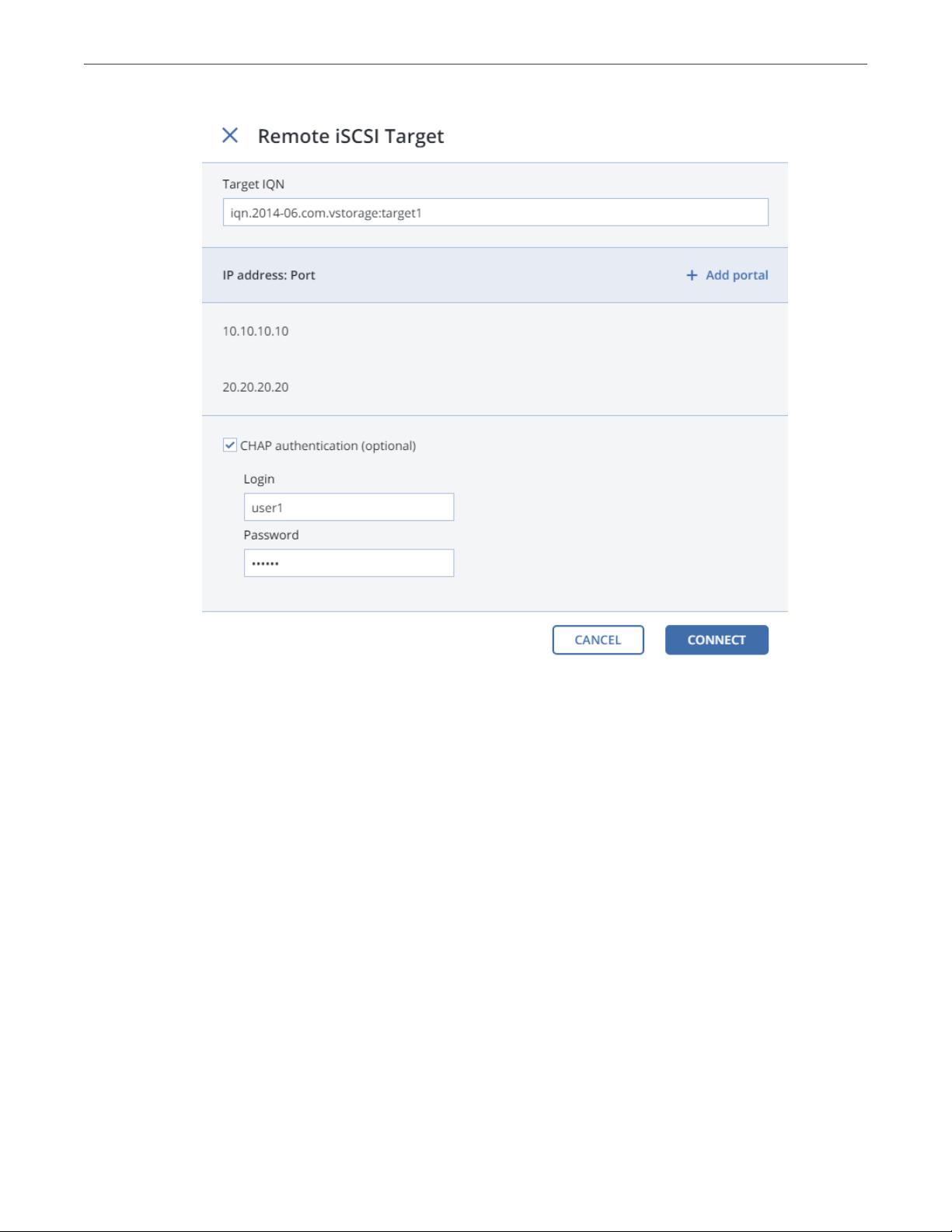
2. In the Remote iSCSI Target window, do the following:
1. Specify the IQN of the target.
2. In the Portal and Port fields, specify the target’s IP address and port (optional) and click the check
icon.
3. (Optional) If the target has multiple paths, click Add portal and configure it as in the previous step.
4. (Optional) If necessary, check CHAP authentication and specify the credentials.
5. Click Connect.
Acronis Cyber Infrastructure will connect the target (i.e. all its LUNs) and initiate it. Devices of the iSCSI type
will appear in the node’s DISKS list.
To remove the iSCSI target, click iSCSI Target, DELETE CONNECTION, and DELETE.
20
Page 29

Chapter 2. Managing the Storage Cluster
2.4.1 Assigning Disk Roles To Remote iSCSI Devices
If the node had already been in the cluster before you connected the iSCSI device to it, assign disk roles to all
its LUNs. To do this:
1. Select a disk with the iSCSI type and click Assign.
2. In the Choose role window, select Storage and click Done.
3. Repeat the above steps for every disk with the iSCSI type.
Even though you can assign Metadata or Cache roles to such disks, it is recommended only for single-node
ABGW installations with SAN-provided redundancy. For more information on disk roles, see Assigning Disk
Roles Manually (page 16).
2.5 Replacing Node Disks
If a disk installed in a storage cluster node fails, replace it as follows:
1. Open INFRASTRUCTURE > Nodes > <node> > Disks.
2. Select the failed disk, click Release.
3. In the Release disk window, click YES.
21
Page 30

Chapter 2. Managing the Storage Cluster
4. Replace the disk with a new one.
5. Back on INFRASTRUCTURE > Nodes > <node> > Disks, select the unassigned disk and click Assign.
6. In the Choose role window, select the required disk role and click DONE.
22
Page 31

The disk will be assigned the chosen role and added to the cluster.
Chapter 2. Managing the Storage Cluster
2.6 Releasing Nodes from the Storage Cluster
To release a node means to remove it from the cluster (e.g., for maintenance). As the node may be running
services needed by the cluster, do the following prior to releasing it to avoid cluster degradation:
1. If the node runs one of the three required metadata services, add a metadata role to another node.
You need to make sure that the cluster has at least three metadata services running at any time.
2. If the node has any access points, make sure that the same access points are configured on other
nodes in the cluster as well.
3. If the node is in an iSCSI target group, remove it from the target group first.
4. If the node has an S3 gateway or ABGW, reconfigure DNS for S3 and ABGW access points to remove the
node from DNS records. Next, release the node from S3 and ABGW in the corresponded sections of the
STORAGE SERVICES screen.
5. If the node is in the compute cluster, remove it from the compute cluster first.
6. Make sure the cluster has enough storage space to accommodate the data from the released node.
Once you initiate the release, the cluster will start replicating data chunks that were stored on the released
node and distributing them among other storage nodes in the cluster. Depending on the amount of data to
23
Page 32

Chapter 2. Managing the Storage Cluster
replicate, the process may take as much as several hours.
If necessary, you can also release a node forcibly, that is, without replication.
Warning: Releasing nodes forcibly may result in data loss.
To release a node from a cluster, do the following:
1. On the INFRASTRUCTURE > Nodes screen, click the node to release.
2. On the node overview screen, click Release.
3. If necessary, in the Release node window, check force to release the node forcibly (highly not
recommended).
4. Click Yes. The released node will return to the UNASSIGNED list on the INFRASTRUCTURE > Nodes
screen.
24
Page 33

Chapter 2. Managing the Storage Cluster
2.7 Removing Nodes from the Unassigned List
Nodes in the UNASSIGNED list can be completely removed from Acronis Cyber Infrastructure if they are not
in the high availability cluster.
To completely remove a node from the admin panel, do the following:
1. Select it in the UNASSIGNED list on the INFRASTRUCTURE > Nodes screen and click Remove (forget).
2. For security purposes, clean up node certificates and identity by deleting the following from the node:
# rm -rf /usr/libexec/vstorage-ui-backend/ca
# rm -rf /etc/nginx/ssl
# rm -f /etc/vstorage/host_id
# rm -f /etc/vstorage/vstorage-ui-agent.conf
Note: After such a cleanup, the only way to add the node back to the cluster is by re-installing Acronis
Cyber Infrastructure on it from scratch.
2.8 Re-Adding Nodes to the Unassigned List
Nodes removed from Acronis Cyber Infrastructure can be re-added to the UNASSIGNED list in two ways:
• By logging in to the node via SSH and running
/usr/libexec/vstorage-ui-agent/bin/register-storage-node.sh -m MN_ADDRESS -t TOKEN in the node’s
console (MN_ADDRESS is the management node IP address and TOKEN is the token obtained in the admin
panel).
Note: You can only do this if you have not cleaned up the node as described in Removing Nodes from
the Unassigned List (page 25).
• By reinstalling Acronis Cyber Infrastructure on the node from scratch.
25
Page 34

CHAPTER 3
Monitoring the Storage Cluster
Acronis Cyber Infrastructure uses the Prometheus monitoring system to monitor performance and
availability of both the entire cluster and its components. It also generates alerts, which you can configure to
be sent as notifications via e-mail.
3.1 Monitoring the Entire Cluster
The overall storage cluster statistics are available on the MONITORING > Dashboard screen. Pay attention
to the storage cluster status that can be one of the following:
HEALTHY
All cluster components are active and operate normally.
UNAVAILABLE
Not enough information about the cluster state (e.g., because the cluster is inaccessible).
DEGRADED
Some of the cluster components are inactive or inaccessible. The cluster is trying to heal itself, data
replication is scheduled or in progress.
ERROR
The cluster has too many inactive services, automatic replication is disabled. If the cluster enters this
state, troubleshoot the nodes or contact the support team.
To view the storage cluster statistics in full screen, click Fullscreen mode. To exit the fullscreen mode, press
Esc or Exit fullscreen mode.
For advanced monitoring, click Grafana dashboard. A separate browser tab will open with preconfigured
26
Page 35

Chapter 3. Monitoring the Storage Cluster
Grafana dashboards where you can manage existing dashboards, create new ones, share them between
users, configure alerting, etc. For more information, refer to Grafana documentation .
The default time interval for the charts is 12 hours. To zoom into a particular time interval, select the internal
with the mouse; to reset zoom, double click any chart.
3.1.1 I/O Activity Charts
The Read and Write charts show the history of the cluster I/O activity as the speed of read and write I/O
operations in megabytes per second and the number of read and write I/O operations per second (IOPS). For
example:
27
Page 36

3.1.2 Services Chart
Chapter 3. Monitoring the Storage Cluster
On the Services chart, you can monitor two types of services:
• Metadata services (MDS). The number all disks with the metadata role. Ensure that at least three
MDSes are running at all times.
• Chunk services (CS). The number of all disks with the storage role.
Typical statistics may look like this:
If some of the services were not in the healthy state for some time, these time periods will be highlighted in
red on the chart.
28
Page 37

Chapter 3. Monitoring the Storage Cluster
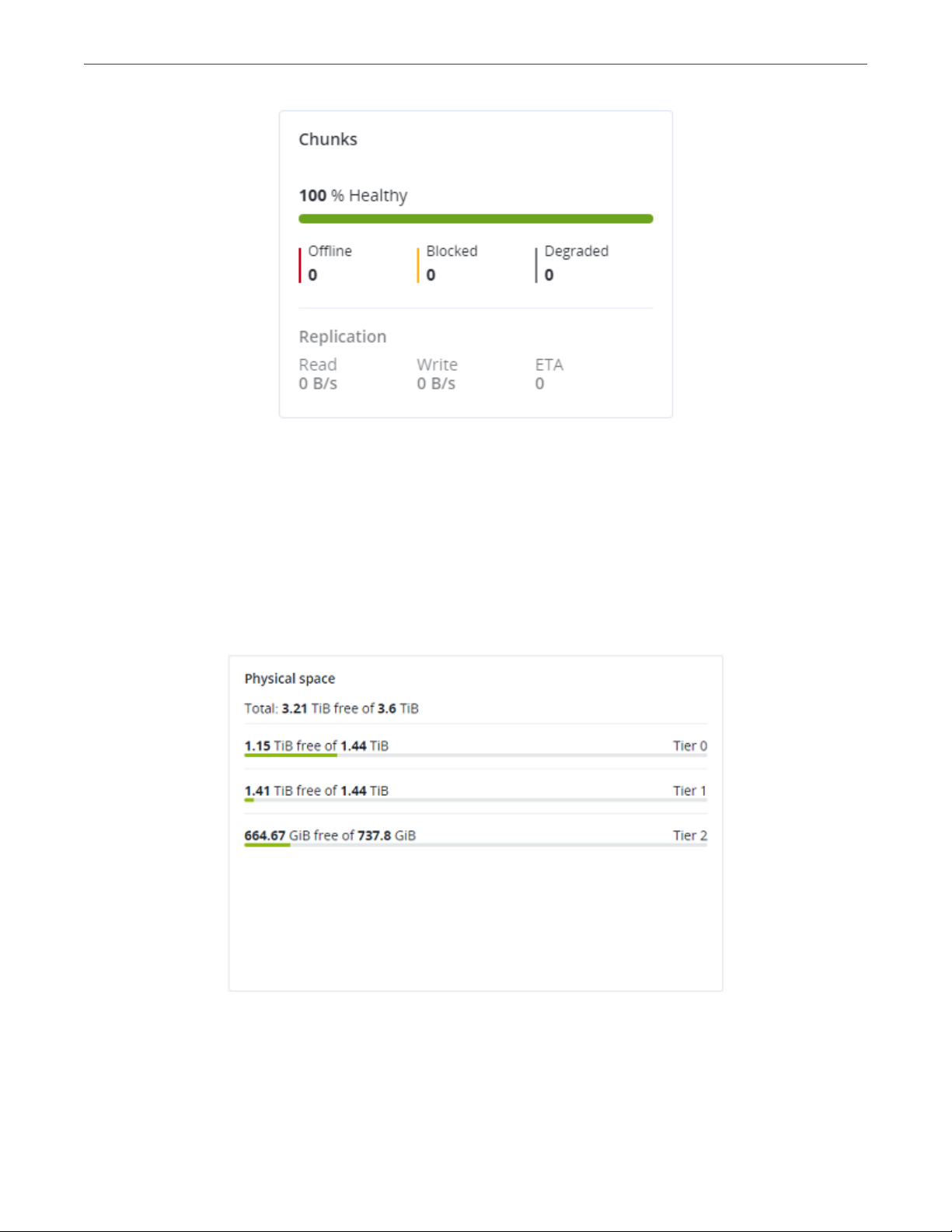
3.1.3 Chunks Chart
You can monitor the state of all chunks in the cluster on the Chunks chart. Chunks can be in the following
states:
Healthy
Number and percentage of chunks that have enough active replicas. The normal state of chunks.
Offline
Number and percentage of chunks all replicas of which are offline. Such chunks are completely
inaccessible for the cluster and cannot be replicated, read from or written to. All requests to an offline
chunk are frozen until a CS that stores that chunk’s replica goes online.
Get offline chunk servers back online as fast as possible to avoid losing data.
Blocked
Number and percentage of chunks which have fewer active replicas than the set minimum amount.
Write requests to a blocked chunk are frozen until it has at least the set minimum amount of replicas.
Read requests to blocked chunks are allowed, however, as they still have some active replicas left.
Blocked chunks have a higher replication priority than degraded chunks.
Having blocked chunks in the cluster increases the risk of losing data, so postpone any maintenance on
working cluster nodes and get offline chunk servers back online as fast as possible.
Degraded
Number and percentage of chunks whose active replicas are few but not below the set minimum. Such
chunks can be read from and written to. However, in the latter case a degraded chunk becomes urgent.
Healthy chunks are highlighted on the scale in green, offline in red, blocked in yellow, and degraded in grey.
For example:
29
Page 38
Chapter 3. Monitoring the Storage Cluster
The Replication section shows the information about replication activity in the cluster.
3.1.4 Physical Space Chart
The Physical space chart shows the current usage of physical space in the entire storage cluster and on each
particular tier. The used space includes the space occupied by all data chunks and their replicas plus the
space occupied by any other data.
30
Page 39

Chapter 3. Monitoring the Storage Cluster
3.1.4.1 Understanding Physical Space
The total physical disk space is a total of all the disk space on all storage disks on the same tier. The used
physical space is a total of all the user data on the storage disks of the same tier, considering the redundancy
mode. The free disk space is the total physical space minus the used physical space.
To better understand how physical disk space is calculated, consider the following example:
Table 3.1.4.1.1: Physical space example
Used/Total (Free), GiB
Tier 0, 3+2 encoding
(67% overhead)
Node 1 334/1024 (690) 134/512 (378) 50/256 (206)
Node 2 334/1024 (690) 133/512 (379) 50/256 (206)
Node 3 334/1024 (690) 133/512 (379)
Node 4 334/1024 (690)
Node 5 334/1024 (690)
Reported
summary
The cluster has ten disks with the storage role: five 1024 GiB disks are assigned to tier 0, three 512 GiB disks
to tier 1, and two 256 GiB disk to tier 2. There is no other data on the disks (like system files, for example).
Tier 0 stores 1000 GiB of user data in the 3+2 encoding mode. Tier 1 stores 200 GiB of user data in the 2
replicas mode. Tier 2 stores 100 GB of user data with no redundancy.
No matter what redundancy mode is used, the cluster attempts to spread data chunks evenly across disks of
the same tier.
1670/5120 (3450) 400/1536 (1136) 100/512 (412)
Tier 1, 2 replicas
(100% overhead)
Tier 2, no redundancy
In this example, the physical disk space on each tier is reported as follows:
• On tier 0, the total disk space is 5120 GiB, the used disk space is 1670 GiB, and the free disk space is
3450 GiB;
• On tier 1, the total disk space is 1536 GiB, the used disk space is 400 GiB, and the free disk space is 1136
GiB;
• On tier 2, the total disk space is 512 GiB, the used disk space is 100 GiB, and the free disk space is 456
GiB.
31
Page 40

Chapter 3. Monitoring the Storage Cluster
3.1.5 Logical Space Chart
The Logical space chart represents all the space allocated to different services for storing user data. This
includes the space occupied exclusively by user data. Replicas and erasure coding metadata are not taken
into account.
3.1.5.1 Understanding Logical Space
When monitoring disk space information in the cluster, keep in mind that logical space is the amount of free
disk space that can be used for storing user data in the form of data chunks and all their replicas. Once this
space runs out, no data can be written to the cluster.
To better understand how logical disk space is calculated, consider the following example:
• The cluster has three disks with the storage role. The first disk has 200 GB of space, the second one has
500 GB, and the third one has 1 TB.
• If the redundancy mode is set to three replicas, each data chunk must be stored as three replicas on
three different disks with the storage role.
In this example, the available logical disk space will be 200 GB, that is, equal to the capacity of the smallest
disk with the storage role. The reason is that each replica must be stored on a different disk. So once the
space on the smallest disk (i.e. 200 GB) runs out, no new chunk replicas can be created unless a new disk
with the storage role is added or the redundancy mode is changed to two replicas.
With the two replicas redundancy mode, the available logical disk space would be 700 GB, because the two
32
Page 41

Chapter 3. Monitoring the Storage Cluster
smallest disks combined can hold 700 GB of data.
3.2 Monitoring Nodes
Nodes added to the infrastructure are listed on the NODES screen, grouped by status. If the storage cluster
has not been created yet, you will only see nodes in the UNASSIGNED list. If the storage cluster exists, its
nodes will be listed on the screen.
The default time interval for the charts is 12 hours. To zoom into a particular time interval, select the internal
with the mouse; to reset zoom, double click any chart.
3.2.1 Node Statuses
A node can have one of the following statuses:
HEALTHY
All the storage services on the node are running.
OFFLINE
The node cannot be reached from the admin panel, although it may still be up and its services may be
running.
FAILED
One or more storage services on the node have failed.
UNASSIGNED
The node is not assigned to a cluster.
3.2.2 Monitoring Node Performance
To monitor the performance of a cluster node, open the NODES screen and click the node. On the node
overview screen, you will see performance statistics described below.
The overall statistics include:
• the number of CPUs and the amount of RAM,
• CPU usage, in percent over time,
33
Page 42

• RAM usage, in megabytes or gigabytes over time.
The DISKS section shows:
• the number of HDD and SSD drives and their statuses,
• node I/O activity over time on the read and write charts.
Chapter 3. Monitoring the Storage Cluster
The NETWORK section shows:
• the list of network interfaces and their statuses,
• the amount of transmitted (TX) and received (RX) traffic over time.
34
Page 43

Chapter 3. Monitoring the Storage Cluster
The following sections provide more information on disk and network usage.
3.2.3 Monitoring Node Disks
To monitor the usage and status of node disks, click the DISKS link on the node overview screen. You will see
a list of all disks on the node and their status icons.
A disk status icon shows the combined status of S.M.A.R.T. and the service corresponding to the disk role. It
can be one of the following:
OK The disk and service are healthy.
Failed
The service has failed or S.M.A.R.T. reported an error.
Releasing
The service is being released. When the process finishes, the disk status will change to OK.
To monitor performance of a particular disk, select it and click Performance. The Drive performance panel
will display the I/O activity of the disk.
To view information about the disk, including its S.M.A.R.T. status, click Details.
To have the disk blink its activity LED, select the disk, and click Blink. To have the disk stop blinking, click
Unblink.
3.2.3.1 Monitoring the S.M.A.R.T. Status of Node Disks
The S.M.A.R.T. status of all disks is monitored by a tool installed along with Acronis Cyber Infrastructure. Run
every 10 minutes, the tool polls all disks attached to nodes, including journaling SSDs and system disks, and
reports the results to the management node.
For the tool to work, make sure the S.M.A.R.T. functionality is enabled in node’s BIOS.
If a S.M.A.R.T. warning message is shown in the node status, one of that node’s disks is in pre-failure
condition and should be replaced. If you continue using the disk, keep in mind that it may fail or cause
performance issues.
Pre-failure condition means that at least one of these S.M.A.R.T. counters is not zero:
• Reallocated Sector Count
35
Page 44

Chapter 3. Monitoring the Storage Cluster
• Reallocated Event Count
• Current Pending Sector Count
• Offline Uncorrectable
3.2.4 Monitoring Node Network
To monitor the node’s network usage, click NETWORK on the node overview screen.
To display the performance charts of a specific network interface, select it in the list and click Performance.
When monitoring network performance, keep in mind that if the Receive and transmit errors chart is not
empty, the network is experiencing issues and requires attention.
To display the details of a network interface, click Details. The Network details panel shows the interface
state, bandwidth, MTU, MAC address, and all IP addresses.
3.3 Monitoring Storage Cluster Objects via SNMP
You can monitor cluster objects via the Simple Network Management Protocol (SNMP). The implementation
conforms to the same Structure of Management Information (SMI) rules as the data in the standard SNMP
context: all objects are organized in a tree; each object identifier (OID) is a series of integers corresponding to
tree nodes and separated by dots.
General information:
• The OID of the root subtree with all the objects you can monitor is 1.3.6.1.4.1.8072.161.1.
• The VSTORAGE-MIB.txt information base file is required to monitor the objects. You can download the
file at https://<admin_panel_IP>:8888/api/v2/snmp/mibs/.
The following subsections describe ways to enable and use SNMP to monitor cluster objects.
36
Page 45

Chapter 3. Monitoring the Storage Cluster
3.3.1 Enabling SNMP Access
To monitor cluster objects, enable the SNMP access on the node. Do the following in the admin panel:
1. Open UDP port 161 on the management node as follows:
1. On the INFRASTRUCTURE > Networks screen, click Edit.
2. Add the SNMP traffic type to your public network by ticking the corresponding checkbox.
3. Click Save to apply changes.
2. On the SETTINGS > Advanced settings > SNMP tab, check Enable SNMP on management node. The
network management system (SNMP monitor) will be enabled, giving you access to the cluster via the
SNMP protocol.
3. Click the provided link to download the MIB file and set it up in your SNMP monitor.
4. If required, have Acronis Cyber Infrastructure send SNMP traps to your SNMP monitor. Do the
following:
1. Check Send SNMP traps to this network management system.
2. Specify the IP address of the system, and, if required, change the default Port and Community.
3. If required, click SEND TEST TRAP to test the service.
37
Page 46

Chapter 3. Monitoring the Storage Cluster
5. Click SAVE to apply changes.
3.3.2 Accessing Storage Cluster Information Objects via SNMP
You can access storage cluster information objects with SNMP tools of your choice, e.g., the free Net-SNMP
suite for Linux.
To obtain storage cluster information on a node with the admin panel, place the MIB file to
/usr/share/snmp/mibs and run the snmpwalk command. For example:
# snmpwalk -M /usr/share/snmp/mibs -m VSTORAGE-MIB -v 2c -c public \
localhost:161 VSTORAGE-MIB:cluster
Typical output may be the following:
VSTORAGE-MIB::clusterName.0 = STRING: "cluster1"
VSTORAGE-MIB::healthStatus.0 = STRING: "healthy"
VSTORAGE-MIB::usedSpace.0 = Counter64: 173732322
VSTORAGE-MIB::totalSpace.0 = Counter64: 1337665179648
VSTORAGE-MIB::freeSpace.0 = Counter64: 1318963253248
VSTORAGE-MIB::licenseStatus.0 = STRING: "unknown"
VSTORAGE-MIB::licenseCapacity.0 = Counter64: 1099511627776
VSTORAGE-MIB::licenseExpirationStatus.0 = STRING: "None"
VSTORAGE-MIB::ioReadOpS.0 = Counter64: 0
VSTORAGE-MIB::ioWriteOpS.0 = Counter64: 0
VSTORAGE-MIB::ioReads.0 = Counter64: 0
VSTORAGE-MIB::ioWrites.0 = Counter64: 0
VSTORAGE-MIB::csActive.0 = Counter64: 11
VSTORAGE-MIB::csTotal.0 = Counter64: 11
VSTORAGE-MIB::mdsAvail.0 = Counter64: 4
VSTORAGE-MIB::mdsTotal.0 = Counter64: 4
<...>
3.3.2.1 Listening to SNMP Traps
To start listening to SNMP traps, do the following:
1. Configure the snmptrapd daemon to log SNMP traps, allow them to trigger executable actions, and
resend data to the network. To do this, add the following public community string to the
/etc/snmp/snmptrapd.conf file:
authCommunity log,execute,net public
2. Start the daemon and specify the MIB file:
38
Page 47

Chapter 3. Monitoring the Storage Cluster
# snmptrapd -M /usr/share/snmp/mibs -m VSTORAGE-MIB -n -f -Lf /tmp/traps.log
3. Send a test trap from the SETTINGS > Advanced settings > SNMP tab in the admin panel.
4. View the log file:
# tail -f /tmp/traps.log
2017-04-23 02:48:18 UDP: [127.0.0.1]:58266->[127.0.0.1]:162 [UDP: \
[127.0.0.1]:58266->[127.0.0.1]:162]:
SNMPv2-SMI::mib-2.1.3.0 = Timeticks: (1687405) 4:41:14.05 \
SNMPv2-SMI::snmpModules.1.1.4.1.0 = OID: VSTORAGE-MIB::generalAlert \
VSTORAGE-MIB::trapType = STRING: Test Case
STRING: This Is Text Message to end-user \
VSTORAGE-MIB::trapPriority = Counter64: 1
The test trap is considered a generalAlert.
VSTORAGE-MIB::trapMsg = \
3.3.3 Monitoring the Storage Cluster with Zabbix
To configure cluster monitoring in Zabbix, do the following:
1. On the SETTINGS > Advanced settings > SNMP tab, click the provided link to download a template for
Zabbix.
Note: The template is compatible with Zabbix 3.x.
2. In Zabbix, click Configuration > Templates > Import and Browse.
39
Page 48

Chapter 3. Monitoring the Storage Cluster
3. Navigate to the template, select it, and click Import.
4. Click Configuration > Hosts > Create host.
40
Page 49

Chapter 3. Monitoring the Storage Cluster
5. On the Host tab, do the following:
1. Specify the Host name of the management node and its Visible name in Zabbix.
2. Specify vstorage in the New group field.
3. Remove the Agent Interfaces section.
4. Add an SNMP interfaces section and specify the management node IP address.
6. On the Templates tab, click Select next to the Link new templates field.
7. In the Zabbix Server: Templates window, check the Template VStorageSNMP template and click Select.
41
Page 50

Chapter 3. Monitoring the Storage Cluster
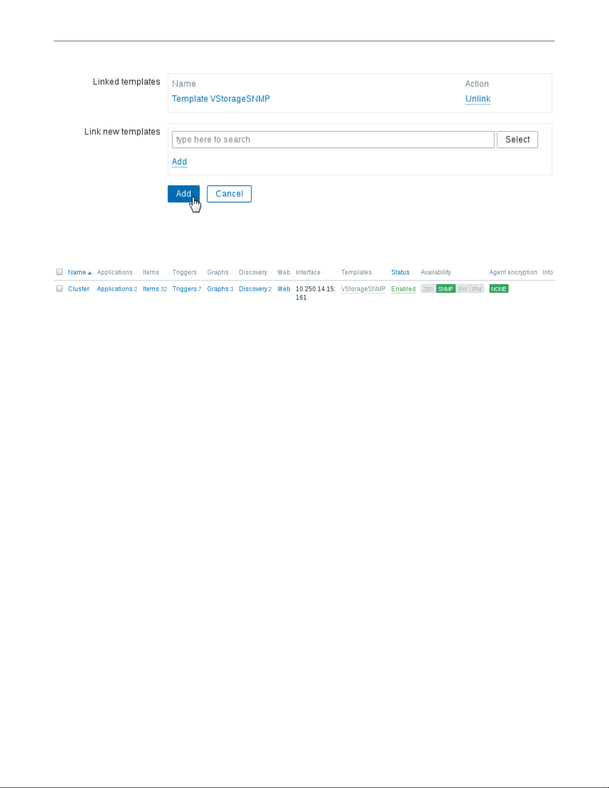
8. Back on the Templates tab, click the Add link in the Link new templates section. The VStorageSNMP
template will appear in the Linked templates group.
9. Having configured the host and added its template, click the Add button.
42
Page 51
Chapter 3. Monitoring the Storage Cluster
In a few minutes, the cluster’s SNMP label in the Availability column on the Configuration > Hosts screen will
turn green.
To monitor cluster’s parameters, open the Monitoring > Latest data screen, set the filter’s Host groups to
vstorage and click Apply.
You can create performance charts on the Configuration > Hosts > <cluster> > Graphs tab and a workplace
for them on the Monitoring > Screens tab.
3.3.4 Storage Cluster Objects and Traps
Cluster-related objects that you can monitor:
VSTORAGE-MIB:cluster
General cluster information.
VSTORAGE-MIB:csStatTable
Chunk server statistics table.
VSTORAGE-MIB:mdsStatTable
Metadata server statistics table.
VSTORAGE-MIB::clusterName
Cluster name.
VSTORAGE-MIB::healthStatus
Cluster health status.
43
Page 52

Chapter 3. Monitoring the Storage Cluster
VSTORAGE-MIB::usedSpace
The space occupied by all data chunks and their replicas plus the space occupied by any other data
stored on cluster nodes’ disks.
VSTORAGE-MIB::totalSpace
The total space on all cluster nodes’ disks.
VSTORAGE-MIB::freeSpace
The unused space on all cluster nodes’ disks.
VSTORAGE-MIB::licenseStatus
License status.
VSTORAGE-MIB::licenseCapacity
The maximum disk space available as defined by license.
VSTORAGE-MIB::licenseExpirationStatus
License expiration status.
VSTORAGE-MIB::ioReadOpS
Current read speed in operations per second.
VSTORAGE-MIB::ioWriteOpS
Current write speed in operations per second.
VSTORAGE-MIB::ioReads
Current read speed in bytes per second.
VSTORAGE-MIB::ioWrites
Current read write in bytes per second.
VSTORAGE-MIB::csActive
The number of active chunk servers.
VSTORAGE-MIB::csTotal
The total number of chunk servers.
VSTORAGE-MIB::mdsAvail
The number of running metadata servers.
VSTORAGE-MIB::mdsTotal
The total number of metadata servers.
44
Page 53

VSTORAGE-MIB::s3OsAvail
The number of running S3 object servers.
VSTORAGE-MIB::s3OsTotal
The total number of S3 object servers.
VSTORAGE-MIB::s3NsAvail
The number of running S3 name servers.
VSTORAGE-MIB::s3NsTotal
The total number of S3 name servers.
VSTORAGE-MIB::s3GwAvail
The number of running S3 gateways.
VSTORAGE-MIB::s3GwTotal
The total number of S3 gateways.
Chapter 3. Monitoring the Storage Cluster
CS-related objects that you can monitor:
VSTORAGE-MIB::csId
Chunk server identifier.
VSTORAGE-MIB::csStatus
Current chunk server status.
VSTORAGE-MIB::csIoReadOpS
Current read speed of a chunk server in operations per second.
VSTORAGE-MIB::csIoWriteOpS
Current write speed of a chunk server in operations per second.
VSTORAGE-MIB::csIoWait
The percentage of time spent waiting for I/O operations. Includes time spent waiting for
synchronization.
VSTORAGE-MIB::csIoReadS
Current read speed of a chunk server in bytes per second.
VSTORAGE-MIB::csIoWriteS
Current write speed of a chunk server in bytes per second.
MDS-related objects you can monitor:
45
Page 54

VSTORAGE-MIB::mdsId
Metadata server identifier.
VSTORAGE-MIB::mdsStatus
Current metadata server status.
VSTORAGE-MIB::mdsMemUsage
The amount of memory used by a metadata server.
VSTORAGE-MIB::mdsCpuUsage
The percentage of the CPU’s capacity used by a metadata server.
VSTORAGE-MIB::mdsUpTime
Time since the startup of a metadata server.
SNMP traps triggered by the specified alerts:
licenseExpired
Chapter 3. Monitoring the Storage Cluster
The license has expired.
tooFewClusterFreeLogicalSpace
Too few free space is left.
tooFewClusterFreePhysicalSpace
Too few physical space is left.
tooFewNodes
Too few nodes are left.
tooFewMdses
Too few MDSs are left.
generalAlert
Other.
3.4 Monitoring Storage Cluster Remotely
You can monitor your storage cluster via Prometheus remotely. To do this, you need to open a TCP port for
Prometheus API to be accessible from the outside.
To open a port, do the following:
46
Page 55

Chapter 3. Monitoring the Storage Cluster
1. On the INFRASTRUCTURE > Networks screen, click Edit and then Create traffic type.
2. In the Create traffic type window, specify a custom name in the Name field and 9090 in the Port field.
3. Click Create.
4. Add the newly created traffic type to your public network by ticking the corresponding checkbox.
5. Click Save to apply the changes.
You can now access the built-in Prometheus web-based user interface at
http://<admin_panel_IP_address>:9090. For more information on using Prometheus, refer to its
documentation.
If you have an external Grafana account and want to use it for monitoring Acronis Cyber Infrastructure, you
can add Prometheus as a data source as follows:
1. Log in into your Grafana user interface.
2. Click the cogwheel icon in the left menu and select Data Sources.
3. On the Data Sources tab, click Add data source.
4. On the Data Sources / New screen, specify the following parameters:
1. Enter a custom data source name in the Name field.
2. Set Type to Prometheus.
3. Enter http://<admin_panel_IP_address>:9090 in the URL field.
47
Page 56

Chapter 3. Monitoring the Storage Cluster
5. Click Save & Test.
If the specified parameters are correct, the Data source is working message will appear.
Using the newly added Prometheus data source, you can import the default Grafana dashboards from
Acronis Cyber Infrastructure or create new ones.
48
Page 57
Chapter 3. Monitoring the Storage Cluster
3.5 Viewing Alerts and Audit Log and Sending
E-mail Notifications
This section describes Acronis Cyber Infrastructure alerts and audit log and how to send out e-mail
notifications about alerts, warnings, and errors.
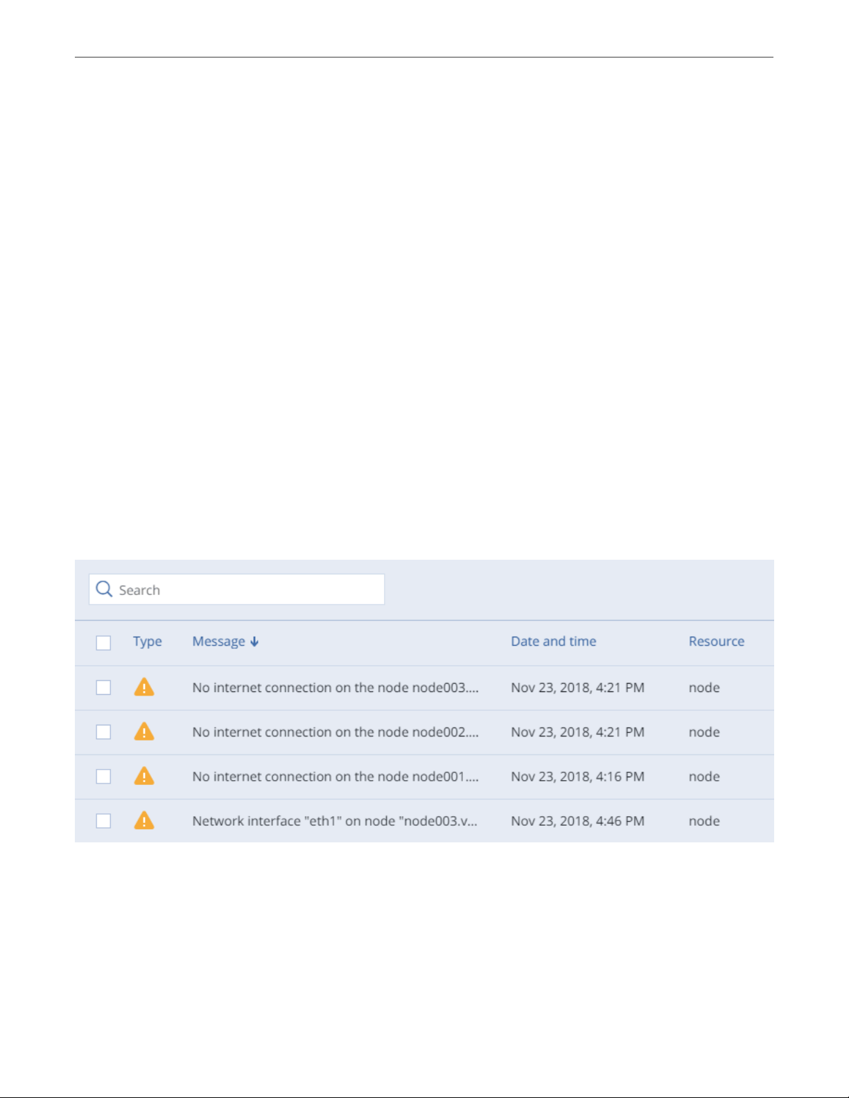
3.5.1 Viewing Alerts
The Alerts tab lists all the alerts logged by Acronis Cyber Infrastructure. An alert is generated and logged
each time one of the following conditions is met or events happen:
• a critical issue has happened with a cluster, its components (CS, MDS), disks, nodes, or services;
• cluster requires configuration or more resources to build or restore its health;
• network requires configuration or is experiencing issues that may affect performance;
• license is about to expire or has expired;
• cluster is about to or has run out of available space.
To view the details of an alert, select it on the MONITORING > Alerts screen and click Details in the menu on
the right.
Alerts can be ignored (deleted from the alerts list) or postponed for several hours. Postponed alerts
reappear in the list after some time.
49
Page 58

Chapter 3. Monitoring the Storage Cluster
To ignore or postpone an alert, select it and click the corresponding button.
3.5.2 Viewing Audit Log
The MONITORING > Audit log screen lists all management operations performed by users and their activity
events.
To view detailed information on a log entry, select it and click Show more details.
3.5.3 Sending E-mail Notifications
Acronis Cyber Infrastructure can send automatic e-mail notifications about errors, warnings, and alerts.
To set up e-mail notifications, do the following:
1. On the SETTINGS > Advanced settings > NOTIFICATIONS tab, specify the following information:
1. In the From and Sender name fields, the notification sender’s e-mail and name.
2. In the To field, one or more notification recipient e-mails, one per line.
3. In the User account and User password fields, the credentials of the notification sender
registered on the SMTP server.
4. In the SMTP server field, the DNS name of the SMTP server, either public (e.g., smtp.gmail.com) or
the one in your organization.
The management node must be able to access the SMTP server.
50
Page 59

Chapter 3. Monitoring the Storage Cluster
5. If required, a custom SMTP port the server uses.
6. In the Security field, the security protocol of the SMTP server.
2. Tick the checkboxes for alerts you want to be notified about.
3. Click Save.
To send a test e-mail, specify your e-mail registered on the SMTP server in both the From and To fields and
click Test.
51
Page 60

CHAPTER 4
Managing the Compute Cluster
4.1 Creating the Compute Cluster
Before creating a compute cluster, make sure the following requirements are met:
1. Network is set up according to recommendations in Managing Networks and Traffic Types (page 2). The
basic requirements are: (a) the traffic types VM private, VM public, and Compute API must be
assigned to networks; (b) the nodes to be added to the compute cluster must be connected to these
networks.
2. All nodes to be added to the compute cluster are connected to the same network with the VM public
traffic type.
3. High availability for the management node is enabled (see Enabling High Availability (page 202)).
Also take note of the following:
1. Creating the compute cluster prevents (and replaces) the use of the management node backup and
restore feature.
2. If nodes to be added to the compute cluster have different CPU models, consult the section “Setting
Virtual Machines CPU Model” in the Administrator’s Command Line Guide.
To create the compute cluster, open the COMPUTE screen, click Create compute cluster and do the
following in the Configure compute cluster window:
1. In the Nodes section, select nodes to add to the compute cluster, make sure the network state of each
selected node is Configured, and click Next.
Nodes in the management node high availability cluster are automatically selected to join the compute
52
Page 61

Chapter 4. Managing the Compute Cluster
cluster.
If node network interfaces are not configured, click the cogwheel icon, select networks as required, and
click Apply.
2. In the Public network section, enable IP address management if needed and provide the required
details for the public network.
With IP address management enabled, Acronis Cyber Infrastructure will handle virtual machine IP
addresses and provide the following features:
• Allocation pools. You can specify ranges of IP addresses that will be automatically assigned to VMs.
• Built-in DHCP server. Assigns IP addresses to virtual machines. With the DHCP server enabled, VM
network interfaces will automatically be assigned IP addresses: either from allocation pools or, if
there are no pools, from network’s entire IP range. With the DHCP server disabled, VM network
interfaces will still get IP addresses, but you will have to manually assign them inside VMs.
• Custom DNS servers. You can specify DNS servers that will be used by VMs. These servers will be
delivered to virtual machines via the built-in DHCP server.
With IP address management disabled:
• VMs connected to a network will be able to obtain IP addresses from DHCP servers in that network.
• Spoofing protection will be disabled for all VM network ports. Each VM network interface will
accept all traffic, even frames addressed to other network interfaces.
In any case, you will be able to manually assign static IP addresses from inside VMs.
53
Page 62

Chapter 4. Managing the Compute Cluster
If you choose to enable IP address management, select a physical network to connect the public virtual
network to and optionally specify its gateway. The subnet IP range in the CIDR format will be filled in
automatically. If you choose to leave IP address management disabled, select a physical network to
connect the public virtual network to.
The selected public network will appear in the list of virtual networks on compute cluster’s
NETWORKS
tab.
Click Next.
3. If you enabled IP address management on the previous step, you will move on to the DHCP and DNS
section. In it, enable or disable the built-in DHCP server and specify one or more allocation pools and
DNS servers. Click Next.
54
Page 63

Chapter 4. Managing the Compute Cluster
4. In the
Summary
section, review the configuration and click
Create cluster
.
You can monitor compute cluster deployment on the Compute screen.
55
Page 64

Chapter 4. Managing the Compute Cluster
4.2 Managing Compute Nodes
To make your infrastructure more resilient and redundant, you can create a high availability configuration of
three nodes.
Management node HA and compute cluster are tightly coupled, so changing nodes in one usually affects the
other. Take note of the following:
1. Each node in the HA configuration must meet the requirements to the management node listed in the
Installation Guide. If the compute cluster is to be created, its hardware requirements must be added as
well.
2. If the HA configuration has been created before the compute cluster, all nodes in it will be added to the
compute cluster.
3. If the compute cluster has been created before HA configuration, only nodes in the compute cluster can
be added to the HA configuration. For this reason, to add a node to HA configuration, add it to the
compute cluster first.
4. If both the HA configuration and compute cluster include the same three nodes, single nodes cannot be
removed from the compute cluster. In such a case, the compute cluster can be destroyed completely,
but the HA configuration will remain. This is also true vice versa, the HA configuration can be deleted,
but the compute cluster will continue working.
Nodes in the compute cluster are shown on the
Clicking a node, you can see the following information about it:
• node CPU and RAM usage,
• node name, status, and IP address,
• hosted virtual machines and their resource consumption.
Nodes
screen.
56
Page 65
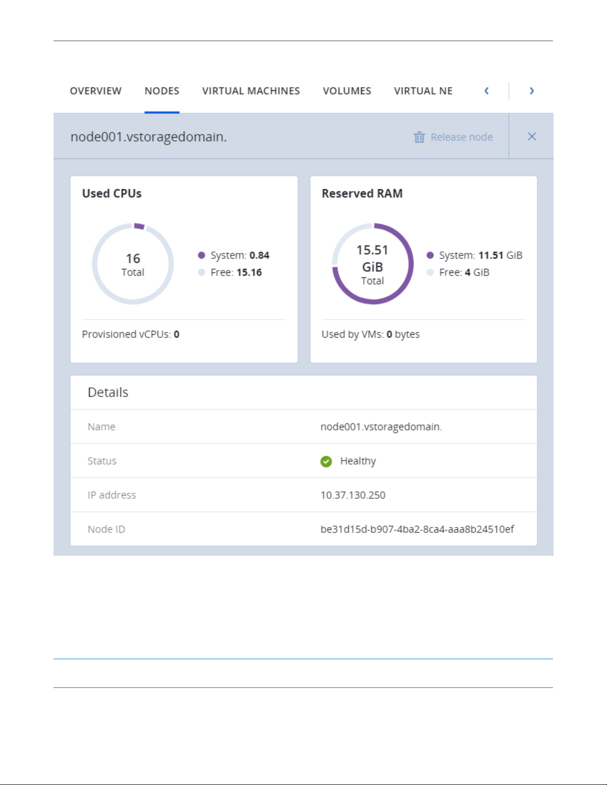
Chapter 4. Managing the Compute Cluster
The next subsections describe how to add nodes to and remove nodes from the compute cluster.
4.2.1 Adding Nodes to Compute Cluster
Note: Before changing nodes in the compute cluster, see limitations in Managing Compute Nodes (page 56).
57
Page 66

Chapter 4. Managing the Compute Cluster
To add one or more nodes to your compute cluster, do the following:
1. Click Add node on the Nodes screen. The Add node window will open.
2. If required, configure network on each node not marked green: click the cogwheel icon, assign
networks with the compute-related traffic types to node NICs, and click Apply.
3. Select nodes and click Add.
The added nodes will appear on the Nodes screen.
If several nodes are in the management node HA group, they all must be added to the compute cluster.
4.2.2 Releasing Nodes from Compute Cluster
Note: Before changing nodes in the compute cluster, see limitations in Managing Compute Nodes (page 56).
To release one or more nodes from the compute cluster, do the following:
1. On the Nodes screen, either
• select the nodes and click Release nodes above the list, or
• click the ellipsis icon next to a node and select Release, or
• click a node to open its details, then click Release node on the top toolbar.
2. In the Release node window, confirm the action by clicking Release.
The selected nodes will disappear from the Nodes screen.
58
Page 67

Chapter 4. Managing the Compute Cluster
If the node to be released has VMs on it, they must be migrated to other nodes first.
4.3 Managing Virtual Networks
In the compute cluster, you can create and manage two types of virtual networks:
Private
VXLAN-based overlay virtual networks that can be used for intercommunication between VMs. Each
private network is isolated from other private networks as well as public networks.
Public
Virtual networks that use IP address ranges of public physical networks. Such networks can be used to
provide Internet access to VMs.
Each public virtual network can use IP addresses of only one physical network.
In Acronis Cyber Infrastructure, virtual networking also includes virtual routers and floating public IP
addresses.
The next subsections explain the virtual network architecture and describe how to add, edit, and delete
virtual networks as well as manage virtual routers and floating IP addresses.
4.3.1 Virtual Network Architecture
Acronis Cyber Infrastructure supports distributed virtual switching on the basis of Open vSwitch. Open
vSwitch runs on every compute node and forwards network traffic between virtual machines on the same
node and between virtual machines and physical networks. Distributed virtual switching provides centralized
management and monitoring of virtual network configuration across all nodes in a compute cluster.
4.3.1.1 Private Network Connectivity
VXLAN technology used for private virtual networks allows creating logical L2 networks in L3 networks by
encapsulating (tunneling) Ethernet frames over UDP packets.
The physical representation of private network connectivity can be shown as follows:
59
Page 68

Chapter 4. Managing the Compute Cluster
On the figure above:
• Three virtual machines are distributed across the compute cluster and connected to two private virtual
networks via two virtual switches: VM1 and VM2 belong to one private virtual network, VM3 belongs to the
other one.
• For each virtual network, the DHCP server runs on the management node.
• The virtual router that runs on the management node connects the two private virtual networks and
the public virtual network created on top of the physical one, thus enabling connectivity between the
VMs from different private virtual networks.
• The compute nodes are connected to the physical switch via the eth0 network interfaces and reside in
one L2 segment.
• The eth0 network interfaces are connected to the physical network with the VM private and VM public
traffic types.
• The physical router provides access to public networks, such as the Internet.
60
Page 69

Chapter 4. Managing the Compute Cluster
Logically the private networking scheme can be represented as follows:
4.3.1.2 Public Network Connectivity
Public virtual networks are connected to physical networks on Layer 2.
The physical representation of public network connectivity can be shown as follows:
61
Page 70

Chapter 4. Managing the Compute Cluster
On the figure above:
• Five virtual machines are distributed across the compute cluster and connected to two public virtual
networks via two physical switches: VM1 and VM2 belong to one public virtual network, while VM3, VM4, and
VM5 belong to the other one.
• For each virtual network, the DHCP server runs on the management node.
• The compute nodes are connected to one physical switch via the eth0 network interfaces and to the
other physical switch via eth1 and reside in two separate L2 segments.
• The eth0 and eth1 network interfaces are connected to the physical networks with the VM public traffic
type.
• The physical router interconnects two public virtual networks created on top of the physical ones and
provides access to public networks, such as the Internet.
Logically the public networking scheme can be represented as follows:
62
Page 71

Chapter 4. Managing the Compute Cluster
4.3.2 Creating, Editing, and Deleting Virtual Networks
To add a new virtual network, do the following:
1. On the COMPUTE > Networks > NETWORKS tab, click Create virtual network.
2. In the Network configuration section, configure the network parameters:
1. Enable or disable IP address management.
With IP address management enabled, Acronis Cyber Infrastructure will handle virtual machine IP
addresses and provide the following features:
• Allocation pools. You can specify ranges of IP addresses that will be automatically assigned to
VMs.
• Built-in DHCP server. Assigns IP addresses to virtual machines. With the DHCP server enabled,
VM network interfaces will automatically be assigned IP addresses: either from allocation
pools or, if there are no pools, from network’s entire IP range. With the DHCP server disabled,
VM network interfaces will still get IP addresses, but you will have to manually assign them
inside VMs.
• Custom DNS servers. You can specify DNS servers that will be used by VMs. These servers will
be delivered to virtual machines via the built-in DHCP server.
With IP address management disabled:
• VMs connected to a network will be able to obtain IP addresses from DHCP servers in that
network.
63
Page 72

Chapter 4. Managing the Compute Cluster
• Spoofing protection will be disabled for all VM network ports. Each VM network interface will
accept all traffic, even frames addressed to other network interfaces.
In any case, you will be able to manually assign static IP addresses from inside VMs.
2. Choose network type.
3. Provide network details depending on type:
• For a private network, specify a name. If IP address management is enabled, specify network’s
IPv4 address range in Subnet CIDR. Optionally specify a gateway. If you leave the Gateway
field blank, the gateway will be omitted from network settings.
• For a public network, specify a name and choose a physical network with the VM public traffic
type (that is not already used by a public network). If IP address management is enabled,
optionally specify a gateway. If you leave the Gateway field blank, the gateway will be omitted
from network settings. The Subnet CIDR field will be filled in automatically. Optionally, select
the Share between all projects checkbox. With the disabled option, the public network will
only be available in the admin project of the Default domain.
Click Next.
64
Page 73

Chapter 4. Managing the Compute Cluster
3. If you enabled IP address management on the previous step, you will move on to the DHCP and DNS
section. In it, enable or disable the built-in DHCP server and specify one or more allocation pools and
DNS servers. Click Next.
4. In the Summary section, review the configuration and click Add virtual network.
65
Page 74

Chapter 4. Managing the Compute Cluster
To view and edit parameters of a virtual network, click it on the NETWORKS tab. On the virtual network
panel, you can change the virtual network name, gateway, DHCP settings, allocation pools, and DNS servers.
To do this, click the pencil icon, enter a new value, and click the check mark icon to confirm.
To delete a virtual network, click the ellipsis icon next to it and Delete. To remove multiple virtual networks at
once, select them and click Delete. Before deleting a virtual network, make sure no VMs are connected to it.
4.3.3 Managing Virtual Routers
Virtual routers provide L3 services such as routing and Source Network Address Translation (SNAT) between
private and public networks or different private networks:
• a virtual router between private and public networks provides access to public networks, such as the
Internet, for VMs connected to this private network;
• a virtual router between different private networks provides network communication for VMs
connected to these private networks.
66
Page 75

Chapter 4. Managing the Compute Cluster
A virtual router has two types of ports:
• an external gateway that is connected to a public network,
• an internal port that is connected to a private network.
Note: A router can only connect networks with enabled IP management.
To create a virtual router, do the following:
1. On the COMPUTE > Networks > NETWORKS tab, make sure the virtual networks that are to be
connected to a router have a gateway specified.
2. Navigate to the ROUTERS tab and click Add router.
3. In the Add router window:
1. Specify a router name.
2. From the Network drop-down menu, select a public network through which external access will
be provided via an external gateway. The new external gateway will pick an unused IP address
from the selected public network.
3. In the Add internal interfaces section, select one or more private networks to connect to a router
via internal interfaces. The new internal interfaces will attempt to use the gateway IP address of
the selected private networks by default.
4. Optionally, select or deselect the SNAT checkbox to enable or disable SNAT, respectively, on the
external gateway of the router. With SNAT enabled, the router replaces VM private IP addresses
with the public IP address of its external gateway.
67
Page 76

Chapter 4. Managing the Compute Cluster
4. Click Create.
To edit a router name, click the ellipsis icon next to it and Rename.
To remove a virtual router, click the ellipsis icon next to it and Delete. To remove multiple virtual networks at
once, select them and click Delete. Before deleting a virtual router, make sure no floating IP addresses are
associated with any network it is connected to.
4.3.3.1 Managing Router Interfaces
You can add an external router interface as follows:
Note: To change an external gateway, remove the existing one first.
1. On Routers screen, click the router name to open the list of its interfaces.
68
Page 77

Chapter 4. Managing the Compute Cluster
2. Click Add.
3. In the Add interface window, do the following:
1. Choose External gateway.
2. From the Network drop-down menu, select a public network to connect to the router. The new
interface will pick an unused IP address from the selected public network. You can also provide a
specific IP address from the selected public network to assign to the interface in the IP address
field.
3. Optionally, select or deselect the SNAT checkbox to enable or disable SNAT, respectively, on the
external gateway of the router. With SNAT enabled, the router replaces VM private IP addresses
with the public IP address of its external gateway.
4. Click Add.
To edit the external gateway parameters, click the ellipsis icon next to it and Edit. In the Edit interface
window, you can change the external gateway IP address and enable or disable SNAT on it. To save your
changes, click Save.
69
Page 78

Chapter 4. Managing the Compute Cluster
You can add an internal router interface as follows:
1. On Routers screen, click the router name to open the list of its interfaces.
2. Click Add.
3. In the Add interface window, select a network to connect to the router from the Network drop-down
menu. The new interface will attempt to use the gateway IP address of the selected private network by
default. If it is in use, specify an unused IP address from the selected private network to assign to the
interface in the IP address field.
4. Click Add.
To remove a router interface, click the ellipsis icon next to it and Delete. To remove multiple interfaces at
once, select them and click Delete.
4.3.3.2 Managing Static Routes
You can also configure static routes of a router by manually adding entries into its routing table. This can be
useful, for example, if you do not need a mutual connection between two private networks and want only
one private network to be accessible from the other.
Consider the following example:
70
Page 79

Chapter 4. Managing the Compute Cluster
• the virtual machine vm1 is connected to the private network private1 (192.168.128.0/24) via the network
interface with IP address 192.168.128.10,
• the virtual machine vm2 is connected to the private network private2 (192.168.30.0/24) via the network
interface with IP address 192.168.30.10,
• the router router1 connects the network private1 to the public network via the external gateway with
the IP address 10.94.129.73,
• the router router2 connects the network private2 to the public network via the external gateway with
the IP address 10.94.129.74.
To be able to access vm2 from vm1, you need to add a static route for router1, specifying the CIDR of private2,
that is 192.168.30.0/24, as the destination subnet and the external gateway IP address of router2, that is
10.94.129.74, as the next hop IP address. In this case, when an IP packet for 192.168.30.10 reaches router1, it
will be forwarded to router2 and then to vm2.
To create a static route for a router, do the following:
1. On the STATIC ROUTES tab of a virtual router, click Add static route.
2. In the Add static route window, specify the destination subnet range and mask in CIDR notation and
the next hop’s IP address. The next hop’s IP address must belong to one of the networks that the router
is connected to.
3. Click Add.
71
Page 80

Chapter 4. Managing the Compute Cluster
To edit a static route, click the ellipsis icon next to it and Edit. In the Edit static route window, change the
desired parameters and click Save.
To remove a static route, click the ellipsis icon next to it and Delete. To remove multiple routes at once,
select them and click Delete.
4.3.4 Managing Floating IP Addresses
A virtual machine connected to a virtual private network can be accessed from public networks, such as the
Internet, by means of a floating IP address. Such an address is picked from a public network and mapped to
VM’s private IP address. The floating and private IP addresses are used at the same time on the VM’s network
interface. The private IP address is used to communicate with other VMs on the private network. The floating
IP address is used to access the VM from public networks. The VM guest operating system is unaware of the
assigned floating IP address.
Note the following prerequisites:
1. A VM must have a fixed private IP address.
2. A virtual router must connect the public network from which a floating IP will be picked with VM’s
private network.
You can create a floating IP address and assign it to a VM as follows:
1. On the COMPUTE > Networks > FLOATING IPS tab, click Add floating IP.
2. In the Add floating IP address, select a public network from which a floating IP will be picked and a VM
network interface with a fixed private IP address.
3. Click Add.
72
Page 81

Chapter 4. Managing the Compute Cluster
A floating IP address can be re-assigned to another virtual machine. Do the following:
1. Click the ellipsis icon next to the floating IP address and then click Unassign.
2. Once the VM name disappears in the Assigned to column, click the ellipsis icon again and choose
Assign.
3. In the Assign floating IP address window, select a VM network interface with a fixed private IP address.
4. Click Assign.
To remove a floating IP address, unassign it from a VM as described above, then click the ellipsis icon again
and choose Delete.
4.4 Managing Storage Policies
A storage policy in Acronis Cyber Infrastructure is a group of parameters that define how to store VM
volumes: how redundant they must be and on what storage tier they need to be located.
When you deploy the compute cluster, a default storage policy is created that enforces the best replication
scheme allowed by the number of nodes in the storage cluster. The default policy cannot be deleted or
renamed and is always applied to uploaded images and base volumes created from these images.
Note: A base volume is created from a source image when you deploy a VM. It is not used directly by a VM,
but all volumes that a VM actually uses (which are listed on the VOLUMES tab) are in fact deltas (differences)
from the base volume. It is important to keep base volumes available as VM volumes depend on them. For
that, you need the default storage policy to enforce multiple replicas.
If the storage cluster does not have enough nodes to enable multiple replicas (not recommended), you can
adjust the default storage policy once you add more nodes to the storage cluster. It will be applied to images
and base volumes that already exist in the compute cluster.
To apply custom redundancy schemes to VM volumes, you can create custom storage policies in addition to
the default one. To create a custom storage policy, do the following:
1. On the COMPUTE > Storage > STORAGE POLICIES tab, click Create storage policy.
2. In the Create storage policy window, specify a name and select the following:
73
Page 82
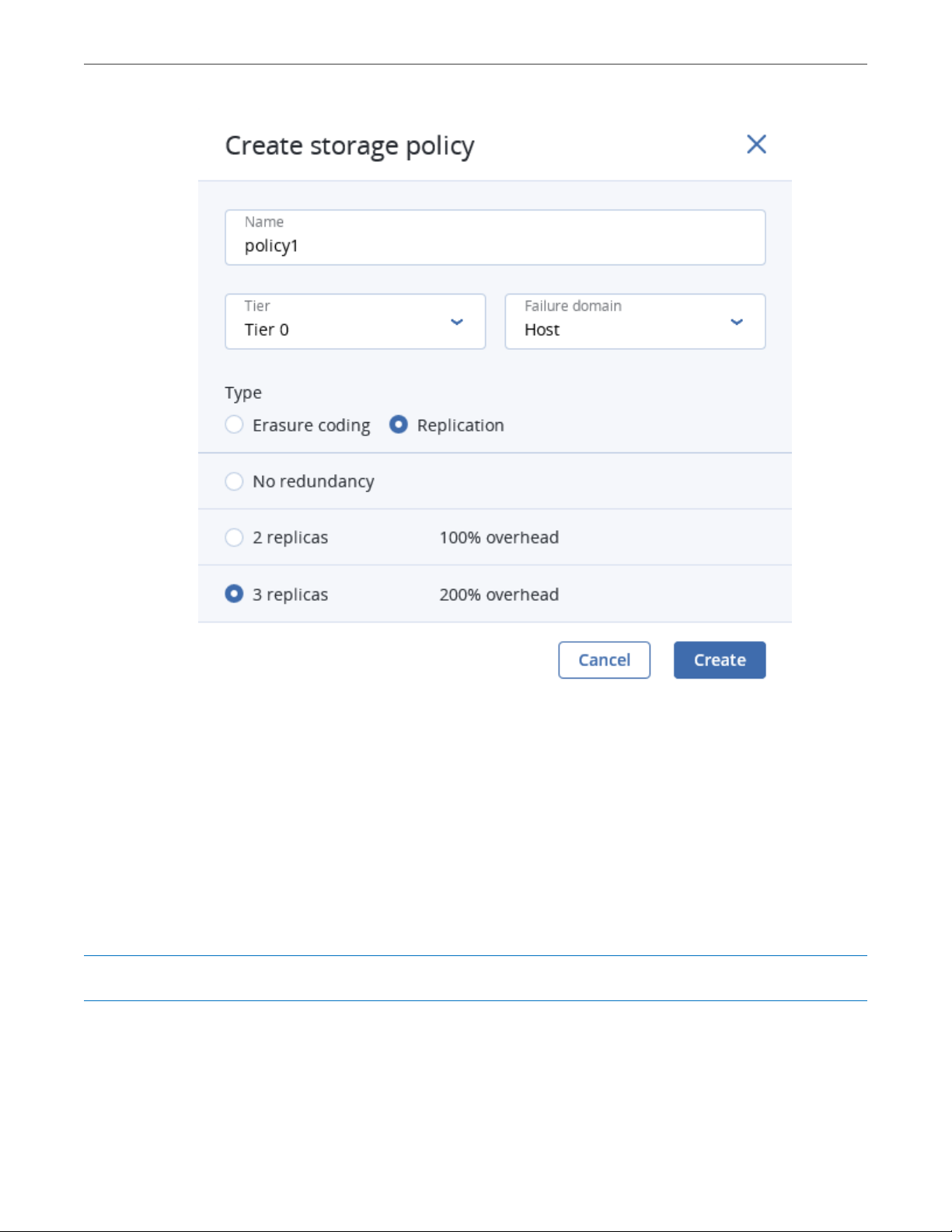
Chapter 4. Managing the Compute Cluster
1. In Tier, a tier to store volumes on.
2. In Failure domain, a placement policy for data pieces or replicas.
3. In Type, a data redundancy type and mode.
3. Click Create.
To edit a policy, select it and click the pencil icon next to a parameter you need to change. To change the
redundancy mode of the policy, click the ellipsis button next to it and click Edit redundancy.
Note: You cannot change redundancy type of policies used by volumes. You can create new policies instead.
After a policy is modified, the changes are applied to every volume governed by it.
To remove a policy, select it and click Delete policy. A policy cannot be removed if it governs existing
74
Page 83

Chapter 4. Managing the Compute Cluster
volumes.
4.5 Managing Images
Acronis Cyber Infrastructure allows you to upload ISO images and templates that can be used to create VM
volumes. An ISO image is a typical OS distribution that needs to be installed on disk. In turn, a template is a
ready volume in the QCOW2 format with an installed operating system and applications and a set minimum
size. Many OS vendors offer templates of their operating systems under the name “cloud images”. For a list
of guest OSes supported in virtual machines, see Supported Guest Operating Systems (page 77).
Note: Images are stored according to the default storage policy.
To add an image, do the following:
1. On the COMPUTE > Virtual machines > IMAGES tab, click Add image.
2. In the Add image window, do the following:
1. Click Browse and select a template or ISO file.
2. Specify an image name to be shown in the admin panel.
3. Select a correct OS type from the drop-down list.
Important: OS type affects VM parameters like hypervisor settings. VMs created from an image
with a wrong OS type may not work correctly, e.g., crash.
75
Page 84

Chapter 4. Managing the Compute Cluster
3. Optionally, select the Share between all projects checkbox. With the option disabled, the image will
only be available in the admin project of the Default domain.
4. Click Add to upload the image.
The admin panel will show the upload progress.
Important: Do not reload the page while the image is being uploaded or the process will fail.
To edit an image, select it and click the pencil icon next to a parameter you need to change.
To remove an image, click the ellipsis button next to it and Delete.
For information on how to create Linux templates, see the “Creating Linux Templates” section of the
Administrator’s Command Line Guide.
76
Page 85

Chapter 4. Managing the Compute Cluster
4.6 Managing Virtual Machines
Each virtual machine (VM) is an independent system with an independent set of virtual hardware. Its main
features are the following:
• A virtual machine resembles and works like a regular computer. It has its own virtual hardware.
Software applications can run in virtual machines without any modifications or adjustment.
• Virtual machine configuration can be changed easily, e.g., by adding new virtual disks or memory.
• Although virtual machines share physical hardware resources, they are fully isolated from each other
(file system, processes, sysctl variables) and the compute node.
• A virtual machine can run any supported guest operating system.
The following table lists the current virtual machine configuration limits:
Table 4.6.1: Virtual machine hardware
Resource Limit
RAM 1 TiB
CPU 48 logical CPUs
Storage 15 volumes, 512 TiB each
Network 15 NICs
A logical CPU is a core (thread) in a multicore (multithreading) processor.
4.6.1 Supported Guest Operating Systems
The following guest operating systems have been tested and are supported in virtual machines:
Table 4.6.1.1: Windows guest operating systems
Operating System Edition Architecture
Windows Server 2019 Essentials, Standard, Datacenter x64
Windows Server 2016 Essentials, Standard, Datacenter x64
Windows Server 2012 R2 Essentials, Standard, Datacenter x64
Windows Server 2012 Standard, Datacenter x64
Continued on next page
77
Page 86

Chapter 4. Managing the Compute Cluster
Table 4.6.1.1 – continued from previous page
Operating System Edition Architecture
Windows Server 2008 R2 Standard, Datacenter x64
Windows Server 2008 Standard, Datacenter x64
Windows 10 Home, Professional, Enterprise, Enterprise 2016
x64
LTSB
Windows 8.1 Home, Professional, Enterprise x64
Windows 7 Home, Professional, Enterprise x64
Table 4.6.1.2: Linux guest operating systems
Operating System Architecture
CentOS 7.x x64
CentOS 6.x x64
RHEL 8.x x64
RHEL 7.x x64
Debian 9.x x64
Ubuntu 18.04.x x64
Ubuntu 16.04.x x64
4.6.2 Creating Virtual Machines
Before you proceed to creating VMs, check that you have these:
• A guest OS source (see Managing Images (page 75)):
•
a distribution ISO image of a guest OS to install in the VM, or
•
a boot volume template, or
•
a boot volume
Note: To obtain a boot volume, create a volume as described in Managing Volumes
(page 93), attach it to a VM, install an operating system in it, then delete the VM.
• A storage policy for volumes (see Managing Storage Policies (page 73))
78
Page 87

Chapter 4. Managing the Compute Cluster
• A flavor (see Managing Flavors (page 100))
• One or more virtual networks (see Managing Virtual Networks (page 59))
• An SSH key (see Managing SSH Keys (page 101))
Note: You can specify an SSH key only when creating VMs from a template or boot volume.
Note: Virtual machines are created with the host CPU model by default. Having compute nodes with
different CPUs may lead to live migration issues. To avoid them, you can manually set CPU model for all new
VMs as described in the Administrator’s Command Line Guide.
To create a VM, do the following:
1. On the COMPUTE > Virtual machines > VIRTUAL MACHINES tab, click Create virtual machine. A
window will open where you will need to specify VM parameters.
2. Specify a name for the new VM.
3. In Deploy from, choose Volume if you have a boot volume or want to create one. Otherwise, choose
79
Page 88

Chapter 4. Managing the Compute Cluster
Image.
4. Depending on your choice, click the pencil icon in the Volumes or Image section and do one of the
following:
• In the Images window, select the ISO image or template and click Done.
• In the Volumes window, do one of the following:
•
If you have prepared a volume with an installed guest OS, click Attach, find and select the
volume, and click Done.
80
Page 89

Chapter 4. Managing the Compute Cluster
5. Optionally, in the Volumes window, click Add or Attach to create or attach any other volumes you
need. To select a volume as bootable, place it first in the list by clicking the up arrow button next to it.
6. In the Flavor window, choose a flavor and click Done.
81
Page 90

Chapter 4. Managing the Compute Cluster
7. In the network window, click Add, select a virtual network interface and click Add. It will appear in the
Network interfaces list.
You can edit additional parameters of newly added network interfaces, like IP and MAC addresses and
spoofing protection. To do this, click interface’s ellipsis icon, then Edit, and set parameters in the Edit
network interface window.
You will not be able to edit these parameters later. Instead, you will be able to delete the old network
interface and replace it with a new one.
82
Page 91

Chapter 4. Managing the Compute Cluster
Click Done.
8. (Optional) If you are deploying the VM from a template or boot volume (not an ISO image), you can
specify the following:
• An SSH key to be injected into the VM. To do it, select an SSH key in the Select an SSH key window,
and click Done.
83
Page 92

Chapter 4. Managing the Compute Cluster
Note: To be able to connect to the VM via SSH, make sure the VM template or boot volume has
cloud-init and OpenSSH installed (see the “Creating SSH-Enabled Templates” section in the
Administrator’s Command Line Guide).
• User data to customize the VM after launch. To do it, write a script in the Customization script
field or browse a file on your local server to load the script from.
You can specify user data in one of two formats: cloud-config or shell script. To inject a script in a
Windows VM, refer to the Cloudbase-Init documentation.
84
Page 93

Chapter 4. Managing the Compute Cluster
Note: For the guest OS to be customizable, make sure the VM template or boot volume has
cloud-init installed.
9. Back in the Create virtual machine window, click Deploy to create and boot the VM.
10. If you are deploying the VM from an ISO image (not a boot volume template or a volume with a
pre-installed guest OS), select the VM, click Console, and install the guest OS using the built-in VNC
console.
11. (Optional) If you are deploying the VM from a prepared template with an injected SSH key, you can
connect to it via SSH using the username and the VM IP address:
• For Linux templates, enter the username that is default for the cloud image OS (for example, for a
CentOS cloud image, the default login is centos).
85
Page 94

Chapter 4. Managing the Compute Cluster
• For Windows templates, enter the username that you specified during Cloudbase-Init installation.
• For VMs customized with user data, enter the username specified in the script.
For example:
# ssh myuser@10.10.10.10
4.6.3 Virtual Machine Actions Overview
After you create a virtual machine, you can manage it using the actions available for its current state. To see
the full list of available actions, click the ellipsis button next to a VM or on top of its panel. Actions include:
• Run powers up a VM.
• Console connects to running VMs via the built-in VNC console. In the console browser window, you can
send a key combination to a VM, take a screenshot of the console window, and download the console
log.
• Reboot soft-reboots a running VM.
• Shut down gracefully shuts down a running VM.
• Hard reboot cuts off and restores power, then starts a VM.
• Power off forcibly cuts off power from a VM.
• Shelve unbinds a stopped VM from the node it is hosted on and releases its reserved resources such as
CPU and RAM. A shelved VM remains bootable and retains its configuration, including the IP addresses.
Virtual machines in other states can be shelved by clicking Shut down or Power off and selecting the
checkbox Shelve virtual machine in the confirmation window.
• Unshelve spawns a shelved VM on a node with enough resources to host it.
• Suspend saves the current VM state to a file.
This may prove useful, for example, if you need to restart the host but do not want to quit the
applications currently running in the VM or restart its guest OS.
• Resume restores a VM from suspended state.
• Download console log downloads the console log. Make sure logging is enabled inside the VM,
otherwise the log will be empty (for more information, see Enabling Logging inside Virtual Machines
(page 87)).
86
Page 95

Chapter 4. Managing the Compute Cluster
Examining console logs may be useful in troubleshooting failed virtual machines.
• Reset state resets the VM stuck in a failed or transitional state to its last stable state: active, shut down
or shelved.
• Delete removes a VM from the compute cluster.
• Migrate moves a VM to another node in the compute cluster (for more information, see Migrating
Virtual Machines (page 88)).
4.6.4 Enabling Logging inside Virtual Machines
VM’s console log will contain log messages only if the TTY1 and TTYS0 logging levels are enabled inside the
VM. For example, you can enable them as follows in Linux VMs:
1. Add the line GRUB_CMDLINE_LINUX_DEFAULT="console=tty1 console=ttyS0" to the file /etc/default/grub.
2. Depending on the boot loader, run either
# grub-mkconfig -o /boot/grub/grub.cfg
or
# grub2-mkconfig -o /boot/grub2/grub.cfg
3. Reboot the VM.
In Windows VMs, you can enable Emergency Management Services (EMS) console redirection for this
purpose. Do the following:
1. Start Windows PowerShell with administrator privileges.
2. In the PowerShell console, set the COM port and baud rate for EMS console redirection. As Windows
VMs have only the COM1 port with the transmission rate of 9600 bps, run:
bcdedit /emssettings EMSPORT:1
3. Enable EMS for the current boot entry:
bcdedit /ems on
You may also enable driver status logging to see the list of loaded drivers. This can be useful for
troubleshooting a faulty driver or long boot process. You can do this as follows:
1. Start System Configuration with administrator privileges.
87
Page 96

Chapter 4. Managing the Compute Cluster
2. In the System Configuration windows, open the Boot tab, select the checkboxes OS boot information
and Make all boot settings permanent.
3. Confirm the changes and restart the system.
4.6.5 Migrating Virtual Machines
VM migration helps facilitate cluster upgrades and workload balancing between compute nodes. Acronis
Cyber Infrastructure allows you to perform two types of migration:
• Cold migration for stopped and suspended virtual machines
• Hot migration for running virtual machines (allows you to avoid VM downtime)
For both migration types, a virtual machine is migrated between compute nodes using shared storage, so no
block device migration takes place.
Hot migration consists of the following steps:
1. All VM memory is copied to the destination node while the virtual machine keeps running on the source
node. If a VM memory page changes, it is copied again.
2. When only a few memory pages are left to copy, the VM is stopped on the source node, the remaining
pages are transferred, and the VM is restarted on the destination node.
Large virtual machines with write-intensive workloads write to memory faster than memory changes can be
transferred to the destination node, thus preventing migration from converging. For such VMs, the
auto-converge mechanism is used. When a lack of convergence is detected during live migration, VM’s vCPU
execution speed is throttled down, which also slows down writing to VM memory. Initially, virtual machine’s
vCPU is throttled by 20% and then by 10% during each iteration. This process continues until writing to VM
memory slows down enough for migration to complete or the VM vCPU is throttled by 99%.
Note: Virtual machines are created with the host CPU model by default. Having compute nodes with
different CPUs may lead to live migration issues. To avoid them, you can manually set CPU model for all new
VMs as described in the Administrator’s Command Line Guide.
To migrate a VM, do the following:
1. On the COMPUTE > Virtual machines > VIRTUAL MACHINES tab, click a VM to migrate, click the
ellipsis button and choose Migrate.
88
Page 97

Chapter 4. Managing the Compute Cluster
2. In the new window, specify the destination node:
• Auto. Automatically select the optimal destination among cluster nodes based on available CPU
and RAM resources.
• Select the destination node manually from the drop-down list.
3. By default, running VMs are migrated live. You can change the migration mode to offline by ticking the
Cold migration checkbox. A VM will be stopped and restarted on the destination node after migration.
4. Click Migrate to reserve resources on the destination node and start migration.
The admin panel will show the migration progress.
89
Page 98

Chapter 4. Managing the Compute Cluster
4.6.6 Reconfiguring and Monitoring Virtual Machines
To monitor virtual machine’s CPU, storage, and network usage, select the VM and open the Monitoring tab.
To reconfigure a VM, select it and, on the Overview tab, click the pencil icon next to a parameter you need to
change. You cannot do the following:
• Change, detach, or delete the boot volume
• Manage non-boot volumes except attaching and detaching
• Modify previously added network interfaces
• Attach and detach network interfaces to and from shelved VMs
• Change the flavor for running and shelved VMs
4.6.7 Configuring Virtual Machine High Availability
High availability keeps virtual machines operational if the node they are located on fails due to kernel crash,
power outage and such or becomes unreachable over the network. Graceful shutdown is not considered a
failure event.
Important: The compute cluster can survive the failure of only one node.
In the event of failure, the system will attempt to evacuate affected VMs automatically, that is, migrate them
offline with auto-scheduling to other healthy compute nodes in the following order:
• VMs with the “Active” status are evacuated first and automatically started.
• VMs with the “Shut down” status are evacuated next and remain stopped.
• All other VMs are ignored and left on the failed node.
If something blocks the evacuation, for example, destination compute nodes lack resources to host the
affected VMs, these VMs remain on the failed node and receive the “Error” status. You can evacuate them
manually after solving the issue (providing sufficient resources, joining new nodes to the cluster, etc.). To do
this, click the ellipsis button next to such a VM or open its panel and click Evacuate.
90
Page 99

Chapter 4. Managing the Compute Cluster
When the failed node becomes available again, it is fenced from scheduling new VMs on it and can be
returned to operation manually. To do it, click the ellipsis button next to the fenced node or open its panel
and then click Return to operation.
91
Page 100

Chapter 4. Managing the Compute Cluster
By default, high availability for virtual machines is enabled automatically after creating the compute cluster.
If required, you can disable it manually as follows:
1. Click the VM for which you wish to disable HA.
2. On the VM panel, click the pencil icon next to the High availability parameter.
3. In the High availability window, disable HA for the VM and click Save.
92
 Loading...