

Page 1

Acronis Storage 2.2
Administrator’s Command Line
Guide
August 11, 2017
Page 2

Copyright Statement
Acronis International GmbH, 2002-2016. All rights reserved.
”Acronis” and ”Acronis Secure Zone” are registered trademarks of Acronis International GmbH.
”Acronis Compute with Confidence”, ”Acronis Startup Recovery Manager”, ”Acronis Active Restore”,
”Acronis Instant Restore” and the Acronis logo are trademarks of Acronis International GmbH.
Linux is a registered trademark of Linus Torvalds.
VMware and VMware Ready are trademarks and/or registered trademarks of VMware, Inc. in the United States and/or other jurisdictions.
Windows and MS-DOS are registered trademarks of Microsoft Corporation.
All other trademarks and copyrights referred to are the property of their respective owners.
Distribution of substantively modified versions of this document is prohibited without the explicit permission of the copyright holder.
Distribution of this work or derivative work in any standard (paper) book form for commercial purposes is prohibited unless prior permission is obtained
from the copyright holder.
DOCUMENTATION IS PROVIDED ”AS IS” AND ALL EXPRESS OR IMPLIED CONDITIONS, REPRESENTATIONS AND WARRANTIES, INCLUDING ANY IMPLIED
WARRANTY OF MERCHANTABILITY, FITNESS FOR A PARTICULAR PURPOSE OR NON-INFRINGEMENT, ARE DISCLAIMED, EXCEPT TO THE EXTENT THAT
SUCH DISCLAIMERS ARE HELD TO BE LEGALLY INVALID.
Third party code may be provided with the Software and/or Service. The license terms for such third parties are detailed in the license.txt file located
in the root installation directory. You can always find the latest up-to-date list of the third party code and the associated license terms used with the
Software and/or Service at http://kb.acronis.com/content/7696
Acronis patented technologies
Technologies, used in this product, are covered and protected by one or more U.S. Patent Numbers: 7,047,380; 7,275,139; 7,281,104; 7,318,135;
7,353,355; 7,366,859; 7,475,282; 7,603,533; 7,636,824; 7,650,473; 7,721,138; 7,779,221; 7,831,789; 7,886,120; 7,895,403; 7,934,064; 7,937,612; 7,949,635;
7,953,948; 7,979,690; 8,005,797; 8,051,044; 8,069,320; 8,073,815; 8,074,035; 8,145,607; 8,180,984; 8,225,133; 8,261,035; 8,296,264; 8,312,259; 8,347,137;
8,484,427; 8,645,748; 8,732,121 and patent pending applications.
Page 3

Contents
1. Introduction . . . . . . . . . . . . . . . . . . . . . . . . . . . . . . . . . . . . . . . . . . . . . . . . . . . . . 1
1.1 About This Guide . . . . . . . . . . . . . . . . . . . . . . . . . . . . . . . . . . . . . . . . . . . . . . . . 1
1.2 About Acronis Storage . . . . . . . . . . . . . . . . . . . . . . . . . . . . . . . . . . . . . . . . . . . . . 2
2. Accessing Acronis Storage Clusters via iSCSI . . . . . . . . . . . . . . . . . . . . . . . . . . . . . . . . . 3
2.1 Preparing to Work with Acronis Storage iSCSI Targets . . . . . . . . . . . . . . . . . . . . . . . . . . 4
2.2 Creating and Running Acronis Storage iSCSI Targets . . . . . . . . . . . . . . . . . . . . . . . . . . . 5
2.3 Listing Acronis Storage iSCSI Targets . . . . . . . . . . . . . . . . . . . . . . . . . . . . . . . . . . . . . 6
2.4 Transferring Acronis Storage iSCSI Targets Between Acronis Storage Nodes . . . . . . . . . . . . . 8
2.5 Stopping Acronis Storage iSCSI Targets . . . . . . . . . . . . . . . . . . . . . . . . . . . . . . . . . . . 8
2.6 Deleting Acronis Storage iSCSI Targets . . . . . . . . . . . . . . . . . . . . . . . . . . . . . . . . . . . 9
2.7 Configuring Multipath I/O for Acronis Storage iSCSI Targets . . . . . . . . . . . . . . . . . . . . . . . 9
2.8 Managing CHAP Accounts for Acronis Storage iSCSI Targets . . . . . . . . . . . . . . . . . . . . . . . 11
2.8.1 Creating CHAP Accounts for Acronis Storage iSCSI Targets . . . . . . . . . . . . . . . . . . . . 11
2.8.2 Creating Acronis Storage iSCSI Targets Bound to CHAP Accounts . . . . . . . . . . . . . . . . 11
2.8.3 Changing the CHAP Account Password . . . . . . . . . . . . . . . . . . . . . . . . . . . . . . . 11
2.8.4 Listing CHAP Accounts and Acronis Storage iSCSI Targets Assigned to Them . . . . . . . . . 12
2.9 Managing LUN Snapshots . . . . . . . . . . . . . . . . . . . . . . . . . . . . . . . . . . . . . . . . . . . 12
2.9.1 Creating LUN Snapshots . . . . . . . . . . . . . . . . . . . . . . . . . . . . . . . . . . . . . . . . 12
2.9.2 Listing LUN Snapshots . . . . . . . . . . . . . . . . . . . . . . . . . . . . . . . . . . . . . . . . . 13
2.9.3 Switching Between LUN Snapshots . . . . . . . . . . . . . . . . . . . . . . . . . . . . . . . . . 13
2.9.4 Viewing LUN Snapshot Information . . . . . . . . . . . . . . . . . . . . . . . . . . . . . . . . . 13
2.9.5 Deleting LUN Snapshots . . . . . . . . . . . . . . . . . . . . . . . . . . . . . . . . . . . . . . . . 14
3. Accessing Acronis Storage Clusters via S3 Protocol . . . . . . . . . . . . . . . . . . . . . . . . . . . . . 15
3.1 About Object Storage . . . . . . . . . . . . . . . . . . . . . . . . . . . . . . . . . . . . . . . . . . . . . . 15
i
Page 4

3.1.1 Object Storage Infrastructure . . . . . . . . . . . . . . . . . . . . . . . . . . . . . . . . . . . . . 16
3.1.2 Object Storage Overview . . . . . . . . . . . . . . . . . . . . . . . . . . . . . . . . . . . . . . . 18
3.1.2.1 Multipart Uploads . . . . . . . . . . . . . . . . . . . . . . . . . . . . . . . . . . . . . . 18
3.1.2.2 S3 Storage Interaction with a Acronis Storage Cluster . . . . . . . . . . . . . . . . . 18
3.1.3 Object Storage Components . . . . . . . . . . . . . . . . . . . . . . . . . . . . . . . . . . . . . 18
3.1.3.1 Gateway . . . . . . . . . . . . . . . . . . . . . . . . . . . . . . . . . . . . . . . . . . . . 19
3.1.3.2 Name Server . . . . . . . . . . . . . . . . . . . . . . . . . . . . . . . . . . . . . . . . . 19
3.1.3.3 Object Server . . . . . . . . . . . . . . . . . . . . . . . . . . . . . . . . . . . . . . . . . 20
3.1.3.4 S3 Management Tools . . . . . . . . . . . . . . . . . . . . . . . . . . . . . . . . . . . . 21
3.1.3.5 Service Bucket . . . . . . . . . . . . . . . . . . . . . . . . . . . . . . . . . . . . . . . . 21
3.1.4 Data Interchange . . . . . . . . . . . . . . . . . . . . . . . . . . . . . . . . . . . . . . . . . . . . 21
3.1.4.1 Data Caching . . . . . . . . . . . . . . . . . . . . . . . . . . . . . . . . . . . . . . . . . 22
3.1.5 Operations on Objects . . . . . . . . . . . . . . . . . . . . . . . . . . . . . . . . . . . . . . . . . 22
3.1.5.1 Operation Requests . . . . . . . . . . . . . . . . . . . . . . . . . . . . . . . . . . . . . 22
3.1.5.2 Create Operation . . . . . . . . . . . . . . . . . . . . . . . . . . . . . . . . . . . . . . 23
3.1.5.3 Read Operation . . . . . . . . . . . . . . . . . . . . . . . . . . . . . . . . . . . . . . . 23
3.1.5.4 Delete Operation . . . . . . . . . . . . . . . . . . . . . . . . . . . . . . . . . . . . . . . 24
3.2 Deploying Object Storage . . . . . . . . . . . . . . . . . . . . . . . . . . . . . . . . . . . . . . . . . . . 24
3.2.1 Manually Binding Services to Nodes . . . . . . . . . . . . . . . . . . . . . . . . . . . . . . . . . 30
3.3 Managing S3 Users . . . . . . . . . . . . . . . . . . . . . . . . . . . . . . . . . . . . . . . . . . . . . . . 31
3.3.1 Creating S3 Users . . . . . . . . . . . . . . . . . . . . . . . . . . . . . . . . . . . . . . . . . . . . 31
3.3.2 Listing S3 Users . . . . . . . . . . . . . . . . . . . . . . . . . . . . . . . . . . . . . . . . . . . . . 32
3.3.3 Querying S3 User Information . . . . . . . . . . . . . . . . . . . . . . . . . . . . . . . . . . . . 33
3.3.4 Disabling S3 Users . . . . . . . . . . . . . . . . . . . . . . . . . . . . . . . . . . . . . . . . . . . 33
3.3.5 Deleting S3 Users . . . . . . . . . . . . . . . . . . . . . . . . . . . . . . . . . . . . . . . . . . . . 33
3.3.6 Generating S3 User Access Key Pairs . . . . . . . . . . . . . . . . . . . . . . . . . . . . . . . . 33
3.3.7 Revoking S3 User Access Key Pairs . . . . . . . . . . . . . . . . . . . . . . . . . . . . . . . . . . 34
3.4 Managing Object Storage Buckets . . . . . . . . . . . . . . . . . . . . . . . . . . . . . . . . . . . . . . 34
3.4.1 Listing Bucket Contents . . . . . . . . . . . . . . . . . . . . . . . . . . . . . . . . . . . . . . . . 35
3.4.1.1 Managing Buckets from Command Line . . . . . . . . . . . . . . . . . . . . . . . . . 35
3.4.2 Listing Object Storage Buckets . . . . . . . . . . . . . . . . . . . . . . . . . . . . . . . . . . . . 35
3.4.3 Querying Object Storage Bucket Information . . . . . . . . . . . . . . . . . . . . . . . . . . . 35
3.4.4 Changing Object Storage Bucket Owners . . . . . . . . . . . . . . . . . . . . . . . . . . . . . . 36
3.4.5 Deleting Object Storage Buckets . . . . . . . . . . . . . . . . . . . . . . . . . . . . . . . . . . . 36
3.5 Best Practices for Using Object Storage . . . . . . . . . . . . . . . . . . . . . . . . . . . . . . . . . . . 36
ii
Page 5

3.5.1 Bucket and Key Naming Policies . . . . . . . . . . . . . . . . . . . . . . . . . . . . . . . . . . . 36
3.5.2 Improving Performance of PUT Operations . . . . . . . . . . . . . . . . . . . . . . . . . . . . 37
3.6 Appendices . . . . . . . . . . . . . . . . . . . . . . . . . . . . . . . . . . . . . . . . . . . . . . . . . . . 37
3.6.1 Appendix A: Supported Amazon S3 REST Operations . . . . . . . . . . . . . . . . . . . . . . . 37
3.6.2 Appendix B: Supported Amazon Request Headers . . . . . . . . . . . . . . . . . . . . . . . . 38
3.6.3 Appendix C: Supported Authentication Schemes . . . . . . . . . . . . . . . . . . . . . . . . . 39
4. Monitoring Acronis Storage Clusters . . . . . . . . . . . . . . . . . . . . . . . . . . . . . . . . . . . . . . 40
4.1 Monitoring General Cluster Parameters . . . . . . . . . . . . . . . . . . . . . . . . . . . . . . . . . . . 40
4.2 Monitoring Metadata Servers . . . . . . . . . . . . . . . . . . . . . . . . . . . . . . . . . . . . . . . . . 43
4.3 Monitoring Chunk Servers . . . . . . . . . . . . . . . . . . . . . . . . . . . . . . . . . . . . . . . . . . . 44
4.3.1 Understanding Disk Space Usage . . . . . . . . . . . . . . . . . . . . . . . . . . . . . . . . . . 45
4.3.1.1 Understanding Allocatable Disk Space . . . . . . . . . . . . . . . . . . . . . . . . . . 47
4.3.1.2 Viewing Space Occupied by Data Chunks . . . . . . . . . . . . . . . . . . . . . . . . 48
4.3.2 Exploring Chunk States . . . . . . . . . . . . . . . . . . . . . . . . . . . . . . . . . . . . . . . . 49
4.4 Monitoring Clients . . . . . . . . . . . . . . . . . . . . . . . . . . . . . . . . . . . . . . . . . . . . . . . 50
4.5 Monitoring Physical Disks . . . . . . . . . . . . . . . . . . . . . . . . . . . . . . . . . . . . . . . . . . . 52
4.6 Monitoring Event Logs . . . . . . . . . . . . . . . . . . . . . . . . . . . . . . . . . . . . . . . . . . . . . 53
4.6.1 Exploring Basic Events . . . . . . . . . . . . . . . . . . . . . . . . . . . . . . . . . . . . . . . . . 54
4.7 Monitoring the Status of Replication Parameters . . . . . . . . . . . . . . . . . . . . . . . . . . . . . 57
5. Managing Cluster Security . . . . . . . . . . . . . . . . . . . . . . . . . . . . . . . . . . . . . . . . . . . . 59
5.1 Security Considerations . . . . . . . . . . . . . . . . . . . . . . . . . . . . . . . . . . . . . . . . . . . . 59
5.2 Securing Server Communication in Clusters . . . . . . . . . . . . . . . . . . . . . . . . . . . . . . . . 60
5.3 Password-based Authentication . . . . . . . . . . . . . . . . . . . . . . . . . . . . . . . . . . . . . . . 61
6. Maximizing Cluster Performance . . . . . . . . . . . . . . . . . . . . . . . . . . . . . . . . . . . . . . . . 63
6.1 Carrying Out Performance Benchmarking . . . . . . . . . . . . . . . . . . . . . . . . . . . . . . . . . 63
6.2 Checking Data Flushing . . . . . . . . . . . . . . . . . . . . . . . . . . . . . . . . . . . . . . . . . . . . 64
6.3 Using 1 GbE and 10 GbE Networks . . . . . . . . . . . . . . . . . . . . . . . . . . . . . . . . . . . . . . 66
6.4 Setting Up Network Bonding . . . . . . . . . . . . . . . . . . . . . . . . . . . . . . . . . . . . . . . . . 67
6.5 Improving High-Capacity HDD Performance . . . . . . . . . . . . . . . . . . . . . . . . . . . . . . . . 68
iii
Page 6

CHAPTER 1
Introduction
This chapter provides basic information about this guide and Acronis Storage.
1.1 About This Guide
This guide complements documentation on managing Acronis Storage via the web-based management panel.
It is recommended to manage Acronis Storage via the management panel. If you have it installed, consider
the command-line tools secondary and use them with caution.
If you have the management panel installed, do not do the following via the command-line tools:
• set custom paths for Acronis Storage services, in particular:
•
create S3 clusters only in /mnt/vstorage/vols/s3,
•
create iSCSI targets only in /mnt/vstorage/vols/iscsi,
• mount clusters or change cluster mount options,
• configure firewall with firewall-cmd,
• rename network connections,
• manage MDS/CS,
• manage partitions, LVMs, or software RAID,
• modify files in /mnt/vstorage/vols and /mnt/vstorage/webcp/backup directories,
• set encoding or replication of cluster root.
1
Page 7

Chapter 1. Introduction
1.2 About Acronis Storage
Acronis Storage is a solution allowing you to quickly and easily transform low-cost commodity storage hard-
ware and network equipment into a protected enterprise-level storage, like SAN (Storage Area Network) and
NAS (Network Attached Storage).
Acronis Storage is optimized for storing large amounts of data and provides replication, high-availability, and
self-healing features for your data. Using Acronis Storage, you can safely store and run virtual machines and
Containers, migrate them with zero downtime across physical hosts, provide high availability for your Acronis
installations, and much more.
2
Page 8

CHAPTER 2
Accessing Acronis Storage Clusters via iSCSI
Acronis Storage allows you to export cluster disk space outside Acronis Storage bounds to operating systems
and third-party virtualization solutions. Using dedicated vstorage-iscsi tools, you can export Acronis Storage
disk space as LUN block devices over iSCSI in a SAN-like manner.
In Acronis Storage, you can create and run multiple iSCSI targets per Acronis Storage cluster node. In turn,
each iSCSI target can have multiple LUNs (virtual disks). At any given moment, each iSCSI target runs on a
single Hardware node. Thanks to high availability, if a node fails, iSCSI targets hosted on it are moved to and
relaunched on a healthy node.
The figure below shows a typical network configured for exporting Acronis Storage disk space over iSCSI.
3
Page 9

Chapter 2. Accessing Acronis Storage Clusters via iSCSI
In this example are three Acronis Hardware nodes working in a Acronis Storage cluster. Two nodes host one
iSCSI target each while the third hosts two iSCSI targets. Each node has a static or dynamic IP address assigned
from the Storage BackNet (created along with the Acronis Storage cluster) and the FrontNet. Each iSCSI target
has a static IP address assigned from the FrontNet.
2.1 Preparing to Work with Acronis Storage iSCSI Targets
On each Acronis Hardware Node, where you need to create and run iSCSI targets, do the following:
1. Make sure the vstorage-iscsi and vstorage-scsi-target-utils packages are installed on the Hardware Node.
2. Make sure that the Hardware Node has access to the Acronis Storage cluster as client and has an entry
in /etc/fstab.
4
Page 10

2.2. Creating and Running Acronis Storage iSCSI Targets
3. Create a directory in the Acronis Storage cluster where you will store iSCSI targets and their configuration.
For example, /vstorage/stor1/iscsi.
4. Set the ISCSI_ROOT variable in /etc/vstorage/iscsi/config to the directory from the previous step. For example:
ISCSI_ROOT=/vstorage/stor1/iscsi
You are now ready to create and run iSCSI targets in your Acronis Storage cluster.
2.2 Creating and Running Acronis Storage iSCSI Targets
Note:
1. Each iSCSI target must be assigned at least one unique IP address from frontnet’s static pool.
2. The name of each iSCSI target must be unique in the Acronis Storage cluster.
3. Acronis Storage iSCSI targets support persistent reservations to allow iSCSI initiators obtain exclusive
access to the specified target’s LUNs.
To create and start a target test1 with the size of 100 GB, the LUN of 1, and the IP address of 192.168.10.100,
execute the following commands:
# vstorage-iscsi create -n test1 -a 192.168.10.100
IQN: iqn.2014-04.com.vstorage:test1
# vstorage-iscsi lun-add -t iqn.2014-04.com.vstorage:test1 -l 1 -s 100G
# vstorage-iscsi start -t iqn.2014-04.com.vstorage:test1
Note:
1. If you need to change target’s IP address, stop the target as described in Stopping Acronis Storage
iSCSI Targets on page 8, then run the command vstorage-iscsi set -t <target_name> -a <new_IP_address>.
2. If you need to increase the size of a LUN, stop the target as described in Stopping Acronis Storage iSCSI
Targets on page 8, then run the command vstorage-iscsi lun-grow -t <target_name> -l <lun_ID> -s <new_size>.
5
Page 11

Chapter 2. Accessing Acronis Storage Clusters via iSCSI
To check that the target is up, run the vstorage-iscsi list command with the target’s name as the option. For
example:
# vstorage-iscsi list -t iqn.2014-04.com.vstorage:test1
Target iqn.2014-04.com.vstorage:test1:
Portals: 192.168.10.100
Status: running
Registered: yes
Host: fefacc38a2f140ca
LUN: 1, Size: 102400M, Used: 1M, Online: Yes
For information about the command output, see Listing Acronis Storage iSCSI Targets on page 6.
iSCSI initiators can now access the target iqn.2014-04.com.vstorage:test1 via the portal 192.168.10.100.
Performance Tips
• Spread iSCSI targets evenly across Hardware Nodes in the cluster. For example, 10 Hardware Nodes with
1 iSCSI target per each will perform better than a single Hardware Node with 10 iSCSI targets on it.
• More LUNs per fewer iSCSI targets will perform better than fewer LUNs per more iSCSI targets.
2.3 Listing Acronis Storage iSCSI Targets
Using the vstorage-iscsi list command, you can list all iSCSI targets registered on a Acronis Storage Node or
display detailed information about a specific iSCSI target on a Acronis Storage Node.
To list all iSCSI targets registered on a Acronis Storage Node, run the command as follows:
# vstorage-iscsi list
IQN STATUS LUNs HOST PORTAL(s)
iqn.2014-04.com.vstorage:test1 running 1 fefacc38a2f140ca 192.168.10.100
iqn.2014-04.com.vstorage:test2 running 1 fefacc38a2f140ca 192.168.10.101
iqn.2014-04.com.vstorage:test3 stopped 1 fefacc38a2f140ca 192.168.10.102
iqn.2014-04.com.vstorage:test4 stopped 0 fefacc38a2f140ca 192.168.10.103
To display detailed information about an iSCSI target registered on a Acronis Storage Node, run the vstorage-
iscsi list command with the target’s name as the option. For example:
6
Page 12

2.3. Listing Acronis Storage iSCSI Targets
# vstorage-iscsi list -t iqn.2014-04.com.vstorage:test1
Target iqn.2014-04.com.vstorage:test1:
Portals: 192.168.10.100
Status: running
Registered: yes
Host: fefacc38a2f140ca
LUN: 1, Size: 102400M, Used: 1M, Online: Yes
The command outputs above show the following data:
Item Description
Target Unique alphanumeric name of the iSCSI target.
Portals Target’s IP address(es).
Status Target’s current state.
• running: target is running and ready for use (for local targets).
• stopped: target is stopped (for local targets).
• service failed: the iSCSI service is down (for local targets).
• remote: target is registered on a different Node.
• unregistered: target is not registered on any Node in the Acronis Storage cluster.
Registered Whether or not the target is registered on the host which ID is shown in the Host entry.
Host Acronis Storage Hardware Node ID.
LUN Virtual disk’s integer number within the target.
Size Virtual disk’s logical size (16 TB maximum).
Used Virtual disk’s physical size. The physical size can be smaller than logical due to the expanding
format of the virtual disk.
Online
• Yes: the LUN is visible to and can be mounted by iSCSI initiators.
• No: the LUN is invisible to and cannot be mounted by iSCSI initiators.
7
Page 13

Chapter 2. Accessing Acronis Storage Clusters via iSCSI
2.4 Transferring Acronis Storage iSCSI Targets Between Acronis Storage Nodes
You can transfer stopped iSCSI targets between Acronis Storage Nodes. After the transfer, you will be able
to start and manage the iSCSI target on the destination Node. On the source Node, you will only be able to
delete the transferred target with the --force option (for more details, see Deleting Acronis Storage iSCSI Targets
on page 9).
To transfer an iSCSI target, do the following:
1. Make sure the target is stopped. For more details, see Stopping Acronis Storage iSCSI Targets on page 8.
2. Unregister the target on its current Node with the vstorage-iscsi unregister command. For example:
# vstorage-iscsi unregister -t iqn.2014-04.com.vstorage:test1
3. Register the target on the new Node with the vstorage-iscsi register command. For example:
# vstorage-iscsi register -t iqn.2014-04.com.vstorage:test1
2.5 Stopping Acronis Storage iSCSI Targets
To stop a Acronis Storage iSCSI target to which no initiators are connected, use the vstorage-iscsi stop command.
For example, for the target iqn.2014-04.com.vstorage:test1:
# vstorage-iscsi stop -t iqn.2014-04.com.vstorage:test1
If one or more iSCSI initiators are still connected to the target, you will be informed as follows:
# vstorage-iscsi stop -t iqn.2014-04.com.vstorage:test1
initiators still connected
Initiator: iqn.1994-05.com.redhat:c678b9f6f0 (192.168.30.100)
Unable stop target iqn.2014-04.com.vstorage:test1
In this case, disconnect the iSCSI initiator according to the product manual and run the vstorage-iscsi stop com-
mand again.
To forcibly stop a target to which one or more initiators are still connected, add the -f option to the command
above. For example:
8
Page 14

2.6. Deleting Acronis Storage iSCSI Targets
# vstorage-iscsi stop -t iqn.2014-04.com.vstorage:test1 -f
Breaking the iSCSI connection in such a way may result in I/O errors on the iSCSI initiator’s side.
2.6 Deleting Acronis Storage iSCSI Targets
You can delete Acronis Storage iSCSI targets with the vstorage-iscsi delete command. Deleting a Acronis Stor-
age iSCSI target, you will also delete all the LUNs within it.
To delete a Acronis Storage iSCSI target, do the following:
1. Make sure the target is stopped (for more details, see Stopping Acronis Storage iSCSI Targets on page 8).
2. Run the vstorage-iscsi delete command with the target name as the option. For example:
# vstorage-iscsi delete -t iqn.2014-04.com.vstorage:test1
To delete a stopped iSCSI target registered on a different host, add the --force option to the vstorage-iscsi delete
command. For example:
# vstorage-iscsi delete -t iqn.2014-04.com.vstorage:test1 --force
2.7 Configuring Multipath I/O for Acronis
Storage iSCSI Targets
Multipath I/O is a technique called to increase fault tolerance and performance by establishing multiple paths
to the same iSCSI target. The figure below shows a typical multipath-enabled network configured for exporting
Acronis Storage disk space over iSCSI.
9
Page 15

Chapter 2. Accessing Acronis Storage Clusters via iSCSI
In this example are three Acronis Hardware Nodes working in a Acronis Storage cluster. Two Nodes host one
iSCSI target each while the third hosts two iSCSI targets. Each Hardware Node is assigned a static or dynamic
IP address from the FrontNet 1 and the same from the FrontNet 2. In turn, each iSCSI target is assigned a static
IP address from the FrontNet 1 and a static IP address from the FrontNet 2. In case one of the frontnets fails,
the iSCSI targets will still be accessible via the other one.
To enable multipath I/O for a Acronis Storage iSCSI target, assign to it multiple IP addresses from different
networks using the -a option. For example, for a Node connected to two networks, 192.168.10.0/24 and
192.168.20.0/24, run the following command:
# vstorage-iscsi create -n ps1 -a 192.168.10.101 -a 192.168.20.101
10
Page 16

2.8. Managing CHAP Accounts for Acronis Storage iSCSI Targets
2.8 Managing CHAP Accounts for Acronis Storage iSCSI Targets
Acronis Storage allows you to restrict access to iSCSI targets by means of CHAP authentication.
To make use of CHAP authentication, you need to:
1. Create a CHAP account.
2. Create an iSCSI target bound to this CHAP account.
These actions are described in detail in the following subsections.
2.8.1 Creating CHAP Accounts for Acronis Storage iSCSI Targets
To create a CHAP account, use the vstorage-iscsi account-create command. For example, to create the CHAP
account user1:
# vstorage-iscsi account-create -u user1
Enter password:
Verify password:
2.8.2 Creating Acronis Storage iSCSI Targets Bound to CHAP Accounts
To create a Acronis Storage iSCSI target bound to a CHAP account, use the vstorage-iscsi create command with
the additional -u option. For example, create a target bound to the CHAP account user1:
# vstorage-iscsi create -n test1 -a 192.168.10.100 -u user1
IQN: iqn.2014-04.com.vstorage:test1
2.8.3 Changing the CHAP Account Password
To change the password of a CHAP account, use the vstorage-iscsi account-set command. For example, to change
the password of the CHAP account user1:
# vstorage-iscsi account-set -u user1
Enter password:
11
Page 17

Chapter 2. Accessing Acronis Storage Clusters via iSCSI
Verify password:
The new password will become active after target reboot.
2.8.4 Listing CHAP Accounts and Acronis Storage iSCSI Targets Assigned to
Them
To list existing CHAP accounts, use the vstorage-iscsi account-list command. For example:
# vstorage-iscsi account-list
user1
To list Acronis Storage iSCSI targets assigned to a specific CHAP account, use the vstorage-iscsi account-list com-
mand with the -u option. For example, to list iSCSI targets assigned to the CHAP account user1:
# vstorage-iscsi account-list -u user1
iqn.2014-04.com.vstorage:test1
2.9 Managing LUN Snapshots
As with virtual machines, you can create and manage snapshots of LUNs. At that, to create a snapshot of the
entire target, you will need to create snapshots of each LUN within it.
2.9.1 Creating LUN Snapshots
To create a snapshot of a LUN in an iSCSI target, use the vstorage-iscsi snapshot-create command. For example,
for LUN 1 on target iqn.2014-04.com.vstorage:test1:
# vstorage-iscsi snapshot-create -t iqn.2014-04.com.vstorage:test1 -l 1
Snapshot a1f54314-bc06-40c6-a587-965feb9d85bb successfully created.
Note: To generate a UUID manually, use uuidgen.
12
Page 18

2.9. Managing LUN Snapshots
2.9.2 Listing LUN Snapshots
To list snapshots for the specified LUN, use the vstorage-iscsi snapshot-list command. For example, for LUN 1 on
target iqn.2014-04.com.vstorage:test1:
# vstorage-iscsi snapshot-list -t iqn.2014-04.com.vstorage:stor4 -l 1
CREATED C UUID PARENT_UUID
2014-04-11 13:16:51 a1f54314-bc06-40c6-a587-{...} 00000000-0000-0000-{...}
2014-04-11 13:16:57 * 9c98b442-7482-4fd0-9c45-{...} a1f54314-bc06-40c6-{...}
In the output above, the asterisk in the column C indicates the current snapshot, while the column PARENT_UUID
shows snapshot dependency or history.
2.9.3 Switching Between LUN Snapshots
To switch to the specified LUN snapshot, use the vstorage-iscsi snapshot-switch command. For example:
# vstorage-iscsi snapshot-switch -u a1f54314-bc06-40c6-a587-965feb9d85bb
After you switch to a snapshot, the current LUN image will be removed.
Note: You can only switch between snapshots, if the LUN is offline.
2.9.4 Viewing LUN Snapshot Information
To view information about the specified snapshot, use the vstorage-iscsi snapshot-info command. For example:
# vstorage-iscsi snapshot-info -u 9c98b442-7482-4fd0-9c45-9259374ca84e
Target: iqn.2014-04.com.vstorage:stor4
LUN: 1
Created: 2014-04-11 13:16:57
Parent: 00000000-0000-0000-0000-000000000000}
{a1f54314-bc06-40c6-a587-965feb9d85bb}
{9c98b442-7482-4fd0-9c45-9259374ca84e
Description: None
13
Page 19

Chapter 2. Accessing Acronis Storage Clusters via iSCSI
2.9.5 Deleting LUN Snapshots
To delete the specifed LUN snapshot, use the vstorage-iscsi snapshot-delete command. For example:
# vstorage-iscsi snapshot-delete -u a1f54314-bc06-40c6-a587-965feb9d85bb
If the snapshot has no any children, it will be deleted. If the snapshot has a single child, it will be merged to
that child.
Note:
1. You can only delete offline snapshots.
2. Deleting a snapshot that has multiple children is currently not supported.
14
Page 20

CHAPTER 3
Accessing Acronis Storage Clusters via S3 Protocol
Acronis Storage can export data via an Amazon S3-compatible API, enabling service providers to:
• run S3-based services in their own Acronis Storage infrastructures,
• sell S3-based storage-as-a-service to customers along with Acronis Storage.
The support for S3 expands the functionality of Acronis Storage and requires a working Acronis Storage cluster.
3.1 About Object Storage
Object storage is a storage architecture that enables managing data as objects (like in key-value storage) as
opposed to files in file systems or blocks in block storage. Except data, each object has name (i.e. full path to
object) that describes it and also a unique identifier that allows finding said object in the storage. Object storage
is optimized for storing billions of objects, in particular for application back-end storage, static web content
hosting, online storage services, big data, and backups. All of these uses are enabled by object storage thanks
to a combination of very high scalability and data availability and consistency.
Compared to other types of storage, the key difference of S3 object storage is that parts of an object cannot be
modified, so if the object changes a new version of it is spawned instead. This approach is extremely important
for maintaining data availability and consistency. First of all, changing an object as a whole eliminates the issue
of conflicts. That is, the object with the latest timestamp is considered to be the current version and that is it.
As a result, objects are always consistent, i.e. their state is relevant and appropriate.
Another feature of object storage is eventual consistency. Eventual consistency does not guarantee that reads
15
Page 21

Chapter 3. Accessing Acronis Storage Clusters via S3 Protocol
are to return the new state after the write has been completed. Readers can observe the old state for an unde-
fined period of time until the write is propagated to all the replicas (copies). This is very important for storage
availability as geographically distant data centers may not be able to perform data update synchronously (e.g.,
due to network issues) and the update itself may also be slow as awaiting acknowledges from all the data repli-
cas over long distances can take hundreds of milliseconds. So eventual consistency helps hide communication
latencies on writes at the cost of the probable old state observed by readers. However, many use cases can
easily tolerate it.
3.1.1 Object Storage Infrastructure
The infrastructure of Acronis Object Storage consists of the following entities: object servers, name servers,
S3 gateways, and the block level backend.
16
Page 22

3.1. About Object Storage
• Object server (OS) stores actual object data (contents) received from S3 gateway. It stores its own data
in regular Acronis Storage with built-in high availability.
• Name server stores object metadata received from S3 gateway. Metadata includes object name, size,
ACL (access control list), location, owner, and such. Name server (NS) also stores its own data in regular
Acronis storage with built-in high availability.
• S3 gateway (GW) is a data proxy between object storage services and end users. It receives and handles
Amazon S3 protocol requests and uses nginx Web server for external connections. S3 gateway handles
S3 user authentication and ACL checks. It has no data of its own (i.e. is stateless).
• Block level backend is regular Acronis storage with high availability of services and data. Since all object
17
Page 23

Chapter 3. Accessing Acronis Storage Clusters via S3 Protocol
storage services run on hosts, no virtual environments (or respective licenses) are required for object
storage.
3.1.2 Object Storage Overview
In terms of S3 object storage, a file is an object. Object servers store each object loaded via the S3 API as a pair
of entities:
• Object names and associated object metadata stored on an NS. An object name in the storage is deter-
mined based on request parameters and bucket properties in the following way:
•
If bucket versioning is disabled, an object name in the storage contains bucket name and object
name taken from an S3 request.
•
If bucket versioning is enabled, an object name also contains a list of object versions.
• Object data stored on an OS. The directory part of an object name determines an NS to store it while the
full object name determines an OS to store the object data.
3.1.2.1 Multipart Uploads
A name of a multipart upload is defined by a pattern similar to that of an object name but the object that
corresponds to it contains a table instead of file contents. The table contains index numbers of parts and their
offsets within the file. This allows to upload parts of a multi-part upload in parallel (recommended for large
files). The maximum number of parts is 10,000.
3.1.2.2 S3 Storage Interaction with a Acronis Storage Cluster
An S3 storage cluster requires a working Acronis Storage cluster on each of S3 cluster nodes. Acronis Storage
provides content sharing, strong consistency, data availability, reasonable performance for random I/O oper-
ations, and high availability for storage services. In storage terms, S3 data is a set of files (see Object Server on
page 20) that the Acronis Storage file system layer (vstorage-mount) does not interpret in any way.
3.1.3 Object Storage Components
This section familiarises you with S3 storage components—gateways, object servers, and name servers—and
describes S3 management tools and service buckets.
18
Page 24

3.1. About Object Storage
3.1.3.1 Gateway
Gateway performs the following functions:
• Receives S3 requests from the web server (via nginx and FastCGI).
• Parses S3 packets and validates S3 requests (checks fields of a request and XML documents in its body).
• Authenticates S3 users.
• Validates access permissions to buckets and objects using ACL.
• Collects statistics on the number of various requests as well as the amount of the data received and
transmitted.
• Determines paths to NS and OS storing the object’s data.
• Inquires names and associated metadata from NS.
• Receives links to objects stored on OSes by requesting the name from NSes.
• Caches metadata and ACL of S3 objects received from NSes as well as the data necessary for user au-
thentication also stored on the NSes.
• Acts as a proxy server when clients write and read object data to and from the OSes. Only the requested
data is transferred during read and write operations. For example, if a user requests to read 10MB from
a 1TB object, only said 10MB will be read from the OS.
S3 gateway consists of incoming requests parser, type-dependent asynchronous handlers of these requests,
and an asynchronous handler of the interrupted requests that require completion (complex operations such
as bucket creation or removal). Gateway does not store its state data in the long-term memory. Instead, it
stores all the data needed for S3 storage in the object storage itself (on NS and OS).
3.1.3.2 Name Server
Name server performs the following functions:
• Stores object names and metadata.
• Provides the API for pasting, deleting, listing object names and changing object metadata.
Name server consists of data (i.e. object metadata), object change log, an asynchronous garbage collector,
and asynchronous handlers of incoming requests from different system components.
19
Page 25

Chapter 3. Accessing Acronis Storage Clusters via S3 Protocol
The data is stored in a B-tree where to each object’s name corresponds that object’s metadata structure. S3
object metadata consists of three parts: information on object, user-defined headers (optional), and ACL for
the object. Files are stored in the corresponding directory on base shared storage (i.e. Acronis Storage).
Name server is responsible for a subset of S3 cluster object namespace. Each NS instance is a userspace
process that works in parallel with other processes and can utilize up to one CPU core. The optimal number of
name servers are 4-10 per node. We recommend to start with creating 10 instances per node during cluster
creation to simplify scalability later. If your node has CPU cores that are not utilized by other storage services,
you can create more NSes to utilize these CPU cores.
3.1.3.3 Object Server
Object server performs the following functions:
• Stores object data in pools (data containers).
• Provides an API for creating, reading (including partial reads), writing to, and deleting objects.
Object server consists of the following:
• information on object’s blocks stored on this OS,
• containers that store object data,
• asynchronous garbage collector that frees container sections after object delete operations.
Object data blocks are stored in pools. The storage uses 12 pools with blocks the size of the power of 2, ranging
from 4 kilobytes to 8 megabytes. A pool is a regular file on block storage made of fixed-size blocks (regions).
In other words, each pool is an extremely large file designed to hold objects of specific size: the first pool is for
4KB objects, the second pool is for 8KB objects, etc.
Each pool consists of a block with system information, and fixed-size data regions. Each region contains has
a free/dirty bit mask. The region’s data is stored in the same file with an object’s B-tree. It provides atomicity
during the block’s allocation and deallocation. Every block in the region contains a header and object’s data.
The header stores the ID of an object to which the data belong. The ID is required for a pool-level defrag-
mentation algorithm that does not have an access to the object’s B-tree. A pool to store an object is chosen
depending on object size.
For example, a 30KB object will be placed into the pool for 32KB objects and will occupy a single 32KB object.
A 129KB object will be split into one 128KB part and one 1KB part. The former will be placed in the pool for
128KB objects while the latter will go to the pool for 4KB objects. The overhead may seem significant in case
20
Page 26

3.1. About Object Storage
of small objects as even a 1-byte object will occupy a 4KB block. In addition, about 4KB of metadata per object
will be stored on NS. However, this approach allows achieving the maximum performance, eliminates free
space fragmentation, and offers guaranteed object insert performance. Moreover, the larger the object, the
less noticeable the overhead. Finally, when an object is deleted, its pool block is marked free and can be used
to store new objects.
Multi-part objects are stored as parts (each part being itself an object) that may be stored on different object
servers.
3.1.3.4 S3 Management Tools
Object storage has two tools:
• ostor for configuring storage components, and
• s3-ostor-admin for user management, an application that allows to create, edit, and delete S3 user accounts
as well as manage account access keys (create and delete paired S3 access key IDs and S3 secret access
keys).
3.1.3.5 Service Bucket
The service bucket stores service and temporary information necessary for the S3 storage. This bucket is only
accessible by the S3 admin (while the system admin would need access keys created with the s3-ostor-admin
tool). The information corresponds to the following names in the object storage:
• Names with a /u/ prefix. Correspond to user data (user identifier, e-mail, access key ID, and secret access
key).
• Names with an /m/ prefix. Correspond to temporary information on current multipart uploads and their
parts.
• Names with a /tmp/ prefix. Correspond to information on operations that consist of several atomic alter-
ations of objects in the storage. These names are necessary in case the operation fails.
3.1.4 Data Interchange
In Acronis object storage, every service has a 64-bit unique identifier. At the same time, every object has a
unique name. The directory part of an object’s name determines a name server to store it, and the full object’s
21
Page 27

Chapter 3. Accessing Acronis Storage Clusters via S3 Protocol
name—an object server to store the object’s data. Name and object server lists are stored in a vstorage cluster
directory intended for object storage data and available to anyone with a cluster access. This directory includes
subdirectories that correspond to services hosted on name and object servers. The names of subdirectories
match hexadecimal representations of the service’s ID. In each service’s subdirectory, there is a file containing
an ID of a host that runs the service. Thus, with the help of a gateway, a system component with a cluster
access can discover an ID of a service, detect its host, and send a request to it.
S3 gateway handles data interchange with the following components:
• Clients via a web server. Gateway receives S3 requests from users and responds to them.
• Name servers. Gateway creates, deletes, changes the names that correspond to S3 buckets or objects,
checks their existence, and requests name sets of bucket lists.
• Object servers in the storage. Gateway sends data altering requests to object and name servers.
3.1.4.1 Data Caching
To enable efficient data use in object storage, all gateways, name servers, and object servers cache the data
they store. Name and object servers both cache B-trees.
Gateways store and cache the following data received from name services:
• Lists of paired user IDs and e-mails.
• Data necessary for user authentication: access key IDs and secret access keys. For more information on
their semantics, consult the Amazon S3 documentation.
• Metadata and bucket’s ACLs. The metadata contains its epoch, current version identifier and transmits
it to NS to check if the gateway has the latest version of the metadata.
3.1.5 Operations on Objects
This section familiarizes you with operations S3 storage processes: operations requests; create, read, and
delete operations.
3.1.5.1 Operation Requests
To create, delete, read an object or alter its data, S3 object storage must first request one if these operations
and then perform it. The overall process of requesting and performing an operation consists of the following:
22
Page 28

3.1. About Object Storage
1. Requesting user authentication data. It will be stored on a name server in a specific format (see Service
Buckets). To receive data (identifier, e-mail, access keys), a request with a lookup operation code is sent
to an appropriate name server.
2. Authenticating the user.
3. Requesting bucket’s and object’s metadata. To receive it, another request with a lookup operation code
is sent to the name server that stores names of objects and buckets.
4. Checking user’s access permissions to buckets and objects.
5. Performing the requested object operation: creating, editing or reading data or deleting the object.
3.1.5.2 Create Operation
To create an object, gateway sends the following requests:
1. Request with a guard operation code to a name server. It creates a guard with a timer which will check
after a fixed time period if an object with the data was indeed created. If it was not, the create operation
will fail and the guard will request the object server to delete the object’s data if some were written. After
that the guard is deleted.
2. Request with a create operation code to an object server followed by fixed-size messages containing the
object’s data. The last message includes an end-of-data flag.
3. Another request with a create operation code to the name server. The server checks if the corresponding
guard exists and, if it does not, the operation fails. Otherwise, the server creates a name and sends a
confirmation of successful creation to the gateway.
3.1.5.3 Read Operation
To fulfill an S3 read request, gateway determines an appropriate name server’s identifier based on the name
of a directory and corresponding object server’s identifier based on the object’s full name. To perform a read
operation, gateway sends the following requests:
1. Request with a read operation code to an appropriate name server. A response to it contains a link to an
object.
2. Request to an appropriate object server with a read operation code and a link to an object received from
the name server.
23
Page 29

Chapter 3. Accessing Acronis Storage Clusters via S3 Protocol
To fulfill the request, object server transmits fixed-size messages with the object’s data to the gateway. The
last message contains an end-of-data flag.
3.1.5.4 Delete Operation
To delete an object (and its name) from the storage, gateway determines a name server’s identifier based on
the directory’s part of a name and sends a request with a delete operation code to the server. In turn, the
name server removes the name from its structures and sends the response. After some time, the garbage
collector removes the corresponding object from the storage.
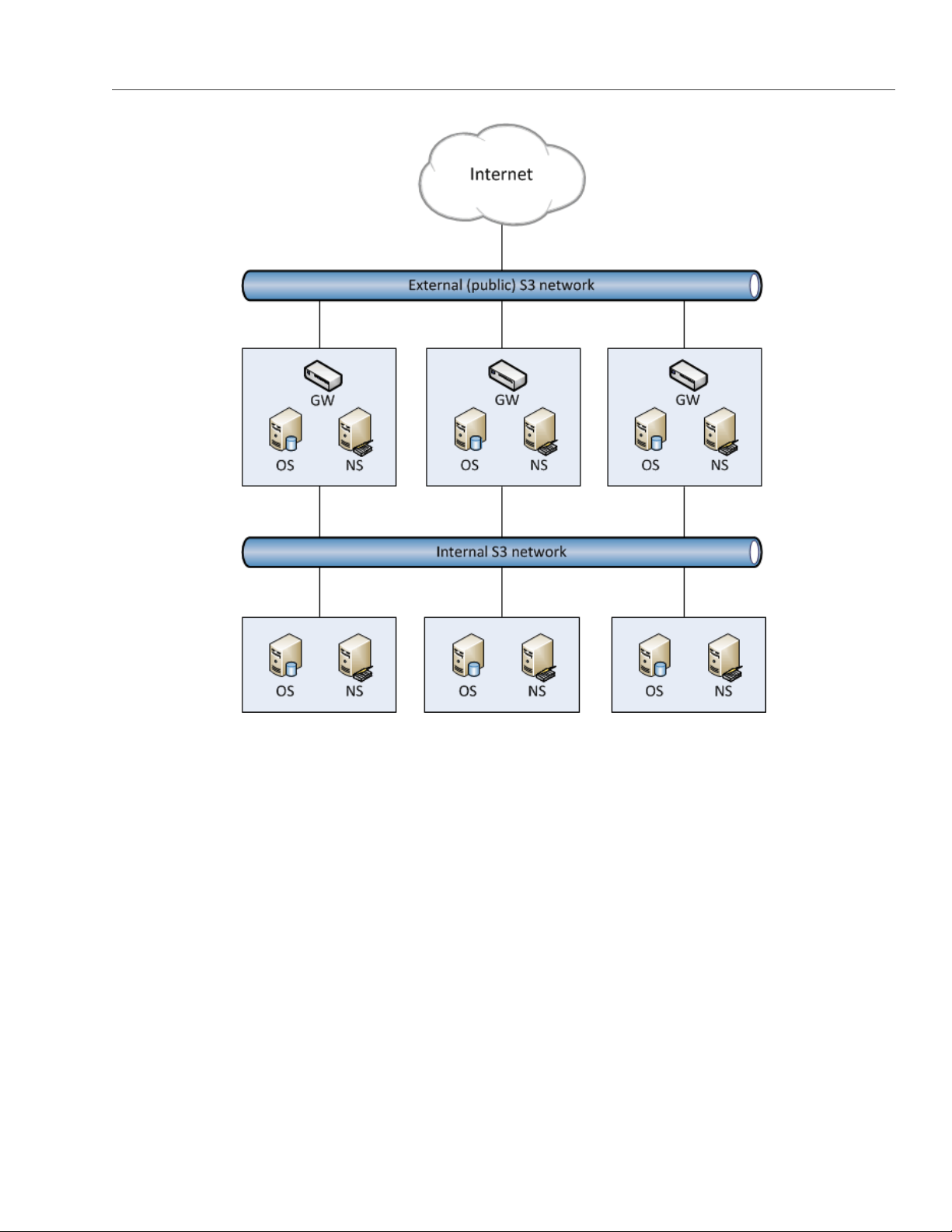
3.2 Deploying Object Storage
This chapter describes deploying object storage on top of a ready Acronis Storage cluster. As a result you will
create a setup like shown on the figure. Note that not all cluster nodes have to run object storage services.
The choice should be based on workload and hardware configurations.
24
Page 30
3.2. Deploying Object Storage
To set up object storage services, do the following:
1. Plan the S3 network. Like a Acronis Storage cluster, an object storage cluster needs two networks:
• An internal network in which NS, OS, and GW will interact. These services will generate traffic similar
in amount to the total (incoming and outgoing) S3 user traffic. If this is not going to be much, it is
reasonable to use the same internal network for both object storage and Acronis Storage. If, how-
ever, you expect that object storage traffic will compete with Acronis Storage traffic, it is reasonable
to have S3 traffic go through the user data network (i.e. datacenter network). Once you choose a
network for S3 traffic, you determine which IP addresses can be used while adding cluster nodes.
• An external (public) network through which end users will access the S3 storage. Standard HTTP and
HTTPS ports must be open in this network.
An object storage cluster is almost completely independent on base block storage (like all access points,
including virtual environments and iSCSI). Object and name servers keep their data in the Acronis Storage
25
Page 31

Chapter 3. Accessing Acronis Storage Clusters via S3 Protocol
cluster in the same way as virtual environments, iSCSI, and other services do. So the OS and NS services
depend on vstorage-mount (client) and can only work when the cluster is mounted. Unlike them, gateway
is a stateless service that has no data. It is thus independent on vstorage-mount and can theoretically
be run even on nodes where the Acronis Storage cluster is not mounted. However, for simplicity, we
recommend creating gateways on nodes with object and name servers.
Object and name servers also utilize the standard high availability means of Acronis Storage (i.e. the
shaman service). Like virtual environments and iSCSI, OS and NS are subscribed to HA cluster events.
However, unlike other services, S3 cluster components cannot be managed (tracked and relocated be-
tween nodes) by shaman. Instead, this is done by the S3 configuration service that is subscribed to HA
cluster events and notified by shaman whether nodes are healthy and can run services. For this reason,
S3 cluster components are not shown in shaman top output.
Gateway services which are stateless are never relocated and their high availability is not managed by
the Acronis Storage cluster. Instead, a new gateway service is created when necessary.
2. Make sure that each node that will run OS and NS services is in the high availability cluster. You can add
nodes to HA cluster with the shaman join command.
3. Install the vstorage-ostor package on each cluster node.
# yum install vstorage-ostor
4. Create a cluster configuration on one of the cluster nodes where object storage services will run. It is
recommended to create 10 NS and 10 OS services per each node. For example, if you are going to use
five nodes, you will need 50 NS and 50 OS. Run this command on the first cluster node.
# ostor-ctl create -n <IP_addr> \
-c ”vstorage://<cluster_name>/<ostor_dir> <NS_num> <OS_num>”
where
• <IP_addr> is the node’s IP address that object storage will go through,
• <cluster_name> is the name of your Acronis Storage cluster,
• <ostor_dir> is the directory in the cluster with object storage service files,
• <NS_num>, <OS_num> are the numbers of NS and OS, respectively.
You will be asked to enter and confirm a password for the new object storage (it can be the same as your
Acronis Storage cluster password). You will need this password to add new nodes.
5. Launch the configuration service.
26
Page 32

3.2. Deploying Object Storage
# systemctl start ostor-cfgd.service
# systemctl enable ostor-cfgd.service
6. Initialize new object storage on the first node. The ostor_dir directory will be created in the root of your
cluster.
# ostor-ctl init-storage -n <IP_addr> -s <cluster_mount_point>
You will need to provide the IP address and object storage password specified on step 3.
7. Add to the DNS public IP addresses of nodes that will run GW services. You can configure the DNS to
enable access to your object storage via a hostname, and to have the S3 endpoint receive virtual hosted-
style REST API requests with URIs like http://bucketname.s3.example.com/objectname.
After configuring DNS, make sure that DNS resolver for your S3 access point works from client machines.
Note: Only buckets with DNS-compatible names can be accessed with virtual hosted-style re-
quests. For more details, see Bucket and Key Naming Policies on page 36.
Below is an example of a DNS zones configuration file for the BIND DNS server:
;$Id$
$TTL 1h @ IN SOA ns.example.com. s3.example.com. (
2013052112 ; serial
1h ; refresh
30m ; retry
7d ; expiration
1h ) ; minimum
NS ns.example.com.
$ORIGIN s3.example.com
h1 IN A 10.29.1.95
A 10.29.0.142
A 10.29.0.137
* IN CNAME @
This configuration instructs the DNS to redirect all requests with URI http//.s3.example.com/ to one of the
endpoints listed in resource record h1 (10.29.1.95, 10.29.0.142 or 10.29.0.137) in a cyclic (round-robin)
manner.
8. Add nodes where object storage services will run to the configuration. To do this run the ostor-ctl add-host
27
Page 33

Chapter 3. Accessing Acronis Storage Clusters via S3 Protocol
command on every such node:
# ostor-ctl add-host -H <internal_IP_address> -r <cluster_mount_point>/<ostor_dir>
This command will automatically detect and use the node’s hostname and have the object storage agent
service listen on an internal IP address. You will need to provide the object storage password set on step
3.
9. Create S3 gateway instances on chosen nodes with Internet access and external IP addresses.
Note: For security reasons, make sure that only nginx can access the external network and that S3
gateways only listen on internal IP addresses.
# ostor-ctl add-s3gw -a <internal_IP_address>
where <internal_IP_address> is the internal IP address of the node with the gateway.
Note: Port number is mandatory.
10. Launch object storage agent on each cluster node added to the object storage configuration.
# systemctl start ostor-agentd
# systemctl enable ostor-agentd
11. Make sure NS and OS services are bound to the nodes.
By default agents will try to assign NS and OS services to the nodes automatically in a round-robin man-
ner. However, manual assignment is required if a new host has been added to the configuration, or if
the current configuration is not optimized (for details, see Manually Binding Services to Nodes on page 30.
You can check the current binding configuration with the ostor-ctl agent-status command. For example:
# ostor-ctl agent-status
TYPE SVC_ID STATUS UPTIME HOST_ID ADDRS
S3GW 8000000000000009 ACTIVE 527 fcbf5602197245da 127.0.0.1:9090
S3GW 8000000000000008 ACTIVE 536 4f0038db65274507 127.0.0.1:9090
28
S3GW 8000000000000007 ACTIVE 572 958e982fcc794e58 127.0.0.1:9090
OS 1000000000000005 ACTIVE 452 4f0038db65274507 10.30.29.124:39746
OS 1000000000000004 ACTIVE 647 fcbf5602197245da 10.30.27.69:56363
Page 34

3.2. Deploying Object Storage
OS 1000000000000003 ACTIVE 452 4f0038db65274507 10.30.29.124:52831
NS 0800000000000002 ACTIVE 647 fcbf5602197245da 10.30.27.69:56463
NS 0800000000000001 ACTIVE 452 4f0038db65274507 10.30.29.124:53044
NS 0800000000000000 ACTIVE 647 fcbf5602197245da 10.30.27.69:37876
12. Install one nginx Web server per each S3 endpoint you need. On nodes where you install nginx, replace the
contents of its configuration file /etc/nginx/conf.d/nginx.conf with the following (replace the IP addresses as
required):
upstream s3 {
server 127.0.0.1:9000; #S3 gateway 1 internal IP address
server 127.0.0.2:9000; #S3 gateway 2 internal IP address
server 127.0.0.3:9000; #S3 gateway 3 internal IP address
# Optional load balancing parameters (see
# http://nginx.org/en/docs/http/load_balancing.html)
}
server {
listen 80;
server_name 172.0.0.1; #S3 endpoint. If you have DNS configured,
#replace the IP address with the corresponding hostname.
client_max_body_size 5g;
#charset koi8-r;
#access_log /var/log/nginx/log/host.access.log main;
location / {
fastcgi_pass_header Connection-close;
fastcgi_pass s3;
fastcgi_no_cache 1;
include fastcgi_params;
fastcgi_request_buffering off;
fastcgi_max_temp_file_size 0;
}
13. Launch nginx:
# systemctl start nginx.service
# systemctl enable nginx.service
The object storage is deployed. Now you can add S3 users with the ostor-s3-admin tool. For example:
29
Page 35

Chapter 3. Accessing Acronis Storage Clusters via S3 Protocol
# ostor-s3-admin create-user -e user@email.com
Created user: email=user@email.com,user id=81d406fa613ad6c1
Key pair[0]: access key id=81d406fa613ad6c1S8HL,
secret access key=ya8iq3yrEYEhpErCkSmui6ifBghDDLdN2vso3sJn
The access key ID and secret access key pair, along with S3 endpoint, are required to connect to object storage
from a client application.
To check that installation has been successful or just monitor object storage status, use the ostor-ctl get-config
command. For example:
# ostor-ctl get-config
07-08-15 11:58:45.470 Use configuration service ’ostor’
SVC_ID TYPE URI
8000000000000006 S3GW svc://1039c0dc90d64607/?address=127.0.0.1:9000
0800000000000000 NS vstorage://cluster1/ostor/services/0800000000000000
1000000000000001 OS vstorage://cluster1/ostor/services/1000000000000001
1000000000000002 OS vstorage://cluster1/ostor/services/1000000000000002
1000000000000003 OS vstorage://cluster1/ostor/services/1000000000000003
1000000000000004 OS vstorage://cluster1/ostor/services/1000000000000004
8000000000000009 S3GW svc://7a1789d20d9f4490/?address=127.0.0.1:9000
800000000000000c S3GW svc://7a1789d20d9f4490/?address=127.0.0.1:9090
3.2.1 Manually Binding Services to Nodes
You can manually bind services to nodes with the ostor-ctl bind command. You will need to specify the target
node ID and one or more service IDs to bind to it. For example, the command:
# ostor-ctl bind -H 4f0038db65274507 -S 0800000000000001 \
-S 1000000000000003 -S 1000000000000005
binds services with IDs 800000000000001, 1000000000000003, and 1000000000000005 to a host with ID 4f0038db65274507.
A service can only be bound to a host that is connected to the shared storage which stores that service’s data.
That is, the cluster name in service URI must match the cluster name in host URI.
For example, in a configuration with two shared storages stor1 and stor2 (see below) services with URIs start-
ing with vstorage://stor1 can only be bound to hosts host510 and host511 while services with URIs starting with
vstorage://stor2 can only be bound to hosts host512 and host513.
30
Page 36

3.3. Managing S3 Users
# ostor-ctl get-config
SVC_ID TYPE URI
0800000000000000 NS vstorage://stor1/s3-data/services/0800000000000000
0800000000000001 NS vstorage://stor1/s3-data/services/0800000000000001
0800000000000002 NS vstorage://stor2/s3-data/services/0800000000000002
1000000000000003 OS vstorage://stor1/s3-data/services/1000000000000003
1000000000000004 OS vstorage://stor2/s3-data/services/1000000000000004
1000000000000005 OS vstorage://stor1/s3-data/services/1000000000000005
HOST_ID HOSTNAME URI
0fcbf5602197245da host510:2530 vstorage://stor1/s3-data
4f0038db65274507 host511:2530 vstorage://stor1/s3-data
958e982fcc794e58 host512:2530 vstorage://stor2/s3-data
953e976abc773451 host513:2530 vstorage://stor2/s3-data
3.3 Managing S3 Users
The concept of S3 user is one of the base concepts of object storage along with those of object and bucket (con-
tainer for storing objects). Amazon S3 protocol uses permissions model based on access control lists (ACLs)
where each bucket and each object is assigned an ACL that lists all users with access to the given resource
and the type of this access (read, write, read ACL, write ACL). The list of users includes entity owner assigned
to every object and bucket at creation. Entity owner has extra rights compared to other users, for example,
bucket owner is the only one who can delete that bucket.
User model and access policies implemented in Acronis Object Storage comply with the Amazon S3 user model
and access policies.
User management scenarios in Acronis Object Storage are largely based on the Amazon Web Services user
management and include the following operations: create, query, delete users as well as generate, revoke
user access key pairs.
3.3.1 Creating S3 Users
You can generate a unique random S3 user ID and an access key pair (S3 Access Key ID, S3 Secret Access Key)
using the ostor-s3-admin create-user command. You need to specify a user email. For example:
31
Page 37

Chapter 3. Accessing Acronis Storage Clusters via S3 Protocol
# ostor-s3-admin create-user -e user@email.com
UserEmail:user@email.com
UserId:a49e12a226bd760f
KeyPair[0]:S3AccessKeyId:a49e12a226bd760fGHQ7
KeyPair[0]:S3SecretAccessKey:HSDu2DA00JNGjnRcAhLKfhrvlymzOVdLPsCK2dcq
Flags:none
S3 user ID is a 16-digit hexadecimal string. The generated access key pair is used to sign requests to the S3
object storage according to the Amazon S3 Signature Version 2 authentication scheme.
3.3.2 Listing S3 Users
You can list all object storage users with the ostor-s3-admin query-users command. Information for each user can
take one or more sequential rows in the table. Additional rows are used to lists S3 access key pairs associated
with the user. If the user does not have any active key pairs, minus signs are shown in the corresponding table
cells. For example:
# ostor-s3-admin query-users
S3 USER ID S3 ACCESS KEY ID S3 SECRET ACCESS KEY S3 USER EMAIL
bf0b3b15eb7c9019 bf0b3b15eb7c9019I36Y *** user2@abc.com
d866d9d114cc3d20 d866d9d114cc3d20G456 *** user1@abc.com
d866d9d114cc3d20D8EW ***
e86d1c19e616455 - - user3@abc.com
To output the list in XML, use the -X option; to output secret keys, use the -a option. For example:
# ostor-s3-admin query-users -a -X
<?xml version=”1.0” encoding=”UTF-8”?><QueryUsersResult><Users><User><Id>a49e12a226bd760f</Id><Ema
il>user@email.com</Email><Keys><OwnerId>0000000000000000</OwnerId><KeyPair><S3AccessKeyId>a49e12a2
26bd760fGHQ7</S3AccessKeyId><S3SecretAccessKey>HSDu2DA00JNGjnRcAhLKfhrvlymzOVdLPsCK2dcq</S3SecretA
ccessKey></KeyPair></Keys></User><User><Id>d7c53fc1f931661f</Id><Email>user@email.com</Email><Keys
><OwnerId>0000000000000000</OwnerId><KeyPair><S3AccessKeyId>d7c53fc1f931661fZLIV</S3AccessKeyId><S
3SecretAccessKey>JL7gt1OH873zR0Fzv8Oh9ZuA6JtCVnkgV7lET6ET</S3SecretAccessKey></KeyPair></Keys></Us
er></Users></QueryUsersResult>
32
Page 38

3.3. Managing S3 Users
3.3.3 Querying S3 User Information
To display information about the specified user, use the ostor-s3-admin query-user-info command. You need to
specify either the user email (-e) or S3 ID (-i). For example:
# ostor-s3-admin query-user-info -e user@email.com
Query user: user id=d866d9d114cc3d20, user email=user@email.com
Key pair[0]: access key id=d866d9d114cc3d20G456,
secret access key=5EAne6PLL1jxprouRqq8hmfONMfgrJcOwbowCoTt
Key pair[1]: access key id=d866d9d114cc3d20D8EW,
secret access key=83tTsNAuuRyoBBqhxMFqHAC60dhKHtTCCkQe54zu
3.3.4 Disabling S3 Users
You can disable a user with the ostor-s3-admin disable-user command. You need to specify either the user email
(-e) or S3 ID (-i). For example:
# ostor-s3-admin disable-user -e user@email.com
3.3.5 Deleting S3 Users
You can delete existing object storage users with the ostor-s3-admin delete-user command. Users who own any
buckets cannot be deleted, so delete user’s buckets first. You need to specify either the user email (-e) or S3
ID (-i). For example:
# ostor-s3-admin delete-user -i bf0b3b15eb7c9019
Deleted user: user id=bf0b3b15eb7c9019
3.3.6 Generating S3 User Access Key Pairs
You can generate a new access key pair for the specified user with the ostor-s3-admin gen-access-key command.
The maximum of 2 active access key pairs are allowed per user (same as with the Amazon Web Services). You
need to specify either the user email (-e) or S3 ID (-i). For example:
# ostor-s3-admin gen-access-key -e user@email.com
Generate access key: user id=d866d9d114cc3d20, access key id=d866d9d114cc3d20D8EW,
33
Page 39

Chapter 3. Accessing Acronis Storage Clusters via S3 Protocol
secret access key=83tTsNAuuRyoBBqhxMFqHAC60dhKHtTCCkQe54zu
Note: It is recommended to periodically revoke old and generate new access key pairs.
3.3.7 Revoking S3 User Access Key Pairs
You can revoke the specified access key pair of the specified user with the ostor-s3-admin revoke-access-key com-
mand. You need to specify the access key in the key pair you want to delete as well as the user email or S3 ID.
For example:
# ostor-s3-admin revoke-access-key -e user@email.com -k de86d1c19e616455YIPU
Revoke access key: user id=de86d1c19e616455, access key id=de86d1c19e616455YIPU
Note: It is recommended to periodically revoke old and generate new access key pairs.
3.4 Managing Object Storage Buckets
All objects in Amazon S3-like storage are stored in containers named buckets. Buckets are addressed by names
that are unique in the given object storage, so an S3 user of that object storage cannot create a bucket that
has the same name as a different bucket in the same object storage. Buckets are used to:
• group and isolate objects from those in other buckets,
• provide ACL management mechanisms for objects in them,
• set per-bucket access policies, for example, versioning in the bucket.
You can manage buckets with the ostor-s3-admin tool as well as S3 API third-party S3 browsers like CyberDuck or
DragonDisk.
Note: As ostor-s3-admin commands are assumed to be issued by object storage administrators, they do
not include any authentication or authorization checks.
34
Page 40

3.4. Managing Object Storage Buckets
3.4.1 Listing Bucket Contents
You can list bucket contents with a web browser. To do this, visit the URL that consists of the external DNS
name for the S3 endpoint that you specified when creating the S3 cluster and the bucket name. For example,
mys3storage.example.com/mybucket.
Note: You can also copy the link to bucket contents by right-clicking it in CyberDuck, and then selecting
Copy URL.
3.4.1.1 Managing Buckets from Command Line
3.4.2 Listing Object Storage Buckets
You can list all buckets in the S3 object storage with the ostor-s3-admin -c list-all-buckets command. For each
bucket, the command shows owner, creation data, versioning status, and total size (the size of all objects
stored in the bucket plus the size of all unfinished multipart uploads for this bucket). For example:
# ostor-s3-admin -c list-all-buckets
Total 3 buckets
BUCKET OWNER CREATION_DATE VERSIONING TOTAL SIZE, BYTES
bucket1 968d1a79968d1a79 2015-08-18T09:32:35.000Z none 1024
bucket2 968d1a79968d1a79 2015-08-18T09:18:20.000Z enabled 0
bucket3 968d1a79968d1a79 2015-08-18T09:22:15.000Z suspended 1024000
3.4.3 Querying Object Storage Bucket Information
You can query bucket metadata information and ACL with the ostor-s3-admin -c query-bucket-info command. For
example, for bucket1:
# ostor-s3-admin -c query-bucket-info -b bucket1
BUCKET OWNER CREATION_DATE VERSIONING TOTAL SIZE, BYTES
bucket1 968d1a79968d1a79 2015-08-18T09:32:35.000Z none 1024
BUCKET ACL GROUP GRANT READ WRITE READ_ACP WRITE_ACP S3 USER GRANT READ WRITE READ_ACP WRITE_ACP
968d1a79968d1a79 - - - - abcdabcdabcdabcd + + + +
35
Page 41

Chapter 3. Accessing Acronis Storage Clusters via S3 Protocol
3.4.4 Changing Object Storage Bucket Owners
You can pass ownership of a bucket to the specified user with the ostor-s3-admin -c change-bucket-owner command.
For example, to make user with ID bf0b3b15eb7c9019 the owner of bucket1:
# ostor-s3-admin -c change-bucket-owner -b bucket1 -i bf0b3b15eb7c9019
Changed owner of the bucket bucket1. New owner bf0b3b15eb7c9019
3.4.5 Deleting Object Storage Buckets
You can delete the specified bucket with the ostor-s3-admin -c delete-bucket command. Deleting a bucket will
delete all objects in it (including their old versions) as well as all unfinished multipart uploads for this bucket
For example:
# ostor-s3-admin -c delete-bucket -b bucket1
Deleted bucket bucket1
3.5 Best Practices for Using Object Storage
This chapter describes recommendations on using various features of Acronis Object Storage. These recom-
mendations are called to help you enable additional functionality or improve convenience or performance of
Acronis Object Storage.
3.5.1 Bucket and Key Naming Policies
It is recommended to use bucket names that comply with DNS naming conventions:
• can be from 3 to 63 characters long,
• must start and end with a lowercase letter or number,
• can contain lowercase letters, numbers, periods (.), hyphens (-), and underscores (_),
• can be a series of valid name parts (described previously) separated by periods.
An object key can be a string of any UTF-8 encoded characters up to 1024 bytes long.
36
Page 42

3.6. Appendices
3.5.2 Improving Performance of PUT Operations
Object storage supports uploading of objects as large as 5 GB in size with a single PUT request. Upload per-
formance can be improved, however, by splitting large objects into pieces and uploading them concurrently
with multipart upload API. This approach will divide the load between multiple OS services.
It is recommended to use multipart uploads for objects larger than 5 MB.
3.6 Appendices
This chapter provides reference information related to Acronis Object Storage.
3.6.1 Appendix A: Supported Amazon S3 REST Operations
The following Amazon S3 REST operations are currently supported by the Acronis Storage implementation of
the Amazon S3 protocol:
Service operations:
• GET Service
Bucket operations:
• DELETE Bucket
• GET Bucket (List Objects)
• GET Bucket acl
• GET Bucket location
• GET Bucket Object versions
• GET Bucket versioning
• HEAD Bucket
• List Multipart Uploads
• PUT Bucket
• PUT Bucket acl
37
Page 43

• PUT Bucket versioning
Object operations:
• DELETE Object
• DELETE Multiple Objects
• GET Object
• GET Object ACL
• HEAD Object
• POST Object
• PUT Object
• PUT Object - Copy
• PUT Object acl
Chapter 3. Accessing Acronis Storage Clusters via S3 Protocol
• Initiate Multipart Upload
• Upload Part
• Complete Multipart Upload
• Abort Multipart Upload
• List Parts
Note: For a complete list of Amazon S3 REST operations, see Amazon S3 REST API documentation.
3.6.2 Appendix B: Supported Amazon Request Headers
The following Amazon S3 REST request headers are currently supported by the Acronis Storage implementa-
tion of the Amazon S3 protocol:
• x-amz-acl
• x-amz-delete-marker
• x-amz-grant-full-control
38
Page 44

3.6. Appendices
• x-amz-grant-read-acp
• x-amz-grant-read
• x-amz-grant-write
• x-amz-grant-write-acp
• x-amz-meta-**
• x-amz-version-id
• x-amz-copy-source
• x-amz-metadata-directive
• x-amz-copy-source-version-id
3.6.3 Appendix C: Supported Authentication Schemes
The following authentication scheme is supported by the Acronis Storage implementation of the Amazon S3
protocol:
• Signature Version 2.
• Signature Version 4.
39
Page 45

CHAPTER 4
Monitoring Acronis Storage Clusters
Monitoring a Acronis Storage cluster is very important because it allows you to check the status and health of
all computers in the cluster and react as necessary. This chapter explains how to monitor your Acronis Storage
cluster.
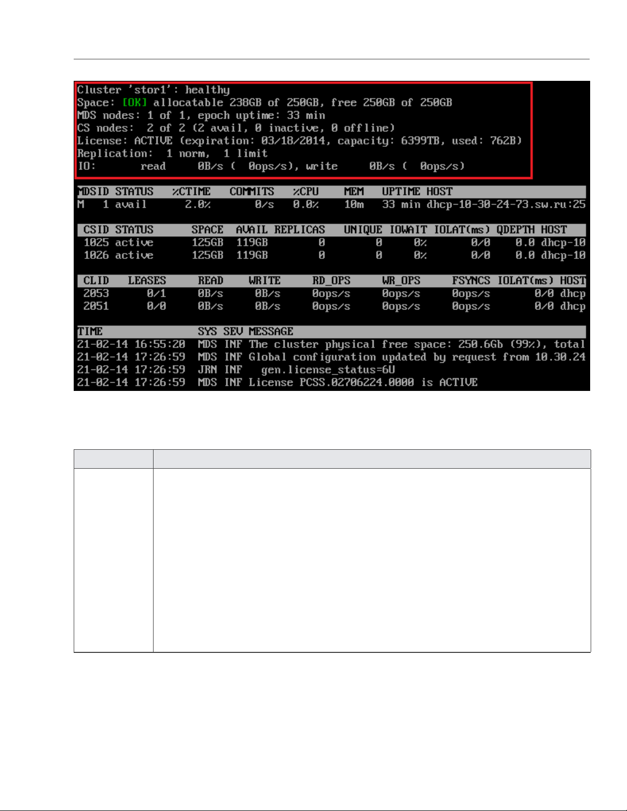
4.1 Monitoring General Cluster Parameters
By monitoring general parameters, you can get detailed information about all components of a Acronis Storage
cluster, its overall status and health. To display this information, use the vstorage -c <cluster_name> top command,
for example:
40
Page 46
4.1. Monitoring General Cluster Parameters
The command above shows detailed information about the stor1 cluster. The general parameters (highlighted
in red) are explained in the table below.
Parameter Description
Cluster Overall status of the cluster:
• healthy. All chunk servers in the cluster are active.
• unknown. There is not enough information about the cluster state (e.g., because the
master MDS server was elected a while ago).
• degraded. Some of the chunk servers in the cluster are inactive.
• failure. The cluster has too many inactive chunk servers; the automatic replication is
disabled.
• SMART warning. One or more physical disks attached to cluster Nodes are in pre-
failure condition. For details, see Monitoring Physical Disks on page 52
41
Page 47

Chapter 4. Monitoring Acronis Storage Clusters
Parameter Description
Space Amount of disk space in the cluster:
• free. Free physical disk space in the cluster.
• allocatable. Amount of logical disk space available to clients. Allocatable disk space is
calculated on the basis of the current replication parameters and free disk space on
chunk servers. It may also be limited by license.
Note: For more information on monitoring and understanding disk space usage in
clusters, see Understanding Disk Space Usage on page 45
MDS nodes Number of active MDS servers as compared to the total number of MDS servers configured
for the cluster.
epoch time Time elapsed since the MDS master server election.
CS nodes Number of active chunk servers as compared to the total number of chunk servers config-
ured for the cluster.
The information in parentheses informs you of the number of
• Active chunk servers (avail.) that are currently up and running in the cluster.
• Inactive chunk servers (inactive) that are temporarily unavailable. A chunk server is
marked as inactive during its first 5 minutes of inactivity.
• Offline chunk servers (offline) that have been inactive for more than 5 minutes. A
chunk server changes its state to offline after 5 minutes of inactivity. Once the state
is changed to offline, the cluster starts replicating data to restore the chunks that were
stored on the offline chunk server.
License Key number under which the license is registered on the Key Authentication server and
license state.
Replication Replication settings. The normal number of chunk replicas and the limit after which a chunk
gets blocked until recovered.
IO Disks IO activity in the cluster:
• Speed of read and write I/O operations, in bytes per second.
• Number of read and write I/O operations per second.
42
Page 48

4.2. Monitoring Metadata Servers
4.2 Monitoring Metadata Servers
MDS servers are a critical component of any Acronis Storage cluster, and monitoring the health and state of
MDS servers is a very critical task. To monitor MDS servers, use the vstorage -c <cluster_name> top command, for
example:
The command above shows detailed information about the stor1 cluster. The monitoring parameters for MDS
servers (highlighted in red) are explained in the table below:
Parameter Description
MDSID MDS server identifier (ID).
The letter “M” before ID, if present, means that the given server is the master
MDS server.
STATUS MDS server status.
%CTIME Total time the MDS server spent writing to the local journal.
COMMITS Local journal commit rate.
%CPU MDS server activity time.
MEM Amount of physical memory the MDS server uses.
43
Page 49

Chapter 4. Monitoring Acronis Storage Clusters
Parameter Description
UPTIME Time elapsed since the last MDS server start.
HOST MDS server hostname or IP address.
4.3 Monitoring Chunk Servers
By monitoring chunk servers, you can keep track of the disk space available in a Acronis Storage cluster. To
monitor chunk servers, use the vstorage -c <cluster_name> top command, for example:
The command above shows detailed information about the stor1 cluster. The monitoring parameters for chunk
servers (highlighted in red) are explained in the table below:
Parameter Description
CSID Chunk server identifier (ID).
44
Page 50

4.3. Monitoring Chunk Servers
Parameter Description
STATUS Chunk server status:
• active. The chunk server is up and running.
• Inactive. The chunk server is temporarily unavailable. A chunk server is marked as inac-
tive during its first 5 minutes of inactivity.
• offline. The chunk server is inactive for more than 5 minutes. After the chunk server
goes offline, the cluster starts replicating data to restore the chunks that were stored on
the affected chunk server.
• dropped. The chunk serve was removed by the administrator.
SPACE Total amount of disk space on the chunk server.
FREE Free disk space on the chunk server.
REPLICAS Number of replicas stored on the chunk server.
IOWAIT Percentage of time spent waiting for I/O operations being served.
IOLAT Average/maximum time, in milliseconds, the client needed to complete a single IO operation
during the last 20 seconds.
QDEPTH Average chunk server I/O queue depth.
HOST Chunk server hostname or IP address.
FLAGS The following flags may be shown for active chunk servers:
• J: The CS uses a write journal.
• C: Checksumming is enabled for the CS. Checksumming lets you know when a third party
changes the data on the disk.
• D: Direct I/O, the normal state for a CS without a write journal.
• c: The chunk server’s write journal is clean, there is nothing to commit from the write
journaling SSD to the HDD where the CS is located.
4.3.1 Understanding Disk Space Usage
Usually, you get the information on how disk space is used in your cluster with the vstorage top command. This
command displays the following disk-related information: total space, free space, and allocatable space. For
example:
45
Page 51
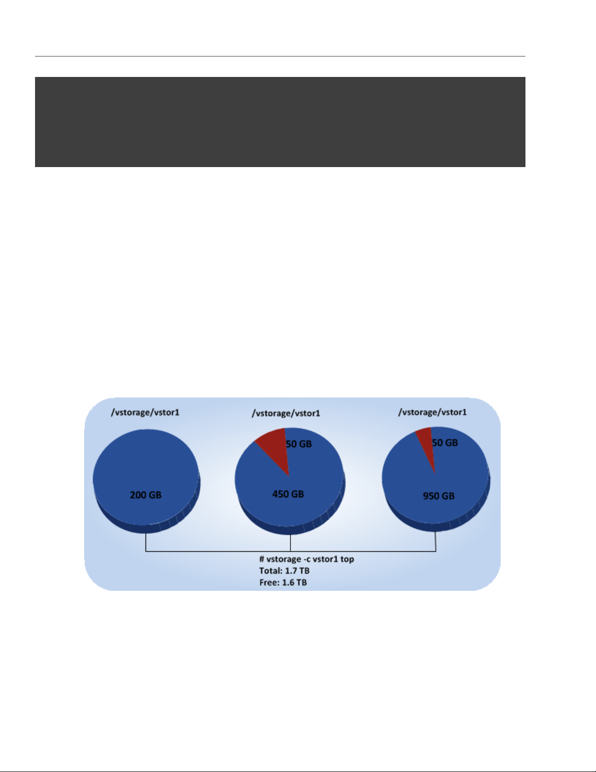
Chapter 4. Monitoring Acronis Storage Clusters
# vstorage -c stor1 top
connected to MDS#1
Cluster ’stor1’: healthy
Space: [OK] allocatable 180GB of 200GB, free 1.6TB of 1.7TB
...
In this command output:
• 1.7TB is the total disk space in the stor1 cluster. The total disk space is calculated on the basis of used and
free disk space on all partitions in the cluster. Used disk space includes the space occupied by all data
chunks and their replicas plus the space occupied by any other files stored on the cluster partitions.
Let us assume that you have a 100 GB partition and 20 GB on this partition are occupied by some files.
Now if you set up a chunk server on this partition, this will add 100 GB to the total disk space of the
cluster, though only 80 GB of this disk space will be free and available for storing data chunks.
• 1.6TB is the free disk space in the stor1 cluster. Free disk space is calculated by subtracting the disk space
occupied by data chunks and any other files on the cluster partitions from the total disk space.
For example, if the amount of free disk space is 1.6 TB and the total disk space is 1.7 TB, this means that
about 100 GB on the cluster partitions are already occupied by some files.
• allocatable 180GB of 200GB is the amount of free disk space that can used for storing data chunks. See
Understanding allocatable disk space below for details.
46
Page 52

4.3. Monitoring Chunk Servers
4.3.1.1 Understanding Allocatable Disk Space
When monitoring disk space information in the cluster, you also need to pay attention to the space reported
by the vstorage top utility as allocatable. Allocatable space is the amount of disk space that is free and can be
used for storing user data. Once this space runs out, no data can be written to the cluster.
To better understand how allocatable disk space is calculated, let us consider the following example:
• The cluster has 3 chunk servers. The first chunk server has 200 GB of disk space, the second one — 500
GB, and the third one — 1 TB.
• The default replication factor of 3 is used in the cluster, meaning that each data chunk must have 3
replicas stored on three different chunk servers.
In this example, the available disk space will equal 200 GB, that is, set to the amount of disk space on the
smallest chunk server:
# vstorage -c stor1 top
connected to MDS#1
Cluster ’stor1’: healthy
Space: [OK] allocatable 180GB of 200GB, free 1.6TB of 1.7TB
...
This is explained by the fact that in this cluster configuration each server is set to store one replica for each
47
Page 53

Chapter 4. Monitoring Acronis Storage Clusters
data chunk. So once the disk space on the smallest chunk server (200 GB) runs out, no more chunks in the
cluster can be created until a new chunk server is added or the replication factor is decreased.
If you now change the replication factor to 2, the vstorage top command will report the available disk space as
700 GB:
# vstorage set-attr -R /vstorage/stor1 replicas=2:1
# vstorage -c stor1 top
connected to MDS#1
Cluster ’stor1’: healthy
Space: [OK] allocatable 680GB of 700GB, free 1.6TB of 1.7TB
...
The available disk space has increased because now only 2 replicas are created for each data chunk and new
chunks can be made even if the smallest chunk server runs out of space (in this case, replicas will be stored
on a bigger chunk server).
Note: Allocatable disk space may also be limited by license.
4.3.1.2 Viewing Space Occupied by Data Chunks
To view the total amount of disk space occupied by all user data in the cluster, run the vstorage top command
and press the V key on your keyboard. Once you do this, your command output should look like the following:
# vstorage -c stor1 top
Cluster ’stor1’: healthy
Space: [OK] allocatable 180GB of 200GB, free 1.6TB of 1.7TB
MDS nodes: 1 of 1, epoch uptime: 2d 4h
CS nodes: 3 of 3 (3 avail, 0 inactive, 0 offline)
Replication: 2 norm, 1 limit, 4 max
Chunks: [OK] 38 (100%) healthy, 0 (0%) degraded, 0 (0%) urgent,
0 (0%) blocked, 0 (0%) offline, 0 (0%) replicating,
0 (0%) overcommitted, 0 (0%) deleting, 0 (0%) void
FS: 1GB in 51 files, 51 inodes, 23 file maps, 38 chunks, 76 chunk replicas
...
48
Page 54

4.3. Monitoring Chunk Servers
Note: The FS field shows the size of all user data in the cluster without consideration for replicas.
4.3.2 Exploring Chunk States
The table below lists all possible states a chunk can have.
Status Description
healthy Percentage of chunks that have enough active replicas. The normal state of
chunks.
replicating Percentage of chunks which are being replicated. Write operations on such chunks
are frozen until replication ends.
offline Percentage of chunks all replicas of which are offline. Such chunks are completely
inaccessible for the cluster and cannot be replicated, read from or written to. All
requests to an offline chunk are frozen until a CS that stores that chunk’s replica
goes online.
Get offline chunk servers back online as fast as possible to avoid losing data.
void Percentage of chunks that have been allocated but never used yet. Such chunks
contain no data. It is normal to have some void chunks in the cluster.
pending Percentage of chunks that must be replicated immediately. For a write request
from client to a chunk to complete, the chunk must have at least the set minimum
amount of replicas. If it does not, the chunk is blocked and the write request can-
not be completed. As blocked chunks must be replicated as soon as possible, the
cluster places them in a special high-priority replication queue and reports them
as pending.
blocked Percentage of chunks which have fewer active replicas than the set minimum
amount. Write requests to a blocked chunk are frozen until it has at least the
set minimum amount of replicas. Read requests to blocked chunks are allowed,
however, as they still have some active replicas left. Blocked chunks have higher
replication priority than degraded chunks.
Having blocked chunks in the cluster increases the risk of losing data, so postpone
any maintenance on working cluster nodes and get offline chunk servers back on-
line as fast as possible.
49
Page 55

Chapter 4. Monitoring Acronis Storage Clusters
Status Description
degraded Percentage of chunks with the number of active replicas lower than normal but
equal to or higher than the set minimum. Such chunks can be read from and
written to. However, in the latter case a degraded chunk becomes urgent.
urgent Percentage of chunks which are degraded and have non-identical replicas. Repli-
cas of a degraded chunk may become non-identical if some of them are not ac-
cessible during a write operation. As a result, some replicas happen to have the
new data while some still have the old data. The latter are dropped by the cluster
as fast as possible. Urgent chunks do not affect information integrity as the actual
data is stored in at least the set minimum amount of replicas.
standby Percentage of chunks that have one or more replicas in the standby state. A replica
is marked standby if it has been inactive for no more than 5 minutes.
overcommitted Percentage of chunks that have more replicas than normal. Usually these chunks
appear after the normal number of replicas has been lowered or a lot of data has
been deleted. Extra replicas are eventually dropped, however, this process may
slow down during replication.
4.4 Monitoring Clients
By monitoring clients, you can check the status and health of servers that you use to access virtual machines
and Containers. To monitor clients, use the vstorage -c <cluster_name> top command, for example:
50
Page 56
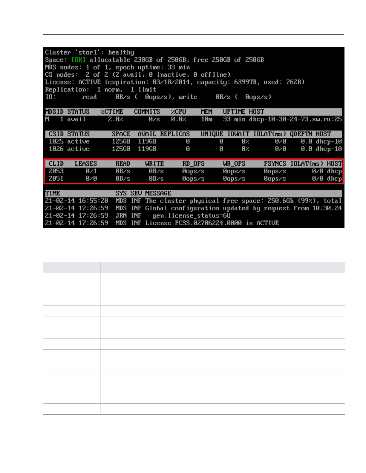
4.4. Monitoring Clients
The command above shows detailed information about the stor1 cluster. The monitoring parameters for clients
(highlighted in red) are explained in the table below:
Parameter Description
CLID Client identifier (ID).
LEASES Average number of files opened for reading/writing by the client and not yet closed,
for the last 20 seconds.
READ Average rate, in bytes per second, at which the client reads data, for the last 20 seconds.
WRITE Average rate, in bytes per second, at which the client writes data, for the last 20 sec-
onds.
RD_OPS Average number of read operations per second the client made, for the last 20 seconds.
WR_OPS Average number of write operations per second the client made, for the last 20 sec-
onds.
FSYNCS Average number of sync operations per second the client made, for the last 20 seconds.
IOLAT Average/maximum time, in milliseconds, the client needed to complete a single IO op-
eration, for the last 20 seconds.
HOST Client hostname or IP address.
51
Page 57

Chapter 4. Monitoring Acronis Storage Clusters
4.5 Monitoring Physical Disks
The S.M.A.R.T. status of physical disks is monitored by the smartctl tool installed along with Acronis. The tool is
run every 10 minutes as a cron job also added during Acronis installation. The smartctl tool polls all physical disks
attached to Hardware Nodes in the cluster, including caching and journaling SSDs, and reports the results to
the MDS server.
Note: For the tool to work, enable the S.M.A.R.T. functionality in Node’s BIOS.
You can view disk poll results for the last 10 minutes in the output of the vstorage top command. For example:
If the SMART warning message is shown in the main table, one of the physical disks is in pre-failure condition
according to S.M.A.R.T. Press d to switch to the disks table to see more details. For example:
52
Page 58
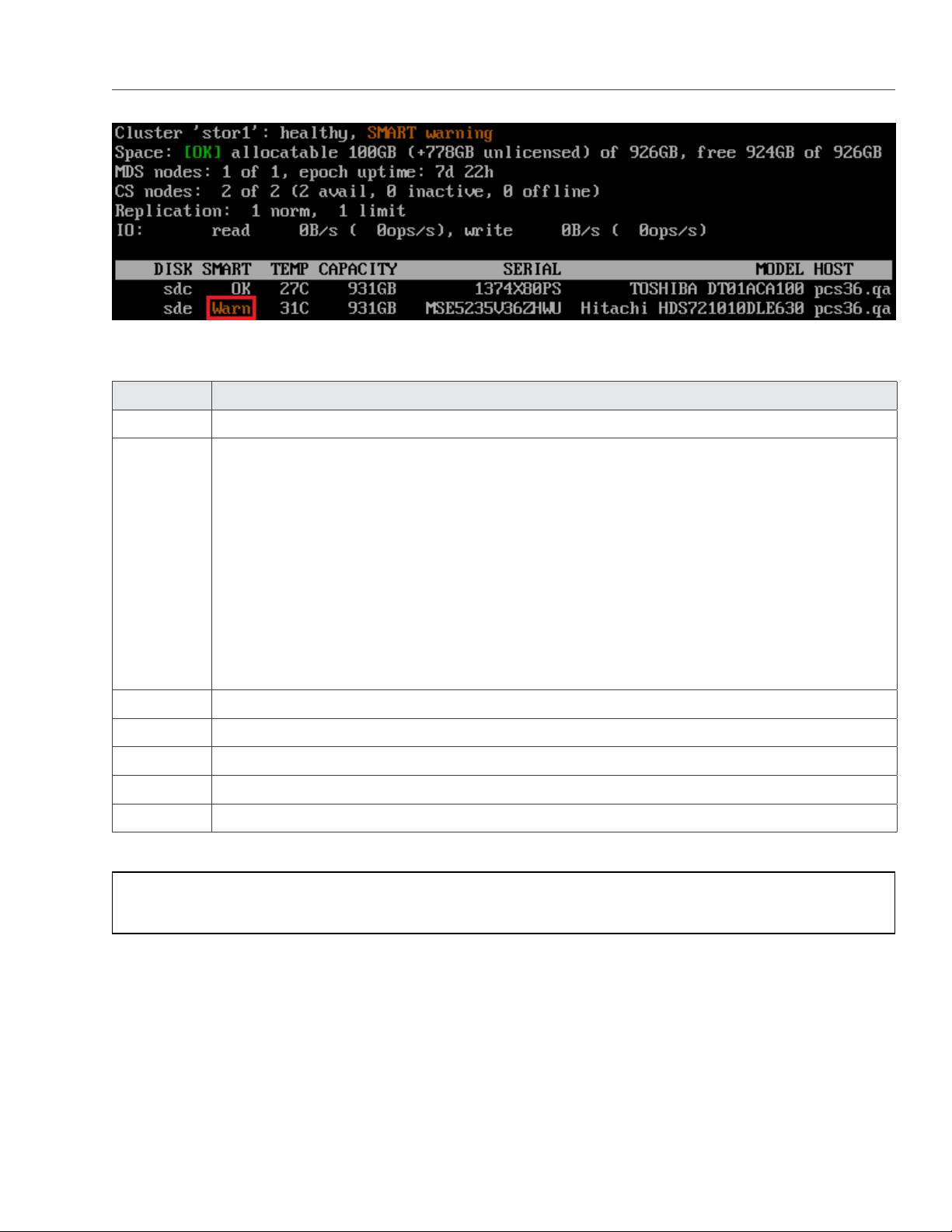
4.6. Monitoring Event Logs
The disks table shows the following parameters:
Parameter Description
DISK Disk name assigned by operating system.
SMART Disk’s S.M.A.R.T. status:
• OK: The disk is healthy.
• Warn: The disk is in pre-failure condition.
Pre-failure condition means that at least one of these S.M.A.R.T. counters is nonzero:
• Reallocated Sector Count
• Reallocated Event Count
• Current Pending Sector Count
• Offline Uncorrectable
TEMP Disk temperature in Celsius.
CAPACITY Disk capacity.
SERIAL Disk serial number.
MODEL Disk model.
HOST Disk’s host address.
Note: To disable S.M.A.R.T. disk monitoring, delete the corresponding cron job.
4.6 Monitoring Event Logs
You can use the vstorage -c <cluster_name> top utility to monitor significant events happening in a Acronis Storage
cluster, for example:
53
Page 59

Chapter 4. Monitoring Acronis Storage Clusters
The command above shows the latest events in the stor1 cluster. The information on events (highlighted in
red) is given in the table with the following columns:
Column Description
TIME Time when the event happened.
SYS Component of the cluster where the event happened (e.g., MDS for an MDS server or
JRN for local journal).
SEV Event severity.
MESSAGE Event description.
4.6.1 Exploring Basic Events
The table below describes the basic events displayed when you run the vstorage top utility.
54
Page 60

4.6. Monitoring Event Logs
Event Severity Description
MDS#<N> (<addr>:<port>) lags
behind for more than 1000
rounds
MDS#<N> (<addr>:<port>)
didn’t accept commits for M sec
MDS#<N> (<addr>:<port>) state
is outdated and will do a full
resync
JRN err Generated by the MDS master server when it detects
that MDS#<N> is stale.
This message may indicate that some MDS server is
very slow and lags behind.
JRN err Generated by the MDS master server if MDS#<N> did
not accept commits for M seconds. MDS#<N> gets
marked as stale.
This message may indicate that the MDS service on
MDS#<N> is experiencing a problem. The problem
may be critical and should be resolved as soon as pos-
sible.
JRN err Generated by the MDS master server when MDS#<N>
will do a full resync. MDS#<N> gets marked as stale.
This message may indicate that some MDS server was
too slow or disconnected for such a long time that it is
not really managing the state of metadata and has to
be resynchronized. The problem may be critical and
MDS#<N> at <addr>:<port> be-
came master
The cluster is healthy with N ac-
tive CS
should be resolved as soon as possible.
JRN info Generated every time a new MDS master server is
elected in the cluster.
Frequent changes of MDS masters may indicate poor
network connectivity and may affect the cluster oper-
ation.
MDS info Generated when the cluster status changes to healthy
or when a new MDS master server is elected.
This message indicates that all chunk servers in the
cluster are active and the number of replicas meets
the set cluster requirements.
55
Page 61

Chapter 4. Monitoring Acronis Storage Clusters
Event Severity Description
The cluster is degraded with N
active, M inactive, K offline CS
The cluster failed with N ac-
tive, M inactive, K offline CS
(mds.wd.max_offline_cs=<n>)
MDS warn Generated when the cluster status changes to de-
graded or when a new MDS master server is elected.
This message indicates that some chunk servers in
the cluster are
• inactive (do not send any registration messages)
or
• offline (are inactive for a period longer than
mds.wd.offline_tout = 5min (by default)).
MDS err Generated when the cluster status changes to failed
or when a new MDS master server is elected.
This message indicates that the number of offline
chunk servers exceeds mds.wd.max_offline_cs (2 by
default). When the cluster fails, the automatic replica-
tion is not scheduled any more. So the cluster admin-
istrator must take some actions to either repair failed
chunk servers or increase the mds.wd.max_offline_cs
parameter. Setting the value of this parameter to 0
disables the failed mode completely.
The cluster is filled up to <N>% MDS info/warn Shows the current space usage in the cluster. A warn-
ing is generated if the disk space consumption equals
or exceeds 80%.
It is important to have spare disk space for data repli-
cas if one of the chunk servers fails.
Replication started, N chunks
are queued
Replication completed MDS info Generated when the cluster finishes the automatic
CS#<N> has reported hard error
on path
MDS info Generated when the cluster starts the automatic data
replication to recover the missing replicas.
data replication.
MDS warn Generated when the chunk server CS#<N> detects
disk data corruption.
You are recommended to replace chunk servers with
corrupted disks as soon as possible with new ones
and to check the hardware for errors.
56
Page 62

4.7. Monitoring the Status of Replication Parameters
Event Severity Description
CS#<N> has not registered dur-
ing the last T sec and is marked
as inactive/offline
Failed to allocate N replicas
for ‘path‘ by request from
<<addr>:<port>> - K out of M
chunks servers are av ailable
Failed to allocate N replicas
for ‘path‘ by request from
<<addr>:<port>> since only K
chunk servers are regis tered
MDS warn Generated when the chunk server CS#<N> has been
unavailable for a while. In this case, the chunk server
first gets marked as inactive. After 5 minutes, the
state is changed to offline, which starts the automatic
replication of data to restore the replicas that were
stored on the offline chunk server.
MDS warn Generated when the cluster cannot allocate chunk
replicas, for example, when it runs out of disk space.
MDS warn Generated when the cluster cannot allocate chunk
replicas because not enough chunk servers are reg-
istered in the cluster.
4.7 Monitoring the Status of Replication Parameters
When you configure replication parameters, keep in mind that the new settings do not come into effect im-
mediately. For example, increasing the default replication parameter for data chunks may take some time to
complete, depending on the new value of this parameter and the number of data chunks in the cluster.
To check that the new replication parameters have been successfully applied to your cluster:
1. Run the vstorage -c <cluster_name> top command.
2. Press the V key on your keyboard to display additional information about the cluster. Your command
output should look similar to the following:
# vstorage -c stor1 top
connected to MDS#1
Cluster ’stor1’: healthy
Space: [OK] allocatable 200GB of 211GB, free 211GB of 211GB
MDS nodes: 1 of 1, epoch uptime: 2h 21m
57
Page 63

Chapter 4. Monitoring Acronis Storage Clusters
CS nodes: 2 of 2 (2 avail, 0 inactive, 0 offline)
License: PCSS.02444715.0000 is ACTIVE, 6399TB capacity
Replication: 3 norm, 2 limit
Chunks: [OK] 431 (100%) healthy, 0 (0%) degraded, 0 (0%) urgent,
0 (0%) blocked, 0 (0%) offline, 0 (0%) replicating,
0 (0%) overcommitted, 0 (0%) deleting, 0 (0%) void
...
3. Check the Chunks field for the following:
• When decreasing the replication parameters, look for chunks that are in the overcommitted or
deleting state. If the replication process is complete, no chunks with these states should be present
in the output.
• When increasing the replication parameters, look for chunks that are in the blocked or urgent state.
If the replication process is complete, no chunks with these states should be present in the output.
Besides, when the process is still in progress, the value of the healthy parameter is less than 100%.
Note: For more information on available chunk statutes, see Exploring Chunk States on page 49.
58
Page 64

CHAPTER 5
Managing Cluster Security
This chapter describes some situations that may affect your cluster security.
5.1 Security Considerations
This section describes the security limitations you should keep in mind when deploying a Acronis Storage
cluster.
Traffic sniffing
Acronis Storage does not protect you from traffic sniffing. Anyone who has access to your network can capture
and analyze the data being sent and received through your network.
To learn how to keep your data secure, see Securing Server Communication in Clusters on page 60.
Absence of users and groups
Acronis Storage does not use the concept of users and groups, providing specific users and groups with access
to specific parts of a cluster. Anyone authorized to access a cluster can access all its data.
Non-encrypted data on disks
Acronis Storage does not encrypt data stored in a cluster. Attackers can immediately see the data once they
gain access to a physical disk drive.
59
Page 65

Chapter 5. Managing Cluster Security
5.2 Securing Server Communication in Clusters
A Acronis Storage cluster can contain three types of servers:
• MDS servers
• chunk servers
• clients
During cluster operation, the servers communicate with each other. To secure their communication, you
should keep all servers on an isolated private network—BackNet. The figure below shows an example cluster
configuration where all servers are set up on the BackNet.
The process of deploying such a configuration can be described as follows:
1. You create the cluster by making the MDS server and specifying one of its IP addresses:
60
Page 66

5.3. Password-based Authentication
# vstorage -c Cluster-Name make-mds -I -a MDS-IP-Address -r Journal-Directory -p
The specified address will then be used for MDS interconnection and intercommunication with the other
servers in the cluster.
2. You set up a chunk server:
# vstorage -c Cluster-Name make-cs -r CS-Directory
Once it is created, the chunk server connects to the MDS server and binds to the IP address it uses to
establish the connection. If the chunk server has several networks cards, you can explicitly assign the
chunk server to the IP address of a specific network card so that all communication between the chunk
and MDS servers is carried out via this IP address.
To bind a chunk server to a custom IP address, you pass the -a option to the vstorage make-cs command
when you create the chunk server:
# vstorage make-cs -r CS-Directory -a Custom-IP-Address
Note: A custom IP address must belong to the BackNet not to compromise your cluster security.
3. You mount the cluster on the client:
# vstorage-mount -c Cluster-Name Mount-Directory
Once the cluster is mounted, the client connects to the MDS and chunk server IP addresses.
This example configuration provides a high level of security for server communication because the MDS server,
the chunk server, and the client are located on the isolated BackNet and cannot be compromised.
5.3 Password-based Authentication
Acronis Storage uses password-based authentication to enhance security in clusters. You have to pass the
authentication phase before you can add a new server to the cluster.
Password-based authentication works as follows:
1. You set the authentication password when you create the first MDS server in the cluster. The password
you specify is encrypted and saved into the /etc/vstorage/clusters/stor1/auth_digest.key file on the server.
61
Page 67

Chapter 5. Managing Cluster Security
2. You add new MDS servers, chunk servers, or clients to the cluster and use the vstorage auth-node command
to authenticate them. During authentication, you use the password you set when creating the first MDS
server.
3. Acronis Storage compares the provided password with the one stored on the first MDS server, and if the
passwords match, successfully authenticates the server.
For each physical server, authentication is a one-time process. Once a server is authenticated in the cluster (for
example, when you configure it as an MDS server), the /etc/vstorage/clusters/stor1/auth_digest.key file is created on
the authenticated server. When you set up this server as another cluster component (e.g., as a chunk server),
the cluster checks that the auth_digest.key file is present and does not require you to authenticate the server
again.
62
Page 68

CHAPTER 6
Maximizing Cluster Performance
This chapter describes recommendations for maximizing the performance of your Acronis Storage clusters.
Note: Also consider updating hardware nodes in the cluster.
6.1 Carrying Out Performance Benchmarking
When testing the performance of a Acronis Storage cluster and comparing it with non-Acronis Storage setups:
• Compare configurations with similar redundancy levels. For example, it is incorrect to compare the per-
formance of a cluster with two or three replicas per data chunk with a standalone server that does not
use any data redundancy, like RAID 1, 10, or 5.
• Take into account the usage of file system interfaces. Keep in mind that mounting a Acronis Storage
cluster using the FUSE interface provides a convenient view into the cluster but is not optimal for perfor-
mance. Therefore, do benchmarks from inside Containers and virtual machines.
• Keep in mind that the data replication factor affects the cluster performance: clusters with two replicas
are slightly faster than those with three replicas.
63
Page 69

Chapter 6. Maximizing Cluster Performance
6.2 Checking Data Flushing
Before creating the cluster, you are recommended to check that all storage devices (hard disk drives, solid
disk drives, RAIDs, etc.) you plan to include in your cluster can successfully flush data to disk when the server
power goes off unexpectedly. Doing so will help you detect possible problems with devices that may lose data
stored in their cache in the event of a power failure.
Acronis Storage ships a special tool, vstorage-hwflush-check, for checking how a storage device flushes data to disk
in an emergency case such as power outage. The tool is implemented as a client/server utility:
• Client. The client continuously writes blocks of data to the storage device. When a data block is written,
the client increases a special counter and sends it to the server that keeps it.
• Server. The server keeps track of the incoming counters from the client so that it always knows the
counter number the client will send next. If the server receives the counter that is less than the one
already stored on the server (e.g., because the power was turned off and the storage device did not flush
the cached data to disk), the server reports an error.
To check that a storage device can successfully flush data to disk when the power fails, follow the procedure
below:
On the server part:
1. On a Acronis Storage server other than the one with the storage device to check, install the vstorage-hwflush-
check tool. This tool is part of the vstorage-ctl package and can be installed with this command:
# yum install vstorage-ctl
2. Run the vstorage-hwflush-check server:
# vstorage-hwflush-check -l
On the client part:
1. On the Acronis Storage server with the storage device you want to check, install the vstorage-hwflush-check
tool:
# yum install vstorage-ctl
2. Run the vstorage-hwflush-check client, for example:
# vstorage-hwflush-check -s vstorage1.example.com -d /vstorage/stor1-ssd/test -t 50
where
64
Page 70

6.2. Checking Data Flushing
• -s vstorage1.example.com is the hostname of the computer where the vstorage-hwflush-check server is run-
ning.
• -d /vstorage/stor1-ssd/test defines the directory to use for testing data flushing. During its execution,
the client creates a file in this directory and writes data blocks to it.
• -t 50 sets the number of threads for the client to write data to disk. Each thread has its own file and
counter. You can increase the number of threads (max. 200) to test your system in more stressful
conditions. You can also specify other options when running the client. For more information on
available options, see the vstorage-hwflush-check man page.
3. Wait for 10-15 seconds or more and power off the computer where the client is running, and then turn
it on again.
Note: The Reset button does not turn off the power so you need to press the Power button or
pull out the power cord to switch off the computer.
4. Restart the client by executing the same command you used to run it for the first time:
# vstorage-hwflush-check -s vstorage1.example.com -d /vstorage/stor1-ssd/test -t 50
Once launched, the client reads all written data, determines the version of data on the disk, and then restarts
the test from the last valid counter. It then sends this valid counter to the server, and the server compares it
with the latest counter it has. You may see output like:
id<N>:<counter_on_disk> -> <counter_on_server>
which means one of the following:
• If the counter on disk is lower than the counter on server, it means that the storage device has failed to
flush the data to disk. Avoid using this storage device in production—especially for CS or journals—as
you risk losing data.
• If the counter on disk is higher than the counter on server, it means that the storage device has flushed
the data to disk but the client has failed to report it to the server. The network may be too slow or the
storage device may be too fast for the set number of load threads so you may consider increasing it. This
storage device can be used in production.
• If both counters are equal, it means the storage device has flushed the data to disk and the client has
reported it to the server. This storage device can be used in production.
65
Page 71

Chapter 6. Maximizing Cluster Performance
To be on the safe side, repeat the procedure several times. Once you check your first storage device, continue
with all remaining devices you plan to use in the cluster.
6.3 Using 1 GbE and 10 GbE Networks
1 Gbit/s Ethernet networks can deliver 110-120 MB/s, which is close to a single drive performance on sequential
I/O. Since several drives on a single server can deliver higher throughput than a single 1 Gbit/s Ethernet link,
networking may become a bottleneck.
However, in real-life applications and virtualized environments, sequential I/O is not common (backups mainly)
and most of the I/O operations are random. Thus, typical HDD throughput is usually much lower, close to 10-20
MB/s, according to statistics accumulated from hundreds of servers by a number of major hosting companies.
Based on these two observations, we recommend to use one of the following network configurations (or bet-
ter):
• A 1 Gbit/s link per each 2 HDDs on the Hardware Node. Although if you have 1 or 2 HDDs on a Hardware
Node, two bonded network adapters are still recommended for better reliability (see Setting Up Network
Bonding on page 67).
• A 10 Gbit/s link per Hardware Node for the maximum performance.
The table below illustrates how these recommendations may apply to a Hardware Node with 1 to 6 HDDs:
HDDs 1 GbE Links 10 GbE Links
1 1 (2 for HA) 1 (2 for HA)
2 1 (2 for HA) 1 (2 for HA)
3 2 1 (2 for HA)
4 2 1 (2 for HA)
5 3 1 (2 for HA)
6 3 1 (2 for HA)
Note:
1. For the maximum sequential I/O performance, we recommend to use one 1Gbit/s link per each hard
drive, or one 10Gbit/s link per Hardware Node.
2. It is not recommended to configure 1 Gbit/s network adapters to use non-default MTUs (e.g., 9000-
66
Page 72

6.4. Setting Up Network Bonding
byte jumbo frames). Such settings require switch configuration and often lead to human errors. 10
Gbit/s network adapters, on the other hand, need to be configured to use jumbo frames to achieve
full performance.
3. For maximum efficiency, use the balance-xor bonding mode with the layer3+4 hash policy. If you want
to use the 802.3ad bonding mode, also configure your switch to use the layer3+4 hash policy.
6.4 Setting Up Network Bonding
Bonding multiple network interfaces together provides the following benefits:
1. High network availability. If one of the interfaces fails, the traffic will be automatically routed to the
working interface(s).
2. Higher network performance. For example, two Gigabit interfaces bonded together will deliver about 1.7
Gbit/s or 200 MB/s throughput. The required number of bonded storage network interfaces may depend
on how many storage drives are on the Hardware Node. For example, a rotational HDD can deliver up
to 1 Gbit/s throughput.
To configure a bonding interface, do the following:
1. Create the /etc/modprobe.d/bonding.conf file containing the following line:
alias bond0 bonding
2. Create the /etc/sysconfig/network-scripts/ifcfg-bond0 file containing the following lines:
DEVICE=bond0
ONBOOT=yes
BOOTPROTO=none
IPV6INIT=no
USERCTL=no
BONDING_OPTS=”mode=balance-xor xmit_hash_policy=layer3+4 miimon=300 downdelay=300 \
updelay=300”
NAME=”Storage net0”
NM_CONTROLLED=no
IPADDR=xxx.xxx.xxx.xxx
PREFIX=24
67
Page 73

Chapter 6. Maximizing Cluster Performance
Note:
1. Make sure to enter the correct values in the IPADDR and PREFIX lines.
2. The balance-xor mode is recommended, because it offers both fault tolerance and better perfor-
mance. For more details, see the documents listed below.
3. Make sure the configuration file of each Ethernet interface you want to bond (e.g., /etc/sysconfig/network-
scripts/ifcfg-eth0) contains the lines shown in this example:
DEVICE=”eth0”
BOOTPROTO=none
NM_CONTROLLED=”no”
ONBOOT=”yes”
TYPE=”Ethernet”
HWADDR=xx:xx:xx:xx:xx:xx
MASTER=bond0
SLAVE=yes
USERCTL=no
4. Bring up the bond0 interface:
# ifup bond0
5. Use dmesg output to verify that bond0 and its slave Ethernet interfaces are up and links are ready.
Note: More information on network bonding is provided in the Red Hat Enterprise Linux Deployment
Guide and Linux Ethernet Bonding Driver HOWTO.
6.5 Improving High-Capacity HDD Performance
Unlike older hard disks with 512-byte sectors, many modern HDDs (3TB and more in capacity) use 4KB physical
sectors. In certain cases, this can greatly reduce system performance (by 3-4 times) due to extra Read-Modify-
Write (RMW) cycles required to align the source write request. Why this happens? When an operating system
68
Page 74

6.5. Improving High-Capacity HDD Performance
issues an unaligned write request, the HDD has to align the beginning and end of that request to 4KB bound-
aries. To do this, the HDD reads the request’s head and tail ranges to determine an even number of sectors
to modify. For example, on a request to write a 4KB block at a 2KB offset, HDD will read the 0-2KB and 6-8KB
ranges to modify the entire 0-8KB data range.
The typical reasons of poor performance with 4KB sector HDDs are:
1. Host OS file system unaligned on the 4KB boundary. The make-cs command of Acronis Storage tries to
detect and report such issues to the administrator in advance, but be aware that the fdisk utility is not
recommended for partitioning HDDs. You should use parted instead.
2. Unaligned writes (e.g., 1KB) performed by guest OS. Many legacy operating systems, like Microsoft Win-
dows XP and Windows Server 2003 or Red Hat Enterprise Linux 5.x, have unaligned partitions by default
and generate unaligned I/O patterns which are quite slow on both Acronis Storage and actual HDDs with
4KB sectors. If you plan running such legacy operating systems, consider the following:
• Using smaller HDDs with 512-byte sectors, or use SSD journaling for CS services which mitigates the
issue to some extent.
• Aligning OS partitions properly.
You can check for unaligned write operations in the cluster by as follows:
1. Run the vstorage top or stat command. For example:
# vstorage -c stor1 top
2. Press i to display the RMW and JRMW columns in the CS part of the top output.
3. Check the RMW or JRMW counters, which are explained below.
• When SSD journaling is used, the RMW counter shows the number of requests which lead to Read-
Modify-Write cycles, while the JRMW counter shows the number of Read-Modify-Write cycles miti-
gated by the use of SSD journals.
• When SSD journaling is not used, the JRMW counter shows the number of unaligned requests which
potentially generate Read-Modify-Write cycles on the HDD in question.
69
 Loading...