

Page 1
RCL-600A
Remote Control Searchlight
with Joystick Remote Control Panel
Product Support Manual
Product No. 1941 & 1943
Y1-03-0139
Rev. C
ACR Electronics, Inc.
5757 Ravenswood Road
Fort Lauderdale, Fl 33312
Tel : +1(954) 981-3333
Fax: +1 (954) 983-5087
www.acrelectronics.com
Email: Info@acrelectronics.com
Page 2

Foreword
Congratulations and thank you for purchasing the ACR RCL-600A Remote Control
Searchlight. The combination of superior design, high quality raw materials and quality
controlled manufacturing produces a product that will perform for years to come. The
test facility at ACR can reproduce some of the harshest environmental conditions known
to man. This assures that the products we design and manufacture can stand up to the
rigors found in a marine environment. With proper care and maintenance, your SSAS
will be in service for years to come.
ACR is proud to be certified to the ISO 9001:2000, the International Standard for
Quality.
This manual provides installation, operation and maintenance instructions for the RCL-
600A Remote Control Searchlight, hereinafter referred to as the beacon. This manual
also describes the characteristics and details of the beacon system. The FCC
authorizes the use of 406 MHz radio beacon by any ship that is also equipped with a
VHF Ship Station. This will make the 406 MHz radio beacon available for use on most
U.S. ships and boats.
TABLE OF CONTENTS
1.0 GENERAL ............................................................................................................... 2
2.0 RCL-600A SPECIFICATIONS................................................................................. 2
3.0 INSTALLATION AND OPERATION INSTRUCTIONS............................................ 3
3.1 WIRING OF UNIT.............................................................................................. 3
3.2 REMOTE CONTROL PANEL (MASTER).........................................................4
3.3 WIRING OF REMOTE CONTROL PANEL .......................................................5
3.4 SEARCHLIGHT UNIT........................................................................................ 5
3.6 INSTRUCTIONS ON CONTROLS..................................................................... 8
Y1-03-0139 Rev. C 1
Page 3

1.0 GENERAL
The RCL-600A was specially designed for mariners who require a high intensity
remote controlled searchlight that can stand up to the tough marine environment.
The RCL-600A is a xenon arc searchlight that produces 6 million peak candle
power. All functions of the RCL-600A can be electrically operated by remote
control from the pilot area of the vessel. A remote control panel is supplied with
the RCL-600A. An optional slave remote control panel is available (ACR Product
No. 1942).
The sleek design and modern construction of the searchlight body makes it
attractive for recreational and commercial vessels. The searchlight is totally
enclosed and is made of rugged aluminum alloy. It is gasketed and finished to
be resistant to the weather.
2.0 RCL-600A SPECIFICATIONS
Lamp Housing Aluminum Alloy Die Casting
Base Aluminum Alloy Die Casting
Power Source 21.6 – 26.4 V
Reflector High quality parabolic glass
Lamp 150W Xenon short arc lamp
Peak beam candle power 6,000,000 CD
Beam Spread About 1°
Operation Method Electric Remote Control
Elevation Angle Up 18°, Down 30°
Turning Angle 360° (Continuous)
Elevation Speed About 7.5°/sec.
Turning Speed Low about 11°sec., High about 27° sec.
Y1-03-0139 Rev. C 2
Page 4
3.0 INSTALLATION AND OPERATION INSTRUCTIONS
3.1 Wiring of Unit
The RCL-600A Remote Control Searchlight consists of Searchlight Unit and
Master Remote Control Panel. The user must supply the cable and/or wire to
power the unit. The source must be a fused 24 VDC, 10 Amp supply. This cable
is to be attached to the Searchlight as shown in the connection diagram, Figure
1. Observe polarities when attaching wires!
FIGURE 1
Y1-03-0139 Rev. C 3
Page 5

3.2 Remote Control Panel (Master)
The Remote Control Panel can be mounted where desired using proper marine
grade mounting hardware. For water-resistant installation, some sort of
gasketing (neoprene sheet, silicone sealant, etc.) may be used. In all cases, the
Remote Control Panel should be mounted in a protected area. Refer to Figure 2
for mounting and wiring details.
FIGURE 2
Y1-03-0139 Rev. C 4
Page 6

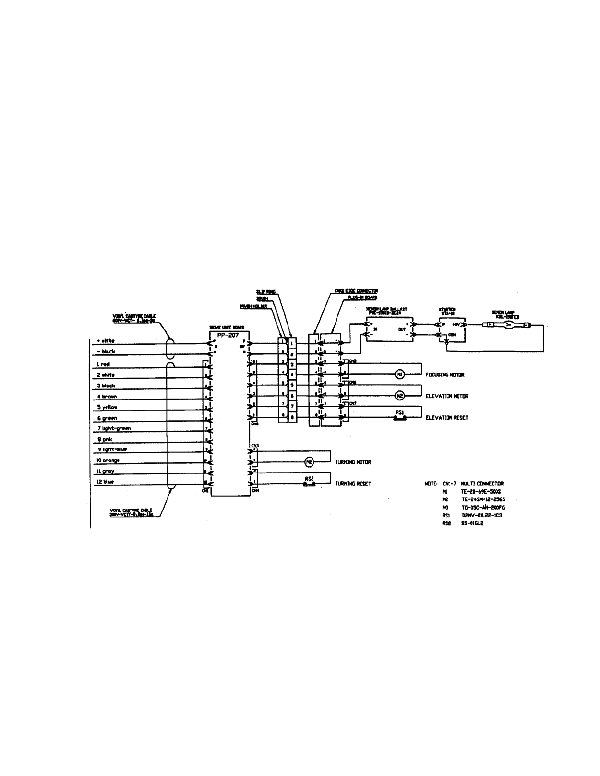
3.3 Wiring of Remote Control Panel (see Figure 3)
The Remote Control Panel is received with a 6-foot long, 20 AWG cable. The
cable will already be attached to the searchlight and should be connected to the
remote control panel connector to row.
Remote Control Panel
1
2
3
4
5
6
7
8
9
10
11
12
1
2
3
4
5
6
7
8
9
10
11
12
3.4 Searchlight Unit
The Searchlight Unit can be mounted where desired, using appropriate length
3/8", stainless steel fasteners. Keep navigational aids / GPS antennas out of the
beam path of the light. It is recommended to mount antenna 10 feet behind the
light minimum. Be sure the 4 nylon shoulder washers, supplied with the
searchlight, have been inserted in the searchlight base mounting holes to prevent
a galvanic reaction between the mounting hardware and the base of the
searchlight, and also that the mounting base gasket is securely in place before
bolting down. Silicone grease should be applied to the bottom of the gasket to
help in waterproofing the unit. When mounting, be sure that the unit is able to
rotate 360° without hitting any obstructions. Refer to Figure 4 for mounting
details. Mount unit so that the ID label on mounting base faces forward. This is
the home position when light is reset. (See instructions on controls) CAUTION:
The searchlight is not designed for inverted mounting.
CAUTION: Xenon-Arc lights emit electromagnet radiation, which may interfere
with some communication or navigation systems mounted on board.
Source DC 24V ± 10% 8.5A
Control Cable
AWG 20 0.5sq - 15c
FIGURE 3
Vinyl Castyre Cable
600V - VCT - 5.5sq - 2c
white
+
-
black
red
1
white
2
black
3
brown
4
yellow
5
green
6
light green
7
pink
8
light blue
9
orange
10
gray
11
blue
12
Vinyl Castyre Cable
300V - VCTF - 0.5sq - 15c
XENON SEARCHLIGHT
PP-307
+
-
1
2
3
4
5
6
7
8
9
10
11
12
CH1
Y1-03-0139 Rev. C 5
Page 7

The preferred location for communication and navigation equipment systems
antenna is at least 3 meters directly above the light.
After the light is installed, all critical communication and navigation systems
should be checked for proper operation with the light turned ON and rotated all
around.
FIGURE 4
Y1-03-0139 Rev. C 6
Page 8

3.5 Second Remote Control Panel (Slave) – optional
(Product No. 1942)
The second Remote Control Panel may be mounted similar to the first. The
second remote control panel is wired parallel to the first remote control panel.
Connect cable to sockets on back of control panels. Master panel should have
cable plugged into top socket row 2; slave panel should have cable plugged into
bottom socket row 1 (refer to Figure 5).
FIGURE 5
Y1-03-0139 Rev. C 7
Page 9

3.6 Instructions on Controls
Rotation –
Up/Down/Left/Right Move joy stick in the desired direction.
Low Speed Range 0° to 7.5°
High Speed Range 7.5° to 15°
Focus - Rotate focusing knob for desired light spot size (wide or narrow)
Operation of CPF99 Control Panel
FIGURE 6
Y1-03-0139 Rev. C 8
Page 10

3.7 Bulb Replacement (see Figure 7)
A 150W xenon short arc lamp is provided with your RCL-600A. If it should need
replacement, it must be ordered through ACR Electronics, Inc., by P/N A1-14-
0093.
To replace the lamps:
Warning: Do NOT touch glass or parabolic reflectors with fingers or tools! Use
cloth gloves.
1. Disconnect unit from power source and allow cooling.
2. Remove four screws holding front flange and glass with provided 6mm hex
wrench.
3. Loosen mounting collar of lamp by turning collar counter clockwise. Unhoo k
wire from opposite end of lamp. Pull lamp out of mounting collar. Installation
is done in reverse order.
4. Replace front flange and glass and install the four retaining screws. Be sure
gasket is securely in place.
5. Reconnect unit to power source.
FIGURE 7
Y1-03-0139 Rev. C 9
Page 11

Warning: Turn OFF the power witch when installing lamp.
1. Loosen the four (4) hexagon socket head cap bolts by using the attached
hexagon wrench and take the front frame off from lamp housing.
2. Turn the anode female collet counterclockwise to loosen the anode male
collet.
3. Take the xenon lamp out of the case. Hold the cathode side (-) before you
and insert the anode side (+) into the anode male collet securely.
4. Turn the female collet clockwise to tighten the lamp.
5. Insert the receptacle into the tab terminal securely.
6. Install the front frame with four (4) bolts.
Caution: If you handle the xenon lamp with dirty hands, wipe off the stain on the
glass with alcohol.
Y1-03-0139 Rev. C 10
Page 12

CONNECTION DIAGRAM, RCL-600A/12V
Table 1
* Source cable size
0 – 30 ft run: AWG 12
30 – 50 ft run: AWG 8
50 – 100 ft run: AWG 6
** Control cable size
0 – 100 ft run: AWG 16
*** Remote panels cable size
0 – 100 ft run: AWG 16
CONNECTION DIAGRAM, RCL-600A/24V
Table 2
* Main cable and source cable size
0 – 30 ft run: AWG 14
30 – 50 ft run: AWG 12
50 – 100 ft run: AWG 10
** Control cable size
0 – 100 ft run: AWG 16
*** Remote Panels Cable
0 – 100 ft run: AWG 16
Y1-03-0139 Rev. C 11
 Loading...