

Page 1
Y1-03-0229D
Page 2
CAUTION: Before proceeding to install, test or use your new ACR
Electronics’ product, please read this Product Support Manual in its
entirety.
If you have questions regarding the contents of the manual, please
contact our Technical Service Department at ACR Electronics, Inc.,
Telephone +1 (954) 981- 3333. Please be ready to provide the
technician with the page number you wish to discuss. If you have a
question that is not covered in the manual, please visit our website and
access the Frequently Asked Questions (FAQs) section for further
information or call our Technical Service Department. The website
address is www.acrelectronics.com. If in the future you lose this manual,
you may access and print a replacement on the ACR website.
About Cobham Life Support, ACR Products
Cobham Life Support, ACR Products, www.acrelectronics.com, designs
and manufactures a complete line of safety and survival products
including EPIRBs, PLBs, AIS, SARTs, Strobe Lights, Life Jacket Lights,
Search Lights and safety accessories. The quality systems of this
facility have been registered by UL to the ISO 9001:2000 Series
Standards. Recognized as the world leader in safety and survival
technologies, ACR has provided safety equipment to the aviation and
marine industries as well as to the military since 1956.
About Cobham plc
Cobham plc is an international company engaged in the development,
delivery and support of advanced aerospace and defence systems for
land, sea, air and space, The company has four divisions that
collectively specialize in the provision of components, subsystems and
services that keep people safe, improve communications and enhance
the capability of aerospace and defence platforms.
Y1-03-0229D
Page 3

PLEASE READ ALL WARNINGS, CAUTIONS
AND NOTES CAREFULLY
Table of Contents
SECTION1 - PRODUCT DESCRIPTION _________________________ 3
SECTION 2- SEARCHLIGHT MOUNTING _______________________ 4
SECTION 3 - REMOTE CONTROL SYSTEM _____________________ 5
SECTION 4 - URP-102 POINT PAD™ __________________________ 5
SECTION 5 - URC-300 MASTER CONTROLLER __________________ 7
SECTION 6 - POINT PAD™ OPERATION _______________________ 9
APPENDIX A - SPECIFICATIONS ____________________________ 11
APPENDIX B - KIT COMPONENTS ___________________________ 12
APPENDIX C - WIRING DIAGRAM ___________________________ 13
APPENDIX D - WARRANTY, USEFUL LIFE POLICY, NOTICES _______ 14
Y1-03-0232D 2
Page 4

SECTION1 - PRODUCT DESCRIPTION
Introduction
The RCL-300A was specially designed for mariners who require a high
intensity remote controlled searchlight that can stand up to the tough
marine environment.
The sleek design and modern construction of the searchlight body
makes it attractive for recreational and commercial vessels. The
searchlight is totally enclosed and is made of rugged aluminum alloy. It
is gasketed and finished to be resistant to the weather.
The RCL-300A searchlight contains a narrow beam searchlight that
produces 1,000,000 peak candle power by combining twin 35W metal
halide HD lamps providing over 500K candela (CD) each and 1 million
effective CD when combined.
All functions of the searchlight can be electrically operated by remote
control from the pilot area od the vessel using the URP-102 Point
Pad™, URC Master Controller and interconnect cable supplied with the
RCL-300A. Searchlights equipped with the URC-300 Master Controller
have a self-park feature and ACR’s unique XRCiZ™ feature. The
XRCiZ™ feature routinely operates all moving parts in the searchlight to
keep the motors and drive mechanisms freely running.
Unpacking the RCL-300A
Your new RCL-300A Remote Control Searchlight System comes with
the following components:
1.) RCL-300A searchlight
2.) URP-102 Point Pad™ with Installation Kit
3.) URC-300 Master Controller with Installation Kit
4.) Product Support Manual, Warranty Card, Mounting Templates, etc.
5.) Coaxial Cable Kit
Y1-03-0232D 3
Page 5
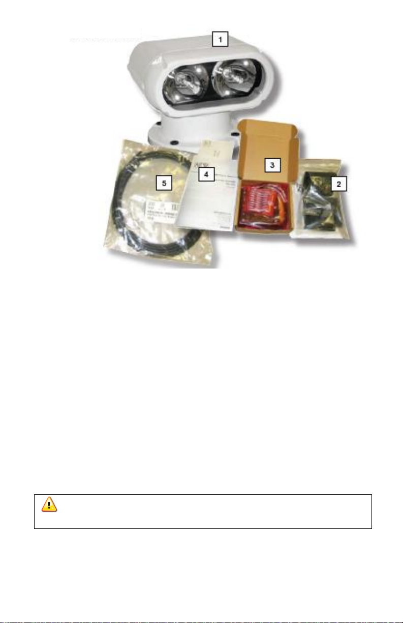
Figure 1- RCL-300A Components
SECTION 2- SEARCHLIGHT MOUNTING
Make sure the area is clean and dry. The searchlight can be mounted
where desired, using appropriate length 5/16” diameter stainless steel
fasteners. One set is provided in the mounting kit and four (4) nylon
shoulder washers. The nylon washers prevent a galvanic reaction
between the mounting hardware and the base of the searchlight. Be
sure these washers have been inserted in the base mounting holes and
that the mounting base gasket is securely in place before bolting down.
Apply silicone grease to the bottom of the gasket to help in
waterproofing the unit. When mounting, be sure the searchlight is able
to rotate 360° without hitting any obstructions. For the drilling hole
pattern, refer to the searchlight Mounting Template.
CAUTION: Do not mount the searchlight upside down. Moisture
cannot drain from the inverted light head assembly.
Y1-03-0232D 4
Page 6

Self Park Feature
The RCL-300A has a Self-Park feature. The Self Park function will
automatically return the light to a specific position when turned off.
When mounting the light, determine in advance the direction that the
light should face when it is turned off. Align the red marker on the base
180° opposite of the final facing direction.
To activate the Self-Park feature, press the “Speed” button on the UPR102 Point Pad™ for more than five (5) seconds.
Figure 2- URC-300 Master Controller unit (mounted upright)
Single Point Pad connection configuration
SECTION 3 - REMOTE CONTROL SYSTEM
The Remote Control System consists of the URC-300 Master Controller
and the UPR-102 Point Pad™. This system is compatible with 12 VDC
through 24 VDC systems without modification.
SECTION 4 - URP-102 POINT PAD™
Case options
The UPR-102 Point Pad™ is supplied as a surface mount unit (see
Figure 3). A flush mount option is provided. To switch mounting options,
unscrew the six (6) screws on the unit’s back plate and remove the front
cover. Fit the Point Pad™ with the flush mount cover, replace the back
plate and screw the unit back together.
Y1-03-0232D 5
Page 7

Mounting
Both the surface mount and the flush mount options require access to
the backside of the mounting location. Verify that there are not any
obstructions behind the area where the switch is to be located, e.g.,
bulkheads, wires, plumbing or hardware. Check that the coax cable from
the Master Controller can be routed to this location. Generally, the Point
Pad™ should be mounted in a protected area.
Surface Mount
Install the surface mount Point Pad™ by drilling
three (3) holes in the dashboard location using
the Point Pad™ Surface Mount Template
supplied in the Mounting Templates. Mount the
Point Pad to the dashboard using the gasket,
washers and nuts supplied. Apply a sealant
around the bolt holes to protect from moisture
intrusion.
Connecting to the Master Controller
The Point Pad™ communicates with the Master Controller via standard
television type RG-59 coaxial cable. The connectors are standard “F”
type television connectors. The connector on the back of the Point
Pad™ is located in the center of the panel for ease of installation. After
the coax cable has been routed and the “F” connector is attached to the
coax cable, screw the “F” connectors to the Master Controller and the
Point Pad™.
Additional Point Pads™ (up to three) may be used with one (1) Master
Controller. A standard “T” connector or RG-59 television type splitter is
used for each additional Point Pad™. Limit the total length of all coax
cable used to 300 feet.
Flush Mount
When the flush mount is selected, cut a
rectangular hole in the dashboard location using
the Point Pad™ Flush Mount Template supplied in
the Mounting Templates. Use the gasket, washers,
nuts and the two U-Clamps provided to secure the
Point Pad™. Apply a sealant around the cut out to
protect from moisture intrusion.
Y1-03-0232D 6
Page 8

SECTION 5 - URC-300 MASTER CONTROLLER
Master
Controller
Wire
Searchlight
Cable Wire
Wire Gauge
(AWG)
Power Source
Lead
Function
Orange
16
+12 VDC or
+24 VDC**
URC-300 Power
Blue 16
Ground
URC-300
Ground
Yellow
Yellow
16
Position Sensor
Signal
Green
Green
16
Position Sensor
Common
Red
Red
16 Up
White
White
16 Down
Black
Black
16 Right
Brown
Brown
16 Left
White
White
12
Lamp Power
Black
Black
12
Lamp Ground
Mounting
The Master Controller can be mounted in any position near the
searchlight that is protected from the weather. Check in advance that
the coax cable from the Point Pad and the wiring harness from the
searchlight can be routed to this location. Mount the Master Controller
with the wires and coax facing down. Use an appropriate fastener for
your mounting location. Use a sealant in fastener holes to prevent
moisture intrusion.
General wiring scheme
WARNING: The RCL-300 has a unique wiring scheme. Special
attention must be paid to the following chart.
The Master Controller is supplied with an in-line fuse-holder on the
Orange power lead. Use only 30 amp fuses in this fuse-holder. See
chart below for the Master Controller wiring diagram.
WARNING: Failure to follow this arrangement may damage
components.
Table 1
WARNING: This wire MUST be fused with a 30 amp fuse in the
Master Controller's in-line fuse-holder.
Y1-03-0232D 7
Page 9

Wiring to the searchlight
Figure 5
The RCL-300A searchlight is supplied with a 15-foot integral wire
harness. If you must lengthen the wire harness, use heavy duty wire to
minimize the voltage drop. This is especially important for the WHITE 12
AWG lamp power, BLACK 12 AWG lamp ground, ORANGE power wire
and BLUE ground wires.
Following the wiring scheme above and
Appendix C. use the supplied butt
connectors to connect the Master
Controller to the searchlight.
Wiring the Point Pad™
The RG-59 coax cable is supplied
without the “F” connectors attached for
ease of routing. After the Coax cable
has been routed, strip the insulation and
crimp the “F” connectors in place.
Screw the “F” connectors to the Master
Controller and the Point Pad™.
Wiring to the power supply
The power source must be a fused 12
VDC, 30-amp supply or a 24 VDC, 15amp supply. Following the wiring scheme in Table 1, use the supplied
butt connectors to connect the Master Controller to the power source.
Refer to Table 2 for proper wire size for connection of the input power
lines.
NOTE: As per the wiring scheme, the ORANGE wire is connected to the
positive terminal and the BLUE wire is connected to the negative
terminal of the power source.
CAUTION: HID light systems, when first turned on, have a high
inrush current requirement of 25 amps. If you activate the light and the
lamps flicker on and off repeatedly, check the voltage being supplied.
This condition can be experienced with voltage input of less than 11.5V.
Functions of the URC-300
The URC-300 Master Controller is designed to perform up to six
different duties on searchlights, winches and other electrical devices.
The Master Controller provides optimum voltage to ensure brightest
performance and long lamp life, regardless of boat system voltage
fluctuations. The Master Controller is compatible with devices requiring
12 VDC through 24 VDC operation.
Y1-03-0232D 8
Page 10

The URC-300 Master Controller has a searchlight motor time-out
feature. If a Point Pad™ rotation switch (right or left) is continually
engaged for more than 50 seconds, the Master Controller will interrupt
the operation until the Point Pad switch is disengaged. This feature will
save the searchlight motor from burnout due to accidental activation.
The elevation motor has similar features which will timeout in
approximately 20 seconds.
XRCiZ™ feature
The URC-300 Master Controller has the unique XRCiZ™ feature. The
XRCiZ™ feature routinely operates all moving parts of the searchlight to
keep the motors and drive mechanism freely running. Once activated,
and every 30 days thereafter, the XRCiZ™ feature wakes up and
operates the searchlight. The searchlight will rotate 360° in both
directions and the parabolic reflectors will move to the full up and down
positions. This feature keeps the searchlight in peak working order when
not in service for long periods of time.
To activate the XRCiZ™ feature, press and hold the Point Pad™
ON/OFF button for greater than 5 seconds. The green LED on the URP-
102 Point Pad™ indicates that the XRCiZ™ feature is enabled.
While the XRCiZ™ feature is operating the searchlight, pressing any
Point Pad™ button will stop the XRCiZ™ command.
To deactivate the XRCiZ™ feature, press and hold the Point Pad
ON/OFF button for greater than 5 seconds. The red LED on the URP102 Point Pad™ indicates that the XRCiZ™ feature is disabled.
NOTE: The Searchlight should not be covered while the XRCiZ™
feature is enabled.
Self- Park feature
The URC-300 Master Controller has a Self- Park feature. When the
Self-Park feature is activated, it will automatically return the searchlight
to the forward (or aft, if mounted as such) position when the searchlight
lamps are turned off. The feature also works with the XRCiZ™ function
to return the searchlight to it Self-Park position.
SECTION 6 - POINT PAD™ OPERATION
Press the On/OFF button to turn the lights ON or OFF.
Press the SPEED button to toggle between High and low rotation
speeds.
Press the Right or Left arrows to rotate the searchlight in the
direction.
Y1-03-0232D 9
Page 11

Press the Up or Down arrows to raise or lower the searchlight beam.
Figure 6
To activate the XRCiZ™ feature, press and hold the ON/OFF button
for more than 5 seconds. The green LED ind9cates that the XRCiZ™
feature is enabled.
To deactivate the XRCiZ™ feature, press and hold the ON/OFF
button for more than 5 seconds. The red LED ind9cates that the
XRCiZ™ feature is disabled.
An LED blinking red/green indicates that then XRCiZ™ feature is
now “exercising” the searchlight.
To activate the Self-Park feature, press and hold the Point Pad™
Speed button for more than 5 seconds.
While the Self-Park feature is operating the searchlight, pressing any
Point Pad™ button will stop the park command and leave the
searchlight to follow any additional commands.
To deactivate the Self-Park feature, press and hold the Point Pad™
Speed button for more than 5 seconds.
An LED blinking re/green indicates that the searchlight is seeking its
Self-Park position.
The Self-Park and XRCiZ™ features are normally disabled when
power is lost to the URC-300 Master Controller and will have to be
reactivated.
NOTE: Self-Park and the XRCiZ™ features are only available when
paired with a URC-300 Master Controller.
Y1-03-0232D 10
Page 12

Characteristics
Specification
Size
12 X 13 X 9.3 in (31 X 33 X 23.5 cm)
Weight
31 lb (14.06 kg)
Material
Cast aluminum, tempered glass
Input voltage*
12V- 24V
Amp draw
Startup 25A @ 12V, Running 8A @ 12V
Color
White
Operation
Remote controlled Point Pad™
Beam spread
6°
Elevation angle
12° up, 38° down
Rotation
360° continuous
Rotation speed
Fast 30° per second, Slow 12° per second
Elevation speed
7° per second
Lamp
- Twin 35W metal halide lamps
- 1,000 hours operating life
Accessories
- Secondary Point Pad for remote control with Install
Kit (ACR P/N 9282.3)
- Replacement 35W halide lamp (ACR P/N 6009)
Footprint diameter
9 in (23 cm)
Limited warranty
1 year
Carton dimensions
20.5 X 14.25 X 19.25 in (52.07 X 36.20 X 48.90 cm)
Carton weight
40 lb (18.14 kg)
APPENDIX A - SPECIFICATIONS
*CAUTION: HID light systems, when first turned on, have a high
inrush current requirement of 25 amps. If you activate the light and the
lamps flicker on and off repeatedly, check the voltage being supplied.
This condition can be experienced with voltage input of less than 11.5V.
Y1-03-0232D 11
Page 13

APPENDIX B - KIT COMPONENTS
Description
Quantity
ACR Part Number
Searchlight, RCL-300A
1
A3-06-2558
Point Pad™, URP-102 with surface mount
case
1
A3-06-2230
URC-300 Master Controller unit
1
A3-06-2231-1
Case, flush mount
1
A1-18-1875-2
Gasket, surface mount
1
A1-25-0140-1
Gasket, flush mount
1
A1-25-0140-2
U Clamp
2
A1-17-1366
Nuts, nylon- lock
2
A1-05-0776
Washers
2
A1-05-0777
Cable, coaxial
30ft
A2-07-0002-6
Connector, “F”
2
A1-03-0220
Flanged 8 steel 12-10 AWG
2
A1-05-0861-8
Flanged 8 stud 16-14 AWG
8
A1-05-0861-5
Product No. 1930.3 - RCL-100D 12 V Searchlight Installation Kit
includes:
Y1-03-0232D 12
Page 14

APPENDIX C - WIRING DIAGRAM
Y1-03-0232D 13
Page 15

APPENDIX D - WARRANTY, USEFUL LIFE POLICY,
NOTICES
Limited Warranty
This product is warranted against factory defects in material and workmanship for a
period of 1 (one) year* from date of purchase or receipt as a gift. During the
warranty period ACR Electronics, Inc. will repair or, at its option, replace the unit at
no cost to you for labor, materials and return transportation from ACR. For further
assistance, please contact our Technical Service Department at ACR Electronics,
Inc., 5757 Ravenswood Road, Fort Lauderdale, FL 33312-6645. Email:
service@acrelectronics.com, Fax: +1 (954) 983-5087, Telephone: +1 (954) 981-
3333.
This warranty does not apply if the product has been damaged by accident or
misuse, or as a result of service or modification performed by an unauthorized
factory. Except as otherwise expressly stated in the previous paragraph, THE
COMPANY MAKES NO REPRESENTATION OR WARRANTY OF ANY KIND,
EXPRESS OR IMPLIED, AS TO MERCHANTABILITY, FITNESS FOR A
PARTICULAR PURPOSE, OR ANY OTHER MATTER WITH RESPECT TO THIS
PRODUCT. The Company shall not be liable for consequential or special damages.
To place the warranty in effect, register online at www.acrelectronics.com or return
the attached card within 10 days.
*Five years for the following products: EPIRB, PLB, S-VDR, SSAS.
Useful Life Policy
The typical service life of a properly maintained Product is limited to 12 years from
date of manufacture. Products that are 12 years and 1 month or older from date of
manufacture will not be serviced by ACR or our Battery Replacement Centers. A
Product that is 12 or less years old from date of manufacture will be serviced as
long as the unit appears fit to be placed back into its final operational cycle. Service
includes the replacement of those items that must be replaced at service intervals
and the verification that the device appears to be in good mechanical and electrical
working condition by an ACR authorized service technician.
Notices
ACR Electronics diligently works to provide a high quality Product Support Manual,
however, despite best efforts, information is subject to change without notice, and
omissions and inaccuracies are possible. ACR cannot accept liability for manual
contents. To ensure that you have the most recent version of the Product Support
Manual, please visit the ACR website at www.acrelectronics.com.
©2008 by ACR Electronics, Inc., part of Cobham plc. All rights reserved.
Reproduction in whole or in part is permitted only with permission of ACR
Electronics, Inc. Ongoing product improvements may change product specifications
without notice.
Trademarks or registered trademarks are the property of their respective owners.
Y1-03-0232D 14
Page 16

EC DECLARATION OF CONFORMITY
ACR Electronics, Inc. hereby declares that the following product is in conformity with
Directive 2004/108/EC of the European Parliament and of the Council of 15
December 2004 on Electromagnetic Compatibility (EMC Directive). In accordance
with the Directive, the product will be marked with the CE conformity marking as
follows:
Product: Searchlight
Model: RCL-300A
Regulations and EN 60945: 2002: Emissions:
Standards: CISPR 16-1:1999 (Conducted Emissions)
CISPR 16-1:1999 (Radiated Emissions)
EN 60945: 2002: Immunity:
IEC 61000-4-2: 1995 (Electrostatic Discharge)
IEC 61000-4-3: 1995 (Radiated Immunity)
IEC 61000-4-6: 1996 (Conducted Immunity, Power
and I/O Leads)
IEC 61000-4-11: 1994 (Voltage Dips and Interrupts)
Manufacturer: ACR Electronics Inc. European ACR Electronics Inc.
5757 Ravenswood Road Representative: (European Office)
Fort Lauderdale, FL 33312 1 Rose Cottages, Pitmore Lane,
USA Sway, Lymington, Hampshire
SO41 6BX UK
Signed on behalf of ACR Electronics Inc.
Signed: __________________________________________
Name: Kerry Greer Date: February 26, 2009
Title: Executive Director -
Research & Development
Document RCL-300-002 This Declaration complies with
ISO/IEC 17050-1:2004
ACR Electronics, Inc. is registered by UL to ISO 9001:2000
Y1-03-0232D 15
 Loading...