

Acoustic Research AR-3 Service manual
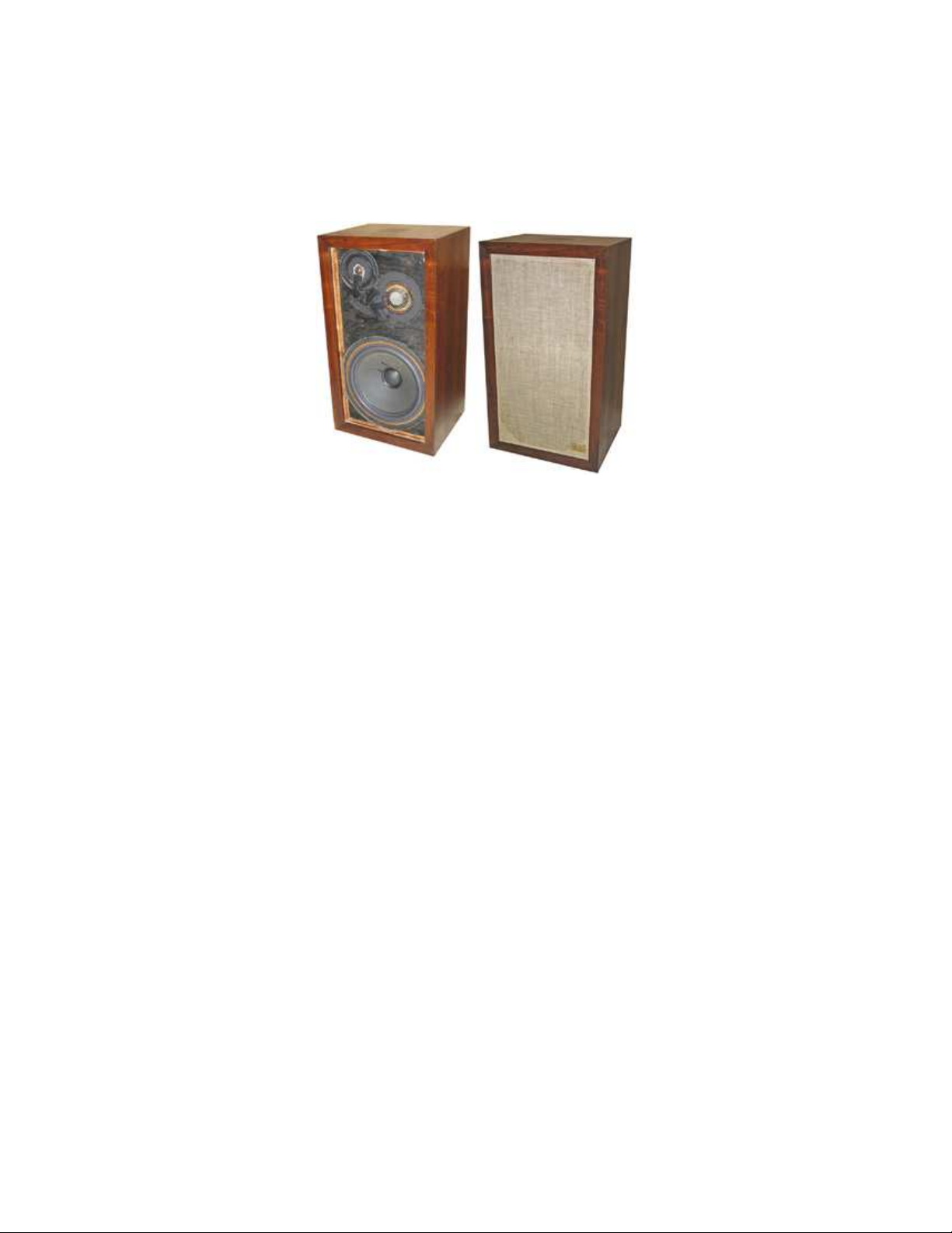
Restoring the AR-3a 2007 The Classic Speaker Pages
1
Restoring the AR-3a
Roy Champagne, Ken Kantor, Minh Luong, John O’Hanlon (Ed.), Bret Thiel, and Tom Tyson
6 December 2007
Welcome fellow AR traveler! If you are reading this, you are probably considering repairing or
restoring an old AR-3a pair. For some, this restoration process is an afternoon of effort and a few
dollars in supplies—just to get some reasonable sounds going. For others, it is a consuming quest
for perfect authenticity. Either way, it's a lot of fun and a good learning experience. Only you can
decide how much time and money you want to devote, and the job also depends on the physical
and electrical condition of your speakers. As a first step, take a look at the flow-chart included
here to get an idea of the task at hand. Many of us are very passionate about the 3a and consider
it a landmark product in the history of loudspeaker development. A properly restored pair can
sonically rival the best modern speakers and will reward the investment of effort put into them.
However, even a basically repaired pair will be capable of providing much listening pleasure for
years to come. [KK]
Table of Contents
1 What is it? 2 3.9 Replace the Capacitors? Options 16
2 Identifying and Checking Components 2 3.10 Early Woofer Inductor Replacement 17
2.1 Useful Tools 2 3.11 Grilles and Badges 17
2.2 Getting Started 3 4 Re-assembly 19
2.3 Removing the Grille 4 4.1 Gasket Materials 19
2.4 Check for Visible Damage 4 4.2 Installing Mid- and Hi-range Drivers 20
2.5 Low-Level Listening 5 4.3 Stuffing the Cabinet 21
2.6 Woofer Diagnosis: Low Level Audio 5 4.4 Installing the Woofer 21
2.7 Mid-Range Diagnosis: Low Level Audio 6 4.5 Testing for Acoustic Leaks 22
2.8 Hi-Range Diagnosis: Low Level Audio 6 4.6 Remounting Grilles and Badges 22
2.9 Play it Again, Sam 6 4.7 Testing Your Speakers 22
2.10 All Systems “Go” 7 4.8 Finished! 23
3 How to Fix It 7 Acknowledgement 23
3.1 Removing Woofer 8 Appendix: Driver Identification 23
3.2 Removing Mid-range and Hi-range 8 A.1 Woofers 23
3.3 Repair or Replace the Woofer? 8 A.2 Mid-range Drivers 24
3.4 Removing the Stuffing 9 A.3 Hi-Range Drivers 25
3.5 What’s Inside? 9 A.4 Driver Images 26
3.6 Replace the Mid-range driver? 11 Woofer 27
3.7 Replace the Hi-range driver? 11 Mid-Range 29
3.8 Replace or Restore Potentiometers 13 Hi-Range 31

Restoring the AR-3a 2007 The Classic Speaker Pages
2
1. What is it?
The AR-3a is a three-way acoustic suspension loudspeaker manufactured from 1967–1975. Its
specifications are: External cabinet size: 14×25×11-3/8” (356×636×289 mm). Weight: 53 lb. (24
kg.). Drivers: 12” woofer, 1-1/2” mid-range, 3/4” hi-range. Average woofer free-air resonance:
18–21 Hz. Average resonance with cabinet stuffed: 42 Hz. Crossover frequencies: Mid-range,
575 Hz; Hi-range, 5000 Hz. Internal volume: 1.48 ft3 (41.8 liters). Impedance: 4 Ω. Independent
mid-range and hi-range driver level controls.
Each of us has their own reason to restore and enjoy the AR-3a. Here’s one person’s view:
“In those years the AR-3a was considered to be the best made in the U.S. They had been
crowned the king of speakers in South East Asia, where they were well known in Vietnam, Hong
Kong, and Taiwan. In 1972 I first encountered the AR-3a in Vietnam in my Uncle’s house and in
my Father's best friend’s music room. I loved them for many reasons. They were expensive and
owning a pair was like owning a Corvette; it was a symbol of high class and good taste. They
were built like a tank and meant to last forever, which we have proven to be true 40 years later.
The sound quality was superb and for the price, there was no other speaker that could come
close. The signature solid deep bass made it one of a kind. The uncolored mid-range and the
ability to deliver music and vocals as close to the real thing made the AR-3a as one of my all
time favorite speakers. They are small enough to stuff into an area where other speakers may
have problems. The wide dispersion drivers set them free from sweet spot listening. Regardless
of their simple and primitive crossover and drivers, they still remain very accurate compared to
other speakers that were designed with computer aided programs. After experiencing the AR-3a, I
turned into a real ‘AR fanatic.’ I am still trying to break my habit.” [ML.]
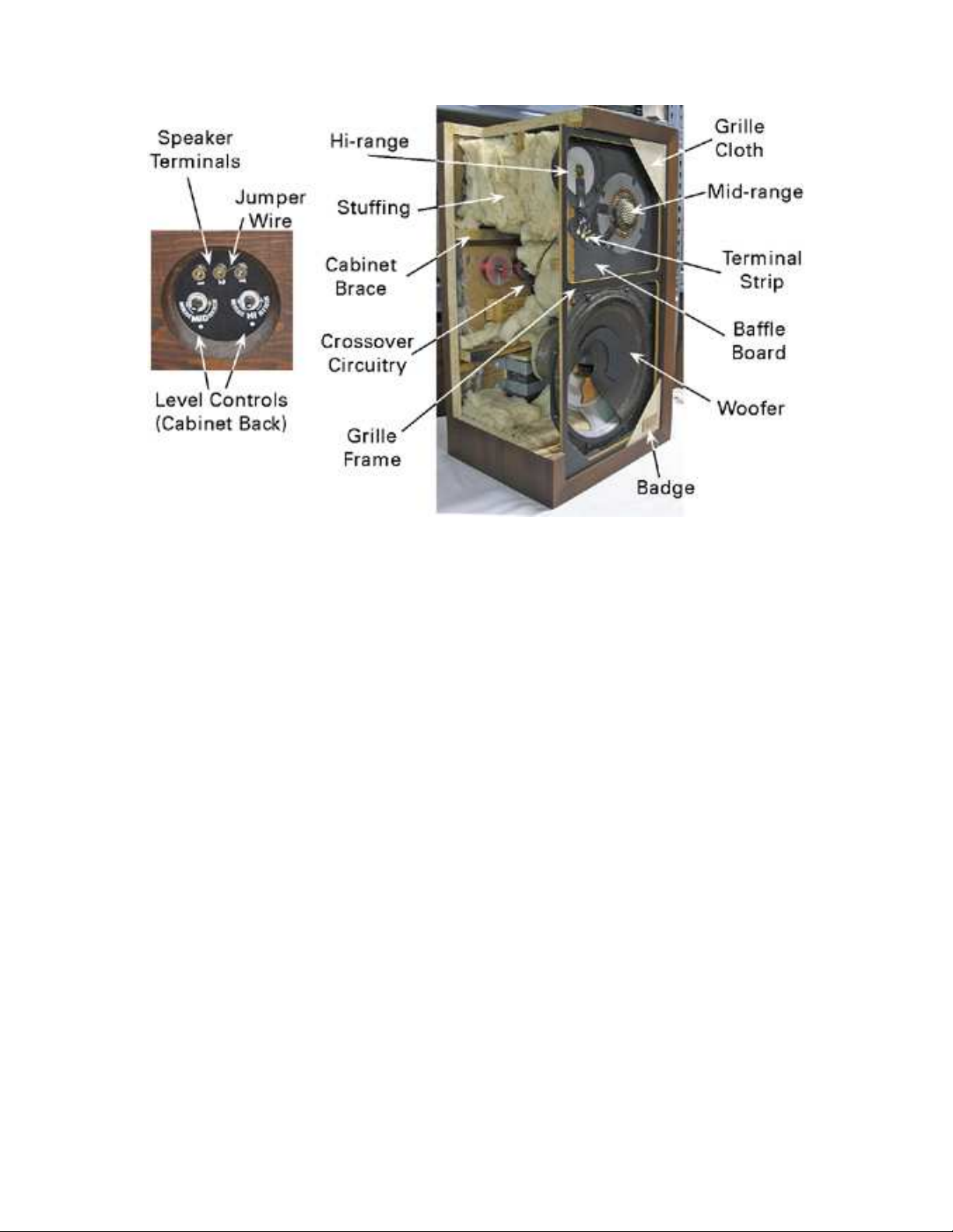
2. Identifying and Checking Components
Figure 2.1 identifies the major components of an AR-3a. Early models used “front-wired” or
“hard-wired” mid- and hi-range drivers, so named because their lead wires were soldered to a
terminal strip on the baffle board. The late model used push-on connectors that mated with back
mounted male tabs. Amplifier connections for full range operation are made to posts 1(–) and
2(+) on the rear, provided that a jumper wire is connected between posts 2 and T. The jumper
wire is removed for use as a woofer only. The cabinet was acoustically sealed with gaskets under
each of the three drivers. Air leaking around level control shafts and amplifier terminals provides
a small amount of air permeation needed to prevent the cabinet from becoming too tightly sealed.
2.1 Useful Tools
Some tools are necessary; others are useful. Here are some recommended items:
Soldering iron; 30–50 W. Volt-Ohm meter (very helpful)
Solder; 0.032- or 0.065-in. diameter rosin core Capacitance-inductance meter (optional)
Solder wick (finely braided copper) Small, wide-blade putty knife
Long nosed pliers Rubber gloves
Side cutting pliers Dust mask
Phillips screwdriver; #3 (or #2) Plastic or paper bags to hold stuffing
Flat-blade screwdrivers; 4-in. and 2-in. Padding to protect the cabinet’s finish
1.5-V AA cell, battery holder, and leads Digital camera
Small magnet (helpful) 3/4-in. adjustable end wrench
Restoring the AR-3a 2007 The Classic Speaker Pages
3
Fig. 2.1 Early AR-3a component layout; Rear panel (Left), Cutaway view (Right)
Please be sure that the lead resistance of your volt-ohm meter (DVM) does not affect the
resistance measurements. High-quality meters have a “null” or zero adjustment. To use this,
short the tips of the leads together and press the “null” function, or manually adjust its zero
setting on the lowest-resistance scale. If you do not do this, the error may be so great that you
may think a good driver is a dead short, or a 4-Ω driver that should read 3.5-Ω is an 8-Ω driver
that should read 6.5 Ω! The meter should read “0” on a 200-Ω full-scale resistance scale, when
its lead tips are shorted. You may also check it by measuring a known, low-value resistor.
Internal connections are usually soldered. Three solders are commonly available: i) 62.3%–
37.7% tin-lead (Sn–Pb) solder with a melting point of 183°C (364°F). It is readily available, but
has been phased out of electronics manufacturing to eliminate lead. ii) Lead-free solder, Sn–Cu–
Ag is available in electronics or hobby stores. It melts at ~220°C (428°F). iii) A special alloy,
Sn–Pb–Ag (62%–36%–2%) is made especially for soldering silver (Ag) plated copper wire. It is
not needed here but works well. If you find soldering intimidating, wire nuts will work just fine.
Eighteen-gauge Sn-plated Cu wire with colored insulation is available from big box stores or
electronic supply houses, should one wish to retain the original AR wire colors when re-wiring.
Eighteen-gauge is sufficiently large for AR-3a internal wiring.
2.2 Getting Started
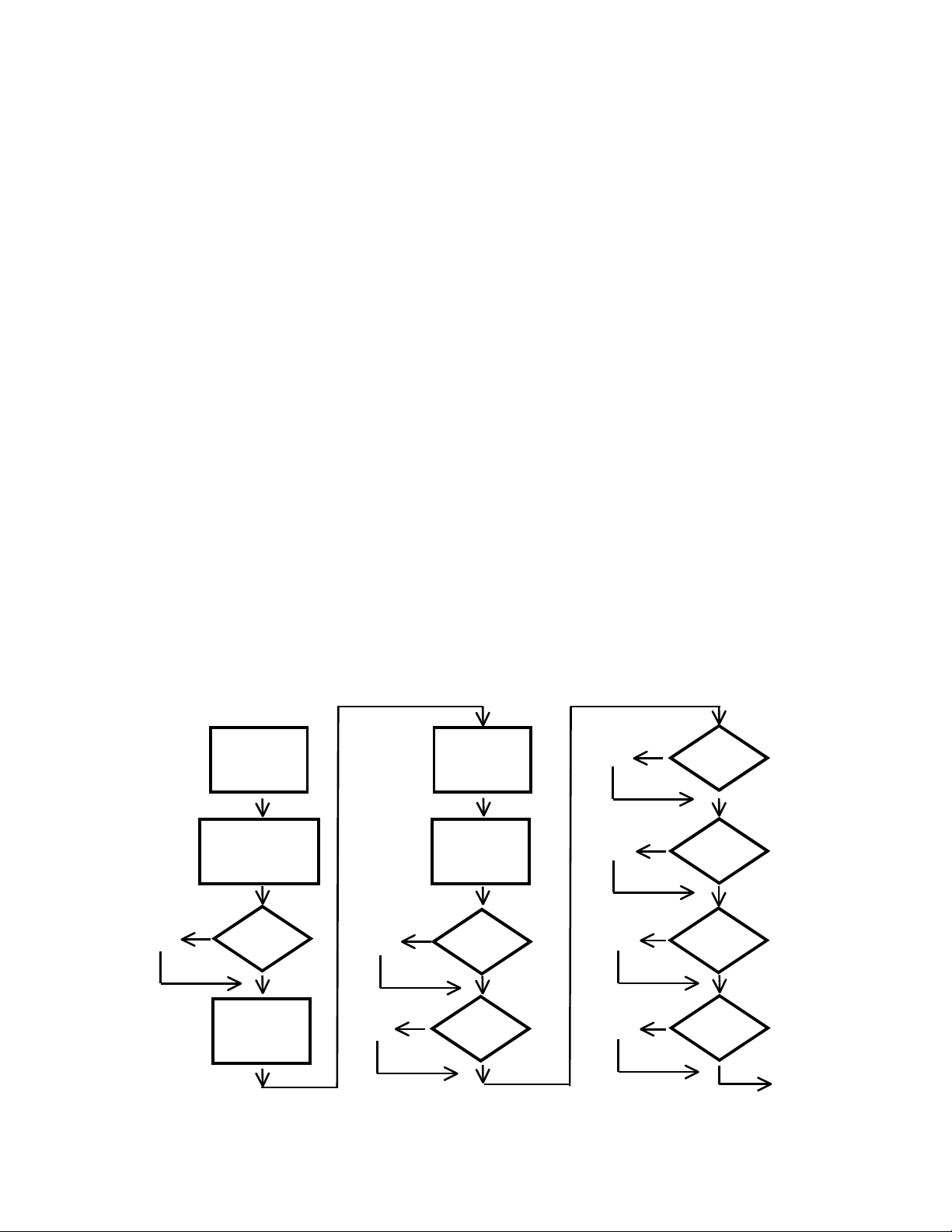
Our “Tables of Contents” are flow charts, like Fig. 2.2, designed to help those with non-technical
backgrounds. We suggest that you begin by following this path. At junctions, you will be
directed to specific text (§2.x) that will be found on the following pages. Detailed repair options
are given in §3 and re-assembly instructions in §4. Much—perhaps excessive—detail is provided
throughout this note especially for those who love music but have never opened a speaker or
experienced the joy of sitting through exciting sophomore circuit lectures.
Restoring the AR-3a 2007 The Classic Speaker Pages
4
Remove
Grille
§2.3
§2.6
N
Woofer
OK?
Play it
Louder!
§2.9
Y
Mid-range
OK?
Y
Hi-Range
OK?
Y
OK?
Y
All Systems
“Go”
§2.10
§4.7
N
§3.0
§2.4
N
Drivers
OK?
Apply Low
Level Audio
§2.5
Y
§2.7
§2.8
N
N
Fig. 2.2. Speaker analysis
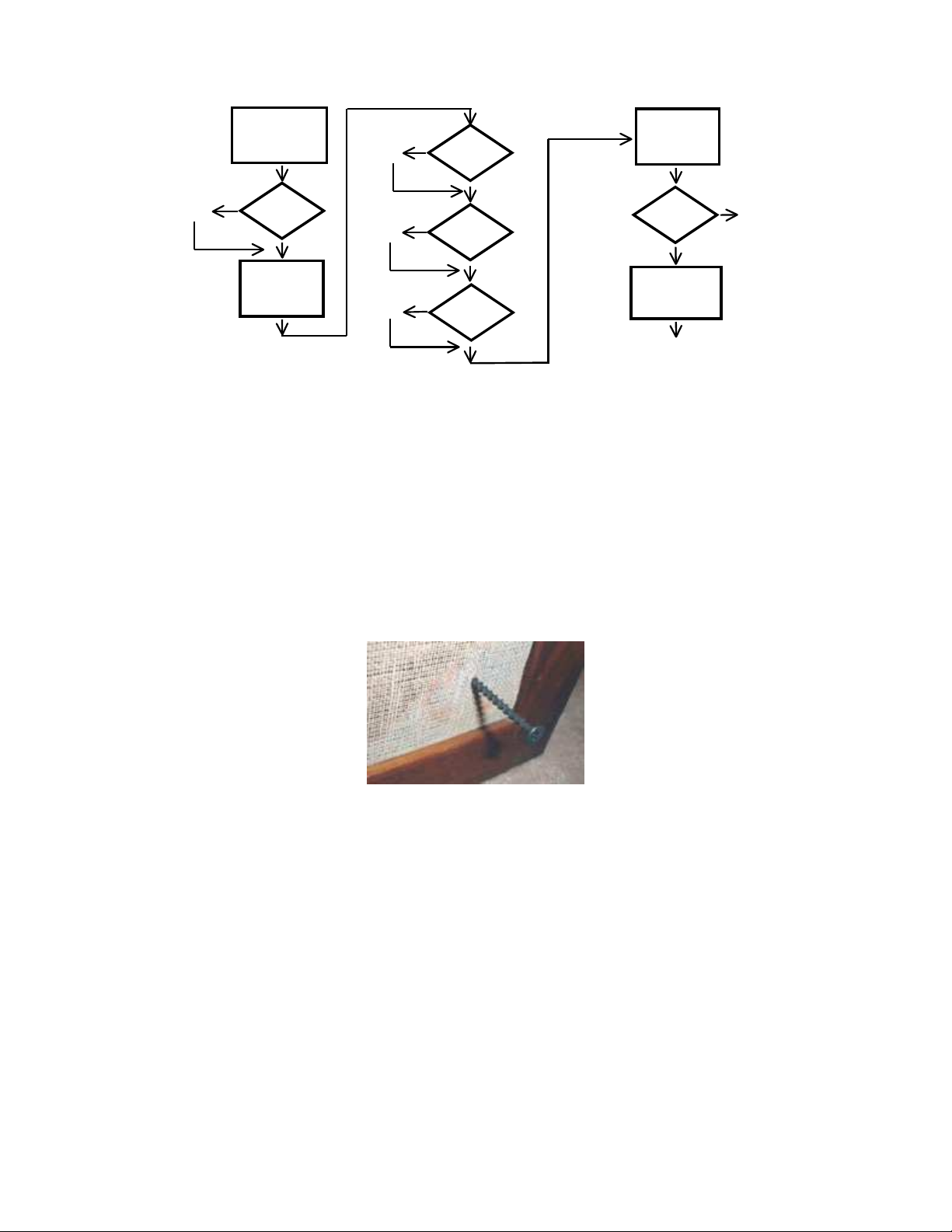
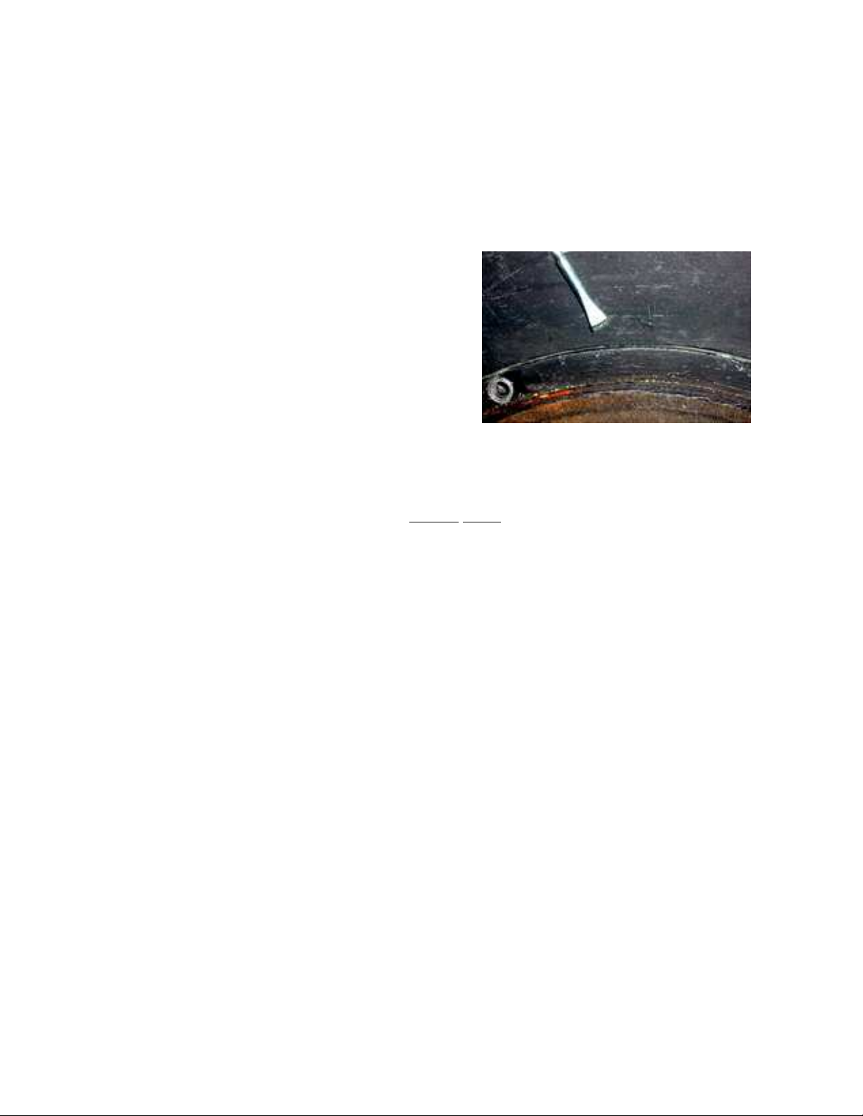
2.3 Removing the Grille
Early grilles were attached to the cabinet baffle board with hot glue. Fortunately hot glue dries and
becomes brittle with age; it usually pops free easily. Great care should be used to remove the grille
without damaging the cabinet’s finish! Two options: the best uses a screw and pliers [R.C.]. After
unscrewing the badge, screw a 1-5/8–2-1/2-in. drywall screw into the original badge screw hole. See
Fig. 2.3. Hold the screw with pliers and pop the grille corner free. The second method is not so easy;
it uses a thin screwdriver to pry the grille free by levering against a flat surface such as a putty knife.
Work the blade around the cabinet edge. There are typically 6 glue spots; one in each corner and one
on each side. Store the grilles safely where your cat cannot find them until the project is completed.
Fig. 2.3. Using a drywall screw to remove the grille.
2.4 Check for Visible Damage
Examine each driver for obvious problems. Look for damage to the hi-range cone, mid-range
mesh cover, and the woofer’s dust cover, cone, and surrounds. Gross damage is easily spotted.
Small dents in the hi-range dome are OK, they will not affect the driver performance. Larger
dents in the hi-range cone usually can be removed by applying suction with small-diameter soft
plastic tube. Small dents can be removed with a small needle, if necessary. If dome is completely
crushed or popped free, there’s no option; replace the driver.
The mid-range driver is fairly rugged, but small dents in its mesh covering are common.
Minor dents can be removed with a pair of small pliers or screwdriver.
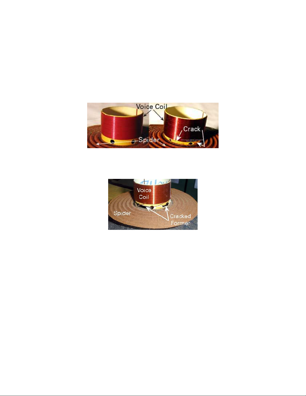
Major woofer damage (deteriorated surrounds, torn cones) requires immediate attention. The
Alnico magnet woofers in early AR-3a speakers were made with cloth surrounds; later woofers
used urethane foam surrounds. See Appendix for woofer images including a deteriorated foam
Restoring the AR-3a 2007 The Classic Speaker Pages
5
surround illustrated in image A.6. The early woofer will look its age; its surround will be wrinkled,
but that’s fine. The most common visible defect in the foam-surround woofer is deteriorated foam.
If the foam or cone is damaged, the cabinet will not be airtight and severe damage will result when
played loudly. A large signal will cause the voice coil excursion to exceed its nominal ~1-in.
excursion and “bottom” against the magnet plate, because there is no air suspension to restrain its
movement. Figure 2.4 illustrates damage caused when the voice coil former collided with the
magnet. Figure 2.5 shows a different kind of voice coil former damage; this former cracked and
separated from the spider after colliding with the magnet. Hopefully, these images will encourage
you to repair your woofer before potentially inflicting added expensive damage.
Fig. 2.4. AR-12-in. voice coil and spider assembly: (Left) Working condition. (Right) crushed from
hitting the magnet when played too loudly with a damaged surround.
Fig. 2.5. This voice coil former has completely separated from the spider after being played too loudly
with a damaged surround. If you do not know where the spider sits inside the woofer, please examine the
cutaway view of the AR-3a illustrated in Fig. 2.1
.
If the cone moves freely, because it has a rotted or torn surround or a hole in the cone,
proceed no further. Please repair the woofers! Options are given in §3.3. See §3.1 for instructions
on removing woofer and packing for shipping. You may choose, at your own risk, to apply small
signals and proceed farther along this path to determine if all the drivers speak and the
potentiometers are scratchy; but you risk voice coil damage.
2.5 Low-Level Listening
Connect an amplifier to each speaker and play low-level music. The amplifier should be known
to be in good condition and capable of driving a 4-Ω load. Music is preferred to a sine wave
generator so that one will not apply excessive single frequency power to the hi- or mid-range.
2.6 Woofer Diagnosis: Low Level Audio
How does it sound? Rattles? Vibration? Some rattles and buzzes, caused by a separation between voice
coil and cone or from sagging spiders don’t show up until played loudly; leave this for later. Check

Restoring the AR-3a 2007 The Classic Speaker Pages
6
surround edges for cone or basket detachment. If surrounds looks OK, it could still be partly detached,
or if early cloth surround, need to be re-coated. Check for cabinet sealing leaks by depressing the dust
cover gently with three fingers around its periphery. The dust cover is the small dome in the center of
the woofer. It should take 1-1/2–2 sec. to return. If the return is fast, then look more closely for leaks at
the surround’s edges. This is not the only cause of air leaks! They can be caused by something as
simple as a missing driver bolt, a loose potentiometer shaft screw, or missing gasket putty.
Should you have an early AR-3a Alnico cloth-surround woofer (Appendix Fig. A.1), the air leak
could be through the cloth surround that has lost some of its butyl-latex coating. One current coating
that has been suggested is Permatex 80062 High Tack Gasket Sealant. [RC] It can be brushed very
sparingly on the old cloth surround with a small, stiff brush to form a very thin coat. A thick coating
can increase the driver’s resonant frequency. Let it dry a day and recheck by depressing dust cover.
Latex-based surround glues are not recommended; they are too stiff, relatively, and increase the
woofer’s resonant frequency. The Permatex coating dissolves in the original and remains supple;
however, it is not suitable for use on foam surrounds!
If no audible signal is heard, either the voice coil is open, or there is a loose internal wire.
That can be sorted out when the cabinet is open. Vibration or buzzing usually indicates a loose or
poorly aligned voice coil. A lead wire touching the cone will occasionally cause rattling.
Obvious damage must be fixed before playing loudly, as that would only increase the damage.
See §3.1 for instructions on removing woofers.
2.7 Mid-Range Diagnosis: Low Level Audio
Listen to the mid-range output. Rotate the mid-range level control and listen for static or
intermittent signal. The mid-range driver is sturdy; however, it has been blown by playing at
excessive volume. If no sound, it could be an open voice coil, a corroded mid-range
potentiometer, or a loose wire. These can be sorted out when the cabinet is opened. If rotating the
pot results in intermittent sound, the pot needs cleaning—this is a common mid-range issue. See
Section §3.8 for instructions. Electrical problems can be diagnosed after it is removed from the
cabinet. See §3.2 for instructions on removing the mid-range driver. Next check hi-range driver.
2.8 Hi-Range Diagnosis: Low Level Audio
Listen to the hi-range driver output. Rotate the hi-range level control and listen for static or
intermittent signal. The high-range driver is most frequently blown by listening at very high
volumes or by driving the speaker with an under-powered amplifier. If no sound, it could be an
open voice coil (a common problem), a corroded hi-range potentiometer (“pot”), or a loose wire.
If rotating the pot results in intermittent sound output, then the pot is the culprit—this is the other
common hi-range problem. See Section §3.8 for instructions. Electrical problems can be
diagnosed after removal from cabinet. See §3.2 for instructions on removing the hi-range driver.
2.9 Play it Again, Sam;
... this time louder! Listen for clean output from all drivers. If the mid- and hi-range drivers are
functional, but the pots are intermittent, try to find one spot where the pots work for testing.
If the woofer was not damaged or has been repaired, play speakers at high volume to
determine if woofers are problem free before opening cabinets. Never play at high volume on an
under-powered amplifier; that will destroy the hi-range! Test with an amp of about 50-W per
channel capable of driving a 4-Ω load that is known to operate properly in both channels. Listen
for woofer rattles and buzzes; they would be caused by a small separation between voice-coil
bobbin and cone, or sagging spiders and not be heard until the speaker is played at high volume.
For example, one woofer “buzzed” only when one note on one organ work on one CD was
Restoring the AR-3a 2007 The Classic Speaker Pages
7
played at high volume—it was due to a partly detached voice coil. This driver was played loudly
at some earlier time when its surrounds were bad; this is an issue with Internet auction purchases.
If the spider has sagged from age, the cone will not sit in the correct proper position. If you
hear loud “clicking” when increasing the volume, immediately reduce the volume to prevent
more damage; clicking is caused by the cone hitting the magnet. Either the cabinet isn’t airtight,
or the voice-coil former is damaged, or the spider has badly sagged. To check the neutral
position of the cone, lay the speaker on its back. Lay a reference edge across cabinet, not
touching surround. Measure distance from reference edge to dust cap top. With 3 fingers, depress
cone gently around the edge of dust cap until back plate is contacted and measure the distance.
The difference should be 1/2 in. (12.5 mm) for older woofers. If it is less, say 3/8-in. (10 mm), it
is an indication that the spider has needs to be replaced. Late model woofers have very stiff
spiders. See §3.1 for instructions on removing the drivers.
2.10 All Systems “Go”
If all drivers work well, the cabinet is sealed, and the pots work properly, test them as described
in §4.7, then impress your friends. Perhaps, after some months, you may hear something that you
don’t think sounds right. At that point, you may wish to measure the capacitors and see if they
have drifted enough to require replacement. If not, you have an excellent pair of speakers that
need no work inside their cabinets. Now you can deal with the condition of the grilles and
badges. See §3.11. Minor blemishes in the cabinet finish can be repaired without removing the
drivers; however, the drivers and stuffing should be removed before a major refinishing project
is undertaken. The remainder of this document can be filed for future use.
3. How to Fix It
Repair requires removing the drivers to access the crossover components shown in the cutaway
view, See Fig. 2.1. A suggested repair sequence is given in Fig. 3.1.
§3.3
Remove
Woofer
§3.1
Remove
Mid-Hi-Range
§3.2
Repair
Y
Woofer?
N
Remove
Stuffing
§3.4
§3.6
§3.7
Crossover
Layout
Crossover
Circuit
Y
Replace
Y
Replace
§3.5
§3.5
Mid?
Hi ?
Y
Y
Y
Y
Repair
Pots?
N
Replace
Caps?
N
Replace
Coil?
N
Restore
Grille?
N
§4.0
§3.8
§3.9
§3.10
N
§3.11
N
Fig. 3.1. Suggested repair sequence.
Restoring the AR-3a 2007 The Classic Speaker Pages
8
3.1 Removing Woofer
Lay the speaker on its back and rest it on two small spacer blocks to prevent damage to the level
control knobs. Remove the woofer by carefully removing the 8 Phillips machine screws, being
careful not to press down on the screwdriver when loosening. There are “T-nuts” on the
underside and these can dislodge if you press too hard on the screwdriver. Clean the Mortite off
the threads of early AR-3a woofers and very, very lightly oil the threads; then clean with a rag
and set the screws aside where they will not be collected by any of the driver magnets.
Carefully go around the woofer frame with a
screwdriver or paint can opener to work the woofer
loose from the cabinet. The woofer is ~1/8th-in.
smaller than its opening in the baffle board. See Fig.
3.2. Be patient and careful, and it will finally
release.
Lift the woofer to the baffle board taking care
not to come near the mid- or hi-range. Remove
nearby magnetic objects lest the woofer magnet
suddenly cause them to move, perhaps damaging a
hi-range driver on the way by! Early woofer leads
need to be unsoldered from the terminal block.
Later woofers used easily removable 0.205-in-wide
(5.2-mm) push connectors.
Fig. 3.2. Using a paint can opener to lift the
woofer from its back bore.
Move the woofer to a safe location in the magnet down position, keeping screws and other
magnetic materials away from its large magnet. This editor now owns a nice wrench that
someone, somewhere still can’t find. An optional second method of removing the woofer
involves removing the mid-range with a screwdriver or opener and pushing the woofer out from
its underside.
Carefully scrape the Mortite gasket material from the cabinet and the bottom of the woofer,
or remove the gasket if it has one. Remove the crepe-like paper, “Kempac,” (if it has it) just
below the speaker hole where the wires go through; save this paper.
If the woofers are to be shipped for re-foaming, they need to be packaged carefully so that
voice coil and cone cannot be knocked free in transit. Many owners use heavy cardboard or thin
plywood to protect the woofer face, then drill or cut small holes adjacent to mounting holes. The
cover is secured to the woofer with cable ties and simple spacer of about 3/8” (10 mm) to prevent
damage in shipping. Others wrap each woofer in multiple layers of bubble wrap, then double
box. A shorting wire soldered across its terminals will help prevent voice coil and cone motion.
Make sure that the woofers are returned in their original shipping cartons with terminals shorted
and stuffing in both inner and outer container.
3.2 Removing Mid-range and Hi-range
Remove and store the Phillips head screws. Carefully unsolder four lead wires connecting early
hard-wired mid- and hi-range drivers to three tie points on the baffle board. Back-wired drivers
leads were connected with 0.205-in. female push connectors; they did not use a terminal block
on the baffle board. Gently remove and set the drivers aside in the same manner as the woofer.
3.3 Repair or Replace the Woofer?
With the woofer removed, measure its voice coil resistance, it should be ~2.3 Ω. If no sound was
heard and the voice coil is open, it indicates an open voice coil. If no ohmmeter is available,
connect the + terminal of the 1.5 V battery (in a battery holder) to the + woofer terminal, then
Restoring the AR-3a 2007 The Classic Speaker Pages
9
touch the –ive terminal of battery holder to –ive of woofer. If the woofer is good, the cone will
move—outward, if its polarity is labeled correctly. Woofers should be restored, as there are no
replacement woofers that sound the same or fit this cabinet. The modern replacement woofer has
a much stiffer suspension, but can handle increased power. Used woofers can be purchased from
auction sites, but they would have to be tested for problems as well, so little would be gained.
Should you purchase from an Internet seller, the woofer photographs in the appendix will assist
in correct identification; most Internet sellers cannot identify these drivers correctly.
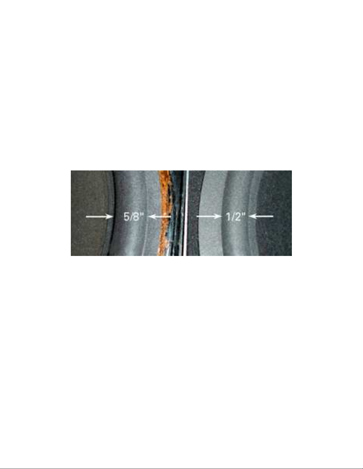
For foam-surround woofers: two options: purchase a do-it-yourself re-foaming kit, or have it
done professionally. Many amateurs re-foam and re-cone their own woofers. Sources for kits and
references to professionals can be found by searching old AR posts on The Classic Speaker
Pages at http://www.classicspeakerpages.net. Some re-foam kit sellers have posted DIY
instructions on their web sites. Two roll diameters, the widely available 1/2-in. (12.5 mm)diameter and the authentic 5/8-in. (16 mm)-diameter made for AR-3a 12-in. woofers are shown
in Fig. 3.3. Damaged spiders must be professionally replaced. Cloth-surrounds can be re-glued
where loose.
Fig. 3.3. Images of the authentic 5/8-in.- and 1/2-in.-diameter half-roll surround.
3.4 Removing the Stuffing
The first task before working on the inside of the cabinet is to remove the stuffing. Most AR-3a
cabinets were stuffed with yellow fiberglass; some were stuffed with rock wool. Both materials
are itchy and dusty. Rubber gloves and a dust mask are recommended. Work in a well-ventilated
area, preferably outside. Remove the fiberglass very carefully, noting how it was placed inside
the cabinet. Put the exact amount you removed in plastic bags; label the cabinet from which it
came. Set aside where the cat cannot disturb it until it is time for re-assembly. It will be reinstalled as closely as possible as it was originally installed. The weight and amount of this
material is important to the performance of the speaker. There will be some of the material down
around the coils, capacitors and level controls, so remove this also; later it will be re-installed in
the same manner. After completely removing the fiberglass, wash hands and face in cold water.
Cold water causes skin pores to close and reduce the amount of glass fiber that can become
entrapped on your skin. It is very important that you either sketch the internal wiring of each
cabinet, or take a close-up picture of the cabinet inside should you have any questions later.
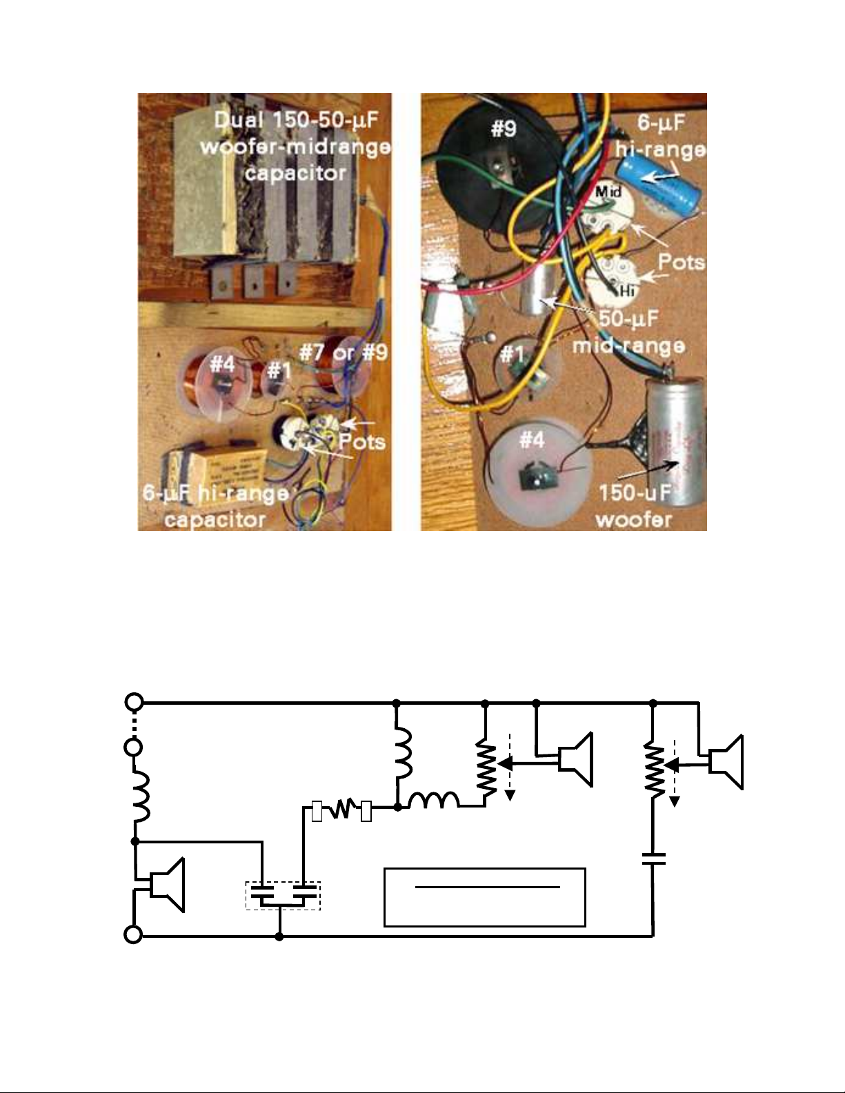
3.5 What’s Inside?
The physical layout of the crossover components is shown in Fig. 3.4 for the early and late
models of the AR-3a. (The early models had serial numbers up to about 38,000–39,000.)
Restoring the AR-3a 2007 The Classic Speaker Pages
10
Fig. 3.4. AR-3a Crossover circuitry: (Left) early circuit used from 1967–1969, (Right) late crossover
circuit used from 1970–1975.
The internal components are mounted on the crossover board and wired according to the
diagram shown in Fig. 3.5. The “crossover circuit,” or internal speaker wiring, divides the
frequency spectrum into three ranges and routes the appropriate range to each of the three drivers.
+
T
M
yellow
hi pot
16 Ω,
25 W
green
6 µF
blue
2
1
+
B
black
max.
volume
T
2
+
AR #9
inductor
2.85 mH
black
+
W
150 µF
1
-
blue
AR #4
inductor
0.88 mH
0.51 Ω
20 W
green
50 µF
mid pot
16 Ω,
25 W
AR #1
inductor
0.04 mH
“White Dot” Settings
Mid-range: R
Hi-range: R
B→→→→1
2
1
B→→→→1
yellow
+
B
green
= 3-1/4 Ω
= 1-3/4 Ω
Fig. 3.5. The early AR-3a factory-wired crossover circuit. The later circuit used individual 150- and 50-
µF capacitors; their common “blue” wire shown here existed only in the early crossover.
 Loading...