

Page 1
AR-3 Crossover Schematics 2008 The Classic Speaker Pages
AR-3 Crossover Schematics
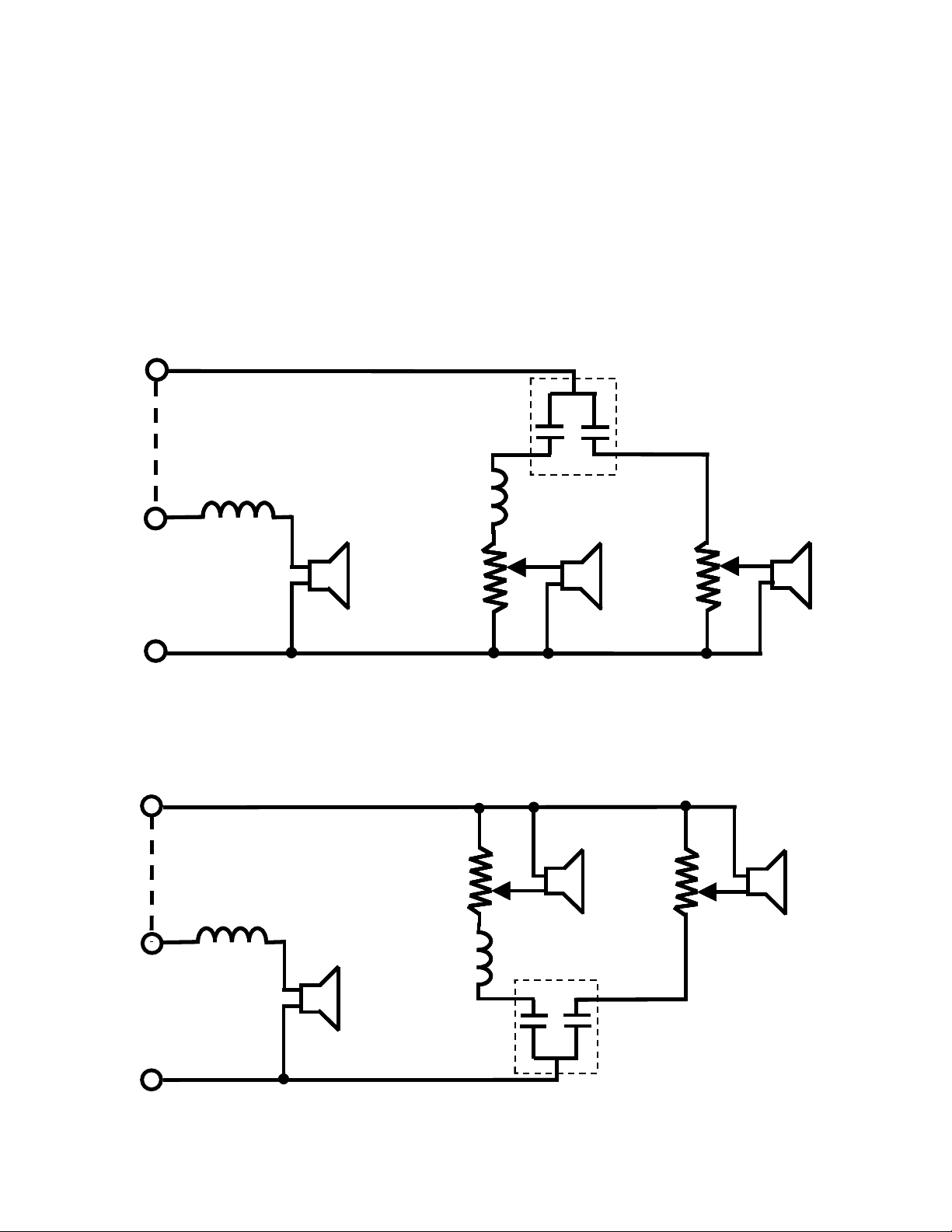
During its production cycle, AR modified the AR-3 crossover schematic several times. This note
attempts to catalog those changes based on detailed information available in Tom Tyson’s files.
At some point a complete description of the AR-3 will be written [TT]; at that time this should
become an appendix within that document.
A. Initial production through serial number C1413:
The schematic shown here; dated 13 March 1959 and initialed by EMV, is the original AR-3.
BE
T
T
BE
6 µF (dual capacitor)
6 µF (dual capacitor)
BK
BK
1
1
BK
BK
16 Ω
4500
4500
16 Ω
B
B
2
2
Y
Y
+
+
T
TT
375
375
2
2
1
1
STRAP
STRAP
0.4 mH
0.4 mH
R
R
BK
BK
+
+
W
WW
3700
3700
24 µF
24 µF
0.06 mH
0.06 mH
16 Ω
16 Ω
GN
GN
1
1
BK
BK
+
+
M
B
B
2
2
Y
Y
MM
B. Serial numbers C1414 – C19467:
In 1960 the crossover was changed to reverse the phase of the mid-range and tweeter with
respect to the woofer [1]. This was the only change made at this point in production.
T
T
4500 375
4500 375
M
MM
+
+
16 Ω
16 Ω
1
1
2
2
Y
Y
B
B
BK
BK
T
TT
+
+
STRAP
STRAP
0.4 mH
0.4 mH
16 Ω
16 Ω
2
2
1
1
B
B
BK
BK
Y
Y
2
2
R
R
+
+
W
WW
BK
BK
1
1
3700
3700
0.06 mH
0.06 mH
24 µF
24 µF
GN
GN
1
BE
BE
BK
BK
6 µF (dual capacitor)
6 µF (dual capacitor)
Page 2
AR-3 Crossover Schematics 2008 The Classic Speaker Pages
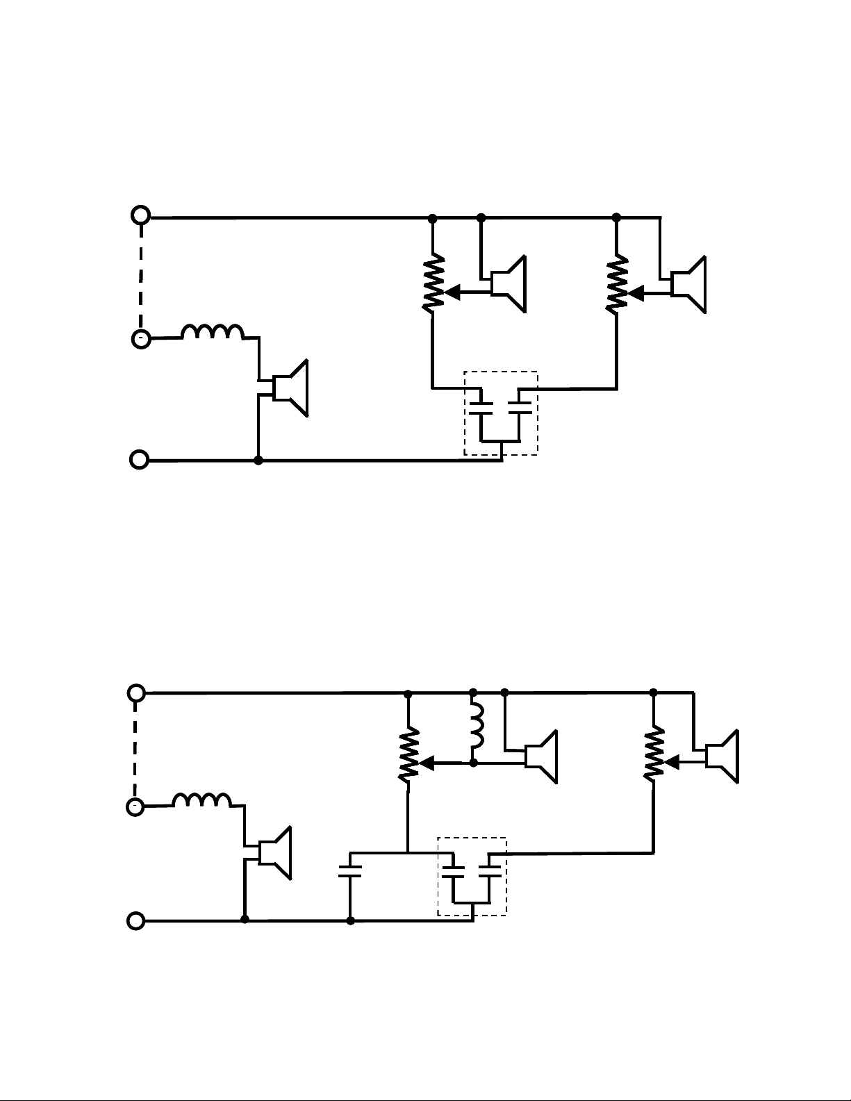
C. Serial numbers C19468 – C70228:
The crossover was modified on 25 Aug. 1965 by removing the 0.06-mH (51-turn) coil in the
mid-range crossover.
T
T
4500 375
4500 375
M
MM
+
+
+
+
6 µF (dual capacitor)
6 µF (dual capacitor)
16 Ω
16 Ω
BK
BK
BK
BK
2
2
2
2
1
1
Y
Y
Y
Y
B
B
BK
BK
T
TT
+
+
+
+
2
2
1
1
STRAP
STRAP
STRAP
STRAP
0.4 mH
0.4 mH
R
R
BK
BK
+
+
+
+
W
W
WW
WW
3700
3700
3700
3700
16 Ω
16 Ω
2
2
1
1
GN
GN
24 µF
24 µF
B
B
BK
BK
Y
Y
BE
BE
BE
BE
D. Serial numbers C70229 to end of production:
On 13 May 1970, AR ran out of the original phenolic-dome mid-range. This required the use of a
version of the AR-3a mid-range identified by part number 4500-3MOD and later identified as
part number 200010-AR-3 or 200019-3. (These are Fig’s. A.9 and A.10, respectively, in
Restoring the AR-3a.) This required a crossover change, as the AR-3 and AR-3a did not have the
same woofer–mid-range crossover frequency. This crossover change consisted of the addition of
a 6-µF capacitor in parallel with the 24-µF (to make a total of 30 µF) and the addition of a 0.4mH (143-turn) coil across the mid-range driver. These changes are illustrated below.
T
T
Y
2
2
1
1
STRAP
STRAP
0.4 mH
0.4 mH
BK
BK
0.4 mH
0.4 mH
Y
16 Ω
M
MM
+
+
4500-3Mod
4500-3Mod
BK
BK
6 µF (dual capacitor)
6 µF (dual capacitor)
16 Ω
1
1
2
2
B
1
1
GN
GN
24 µF
24 µF
B
BK
BK
BE
BE
16 Ω
16 Ω
3700
3700
R
R
+
+
W
WW
6 µF
6 µF
Y
Y
2
2
B
B
BK
BK
T
TT
+
+
375
375
2
Page 3
AR-3 Crossover Schematics 2008 The Classic Speaker Pages
E. Replacing the AR-3 mid-range with a service replacement:
After the original mid-range supplies were exhausted, the new driver described in Section D was
used for both production and service replacement. So it is possible that an Internet-purchased
speaker contains a service replacement mid-range. Service replacement was not straightforward,
as the crossover had to be changed to that shown in Section D. Thus, speakers with serial
numbers of C19467 and lower needed to have their 51-turn coil removed before the parts for the
new service replacement were added. Speakers with serial numbers greater than C70228 would
not have needed the crossover modification, since the new style mid-range was installed when
originally assembled.
F. Replacing the AR-3 high-range driver:
If an open-circuited, early high-range driver was not replaced with a new unit, then its
connections needed to be reversed to keep the correct phase relationship with the new mid-range
and woofer. By 1974 AR was supplying high range drivers with the phase reversed internally
and they were connected as the older models were, with no external reversal of the wiring. These
drivers all used aluminum wire; aluminum solder and flux, or crimp connections are required.
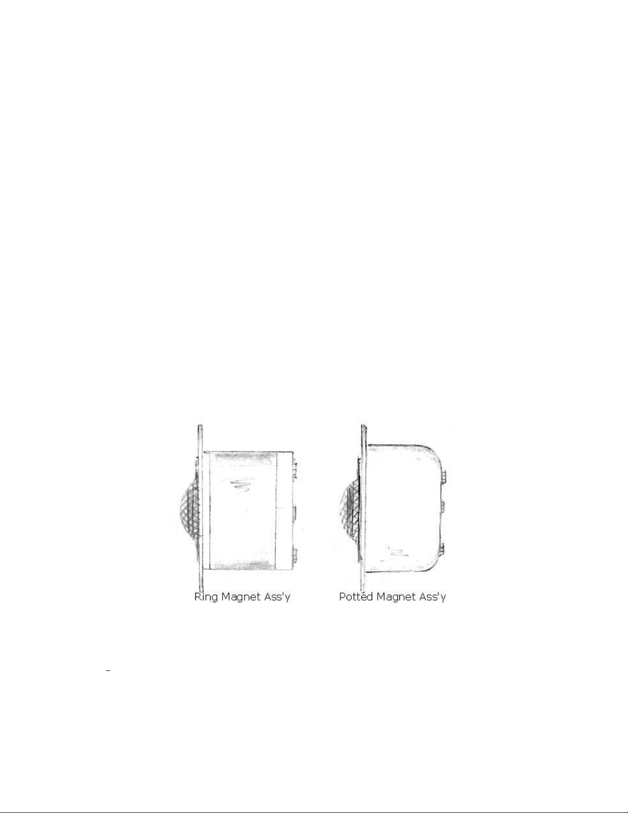
G. Mid-range Magnet Structure:
At some point in the 30,xxx serial number range, AR changed the magnet structure from the
modified form of the AR-1W, to a potted type magnet. The two cross-sectional views are shown
here. These two styles are equivalent.
H. A Potentially Confusing Schematic:
In the AR Library under [original models (1954-1974)] [schematics/service]
[AR-3] will be found a drawing entitled: AR-3 Schematic with Notes. This is not an AR-3
schematic! It is the schematic AR used at the factory to convert a customer’s AR-3 to an AR-3a! That
change required new mid-range and hi-range drivers, as well as all coils, and all except one of the
capacitors.
3
Page 4

AR-3 Crossover Schematics 2008 The Classic Speaker Pages
[1] Phase reversal was initially done manually by reversing the midrange/tweeter wiring with
respect to the woofer. At some point, AR either reversed magnet polarization or internal coil
wiring to change this phase internally. It is a daunting task to determine whether or not a
particular AR-3 is in-phase or out-of-phase. The acoustically measured effect is only slightly
noticeable and only barely audible—not to a great extent. Quite frankly, room-acoustic
artifacts can have a much greater influence on the output of the AR-3 than the simple dc
phasing reversal. If your AR-3 has never been opened or modified or repaired, it is almost
assured that the dc phasing is correct for that speaker, so do not worry about attempting to
change it. On the other hand, if a replacement driver of unknown pedigree was installed, then
all bets are off. In order to determine exactly the phase relationship, the speaker must be
electrically measured with a sine-wave oscillator and oscilloscope or with response
measurements at the crossover frequencies, but this is quite difficult to determine accurately
without professional test equipment. In the end, its probably best not to worry about the
phasing. If the speaker sounds too bright around the midrange crossover frequency (around
1000 Hz), and it is noticeable, you may reverse the lead-in wires from the midrange driver to
the terminal strip (thus reversing the polarity of the midrange driver on the tweeter terminal
strip on the front speaker baffle board under the grill). Since nearly all AR-3s used
aluminum wire from the tweeters, soldering the aluminum lead-in pigtails requires AlumiSol
aluminum solder to properly bond, so care must be used when unsoldering and re-soldering
to insure a proper solder joint. An alternative technique for joining aluminum to copper by a
crimp connection is described in the AR restoration document.
08 July 2008; John O’Hanlon, Tom Tyson
4
 Loading...