


RMC 7152
14” short depth server
14” short depth server
User Manual
RMC7152:14”shortdepthserverwith twoIntelXeon processors
1
|
© Copyright 2011 Acnodes, Inc. |
14628 Central Blvd, |
All rights reserved. Product description and product specifications |
Chino, CA91710 |
are subject to change without notice. For latest product information, |
tel:909.597.7588, fax:909.597.1939 |
please visit Acnodes’ web site at www.acnodes.com. |

RMC 7152
About This Manual
14” short depth server
15-inch touch panel PC
TheinformationinthisUser’sManualhas beencarefullyreviewedandisbelievedtobeaccurate.Thevendor assumes no responsibility for any inaccuracles that may be contained in this document, makes no commitment to update or to keep current the information in this manual, or to notifythat person or organization of the updates. Please Note: For the most up-to-date version of this manual, please see our website at www.acnodes.com.
Acnodes Corp. reserves the right to make changes to the product described in this manual at anytime and without notice. This product, including software, if any, and documentation may not, in whole or in part, be copied, photocopied,reproduced,translatedorreducedtoanymedium ormachinewihtoutpriorwrittenconsent.
INNOEVENWILLACNODESBELIABLEFORDIRECT,INDIRECT,SPECIAL,INCIDENTAL,SPECULATIVEOR CONSEQUENTIALDAMAGESARISINGFROMTHEUSEORINABILITYTOUSETHISPRODUCTORDOCUMENTATION,EVENIFADVISEDOFTHEPOSSIBILITYOFSUCHDAMAGES. INPARTICULAR,ACNODES CORPSHALLNOTHAVELIABILITTYFORANYHARDWARE,SOFTWARE,ORDATASTOREDORUSEDWITH THEPRODUCT,INCLUDINGTHECOSTSOFREPAIRING,REPLACING,INTEGRATING,INSTALLINGORRECOVERINGSUCHHARDWARE,SOFTWARE,ORDATA.
Anydisputes arising between maufacturer and customer shall be governed bythe laws of Walnut in the State of California,USA.TheStateof California,Walnutshallbethe exclusivevenuefor theresolutionof anysuchdisputes.Acnodes’total liabilityfor all claims will not exceed the price paid for the hardware product.
FCC Statement: This equipment has been tested and fount to complywith the limits for a ClassAdigital device pursuanttoPart15of theFCCRules. Theselimitsaredesignedtoprovidereasonableprotectionagainstharmful interferencewhentheequipmentisoperatedinacommercialenvironment. Thisequipmentgenerates,uses,and canradiateradio frequencyenergy,andif notinstalledandused inaccordancewiththe maufacturer’s instruction manual,maycauseharmfulinterferencewithradiocommunications. Operationof thisequipmentinaresidential area is likelyto cause harmful interference, in which case you would be required to correct the interference at your ownexpense.
CaliforniaBestManagementPracticesRegulationsfor PerchlorateMaterials.
This manualis writtenfor professionalsystem integratorsandPCtechnicials. Itprovides informationfor the installationanduseof theRMC7152. Installationandmaintenanceshouldbeperformedbyexperiencedtechnicians only.
TheRMC7152isa1Urackmountserver.Pleaserefertoourwebsiteforupdates onsupportedprocessors.
2
|
© Copyright 2011 Acnodes, Inc. |
14628 Central Blvd, |
All rights reserved. Product description and product specifications |
Chino, CA91710 |
are subject to change without notice. For latest product information, |
tel:909.597.7588, fax:909.597.1939 |
please visit Acnodes’ web site at www.acnodes.com. |

RMC 7152
14” short depth server
14” short depth server
Manual Organization
ManualOrganization
Chapter 1: Introduction
The firstchapter provides achecklist of themain components includedwith the server system and describes the main featuresoftheSuperX8DTL-iserverboardandtheSC811TQ-520Bchassis.
Chapter 2: Server Installation
This chapter describes the steps necessaryto install the RMC 7152 into a rack and check out the server configuration prior topowering upthesystem.If your server was ordered withouttheprocessor and memorycomponents,this chapter willrefer you to the appropriate sections of the manual for their installation.
Chapter 3: System Interface
Refer tothis chapter for details on the system interface,which includes the functions and information provided bythe control panel on the chassis as well as other LEDs located throughout the system.
Chapter 4: System Safety
Youshouldthoroughlyfamiliarizeyourselfwiththischapterforageneraloverviewof safetyprecautionsthatshouldbefollowed wheninstallingandservicingtheRMC7152.
Chapter 5: Advanced Serverboard Setup
Chapter5providesdetailedinformationontheX8DTL-iserverboard,includingthelocationsandfunctions ofconnectors, headersandjumpers.Refertothischapterwhenaddingor removingprocessorsormainmemoryandwhenreconfiguringthe serverboard.
Chapter 6: Advanced Chassis Setup
RefertoChapter6fordetailedinformationontheSC811TQ-520Bchassis.Youshouldfollowtheproceduresgiveninthis chapterwheninstalling,removingorreconfiguringSerialATAorperipheraldrivesandwhenreplacingsystem powersupply units and cooling fans.
Chapter 7: BIOS
TheBIOSchapter includes anintroductionto BIOSandprovides detailedinformationonrunningthe CMOSSetupUtility.
AppendixA: BIOS Error Beep Codes
Appendix B: Installing Windows
Appendix C: System Specifications
3
|
© Copyright 2011 Acnodes, Inc. |
14628 Central Blvd, |
All rights reserved. Product description and product specifications |
Chino, CA91710 |
are subject to change without notice. For latest product information, |
tel:909.597.7588, fax:909.597.1939 |
please visit Acnodes’ web site at www.acnodes.com. |

RMC 7152
14” short depth server
15-inch touch panel PC
CHAPTER1 INTRODUCTION
1.1 Overview
TheAcnodes RMC7152 is a 1Urackmount server designed for optimalspace efficiency.The RMC7152is comprisedof twomainsubsystems:theSC811TQ-520B1UchassisandtheX8DTL-iserverboard.Pleaserefertoourwebsiteforinforma- tion on operatingsystems that have beencertified for use withthe RMC 7152.
Inadditiontothemainboardandchassis,varioushardwarecomponents mayhavebeenincludedwiththeRMC7152,as listedbelow.
-TwopassiveCPUheatsinks
-Oneslim DVD-ROMdrive
-OneminiIDEtoSATAadapter forDVD-ROMdrive
-Two10-cm blowerfans
-Oneairshroud
-SAS/SATAAccessories:
OneinternalSAS/SATAbackplane
TwoSATAcables
OneSGPIO cable
TwoSATAdrivecarriers
-OnePCI-Express risercard
-Rackmounthardwarewithscrews
-OneCDcontainingdrivers andutilities
-RMC7152User'sManual
Note: "B" indicates black.
4
|
© Copyright 2011 Acnodes, Inc. |
14628 Central Blvd, |
All rights reserved. Product description and product specifications |
Chino, CA91710 |
are subject to change without notice. For latest product information, |
tel:909.597.7588, fax:909.597.1939 |
please visit Acnodes’ web site at www.acnodes.com. |

RMC 7152
14” short depth server
14” short depth server
1.2 Serverboard Features
TheX8DTL-iisadualprocessorserverboardbaseduponIntel's5500+ICH10Rchipset.Belowarethemainfeaturesofthe X8DTL-i.
Processor
TheX8DTL-isupportssingleordualtwoIntel®5500Series processorsinLGA1366sockets.Pleaserefer toour websiteforacompletelistingofsupportedprocessors(www.Acnodes.com).
Memory
TheX8DTL-ihas six240-pinDIMMslots thatcansupportupto24GBofECCregisteredDDR3-1333/1066/800 SDRAM.
Serial ATA
Anon-chip(ICH10R)SATAcontrollerisintegratedintotheX8DTL-itoprovideasix-port,3Gb/secSATAsub- system,whichis RAID0,1,5 and10supported.The SATAdrives arehot-swappable units.For moreinformation onSATA HostRAIDconfi guration,pleaserefer to theIntelSATAHostRAIDUser's Guide postedonour website athttp:// www.Acnodes.com/support/manuals.
Note:You must have RAID set up to enable the hot-swap capabilityof the SATAdrives.
PCI Expansion Slots
The X8DTL-i has two PCI Express 2.0 x8 slots, one PCI Express 2.0 x4 slot, one PCI Express x4 slot and two PCI 33 MHz slots. The PCI-E x8 (in a x16 slot) may be populated with a riser card (included).
Backpanel Ports
Onboard I/O backpanel ports include one COM port, a VGA port, two USB ports, PS/2 mouse and keyboard ports andtwoGigabitLAN(NIC)ports.
Other Features
Other onboard features that promotesystem health include voltage monitors, a chassis intrusion header, autoswitching voltage regulators, chassis and CPU overheat sensors, virus protectionand BIOS rescue.
5
|
© Copyright 2011 Acnodes, Inc. |
14628 Central Blvd, |
All rights reserved. Product description and product specifications |
Chino, CA91710 |
are subject to change without notice. For latest product information, |
tel:909.597.7588, fax:909.597.1939 |
please visit Acnodes’ web site at www.acnodes.com. |

RMC 7152
14” short depth server
15-inch touch panel PC
6
|
© Copyright 2011 Acnodes, Inc. |
14628 Central Blvd, |
All rights reserved. Product description and product specifications |
Chino, CA91710 |
are subject to change without notice. For latest product information, |
tel:909.597.7588, fax:909.597.1939 |
please visit Acnodes’ web site at www.acnodes.com. |

RMC 7152
1-3 Server Chassis Features
14” short depth server
14” short depth server
TheRMC7152 is builtonthe1Urackmount server chassis.Thefollowingis ageneraloutlineof themain features of the chassis.
System Power
For the RMC 7152, the chassis includes a single 520W power supply.
SerialATASubsystem
Thechassis wasdesignedtosupporttwoSATAharddrives.TheSATAdrivesarehot-swappableunits.
Note:The operating system you use must have RAID support to enable the hotswap capabilityof the SATAdrives.
ControlPanel
Thecontrolpanelprovidesimportantsystem monitoringandcontrolinformation.LEDsindicatepoweron,network activity, hard disk drive activityand system overheat conditions. The control panel also includes a main power button and a system resetbutton.
RearI/OPanel
The rear I/O panel accommodates one expansion card slot, one COM port (another is internal),two USB ports, PS/2 mouse and keyboard ports, a graphics port and two Gb Ethernet ports.
Cooling System
Thechassis has aninnovativecoolingdesignthatfeatures two10-cm blower system coolingfans.Theblower fans plugintoa chassis fan header on the serverboard.Afan speed control setting in BIOS allows fan speed to be determined bysystem temperature.
1.4 Contacting Acnodes
HEADQUARTERS
Address: |
AcnodesCorp. |
|
661BreaCanyonRd. |
|
Walnut,CA91789 |
Tel: |
(909)598-7388 |
Fax: |
(909)598-0218 |
Email: |
info@acnodes.com |
Website: |
www.acnodes.com |
7
|
© Copyright 2011 Acnodes, Inc. |
14628 Central Blvd, |
All rights reserved. Product description and product specifications |
Chino, CA91710 |
are subject to change without notice. For latest product information, |
tel:909.597.7588, fax:909.597.1939 |
please visit Acnodes’ web site at www.acnodes.com. |

RMC 7152
14” short depth server
15-inch touch panel PC
CHAPTER2
2.1 Overview
This chapter provides a quick setup checklist to get your RMC 7152 up and running. FOllowing the steps in the order given should enable you to have the system operational within a minimal amount of time. This quick setup assumes that your system has come to you with the processor and memory preinstalled. If your system is not already fully integrated with a serverboard, processor, system memoryetc., please turn to the chapter or section noted in each step for details on installing specificcomponents.
2.2 Unpacking the System
You should inspect the box the server was shipped in and note if it was damaged in anyway. If the server itself shows damage,youshould fileadamageclaim withthecarrier who deliveredit.
Decide on a suitable location for the rack unit that will hold the server. It should be situated in a clean, dust-free area that is wellventilated.Avoid areas whereheat,electrical noseandelectromagnetic fields are generated.Youwillalso needitplaced near agrounded power outlet.Readtherack andserver precations in thenextsection.
2.2 Preparing for Setup
The RMC 7152 does not ship with a rack rail hardware package as the system can be rack mounted without the use of rails. An optional rack rail package is available if you wish to order fromAcnodes. Follow the steps in the order given to complete the installation process in a minimal amount of time. Please read this section in its entirety before you begin the installation procdeureoutlined inthe sections that follow.
8
|
© Copyright 2011 Acnodes, Inc. |
14628 Central Blvd, |
All rights reserved. Product description and product specifications |
Chino, CA91710 |
are subject to change without notice. For latest product information, |
tel:909.597.7588, fax:909.597.1939 |
please visit Acnodes’ web site at www.acnodes.com. |
RMC 7152
14” short depth server
14” short depth server
2.4 Installing the System into a Rack
This section provides information on installing the RMC 7152 into a rack. If the system has already been mounted into a rack, you can skip ahead to Sections 2-5 and 2-6.
There are a varietyof rack units on the market, which maymean the assemblyprocedure will differ slightly.The following is a guideline for installing the unit into a rack with the rack rails provided with the system. You should also refer to the installation instructions that came with the rack unit you are using.
Basic Installation Procedure
You should have received two rack rail assemblies with the RMC 7152. Each of these assemblies consist of two sections: an inner fixed chassis rail that secures to the unit (A) and an outer fi xed rack rail (B) that secures to the rail brackets.Asliding rail guide sandwiched between the two should remain attached to the fixed rack rail (see Figure 2-1).TheAand B rails must be detached from each other to install.
To remove the fixed chassis rail (A), pull it out as far as possible - you should hear a "click" sound as a locking tab emerges from inside the rail assembly and locks the inner rail. Then depress the locking tab to pull the inner rail completely out. Do this for both the left and right side rack rail assemblies.
Figure 2-1. Identifying the Sections of the Rack Rails
9
|
© Copyright 2011 Acnodes, Inc. |
14628 Central Blvd, |
All rights reserved. Product description and product specifications |
Chino, CA91710 |
are subject to change without notice. For latest product information, |
tel:909.597.7588, fax:909.597.1939 |
please visit Acnodes’ web site at www.acnodes.com. |
RMC 7152
Installing the Chassis Rails
14” short depth server
15-inch touch panel PC
Position the fixed chassis rail sections you just removed along the side of the chassis making sure the five screw holes line up. Note that these two rails are left/right specific. Screw the rail securely to the side of the chassis (see Figure
2-2). Repeat this procedure for the other rail on the other side of the chassis. You will also need to attach the rail brackets when installing into a telco rack.
Locking Tabs:As you have seen, both chassis rails have a locking tab, which serves two functions. The first is to lock the server into place when installed and pushed fully into the rack, which is its normal position. Secondly, these tabs also lock the server in placewhenfullyextended from therack.This prevents theserver from comingcompletelyout of therack whenyou pullit outfor servicing.
10
|
© Copyright 2011 Acnodes, Inc. |
14628 Central Blvd, |
All rights reserved. Product description and product specifications |
Chino, CA91710 |
are subject to change without notice. For latest product information, |
tel:909.597.7588, fax:909.597.1939 |
please visit Acnodes’ web site at www.acnodes.com. |
RMC 7152
Installing the Rack Rails
14” short depth server
14” short depth server
Determine where you want to place the RMC 7152 in the rack (see Rack and Server Precautions in Section 2-3). Position the fixed rack rail/sliding rail guide assemblies at the desired location in the rack, keeping the sliding rail guide facing the inside of the rack. Screw the assembly securely to the rack using the brackets provided.Attach the other assembly to the other side of the rack, making sure that both are at the exact same height and with the rail guides facing inward.
Installing the Server Into the Rack
You should now have rails attached to both the chassis and the rack unit. The next step is to install the server into the rack. Do this by lining up the rear of the chassis rails with the front of the rack rails. Slide the chassis rails into the rack rails, keeping the pressure even on bothsides (you mayhave to depress the locking tabs when inserting). See Figure 2-3.
When the server has been pushed completely into the rack, you should hear the locking tabs "click".
11
|
© Copyright 2011 Acnodes, Inc. |
14628 Central Blvd, |
All rights reserved. Product description and product specifications |
Chino, CA91710 |
are subject to change without notice. For latest product information, |
tel:909.597.7588, fax:909.597.1939 |
please visit Acnodes’ web site at www.acnodes.com. |
RMC 7152
Installing the Server into a Telco Rack
14” short depth server
15-inch touch panel PC
If you are installing the RMC 7152 into aTelco type rack, followthe directions given on the previous pages for rack installation. The onlydifference in the installation procedure will be the positioning of the rack brackets to the rack. Theyshould be spaced apart just enough to accomodate the width of the telco rack.
12
|
© Copyright 2011 Acnodes, Inc. |
14628 Central Blvd, |
All rights reserved. Product description and product specifications |
Chino, CA91710 |
are subject to change without notice. For latest product information, |
tel:909.597.7588, fax:909.597.1939 |
please visit Acnodes’ web site at www.acnodes.com. |

RMC 7152
2.5 Checking the Serverboard Setup
14” short depth server
14” short depth server
After you install the server in the rack, you will need to open the unit to make sure the serverboard is properly installed and all theconnectionshavebeenmade.
Removing the Chassis Cover
1.Release the retention screws that secure the unit to the rack.
2.Grasp the two handles on either side and pull the unit straight out until it locks (you will hear a “click”)
3.Removethescrewsfrom therearlipof thechassiscover(Seefigure2-5)
4.Release the top cover by pushing it away from you until it stops. You can then lift the top cover from the chassis to gain full acccess to the inside of the server.
Checking the Components
1.You mayhave processors alreadyinstalledin theserverboard. Eachprocessor shouldhave its ownheatsink attatched.
2.The RMC 7152 server mayhave come with the system memoryalreadyinstalled. Make sure all DIMMs are fullyseated in their slots.
3.If desired, you can install an add-on card to the system.
4.Make sure all power and data cables are properlyconnected and not blocking the airflow.
2.6 Checking the Drive Bay Setup
Next,you shouldcheck tomake surethe peripheraldrives and theSATAdrives have beenproperlyinstalledand allessential connectionshavebeenmade.
CheckingtheDrives
-ForservicingtheDVD-ROMandfloppydrives,youwillneedtoremovethetopchassis cover.
-TheSerialATAdisk drives canbeinstalledandremovedfrom thefrontof thechassiswithoutremovingthetop chassiscover.
-Dependingupon your system's configuration, your system mayhave oneor two SerialATAdrives alreadyinstalled. If you need to install SerialATAdrives.
CheckingtheAirflow
-Airflowis provided bytwo 10-cm input fans.The system component layout was carefullydesigned to promote sufficientairflowthroughthesmall1Urackmountspace.
-Also note that all power and data cables have been routed in such a waythat they do not block the airflow generated by the fans.
ProvidingPower
-The last thing you must do is to provide input power to the system. Plug the power cord from the power supplyunit intoahigh-qualitypower stripthatoffersprotectionfrom electricalnoiseandpower surges.
-It is recommended that youuse an uninterruptible power supply(UPS).
13
|
© Copyright 2011 Acnodes, Inc. |
14628 Central Blvd, |
All rights reserved. Product description and product specifications |
Chino, CA91710 |
are subject to change without notice. For latest product information, |
tel:909.597.7588, fax:909.597.1939 |
please visit Acnodes’ web site at www.acnodes.com. |
RMC 7152
CHAPTER3 SYSTEM INTERFACE
14” short depth server
15-inch touch panel PC
3.1 Overview
There areseveral LEDs on thecontrol panel as wellas others on theSATAdrive carriers tokeep you constantlyinformedof the overall status of the system as well as the activityand health of specific components. There are also two buttons on the chassis control panel. This chapter explains the meanings of all LED indicators and the appropriate response you mayneed to take.
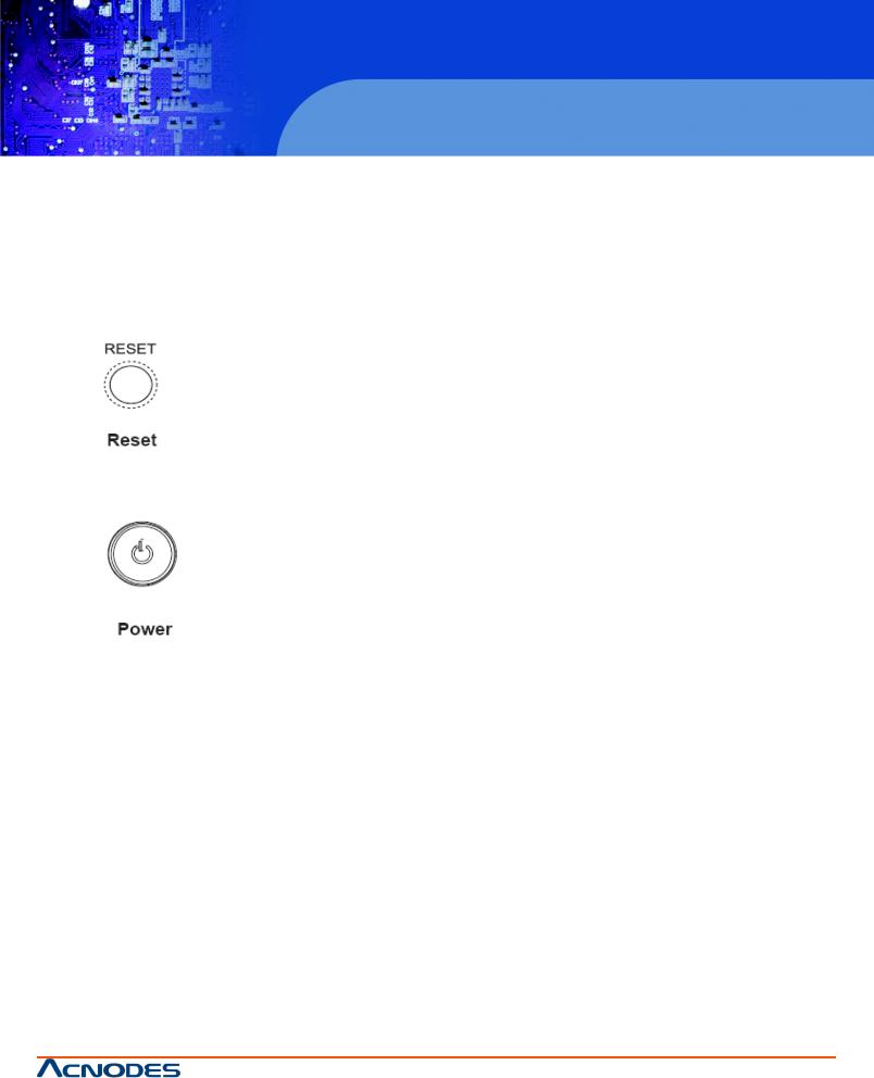
3.2 Control Panel Buttons
There aretwo push buttons located on thefront of thechassis: a resetbutton and apower on/offbutton.
The reset switch reboots the system
This is the main power switch, which is used to apply or turn off the main system power. Turning off system power with this button removes the main power but keeps the standbypower supplied to the system.
14
|
© Copyright 2011 Acnodes, Inc. |
14628 Central Blvd, |
All rights reserved. Product description and product specifications |
Chino, CA91710 |
are subject to change without notice. For latest product information, |
tel:909.597.7588, fax:909.597.1939 |
please visit Acnodes’ web site at www.acnodes.com. |
RMC 7152
14” short depth server
14” short depth server
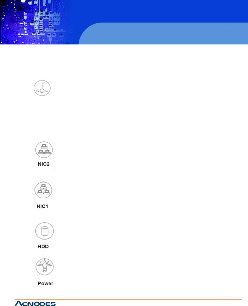
3.3 Control Panel LEDs
Thecontrolpanellocatedonthefrontof theRMC7150chassis has fiveLEDs.TheseLEDs provideyouwithcriticalinformation related to different parts of the system. This section explains what each LED indicates when illuminated and anycorrective action you may need to take.
Overheat/FanFail
When this LED flashes it indicates a fan failure. When on continiously(on and not flashing) it indicates an overheat condition, which maybe caused bycables obstructing the airflow in the system or the ambient room temperature being too warm. Check the routing of the cables and make sure all fans are present and operating normally. You should also check to make sure that the chassis covers are installed. Finally, verifythat the heatsinks are installed properly. This LED will remain flashing or on as long as the overheat condition exists.
Indicatesnetwork activityonLAN2whenflashing.
Indicatesnetwork activityonLAN1whenflashing.
ChannelactivityforHDDs.ThislightindicatesIDEdriveactivitywhenflashing.
Indicates power is being supplied to the system’s power supplyunits. This LED should normallybe illuminated when the
system is operating.
15
|
© Copyright 2011 Acnodes, Inc. |
14628 Central Blvd, |
All rights reserved. Product description and product specifications |
Chino, CA91710 |
are subject to change without notice. For latest product information, |
tel:909.597.7588, fax:909.597.1939 |
please visit Acnodes’ web site at www.acnodes.com. |

RMC 7152
14” short depth server
15-inch touch panel PC
3-4 Serial ATA Drive Carrier LEDs
EachSerialATAdrive has both agreen anda redLED.
-Green:EachSATAdrivecarrier has agreenLED.Whenilluminated,this greenLED(onthefrontoftheSATAdrive carrier) indicates drive activity.Aconnection to the SATAbackplane enables this LED to blink on and off when that particular driveisbeingaccessed.
-Red:The redLED toindicate anSATAdrivefailure. If one of the SATAdrives fail,you shouldbe notifiedbyyour system managementsoftware.PleaserefertoChapter6for instructionsonreplacingfailedSATAdrives.
16
|
© Copyright 2011 Acnodes, Inc. |
14628 Central Blvd, |
All rights reserved. Product description and product specifications |
Chino, CA91710 |
are subject to change without notice. For latest product information, |
tel:909.597.7588, fax:909.597.1939 |
please visit Acnodes’ web site at www.acnodes.com. |

RMC 7152
CHAPTER 4 SYSTEM SAFETY
4.1 Electrical Safety Precautions
14” short depth server
14” short depth server
Basic electricalsafetyprecautions shouldbefollowedtoprotect yourself from harm andthe RMC7152damage:
-Be aware of the locations of the power on/off switch on the chassis as well as the room’s emergencypower on/off switch, disconnection switch or electrical outlet. If an electrical accident occurs, you can then quicklyremove power from the system.
-Donotwork alonewhenworkingwithhighvoltagecomponents.
-Power should always be disconnected from the system when removing or installing main system components, suchastheserverboard,memorymodulesandfloppydrive.Whendisconnectingpower,youshouldfirstpowerdownthe system with the operating system first and then unplug the power cords of all the power supply units in the system.
-AWhenworkingaroundexposedelectricalcircuits,anotherpersonwhoisfamiliar withthepower-offcontrols should be neaerbyto switch off the power if necessary.
-Useonlyonehand whenworking withpowered-on electrical equipment.This is to avoidmaking acomplete circuit, which will cause electrical shock. use extreme caution when using metal tools, which can easily damage any electrical components or circuit boards they come into contact with.
-Do not use mats designed to decrease static electrical discharge as protection from electrical shock. Instead, use rubber mats that have beenspecificallydesigned as electrical insulators.
-Thepower supplypower cords must includeagroundingplugand mustbepluggedinto groundedelectricaloutlets.
-This product may be connected to an IT power system. In all cases, make sure that the unit is also relably connected to Earth.
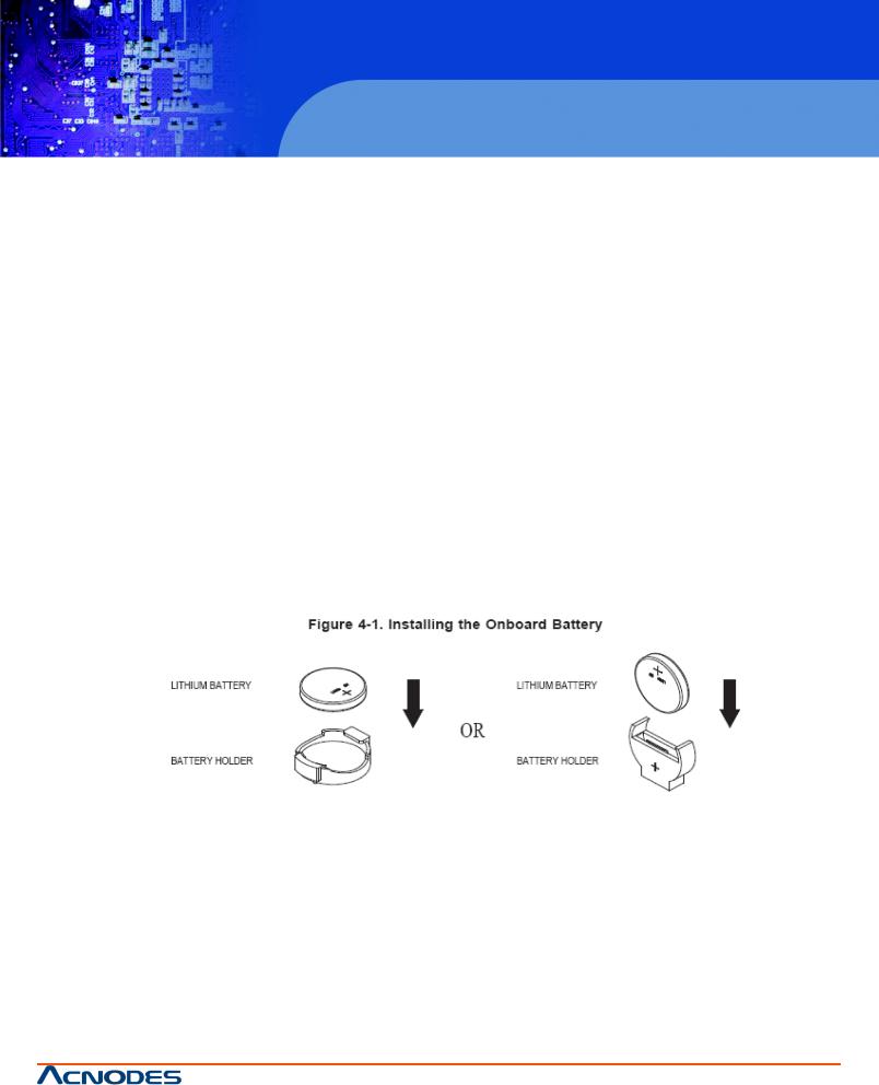
-ServerboardBattery:CAUTION-Thereisadangerof explosioniftheonboardbatteryisinstalledupsidedown, which will reverse its polarities. This batterymust be replaced onlywith the same or an equivalent type recommended bythe manufacturer.Disposeof usedbatteriesaccordingtothemanufacturer’sinstructions.
-DVD-ROMLaser:CAUTION-ThisservermayhavecomeequippedwithaDVD-ROMdrive.Topreventdirect exposuretothe laser beam andhaardous radiationexposure,donot opentheenclosureor usetheunitin anyunconventional way.
-Mainboardreplaceablesoldered-infuses:Self-resettingPTC(PositiveTemperatureCoefficient)fusesonthe mainboardmust bereplacedbytrained servicetechnicians only.The newfusemust bethesameor equicalentservice technicians only.The new fuse must be the same or equivalend as the one replaced. Contact technical support for details andsupport.
4.2General Safety Precautions
Followtheserules to ensuregeneral safety:
-KeeptheareaaroundtheRMC7152andfreeof clutter.
-The RMC 7152 weighs approximately18 lbs. when fullyloaded. When lifting the system, two people at either end should lift slowly with their feet spread out to distribute the weight.Always keep your back straight and lift with your legs.
-Place the chassis top cover and anysystem components that have been removed awayfrom the system or on a table so that they won’t accidentally be stepped on.
-Remove anyjewelryor metal objects from your body, which are excellent metal conductors that can create short circuits and harm you if theycome into contact with printed circuit boards or areas where power is present.
-After accessing the inside of the system, close the system back up and secure it to the rack unit with the retention
screwsafterensuringthatallconnectionshavebeenmade.
17
|
© Copyright 2011 Acnodes, Inc. |
14628 Central Blvd, |
All rights reserved. Product description and product specifications |
Chino, CA91710 |
are subject to change without notice. For latest product information, |
tel:909.597.7588, fax:909.597.1939 |
please visit Acnodes’ web site at www.acnodes.com. |
RMC 7152
4.3 ESD Precautions
14” short depth server
15-inch touch panel PC
Electrostatic Discharge (ESD) is generated bytwo objects with different electrical charges coming into contact with each other. An electrical discharge is created to neutralize this difference, which can damage electronic components and printed circuit boards.Thefollowingmeasures aregenerallysufficienttoneutralizethisdifferencebeforecontactis madetoprotectyour equipmentfrom ESD:
-Use agrounded wriststrapdesigned toprevent static discharge.
-Keep all components and printed circuit baords (PCDs) in their antistatic bag.
-Do not let components or PCBs come into contact with your clothing, which may retain a charge even if you are wearing awrist strap.
-Handle a board by its edges only; do not touch its components, peripheral chips, memory modules or contacts.
-Whenhandlingchips or modules,avoidtouchingtheir pins.
-Put the serverboard and peripherals back into their antistatic bags when not in use.
-For groudingpurposes,makesureyour computerchassis provides excellentconductivitybetweenthepower supply, thecase,themountingfastenersandtheserverboard.
4.4Operating Precautions
Care must be taken to assure that the chassis cover is in place when it is operating to assure proper cooling. Out of warranty damage to the system can occur if this practice is not strictly followed.
18
|
© Copyright 2011 Acnodes, Inc. |
14628 Central Blvd, |
All rights reserved. Product description and product specifications |
Chino, CA91710 |
are subject to change without notice. For latest product information, |
tel:909.597.7588, fax:909.597.1939 |
please visit Acnodes’ web site at www.acnodes.com. |

RMC 7152
14” short depth server
CHAPTER5ADVANCED SERVERBOARD SETUP
14” short depth server
This chapter covers the steps required to install the serverboard into the chassis, connect the data and power cables and installadd-oncards.Allserverboardjumpers andconnections arealsodescribed.Alayoutandquick referencechartare included inthis chapter for your reference.Remember to completelyclose the chassis when youhave finished workingwith the serverboard tobetter cool and protectthe system.
5.1 Handling the Serverboard
Electrostatic Discharge (ESD) can damage electronic components. To prevent damage to anyprinted circuit boards (PCBs),itis importanttohandlethem verycarefully(seeprevious chapter).Topreventtheserverboardfrombend-ing,keepone handunderthecenterof theboardtosupportitwhenhandling.Thefollowingmeasures aregenerallysufficienttoprotectyour equipmentfrom electric static discharge.
Precautions
-UseagroundedwristwrapstrapdesignedtopreventESD.
-Touchagroundedmetalobjectbeforeremovinganyboardfrom its antistaticbag.
-Handle a board by its edges; do not touch its components, peripheral chips, memorymodules or gold contacts.
-Whenhandlingchips or modules,avoidtouchingtheir pins.
-Put the serverboard,add-on cards and peripherals back into their antistatic bags when not in use.
-Forgroundingpurposes,makesureyour computer chassis providesexcellentconductivitybetweenthepower supply, thecase,themountingfastenersandtheserverboard.
Unpacking
The serverboard is shippedinantistatic packagingtoavoidelectricalstatic discharge.Whenunpackingthe boardmakesure the person handling it is static protected.
5.2 Server Installation
This section explains the first step of physically mounting it into the chassis. Following the steps in the order given will eliminatemostcommonproblemsencounteredinsuchaninstallation.Toremovetheserverboard,followtheprocedureinreverse order.
Installing to the Chassis
1.Removethescrews from the rear lipof thechassis cover.
2.Release the top cover by pushing it away from you until it stops. You can then lift the top cover from the chassis to gain full access to the inside of the server.
3.Make sure that the I/O ports on the serverboard align properlywith their respective holes in the I/O shield at the back of the chassis.
4.Carefullymounttheserverboardtotheserverboardtraybyaligningtheboardholeswiththeraisedmetalstandoffsthatare visible to the chassis.
5.Insert screws into all the mounting holes on your serverboard that line up with the standoffs and tighten until snug.
19
|
© Copyright 2011 Acnodes, Inc. |
14628 Central Blvd, |
All rights reserved. Product description and product specifications |
Chino, CA91710 |
are subject to change without notice. For latest product information, |
tel:909.597.7588, fax:909.597.1939 |
please visit Acnodes’ web site at www.acnodes.com. |
RMC 7152
5.3 Connecting Cables
14” short depth server
15-inch touch panel PC
Now that the serverboard is installed, the next step is to connect the cables to the board. These include the data cables for the peripheralsandcontrolpanelandthepowercables.
ConnectingDataCables
Thecablesusedtotransferdatafrom theperipheraldeviceshavebeencarefullyroutedtopreventthem from blockingtheflowof cooling air that moves through the system from the back. If you need to disconnect anyof these cables, you should take care to keep them routed as theywere originallyafter reconnecting them.
Thefollowingdatacablesshouldbeconnected.
-DVD-ROMcable
-SATAdrivecables
-ControlPanelcable
ConnectingPowerCables
Ithas a24-pinprimarypower supplyconnector for connectiontotheATX power supply.Inaddition,therearetwo8-pinproces- sor connectors that also must be connected to your power supply.
20
|
© Copyright 2011 Acnodes, Inc. |
14628 Central Blvd, |
All rights reserved. Product description and product specifications |
Chino, CA91710 |
are subject to change without notice. For latest product information, |
tel:909.597.7588, fax:909.597.1939 |
please visit Acnodes’ web site at www.acnodes.com. |
RMC 7152
14” short depth server
14” short depth server
5.4 Rear I/O Ports
TheI/O ports arecolor codedinconformance withthePC 99specification.
21
|
© Copyright 2011 Acnodes, Inc. |
14628 Central Blvd, |
All rights reserved. Product description and product specifications |
Chino, CA91710 |
are subject to change without notice. For latest product information, |
tel:909.597.7588, fax:909.597.1939 |
please visit Acnodes’ web site at www.acnodes.com. |
 Loading...