

Page 1
SERVICE MANUAL
Model Name : PD100/PD100D/PD120/
PD120D/XD1170D/XD1270D
Prepared by SI :
________________________________________
Prepared by TSE :
________________________________________
Check by :
________________________________________
Approved by :
________________________________________
Date Revise Version Description
2005/8 V1.0 Initial Issue(PD100/PD100D/PD120/PD120D)
2006/7 V2.0 add XD1170D&1270D models, add pages 2/5/7/15/49/80-111
Copyright July, 2006 . All Rights Reserved
P/N#36.82V01G001 . Document#82V-G04-02A
Page 2

Preface
This manual is applied to Acer PD100 0.55 inch 120 DDR DMD SVGA Micro Portable
Projector / PD100D 0.55 inch 120 DDR DMD SVGA Micro Portable Projector / PD120 0.55
inch 120 DDR DMD SVGA Micro Portable Projector / PD120D 0.55 inch 120 DDR DMD SVGA
Micro Portable Projector / XD1170D 0.55 inch 120 DDR DMD SVGA Micro Portable Projector
/ XD1270D 0.55 inch 120 DDR DMD XGA Micro Portable Projector. The manual gives you a
brief description of basic technical information to help in service and maintaining the product.
Your customers will appreciate the quick response time when you immediately identify
problems that occur with our products. We expect your customers will appreciate the service
that you offer them.
This manual is for technicians and people who have an electronic background. Please
send the product back to the distributor for repairing and do not attempt to do anything that is
complex or is not mentioned in the troubleshooting.
NOTICE :
The information found in this manual is subject to change without prior notice. Any
subsequent cha nges made to the data herein will be incorporated in further edition.
PD100/PD100D/PD120/PD120D/XD1170D/XD1270D Service Manual
Copyright July, 2006
All Rights Reserved
Manual Version 2.0
Page 3

PD100 PD100D PD120 PD120D XD1170D XD1270D
Service Guide
Service guide files and updates are available
on the AIPG/CSD web; for more information,
please refer to http://csd.acer.com.tw
PRINTED IN TAIWAN
Page 4

Revision History
Please refer to the table below for the updates made on PD100, PD100D, PD120, PD120D, XD1170D, XD1270D service guide.
Date Chapter Updates
II
Page 5

Copyright
Copyright © 2006 by Acer Incorporated. All rights reserved. No part of this publication may be reproduced,
transmitted, transcribed, stored in a retrieval system, or translated into any language or computer language, in
any form or by any means, electronic, mechanical, magnetic, optical, chemical, manual or otherwise, without
the prior written permission of Acer Incorporated.
Disclaimer
The information in this guide is subject to change without notice.
Acer Incorporated makes no representations or warranties, either expressed or implied, with respect to the
contents hereof and specifically disclaims any warranties of merchantability or fitness for any particular
purpose. Any Acer Incorporated software described in this manual is sold or licensed "as is". Should the
programs prove defective following their purchase, the buyer (and not Acer Incorporated, its distributor, or its
dealer) assumes the entire cost of all necessary servicing, repair, and any incidental or consequential
damages resulting from any defect in the software.
Acer is a registered trademark of Acer Corporation.
Intel is a registered trademark of Intel Corporation.
Pentium 4 and Celeron are trademarks of Intel Corporation.
Other brand and product names are trademarks and/or registered trademarks of their respective holders.
III
Page 6

Conventions
The following conventions are used in this manual:
Screen messages
NOTE Gives bits and pieces of additional
WARNING Alerts you to any damage that might
CAUTION Gives precautionary measures to
IMPORTANT Reminds you to do specific actions
Denotes actual messages that appear
on screen.
information related to the current
topic.
result from doing or not doing specific
actions.
avoid possible hardware or software
problems.
relevant to the accomplishment of
procedures.
IV
Page 7

Preface
Before using this information and the product it supports, please read the following general information.
1. This Service Guide provides you with all technical information relating to the BASIC CONFIGURATION
decided for Acer's "global" product offering. To better fit local market requirements and enhance product
competitiveness, your regional office MAY have decided to extend the functionality of a machine (e.g.
add-on card, modem, or extra memory capability). These LOCALIZED FEATURES will NOT be covered
in this generic service guide. In such cases, please contact your regional offices or the responsible
personnel/channel to provide you with further technical details.
2. Please note WHEN ORDERING FRU PARTS, that you should check the most up-to-date information
available on your regional web or channel. If, for whatever reason, a part number change is made, it will
not be noted in the printed Service Guide. For ACER-AUTHORIZED SERVICE PROVIDERS, your Acer
office may have a DIFFERENT part number code to those given in the FRU list of this printed Service
Guide. You MUST use the list provided by your regional Acer office to order FRU parts for repair and
service of customer machines.
V
Page 8

Table of Contents
Chapter 1 System Introduction 1
Technical Specification 1
Product Overview 2
Chapter 2 Firware Upgrade 7
Equipment Needed 7
Installation Procedure 8
USB Driver Upgrade Procedure 10
Firmware Upgrade Procedure 12
EDID Upgrade 1 5
Equipment Needed 15
Setup Procedure 16
EDID Key-in Procedure 16
Chapter 3 Mechanical Disassembly and Reassembly 1 9
Equipment Needed 19
General Information 19
Mechanical Disassembly Procedure 20
Mechanical Reassembly Procedure 33
Chapter 4 Troubleshooting 46
Equipment Needed 46
LED Lighting Message 46
Main Procedure 47
Function Test and Alignment Procedure 4 9
Product / Test Equipment / Test Condition 49
Inspection Procecdure 50
Guide to Entering Service Mode and Factory Reset (PD100) 53
Chapter 5 Exploded Overview 54
Exploded Overview 54
Appendix Serial Number Definition System 112
I. Serial Number System Definition 112
II. PCBA Code Definition 113
III. The Different Parts (PD100 / PD100D / PD120 / PD120D / XD1170D /
XD1270D ) 114
IV. Identification Method for “D” Model 118
Page 9
System Introduction
Tec hnical Specification
Item Description
Dimensions (WxHxD) 230 x 122.8 x 238 mm
Tilt Angle 7 degree with elevator mechanism
Keystone correction +/-16 degree (32 degree) (Horizontal)
Lamp Door Projection Lamp power supply shut off automatically when door open
Universal AC 100-240V ~ 50-60Hz with PFC input
Power Supply
200W for Philips UHP Lamp @ normal operation
Variance FAN speed control
(Depends on temperature variant)
Chapter 1
Throw Distance
Contrast
Uniformity
Temperature
Maximum Humidity
Lamp Life
Altitude
MTBF Operating more than 12,000 hours (90% Confidence Level)
1.5m - 10m (Optical Performance)
1.5m - 12m (Mechanical Travel)
1000 : 1 Full White and Black (Minimum; Full Power Mode)
1800 : 1 Full White and Black (Typical; Full Power Mode)
75% Japan standard (Minimum; Full Power Mode)
85% Japan standard (Typical; Full Power Mode)
Opterating : 5~35oC
Storage : -20~60oC
Operating : 5~35oC, 80%RH (Max.), non-condensing
Storage : -20~60oC, 80%RH (Max.), non-condensing
1500 hours min, 50% survival rate (Full Power Mode)
2000 hours min, 50% survival rate (Eco Mode)
Operating : 0~2,500 ft for 5 oC~35oC
2,500~5,000 ft for 5 oC~30oC
5,000~10,000 ft for 5 oC~25oC
Storage : 40,000 ft (Max.)
1 Cha pter 1
Page 10
Tec hnical Specifica tion(PD1 00/PD100D/PD120/PD120D)
Item Description
Weight Approx. 4.85 lbs (2.2 Kg)
Projection Lens F#2.7~3.0, f=21.83mm~23.81mm, 1.10X Mechanical Zoom Lens
Brightness
Acoustic noise level
1700 ANSI Lumens (Typical; Full Power Mode)
1170 ANSI Lumens (Typical; Eco Mode)
38 dB(A) (Typical, Under 23 +/- 20C; Full Power Mode without
DVD/wireless)
30 dB(A) (Typical, Under 23 +/- 20C; Eco Mode without DVD/wireless)
Tec hnical Spe cification(XD1 170D)
Item Description
Weight Approx. 5.3 lbs (2.4 Kg)
Projection Lens F#2.35~2.47, f=21.83mm~23.81mm, 1.10X Mechanical Zoom Lens
Brightness
Acoustic noise level
1850 ANSI Lumens (Typical; Full Power Mode)
1450 ANSI Lumens (Typical; Eco Mode)
35 dB(A) (Typical, Under 23 +/- 20C; Full Power Mode without
DVD/wireless)
30 dB(A) (Typical, Under 23 +/- 20C; Eco Mode without DVD/wireless)
Tec hnical Spe cification(XD127 0D)
Item Description
Weight Approx. 4.85 lbs (2.2 Kg)
Projection Lens F#2.35~2.47, f=21.83mm~23.81mm, 1.10X Mechanical Zoom Lens
Brightness
Acoustic noise level
Cha pter 1 2
1850 ANSI Lumens (Typical; Full Power Mode)
1450 ANSI Lumens (Typical; Eco Mode)
35 dB(A) (Typical, Under 23 +/- 20C; Full Power Mode without
DVD/wireless)
30 dB(A) (Typical, Under 23 +/- 20C; Eco Mode without DVD/wireless)
Page 11
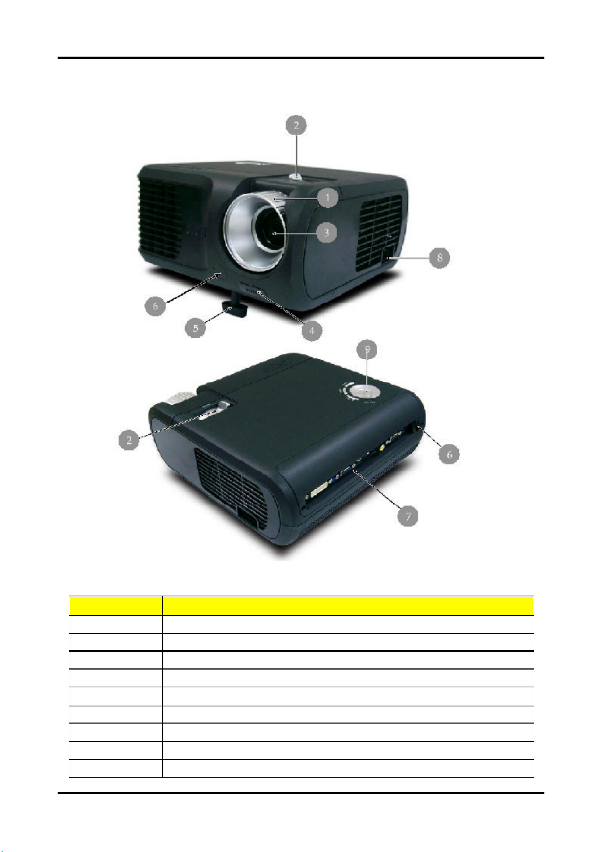
Pr oduct Overview
M ain Unit
Item Description
1 Focus Ring
2 Zoom Ring
3 Zoom Lens
4 Elevator Button
5 Elevator Foot
6 Remote Control Receiver
7 Connection Ports
8 Power Socket
9 Control Panel
3 Cha pter 1
Page 12
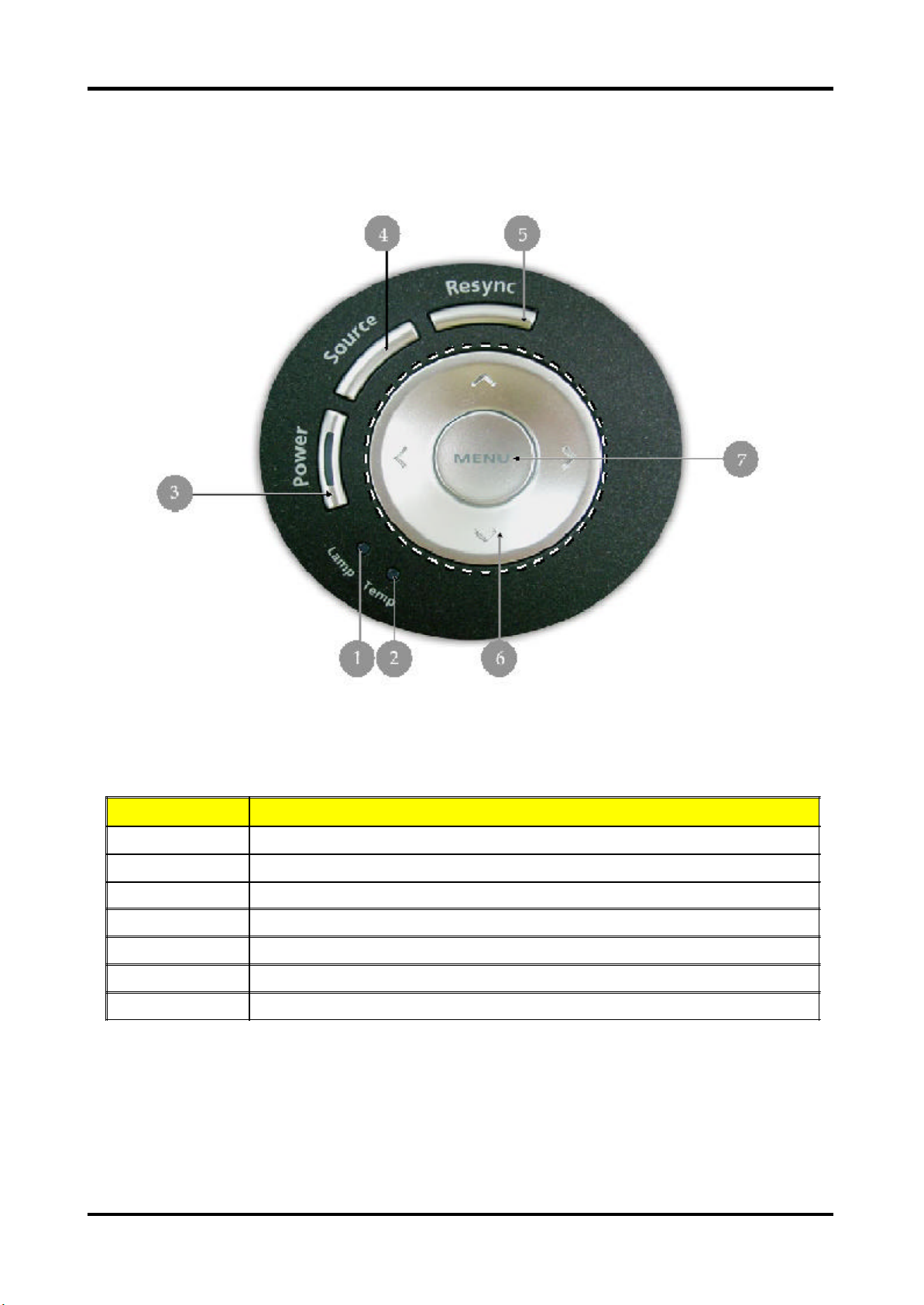
Control Panel
Item Description
1 Lamp Indicator LED
2 Temp Indicator LED
3 Power / Standby and Indicator LED (Power LED)
4 Source
5 Resync
6 Four Directional Select Keys
7 Menu
Cha pter 1 4
Page 13
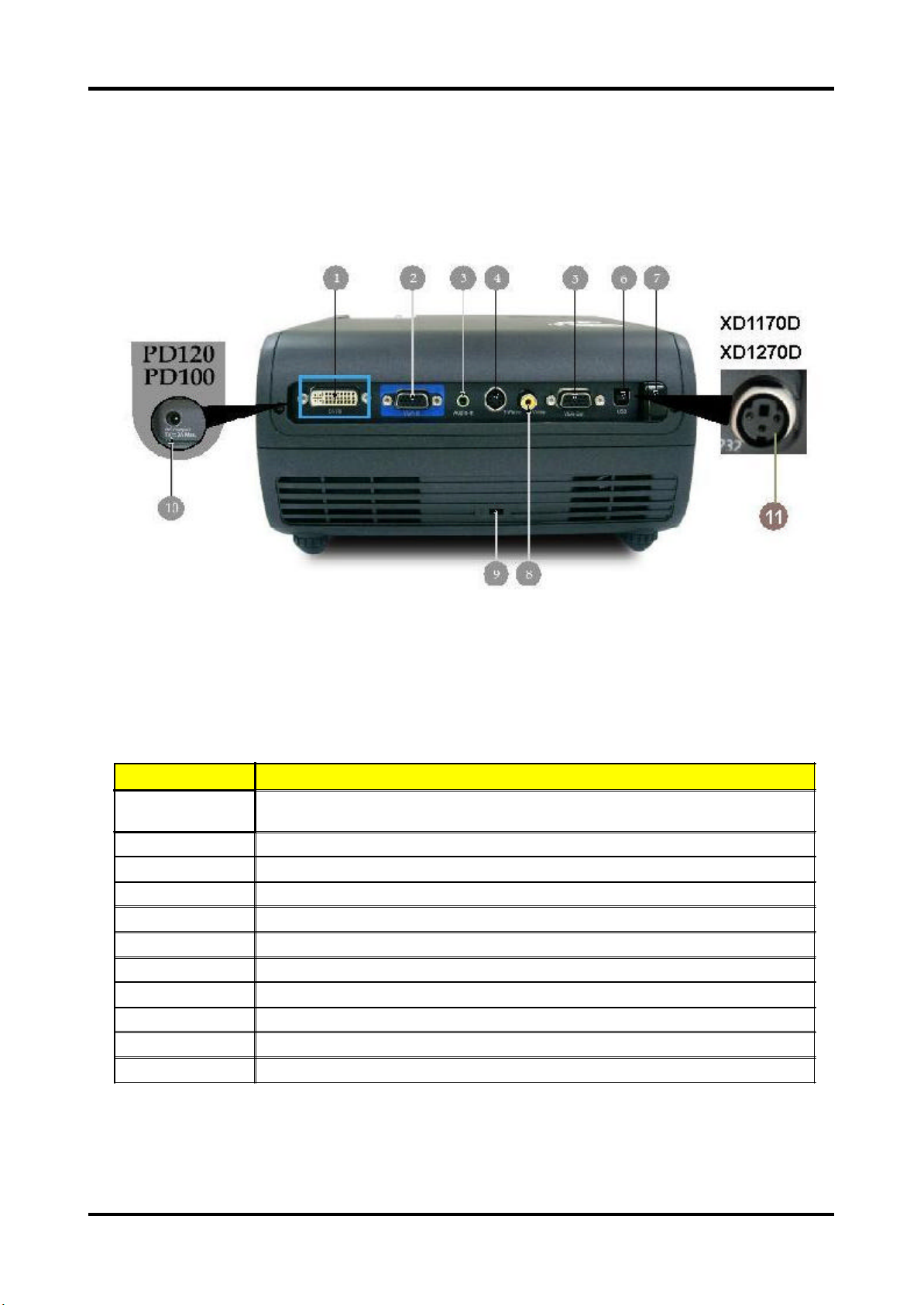
Connecti on Ports
Item Description
1
2 PC Analog Signal / HDTV / Component Video Input Connector
3 Audio Input Connector
4 S-Video Input Connector
5 Monitor Loop-through Output Connector
6 USB Connector
7 Remote Control IR Receiver (for PD100/PD100D/PD120/PD120D only)
8 Composite Video Input Connector
9 KensingtonTM Lock Port
10 5V DC Output Jack (dfor attached dongle device) (for PD100 only) (for PD120 only)
11 RS232 Connector (for XD1170D only) (for XD1270D only)
DVI Input Connector (for Digital signal with HDCP function)
(Optional)
5 Cha pter 1
Page 14
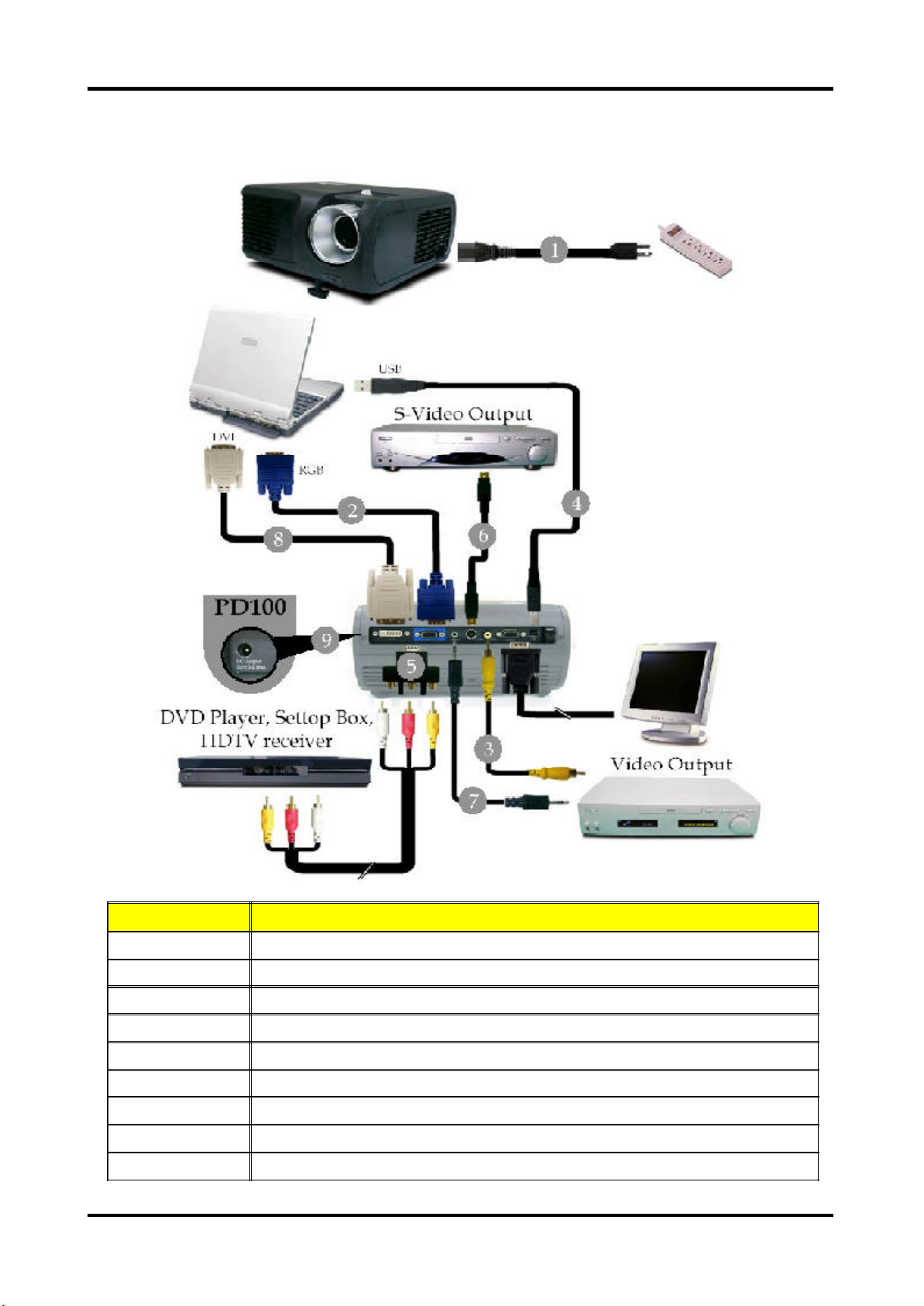
Connecting t he Projector
Item Description
1 Power Cord
2 VGA Cable
3 Composite Video Cable
4 USB Cable
5 VGA to Component / HDTV Adapter
6 S-Video Cable
7 Audio Cable Jack / Jack
8 DVI Cable (Optional Accessory)
9 5V DC Output Jack for attached Dongle Device (for PD100 only) (for PD120 only)
Cha pter 1 6
Page 15
Chapter 2
Firmware Upgrade
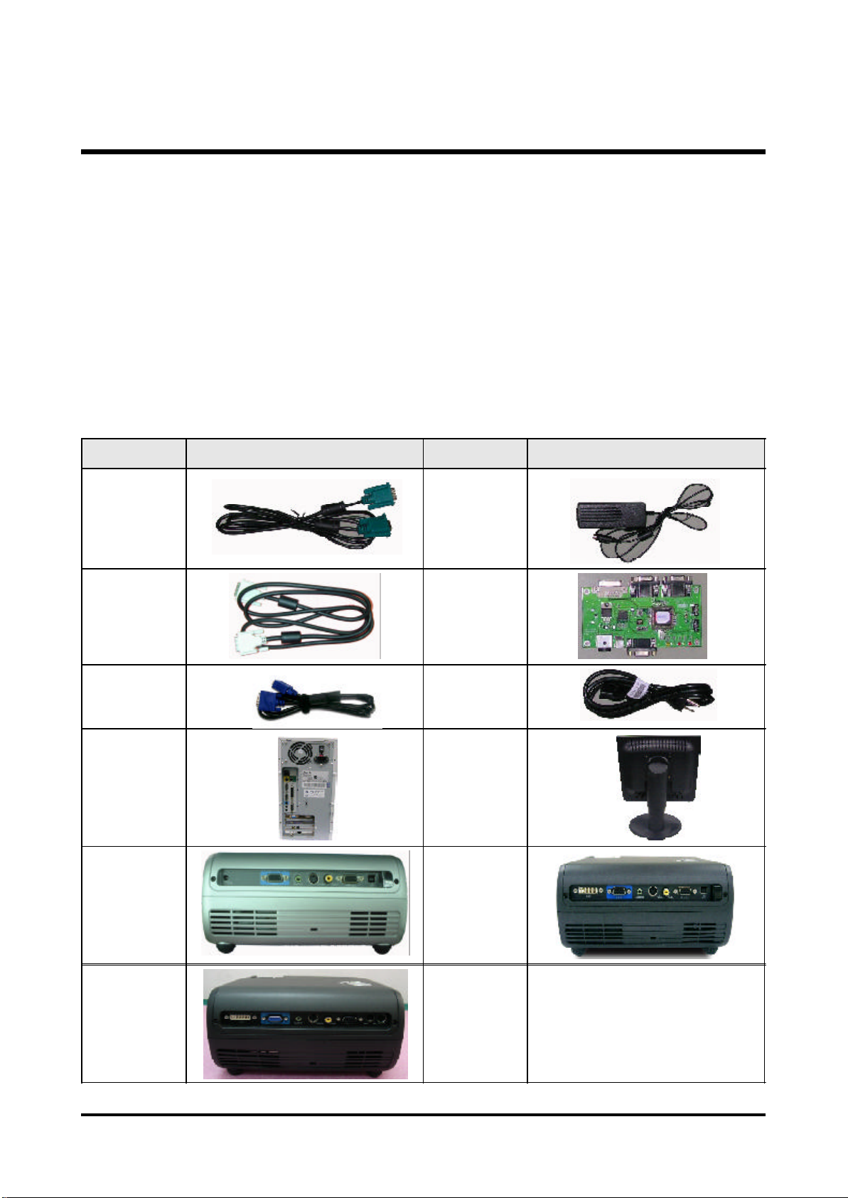
Equipment Needed
Software : (DDP 2000- USB)
- DLP Composer
- Firmware (PD100 /PD100D / PD120 / PD120D/XD1170D/XD1270D)
Hardware :
Item Photo Item Photo
Projector
(PD100 /
PD100D)
Power Cord
USB Cable PC or Laptop
Projector
(PD120 /
PD100D)
Projector
(XD1170D/XD1270D)
7 Cha pter 2
Page 16
Ins tallation Procedure
DLP Composer Lite Setup Procedure
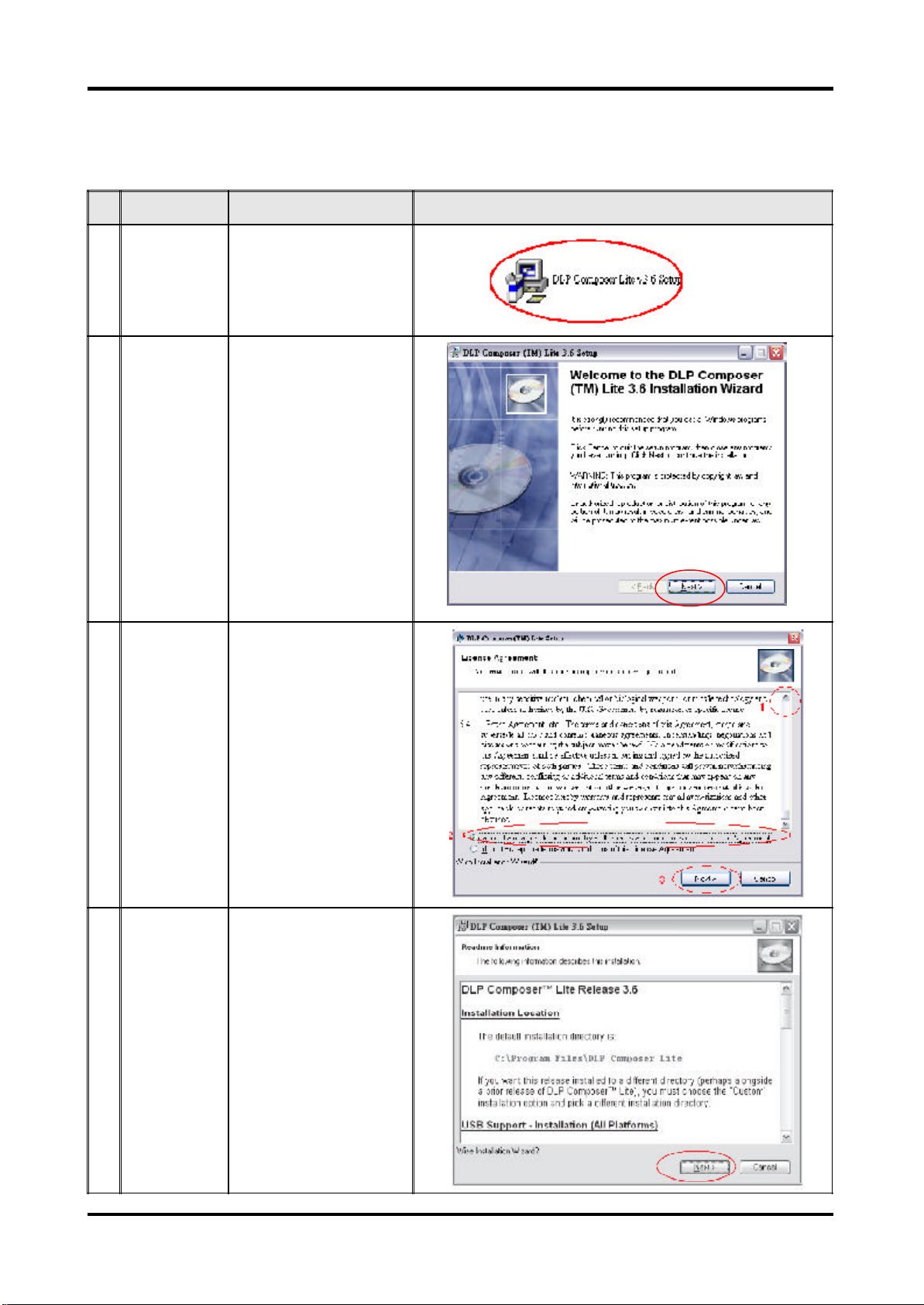
No Step Procedure Photo
1 Execute FW
program
2 Next Click "Next" button.
3 Next 1. Reading the "License
Choose "DLP Composer
Lite v3.6 Setup" program.
Agreement" rules.
2. Choose "I accept and
agree to be bound by all
the terms and conditions
of this License
Agreement" icon,
3. Click "Next" button.
4 Next Click ""Next"" button.
Cha pter2 8
Page 17
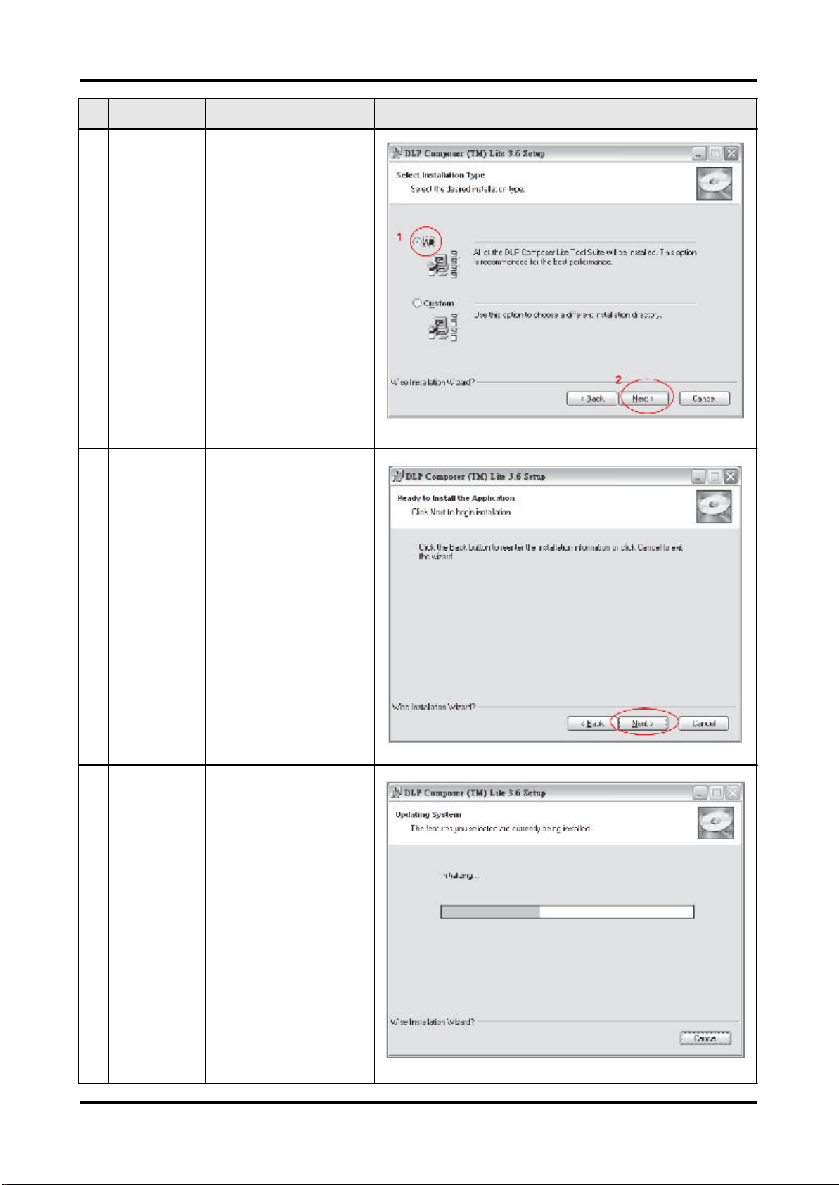
No Step Procedure Photo
5 Next 1. Choose "All" icon
2. Click "Next" button.
6 Next Click "Next" button.
7 Processing The program is executing
"Initializing" status.
9 Cha pter 2
Page 18
USB Driver Upgrade Procedure
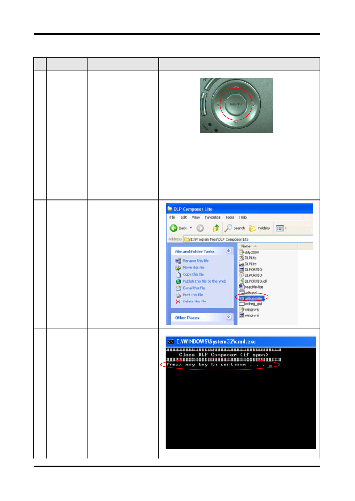
No Step Procedure Photo
1 Set-up 1. Plug in USB Cable into
the Projector.
2. Hold on "Menu" button
and then plug in Power
Cord.
3. Wait for about 5
seconds.
(Note: The system fan will
not function. The light will
not function as well.)
2 Execute
Program
3 Type any key to
continue
Execute the C:\Program
files\DLP
Composer\usbupdata.cmd.
(Note: The "DLP
Composer" program
must be closed first.)
Press any key to continue.
Then, wait for about 1
minute.
Cha pter2 10
Page 19
No Step Procedure Photo
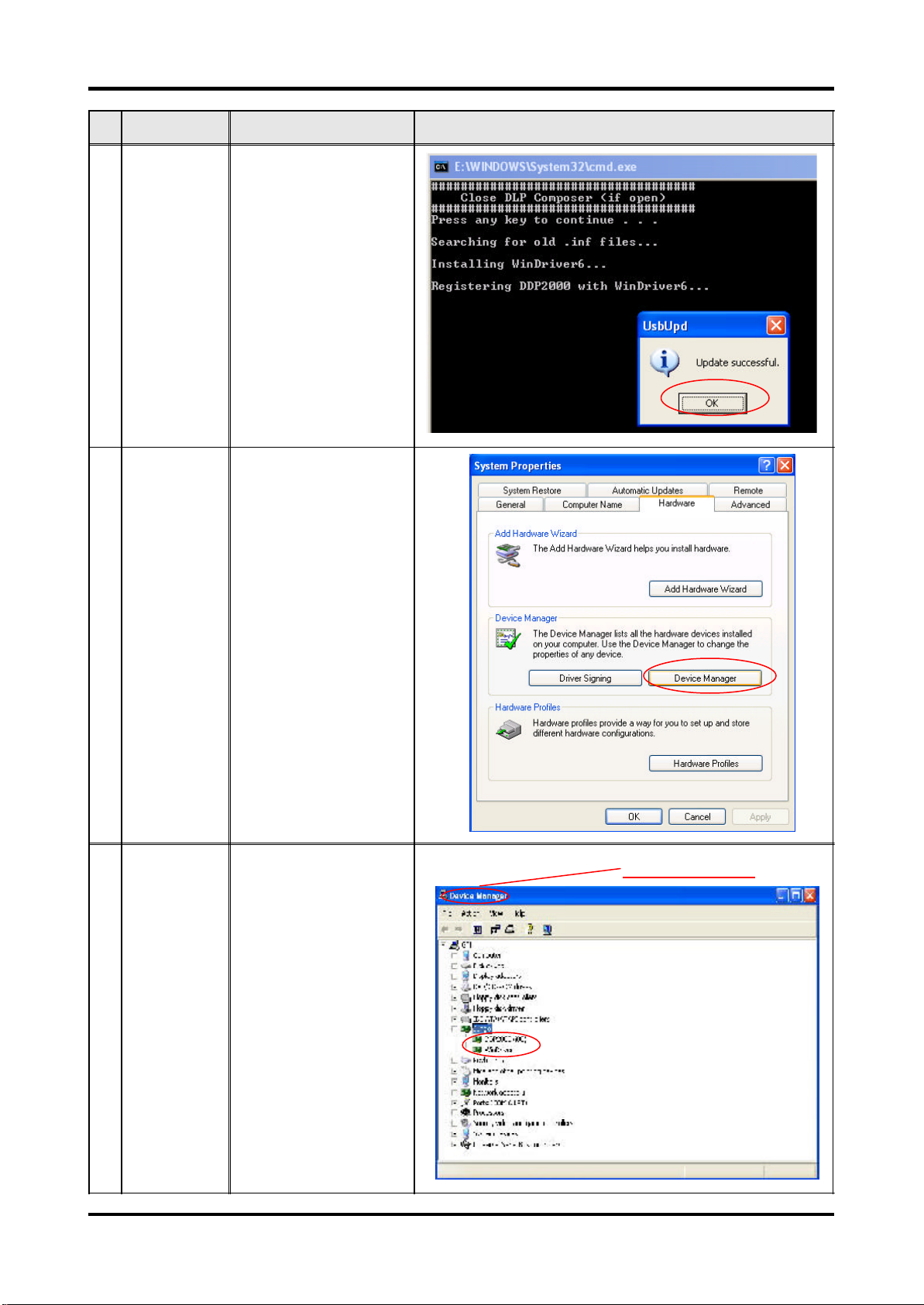
4 Update
Successfully
5 Device
Manager
Click "OK". The USB driver
is updated successfully.
1. Right click "My computer"
on the desktop.
2. Select "Properties" on
the popup menu to launch
the "System Properties"
window.
3. Choose "Hardware" and
then click "Device
Manager".
6 Ensure
"DDP2000" &
"WinDriver" are
properly
installed
Click "Jungo" to ensure
"DDP2000" and
"Windriver" are properly
installed. If not, repeart
Step 1~5.
Device Manager
11 Cha pter 2
Page 20
Fir mware Upgrade Pr ocedure
No Step Procedure Photo
1 Set-up 1. Plug in USB Cable into
the Projector.
2. Hold on "Menu" button
and then plug in Power
Cord.
3. Wait for about 5
seconds.
(Note: The system fan will
not function. The light will
not function as well.)
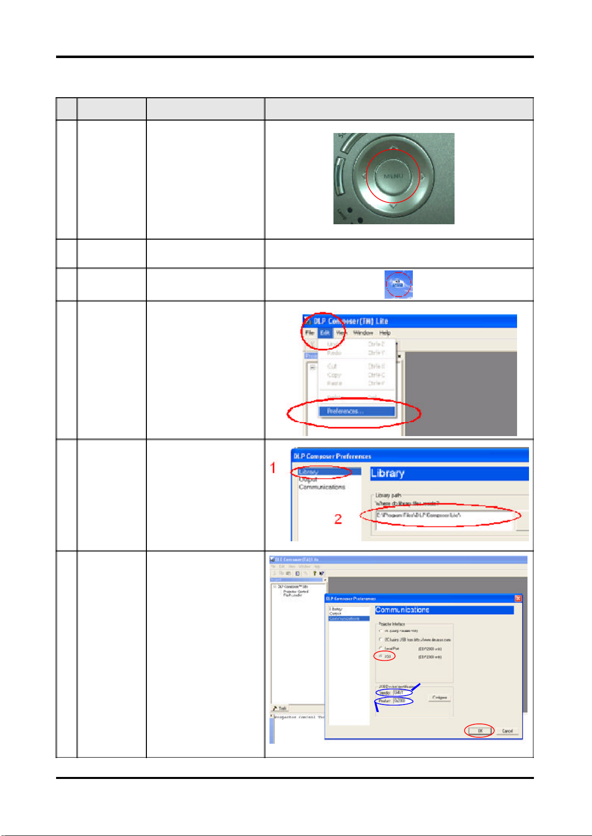
2 Set-up Link PC COM1 and
projector
3 Execute the "DLP
Compose
4 Click "Edit" and
"Preferences".
5 1. Click "Library".
2. The library path located
in the default installation
directory is:
C:\Program Files\DLP
Composer.
If not, press "Browse" to
select the right path.
6 1. Select
"Edit\Preferences\
Communications" and
choose "USB".
2. Click "OK".
TM"
file.
.
1
2
1
USB
Vendor: 0x451
Product: 0x2000
2
OK
Cha pter2 12
Page 21
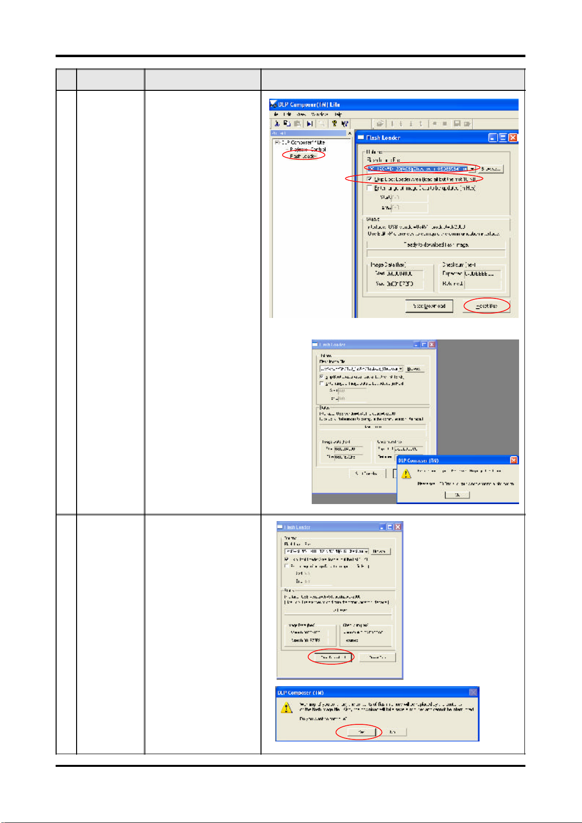
No Step Procedure Photo
7 1. Choose "Flash Loader"
2. Click "Browse" to search
the firmware file. (PD100
/ PD120)
3. Select the item "Skip
Boot Loader Area (load
all but the first 16KB)."
4. Click "Reset Bus" to
erase the flash memory.
(Note: If the error message
"cannot open USB driver No projectors found"
appears, please unplug the
USB Cable and replug,
then re-do 4. Click "Reset
Bus" to erase the flash
memory.)
1
2
3
Note:
4
8 1. If the firmware is ready,
click "Start Download" to
process the firmware
upgrade.
2. Click "Yes" to erase the
flash memory.
1
2
13 Cha pter 2
Page 22
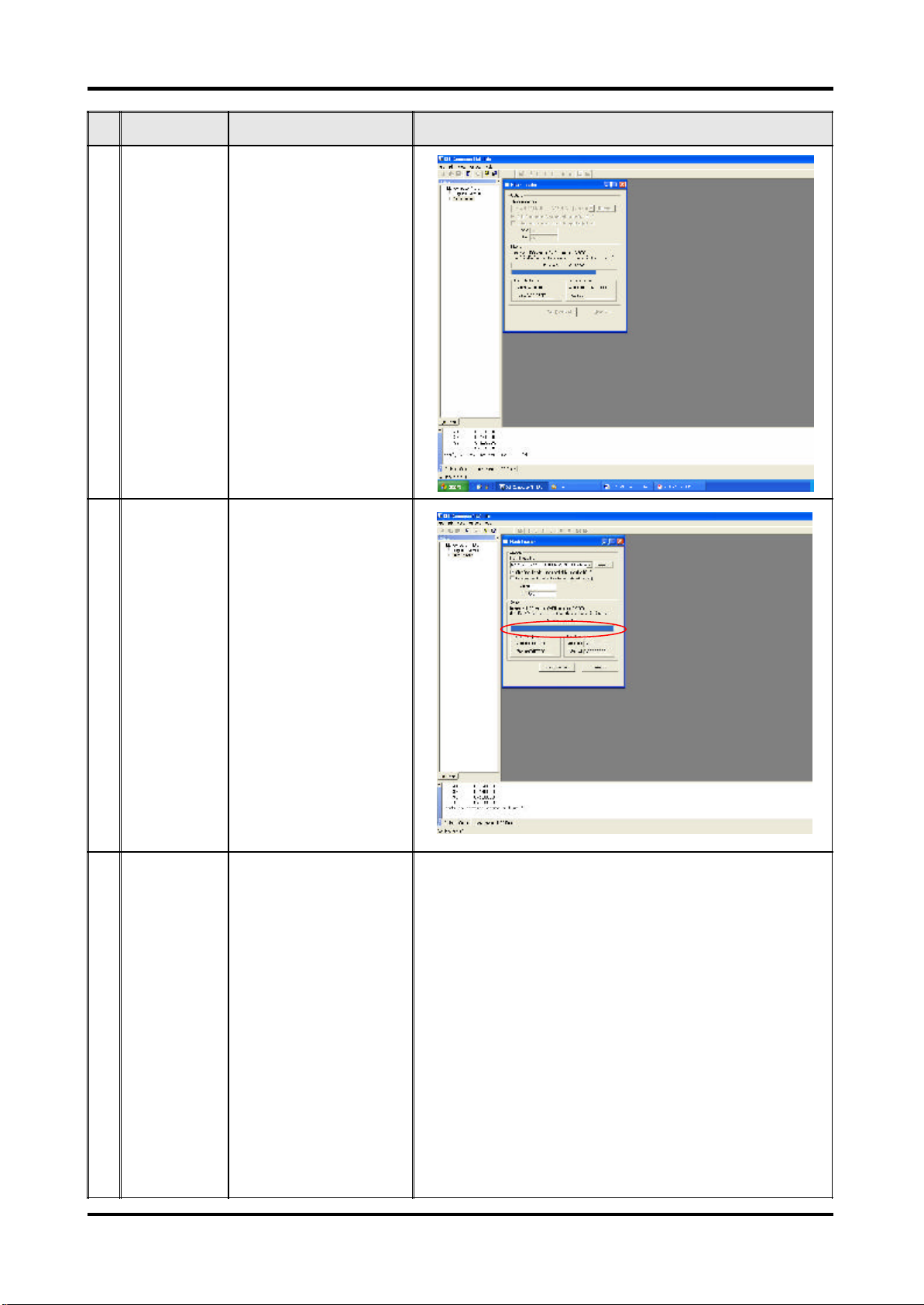
No Step Procedure Photo
9 Proceeding Proceeding Picture
10 1. When Firmware Upgrade
Process is finished, the
LED power
2. Unplug USB Cable and
Power Cord. Re-plug in
Power Cable after 3 mins.
11 Check
Firmware
Restart the unit and enter
the Service Mode to check
the Firmware Version.
(For entering Service
Mode, please refer to
Chapter 4 Function Test
and Alignment Procedure.)
Cha pter2 14
Page 23
EDI D Upgrade
Equipment Needed
Software:
- EDI D Key-in Program
- EDI D Program (Generic V0.51)
- EDI D Table (*.ini)
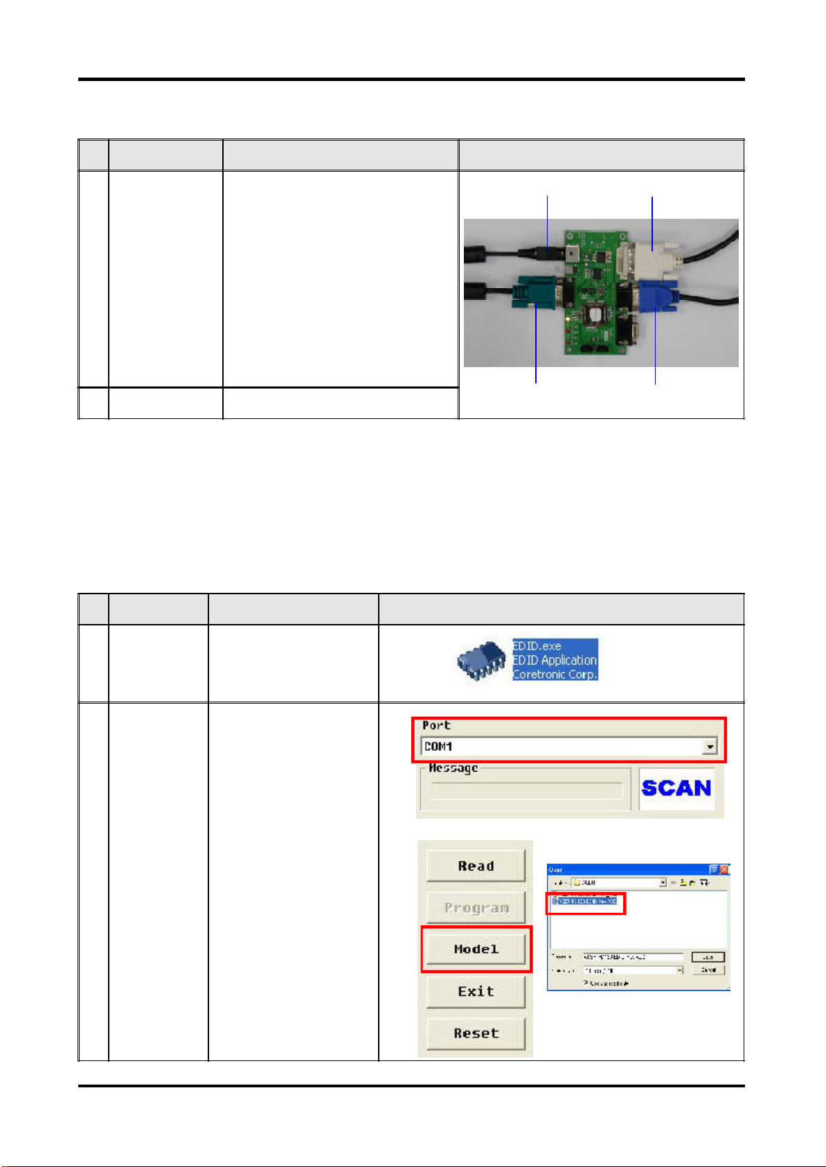
Hardware:
- V3 Fixture for EDI D Key-in
(Fixture: JP3 must be closed)
Item Photo Item Photo
RS-232 Cable
(F - M)
DVI Cable
(for "D" Model)
VGA Cable Power Cord
PC
Projector
(PD100 /
PD100D)
Power Adapter
for Fixture
Generic Fixture
One additional
monitor (for
checking the
program
execution)
Projector
(PD120 /
PD120D)
Projector
(XD1170D/
XD1270D)
15 Cha pter 2
Page 24
Setup Procedure
No Step Procedure Photo
1 Connect All Ports 1. Power Adapter to Fixture JP1
2. Fixture P1 to PC COM1 Port
3. Fixture P2 to Projector Analog Port
4. Fixture P3 to Projector Digital Port
2. Power On Fixture Power on Fixture
ED ID Key-In Procedure
Adapter
JP1
P1
RS-232 Cable
To Digital Port
P3
P2
To Analog Port
No Step Procedure Photo
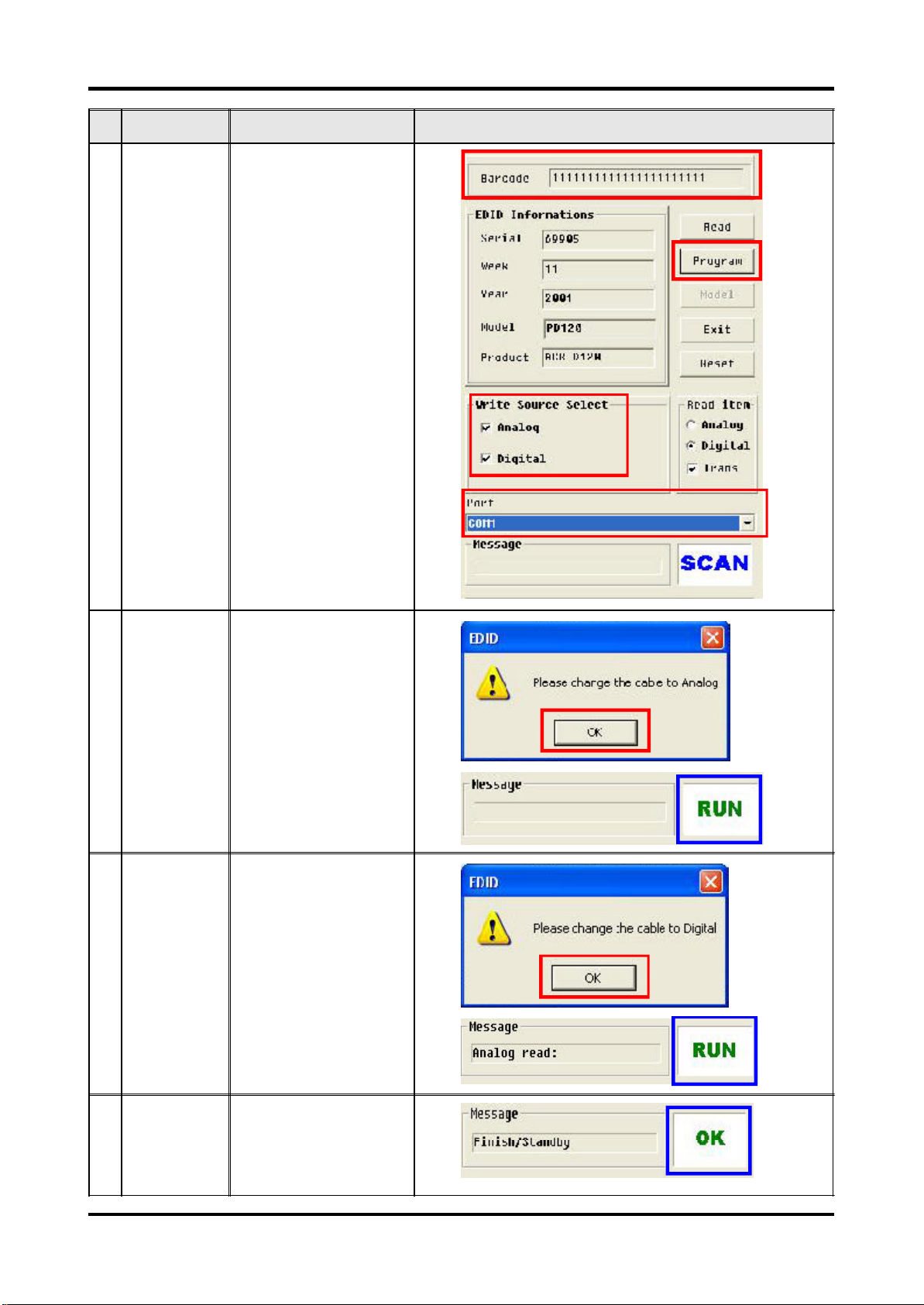
1 Execute EDID
Program.
2 Choose Model 1. In the Port Selection Bar,
Click on "EDID" to execute
EDID Program.
please choose the Port
that you use.
Ex: If you use "COM 1",
choose COM 1 in the
Port selection.
2. Click on "Model".
3. Choose the EDID that
responses to the model
that you choose.
1
32
Cha pter2 16
Page 25
No Step Procedure Photo
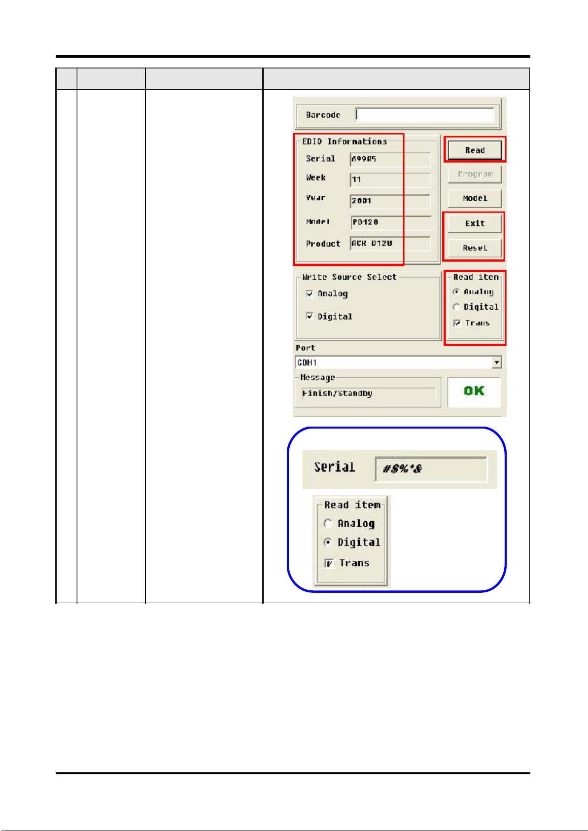
3 Key in Serial
Number
1. Key in the Serial Number
into the Barcode blank
space.
2. In "White Source Select",
make a check in "VGA"
and "DVI".
(Only for "D" Model.)
3. Check the COM Port is
"COM 1".
4. Click "Program".
1
4
2
3
4 Change Cable
to Analog
5 Change Cable
to Digital
"Please change the Cable
to Analog" message is
shown on the screen, then
click "OK".
Note: "RUN" message will
appear on the screen.
"Please change the Cable
to Digital" message is
shown on the screen, then
click "OK".
Note: "RUN" message will
appear on the screen.
6 Finished When the EDID program is
completed, the message,
"OK", will appear on the
screen.
17 Cha pter 2
Page 26
No Step Procedure Photo
7 Check the
whole process
1. In the "Read Item"
Selections, choose the
Port that you use.
Ex: If you use the Analog
Port, choose "Analog" in
the "Read Item".
Note: If the code in the
Serial Blank is scrambled,
please make a check in
"Trans".
2. Click on "Read" to read
EDID information.
3. The "EDID Informations"
will show the result.
4. Click "Reset" to do the
next unit or "Exit" to close
the EDID program.
3
2
4
1
Note
Cha pter2 18
Page 27
Chapter 3
Mechanical Disassembly & Reassembly
This section provides disassembly & Reassembly procedures for PD100 Micro Portable SVGA
DMD Projector. Before you begin any of these procedures, be sure to turn off the power,
computer system, and other attached devices; then disconnect the power cable from the
electrical outlet. Moreover, when you disassemble the projector, be sure to put the screws
in a safe place and separate them according to their category.
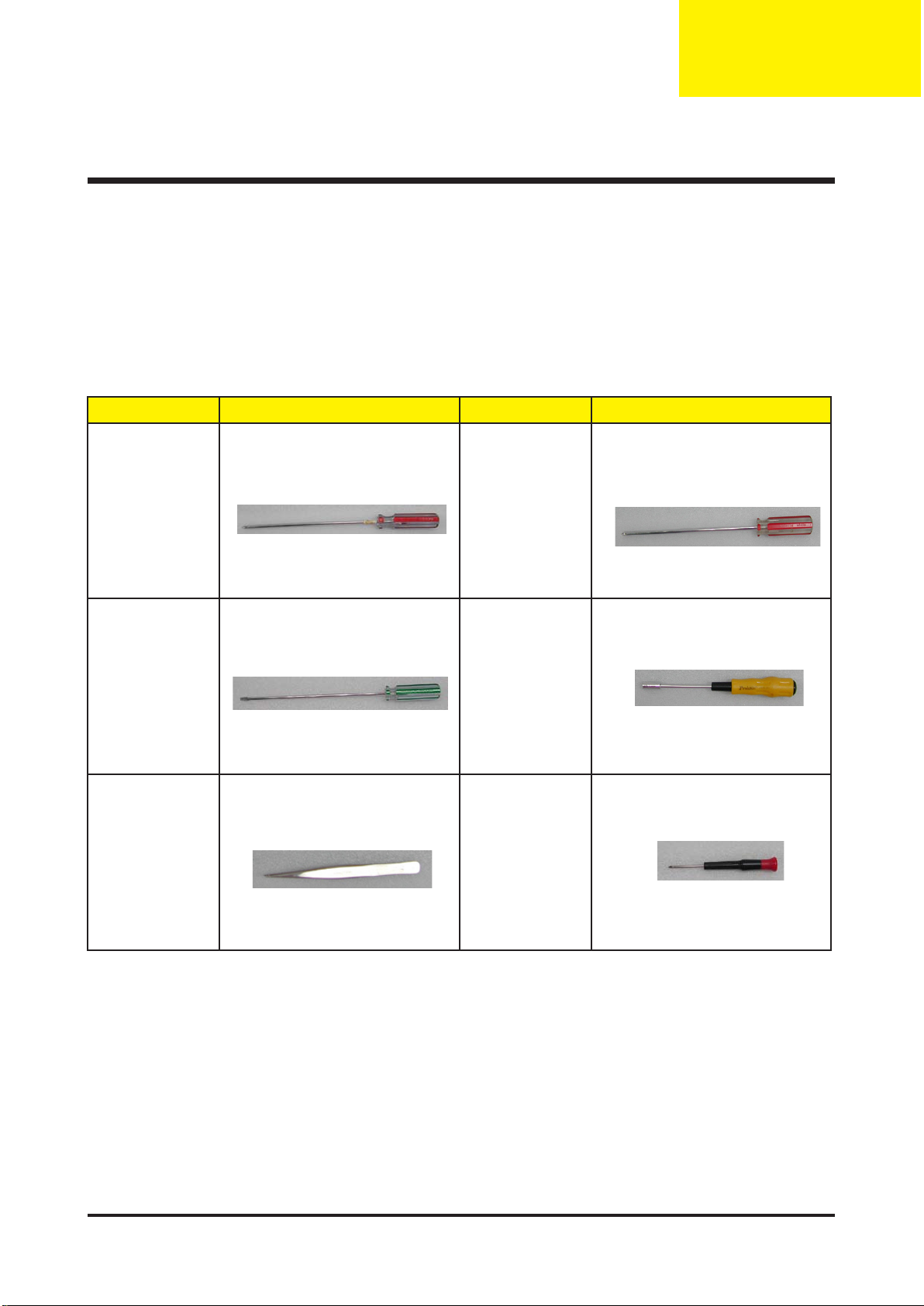
Equipment Needed
Item Photo Item Photo
Philips (+) : 107 Philips (+) : 102
Screw Bit
Tweezers Screw Bit
Hex Screw :
5mm
General Information
Before You Begin
Before proceeding with the disassembly procedure, make sure that you do the following
procedures:
1. Turn off the power of the system and all the peripherals.
2. Unplug the AC adapter and all power and signal cables from the system.
3. Anti-static wrist strap.
19 Chapter 3
Page 28

Chapter 3 20
Mechanical Disassembly Procedure
1. Remove Lamp Module
No Procedure Photo
1 Unscrew 2 screws to remove
the Lamp Cover.
2 Unscrew 2 screws to remove
the Lamp Module.
Page 29
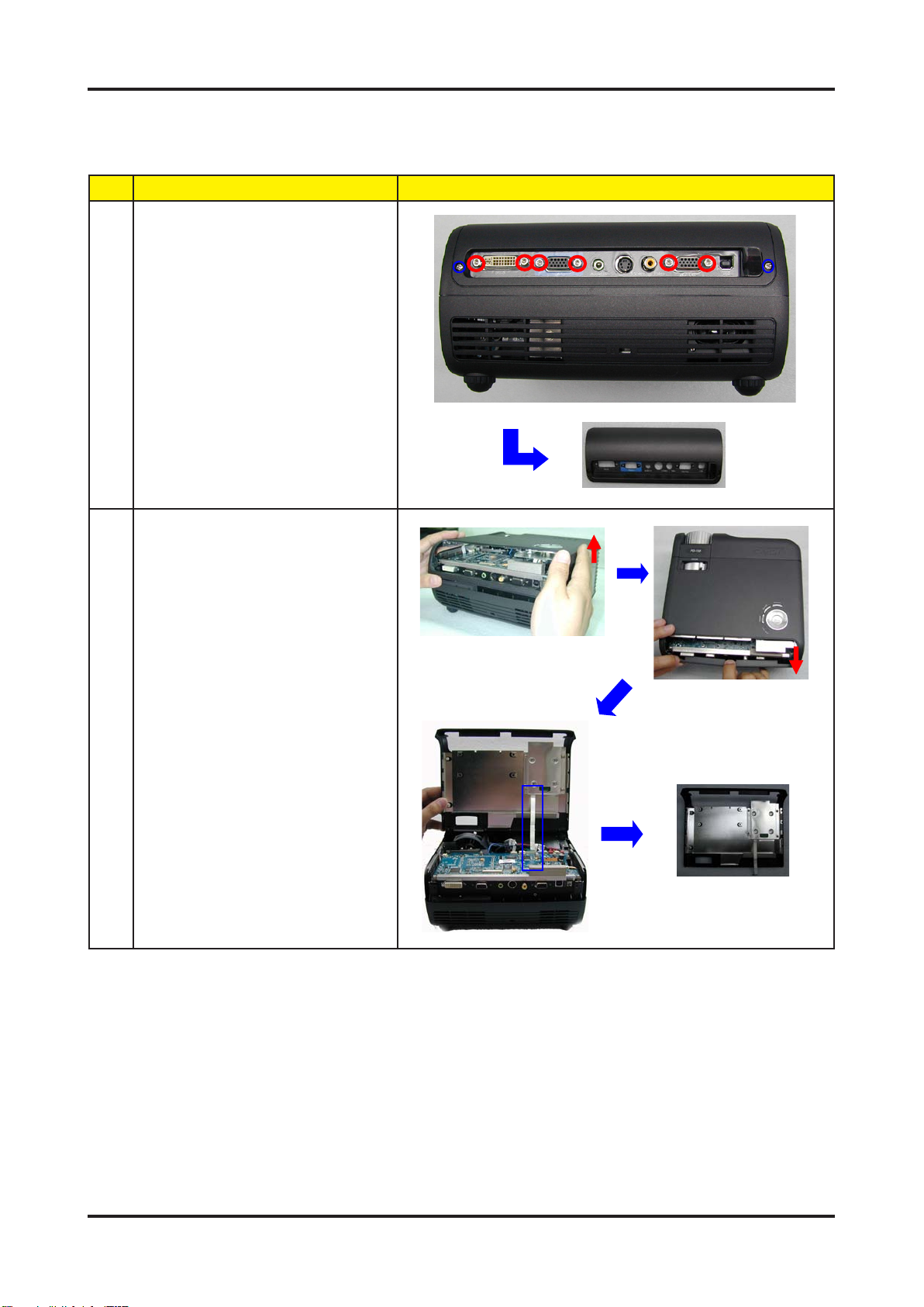
2. Remove IO Cover / Top Cover
No Procedure Photo
1 Unscrew 2 screws & 6 hex
screws to remove the IO
Cover.
2 1. Lift up the Top Cover rst
and then pull the Bottom
Cover for easily separting the
Top Cover.
2. Remove 1 FPC Cable to
remove the Top Cover.
21 Chapter 3
Page 30
Chapter 3 22
3. Remove Keypad Board
No Procedure Photo
1 1. Unscrew 4 screws to
remove the Keypad Board.
2. Separate the Keypad
Module.
2 Unscrew 2 screws to remove
the Top Cover Shielding.
Page 31

4. Remove Front Cover / IR Sensor Board / Elevator
Push Button
No Procedure Photo
1 1. Unscrew 1 screw to remove
the IR Receiver.
2. Unscrew 2 screws to
remove the Front Cover.
2 Unplug 1 connector (red color)
to remove the Front Cover
Module.
3 Remove the Front IR Cover
directly, and loosen 2 tenons
to remove the IR Receiver
Board.
4 Loosen 2 tenons to remove
the Elevator Push Button
directly.
23 Chapter 3
Page 32

Chapter 3 24
5. Remove Bottom Cover Module
No Procedure Photo
1 Remove Bottom Cover
Sponge.
2 Remove Side Covers. (Right
Cover & Left Cover)
Note 1:
When disassembing the Side
Cover, push the side cover
outside forwards and then pull
it up directly.
Note 2:
When reassembing the Side
Cover, please locate & align
the tenons as the picture
shows.
3 Unplug 2 tenons in the
shieldings to separate the
Bottom Cover Module with the
unit.
Page 33

6. Remove Main Board
No Procedure Photo
1 Unplug 8 connectors rst and
then unscrew 4 screws.
Note:
When Reassembling the
Main Board with the Top
Cover, please be aware of the
wire arrangement. The wire
arrangement should go as the
picture shows (not exceeding
1/2 of the red blank space) to
best allocate the Top Cover
Sponge.
2 1. Lift up the front part of Main
Board rst; then, take off the
Main Board.
2. Unplug 1 connector to
remove the Main Board.
25 Chapter 3
Page 34

Chapter 3 26
7. Remove EMI Shielding / Speaker
No Procedure Photo
1 Unscrew 4 screws to remove
the EMI Shielding Cover of
units.
2 Unscrew 2 screws to remove
the Speaker.
Note:
The Speaker isn’t designed
with error-proof. Please be
aware of wire-arrangement as
the picture shows.
Page 35

8. Remove Axial Fan Module
No Procedure Photo
1 Unscrew 3 screws to remove
Axial Fan Module.
2 Unscrew 4 screws to remove
the System Fan.
Note:
The System Fan isn’t
designed with error-proof.
Please be aware of the wirearrangement.
27 Chapter 3
Page 36

Chapter 3 28
9. Remove Lamp Driver
No Procedure Photo
1 Unscrew 4 screws.
2 Unplug 2 connectors to
remove the Lamp Driver
Module.
Note:
When assembling the LVPS,
please be aware of the
LVPS connector connection.
(the shorter wire should be
connected to the LVPS,
and the longer wire should
be connected to the Lamp
Driver.)
3 Unscrew 4 screws to separate
the Lamp Driver Housing.
Page 37

10. Remove LVPS / Interlock Swtich / Thermal Switch
No Procedure Photo
1 1. Unscrew 4 screws
2. Unscrew 1 screw in the
grounding wire.
3. Unplug 1 connector in the
Interlock Swtich to remove the
LVPS.
2 1. Unscrew 2 screws to
remove the Interlock Switch.
2. Unscrew 1 screw to remove
the Assy Thermal Switch
Board.
2
1
3
2
1
29 Chapter 3
Page 38

Chapter 3 30
11. Remove Engine Module
No Procedure Photo
1 Unscrew 3 screws to remove
the Engine Module.
2 1. Unscrew 1 screw to remove
the Light Cut.
2. Unscrew 1 screw to remove
the Thermal Sensor.
1
2
3 Unscrew 1 screw to remove
Photo Sensor Board.
4 1. Unscrew 4 screws and tear
off 1 EMI tape to remove the
Heatsink.
2. Unscrew 4 big hex screws
to remove the DMD Board.
3. Separate the DMD Board.
Page 39

No Procedure Photo
When reassembling the DMD
Module, please be aware of
the following Notes.
Note1:
The DMD Heasink Spring
Plate should be placed as the
picture shows.
Note 2:
The DMD Insulator Mylar &
DMD Heatsink Backer Plate
should be placed as the
picture shows.
Note 3:
The DMD Chip should be
reassembled as the picture
shows.
5 Unscrew 1 screw to remove
the Color Wheel.
6 1. Unscrew 2 screws to
remove the Zoom Ring &
Stopper.
2. Unscrew 3 screws to
remove the Focus Ring.
Zoom Ring
Zoom Ring Stopper
31 Chapter 3
Page 40

Chapter 3 32
12. Remove Elevator / Blower Fan
No Procedure Photo
1 Unscrew 4 screws to remove
the Elevator.
2 Unscrew 3 screws to remove
the Blower Fan.
Page 41

Mechanical Reassembly Procedure
1. Assemble Elevator / Blower Fan
No Procedure Photo
1 Screw 4 screws to assemble
the Elevator.
2 Screw 3 screws to assemble
the Blower Fan.
33 Chapter 3
Page 42

Chapter 3 34
2. Assemble Engine Module
No Procedure Photo
1 1. Screw 2 screws to
assemble the Zoom Ring &
Stopper.
2. Screw 3 screws to
assemble the Focus Ring.
2 Screw 1 screw to assemble
the Color Wheel.
Zoom Ring
Zoom Ring Stopper
3 When reassembling the DMD
Module, please be aware of
the following Notes.
Note1:
The DMD Heasink Spring
Plate should be placed as the
picture shows.
Note 2:
The DMD Insulator Mylar &
DMD Heatsink Backer Plate
should be placed as the
picture shows.
Note 3:
The DMD Chip should be
reassembled as the picture
shows.
Page 43

No Procedure Photo
1. Assemble the DMD Board
Components.
2. Screw 4 big hex screws to
assemble the DMD Board.
3. Screw 4 screws and put on
1 EMI tape to assemble the
Heatsink.
4 Screw 1 screw to assemble
the Photo Sensor Board.
5 1. Screw 1 screw to assemble
the Light Cut.
2. Screw 1 screw to assemble
the Thermal Sensor.
6 Assemble 3 screws to
assemble the Engine Module.
1
2
35 Chapter 3
Page 44

Chapter 3 36
3. Assemble Interlock Swtich / Thermal Switch / LVPS
No Procedure Photo
1 1. Screw 2 screws to
assemble the Interlock Switch.
2. Screw 1 screw to assemble
the Assy Thermal Switch
Board.
2
1
2 1. Screw 4 screws
2. Screw 1 screw in the
grounding wire.
3. Plug 1 connector in the
Interlock Swtich to assemble
the LVPS.
2
1
3
Page 45

4. Assemble Lamp Driver
No Procedure Photo
1 Screw 4 screws to assemble
the Lamp Driver Housing.
2 Plug in 2 connectors.
Note:
Please be aware of the wire
arrangement of the LVPS with
the Lamp Driver. (The shorter
wire should be connected to
the LVPS; while the longer
wire should be connected to
the Lamp Driver.)
3 Screw 4 screws to assemble
the Lamp Driver Module.
37 Chapter 3
Page 46

Chapter 3 38
5. Assemble Axial Fan Module
No Procedure Photo
1 Screw 4 screws to assemble
the System Fan.
2 Screw 3 screws to assemble
Axial Fan Module.
Note:
Please be aware of the wire
arrangement of the system
fan. (the wire should be in the
upper left side.)
Page 47

6. Assemble Speaker / EMI Shielding
No Procedure Photo
1 Screw 2 screws to assemble
the Speaker.
Note:
Please be aware of the wire
arrangement of the speaker.
2 Screw 4 screws to assemble
the EMI Shielding Cover of
Units.
39 Chapter 3
Page 48

Chapter 3 40
7. Assemble Main Board
No Procedure Photo
1 1. Plug 1 connector.
2. Locate the front part of
Main Board.
2 Screw 4 screws and plug in 8
connectors to assemble the
Main Board.
Note:
When Reassembling the
Main Board with the Top
Cover, please be aware of the
wire arrangement. The wire
arrangement should go as the
picture shows (not exceeding
1/2 of the red blank space) to
best allocate the Top Cover
Sponge.
Page 49

8. Assemble Bottom Cover Module
No Procedure Photo
1 Assemble the shieldings with
the Main Unit based on the 2
tenons.
2 Assemble Side Covers.
(Right Cover & Left Cover)
Note:
When reassembing the Side
Cover, please locate & align
the tenons as the picture
shows.
3 Assemble the Bottom Cover
Sponge.
41 Chapter 3
Page 50

Chapter 3 42
9. Assemble Front Cover / IR Sensor Board / Elevator
Push Button
No Procedure Photo
1 Assemble the Elevator Push
Button directly.
2 Assemble the IR Receiver
Board and put on the Front IR
Cover directly.
3 Plug in 1 connector (red color)
to assemble the Front Cover
Module.
4 1. Screw 1 screw to assemble
the IR Receiver.
2. Screw 2 screws to
assemble the Front Cover.
Page 51

10. Assemble Keypad Board
No Procedure Photo
1 Screw 2 screws to assemble
the Top Cover Shielding.
2 1. Assemble the Keypad
Module.
2. Screw 4 screws to
assemble the Keypad Board.
43 Chapter 3
Page 52

Chapter 3 44
11. Assemble Top Cover / IO Cover
No Procedure Photo
1 1. Put on 1 FPC Cable to
assemble the Top Cover.
2. Push the Bottom Cover
rst; then, push down the Top
Cover to assemble the Top
Cover.
2 Screw 2 screws & 6 hex
screws to assemble the IO
Cover.
Page 53

12. Assemble Lamp Module
No Procedure Photo
1 Screw 2 screws to assemble
the Lamp Module.
2 Screw 2 screws to assemble
the Lamp Cover.
45 Chapter 3
Page 54

Troubleshooting
Equipment Needed
- PC or Pattern Generator
- DVD Player (Video, S-Video, Audio)
- Quantum Data 802B or CHROMA 2327
LED Lighting Message
Power LED
Message
Red Blue
Chapter 4
Temp LED Lamp LED
Standby State
(Input power cord)
Lamp lighting O
Power on O * O O
Power off (Cooling) Quick Flashing
Error (Lamp fail)
Error (Thermal fail) O O
Error (Fan lock fail) O O Flashing O
Error (Over Temp.)
Error
(Lamp Breakdown)
Slow Flashing O O O
*
O O
O O O
O O O
*
O O
*
O O O *
=> Light On => Light Off
*
O
O
Cha pter 4 46
Page 55

Main Procedure
No Symptom Procedure
1 No Power - Ensure the Power Cord and AC Power Outlet are securely connected
- Check Lamp Cover and Interrupt Switch
- Ensure all connectors are securely connected and aren't broken
- Check DC-DC
- Check Ballast
- Check Main Board
2 Auto Shut Down - Check LED Status
a. Lamp LED Light
- Check Lamp
- Check Lamp Driver
- Check Main Board
b. Temp LED Light
- Check Thermal Sensor
- Check Thermal Switch
- Check Fan
c. Color Wheel
- Check Color Wheel
- Check Photo Sensor
d. No Power
- Refer to "No Power" troubleshooting
3 No Image - Ensure the Signal Cable and Source work as well
(If you connect multiple sources at the same time, use the "Source"
button on the control panel to swtich)
- Ensure all connectors are securely connected and aren't broken
- Check Main Board
- Check DMD Board
- Check Color Wheel
- Check DMD Chip
- Check Engine Module
4 No Light On - Ensure all connectors are securely connected and aren't broken
- Check Lamp Module
- Check DC-DC
- Check Ballast
- Check Main Board
5 Mechanical Noise - Check Color Wheel
- Check Fan Module
6 Line Bar / Line Defect - Sometimes it's because of the DMD Chip and the DMD Board did
not assemble properly
- Check DMD Board
- Check DMD Chip
- Check Main Board
7 Image Flicker - Do "Reset" of the OSD Menu
- Ensure the Signal Cable and Source work as well
- Check Lamp Module
- Check Color Wheel
- Check DMD Board
- Check Main Board
8 Color Abnormal - Do "Reset" of the OSD Menu
- Adjust Color Wheel Index
- Check Main Board
- Check DMD Board
- Check Color Wheel
47 Cha pter 4
Page 56

No Symptom Procedure
9 Poor Uniformity / Shadow - Ensure the Projection Screen without dirt
- Ensure the Projection Lens is clean
- Ensure the Brightness is within spec.
(Replace the Lamp if the Brightness is less than spec.)
- Check Engine Module
10 Dead Pixel / Dust
(Out of spec.)
11 Garbage Image - Ensure the Signal Cable and Source work as well
12 Remote Controll or Control
Panel Failed
13 Function Abnormal - Do "Reset" of the OSD Menu
- Ensure the Projection Screen without dirt
- Ensure the Projection Lens is clean
- Clean DMD Chip and Engine Module
- Check DMD Chip
- Check Engine Module
- Check Main Board
- Check DMD Board
- Remote Control
a. Check Battery
b. Check Remote Control
c. IR Receiver
- Control Panel
a. Check FPC
b. Check Keypad
c. Check Main Board
- Check Main Board
- Check DMD Board
Cha pter 4 48
Page 57

Function Test & Alignment Procedure
Product
- PD100 / PD100D/ PD120D / PD120 / XD1170D / XD1270D
Te st Equipment
- I BM PC with XGA resolution (Color Video Signal & Pattern Generator)
- DVD player with Multi-system (NTSC/PAL/SECAM), equipped “Component” “S-Video” and
“Composite”
- HDTV Tuner or Source (480P, 1080i)
- Minolta CL-100
- Quantum Data 802B or CHROMA2316
- After changing parts, check the information below.
Charge
Parts/Update
M/B v v v v v v
FW v v v v v
Color Wheel v
Lamp Module v
Version
Update
Color Wheel
Index
ADC
Calibration
Video
Calibration
Reset Lamp
Use Time
Factory
Reset
Te st Condition
- Circumstance Brightness : Dark room less than 2.5 lux.
- I nspection Distance : 1.5m~3m for functional inspection
- Screen Size : 60 inches diagonal (wide)
- After repairing each PD100, the unit should be burn-in (Refer to the table below).
Symptom Burn-in Time
Normal Repair 2 Hours
NFF 4 Hours
EDID
Auto Shutdown 6 Hours
49 Cha pter 4
Page 58

Inspection Procedure
No Step Specification Procedure
1 Frequency
and Tracking
2 Boundary Horz. And Vert.
3 Focus The text in the
4 HDTV No discolor - Test Signal : 480P, 1080i (PD100)
5 Color
Performance
Eliminate visual
wavy noise by
Rsync,
Frequency or
Tracking
selection.
position of video
should be
adjustable to be
the screen
frame.
corner should be
clear after adjust
the focus ring.
1. No image
(discolor)
2. No light
leakage
- Test Signal : 800x600@75Hz (PD100)
- Test Pattern : General 1
- check and see if image sharpness and
focus are well-performed.
- No video noise is allowed.
- Test Signal : 800x600@75Hz (PD100)
- Test Pattern : General 1
- Adjust Resync or Frequency / Tracking /
H. Position / V. Position to the inner of the
screen.
- Test Signal : 800x600@75Hz (PD100)
- Test Pattern : Full Screen
- Adjust the center clearly; meanwhile, one
slightly vague corner in the image is allowed.
- Test Pattern : Master
- Equipment: Quantum Data 802B or
CHROMA2327
*Please refer to page 4~7 to enter Service Mode.
Use 480P signal, smtpe bar pattern to do video
calibration; then, 4:3 screen and 1080i signal. If the
test result was in discoloration or flickering, please
return the unit back to the repair center. (by Model)
- Test Signal : 800x600@75Hz (PD100)
- Test Pattern : 64 RGBW Scale Pattern & 32 Grays
Pattern
- Please check and ensure if each color is
normal and distinguishable.
- If not, please adjust color index of the
Engineering Mode.
6 Screen
Uniformity
Should be
compliant with
60%.(Minimum)
- Test Signal : 800x600@75Hz (PD100)
- Test Pattern : Full White Pattern & Full Black
Pattern
- Please check and ensure the unit is under the
spec.
- Please check and see if it's in normal conidtion.
- If not, please return the unit to repair area.
*Please check and see if there are dead
pixels on DMD Chip.
- The total number and distance of dead pixels
should be compliant with the spec.
Note:
(1) Bright Pixel:
Test Pattern: Full Black Pattern
- Please check and ensure that the unit cannot
accept any bright pixel.
- If not, please return the unit to repair area.
(2) Dark Pixel:
Test Pattern: Full White Pattern
- Please check and ensure that the pixel number
should be smaller or amount to 5 pixels.
- If not, please return the unit to repair area.
Cha pter 4 50
Page 59

No Step Specification Procedure
7 Light Leak The unit can't
8 Calibration Calibration
9 Contrast /
Brightness
accept the
leakage is
brighter than
Gray 10 pattern
Pattern should
be in full screen
mode
Gray level should
be
distinguishable
and without color
abnormal
- Test Signal : 800x600@75Hz (PD100)
- Test Pattern : 32 Grays, Gray 10_HP, Gray 30_HP
(From Top to Bottom)
- Please check and see if the light leaks.
- Follow up TI DMD Chip Spec.
- Once Main Board is changed, firmware upgrade,
Video Calibration & ADC Calibration should be
done as well.
- Video Calibration
- Test Signal : 720x480@75Hz (PD100)
- Test Pattern : Master
- PC Calibration
- Test Signal : 800x600@75Hz (PD100)
- Test Pattern : White (Top) Black (Bottom)
Note:
1. Calibration Pattern should be in Full Screen
Mode.
2. Please refer to 4-6. Guide to Entering Service
Mode and Facotry Reset for entering Service
Mode.
3. Choose and access Video Calibration & PC
Calibration for correction in Service Mode.
Choose "Exit" to leave the Service Mode after all.
- Test Pattern: 64 RGBW scale
10 R, G, B and
White Color
Performance
Each R, G, B
color should be
normal without
color abnormal
issue
- Test Pattern: R, G, B and White Color
51 Cha pter 4
Page 60

No Step Specification Procedure Photo
11 Dead Pixel
(Bright pixel)
Dead Pixel
(Dark pixel)
12 Blemish
(Bright)
Cannot accept
any bright pixel
The numbers of
dead pixel
should be
smaller or
amount to 6
pixel.
The bright
blemish cannot
be accepted if
the problem
appear with Gary
30 pattern
- Test Pattern : Full Black
- Test Pattern : Full White
- Test Pattern : Full Black / Gray 30
13 Blemish
(Dark)
The dark blemish
cannot be
accepted if the
problem appear
with Blue 60
pattern.
- Test Pattern : Full white / Blue 60
Cha pter 4 52
Page 61

Guide to Entering Servic e Mode and Factory Res et (PD100)
No Item Steps
1 Service Mode Please do the following steps to enter Service Mode:
1. Turn on the projector.
2. Press "Power", "Left" button, "Left" button and "Menu" by order to enter the
Service Mode. (As the following pictures show)
1
Power
2 Factory Reset After final QC step, we have to erase all saved change again and restore the
factory defaults. Execute the Factory Reset to restore the deault setting.
2
“Left” button
3
“Left” button
4
Menu
53 Cha pter 4
Page 62

Expl oded Overview
PD100 Exploded Overview
Chapter 5
Exploded Parts List
Item Part Number Description
1 70.82V22G001 ASSY FRONT COVER MODULE PD100
2 70.82V24G001 ASSY TOP COVER MODULE PD100
3 70.82V15G001 ASSY BOTTOM HOUSING MODULE PD100
4 70.82G09G001 ASSY LAMP MODULE EP7190
5 70.82V23G001 ASSY BACK COVER DC MODULE PD100
6 70.82V33G001 ASSY LAMP COVER MODULE PD100
7 85.1A323.100 SCREW PAN MECH M3*10 BLACK
8 85.005AGG040 SCREW I/O STEEL #4-40UNC*H4*L5.5 NYLOK
9 85.5A323.060 SCREW BIN MECH M3*6 Black
10 61.00079G001 GROUNDING CABLE CLAMP FN-008 "PINGOOD
11 61.00018G002 LOCK SCREW PAN MECH M3*8.5-3.5 BLACK
Note: Please refer to RSPL for updated Part Number.
Cha pter 5 54
Page 63

PD120 Exploded Overview
Exploded Parts List
Item Part Number Description
1 70.82V03G001 ASSY FRONT COVER MODULE PD120
2 70.82V07G001 ASSY TOP COVER MODULE PD120
3 70.82V01G001 ASSY BOTTOM HOUSING MODULE PD120
4 70.82G09G001 ASSY LAMP MODULE EP7190
5 70.82V14G001 ASSY BACK COVER DC MODULE PD120
6 70.82V32G001 ASSY LAMP COVER MODULE PD120
7 85.1A323.100 SCREW PAN MECH M3*10 BLACK
8 85.005AGG040 SCREW I/O STEEL #4-40UNC*H4*L5.5 NYLOK
9 85.5A323.060 SCREW BIN MECH M3*6 Black
10 61.00079G001 GROUNDING CABLE CLAMP FN-008 "PINGOOD
11 61.00018G002 LOCK SCREW PAN MECH M3*8.5-3.5 BLACK
Note: Please refer to RSPL for updated Part Number.
55 Cha pter 5
Page 64

PD100 Assy Bottom Housing Module
Exploded Parts List
Item Part Number Description
1 70.82V09G001 ASSY BOTTOM BASE MODULE PD120
2 70.82V17G001 ASSY ENGINE MODULE PD100
3 61.82G12G001 LAMP LIGHTCUT TOP FOR E19 AL 0.6t EP7190
4 70.82V10G001 ASSY AXIAL FAN MODULE PD120
5 70.82V04G001 ASSY BOTTOM EMI SHIELDING MODULE PD120
6 80.82V51G001 PCBA MAIN BD PD100
7 51.82V19G001 ZOOM RING MYLAR PD120
8 70.82V25G001 ASSY BOTTOM COVER MODULE PD100
9 52.82V04G001 BOTTOM COVER SPONGE PD120
10 51.82G16G001 ELEVATOR FOOT PC+ABS C6200 EP7190 "GREEN'
11 42.87120G001 W.A. GROUND #20 UL1007 BLACK 80mm p3.0/p3.0 LT20
12 85.1A123.050 SCREW PAN MECH M3*5 Ni
13 85.1A626G050 SCREW PAN MECH M2.6*5 BLACK NYLOK
14 70.82G19G001 ASSY LAMP DRIVER MDULE EP7190
15 41.82G03G001 EMI GASKET USB CONNECTOR EP719
Note: Please refer to RSPL for updated Part Number.
Cha pter 5 56
Page 65

PD120 Assy Bottom Housing Module
Exploded Parts List
Item Part Number Description
1 70.82V09G001 ASSY BOTTOM BASE MODULE PD120
2 70.82V11G001 ASSY ENGINE MODULE PD120
3 61.82G12G001 LAMP LIGHTCUT TOP FOR E19 AL 0.6t EP7190
4 70.82V10G001 ASSY AXIAL FAN MODULE PD120
5 70.82V04G001 ASSY BOTTOM EMI SHIELDING MODULE PD120
6 80.82V01G001 PCBA MAIN BD PD120
7 51.82V19G001 ZOOM RING MYLAR PD120
8 70.82V02G001 ASSY BOTTOM COVER MODULE PD120
9 52.82V04G001 BOTTOM COVER SPONGE PD120
10 51.82G16G001 ELEVATOR FOOT PC+ABS C6200 EP7190 "GREEN'
11 42.87120G001 W.A. GROUND #20 UL1007 BLACK 80mm p3.0/p3.0 LT20
12 85.1A123.050 SCREW PAN MECH M3*5 Ni
13 85.1A626G050 SCREW PAN MECH M2.6*5 BLACK NYLOK
14 70.82G19G001 ASSY LAMP DRIVER MDULE EP7190
15 41.82G03G001 EMI GASKET USB CONNECTOR EP719
Note: Please refer to RSPL for updated Part Number.
57 Cha pter 5
Page 66

PD100 Assy Bottom Cover Module
Exploded Parts List
Item Part Number Description
1 51.82V02G002 BOTTOM COVER PC+ABS PD100
2 51.82V17G001 LEFT COVER PC+ABS PD120
3 51.82V18G001 RIGHT COVER PC+ABS PD120
4 52.89601.001 ADJUST FOOT RUBBER EP759
5 86.03123.035 HEX CAP HEAD NUT M3*0.5P L3.5 NI
6 52.82V10G001 BOTTOM COVER SPONGE-2 PD120
Note: Please refer to RSPL for updated Part Number.
Cha pter 5 58
Page 67

PD120 Assy Bottom Cover Module
Exploded Parts List
Item Part Number Description
1 51.82V02G001 BOTTOM COVER PC+ABS PD120
2 51.82V17G001 LEFT COVER PC+ABS PD120
3 51.82V18G001 RIGHT COVER PC+ABS PD120
4 52.89601.001 ADJUST FOOT RUBBER EP759
5 86.03123.035 HEX CAP HEAD NUT M3*0.5P L3.5 NI
6 52.82V10G001 BOTTOM COVER SPONGE-2 PD120
Note: Please refer to RSPL for updated Part Number.
59 Cha pter 5
Page 68

PD120 Assy Bot tom Base Module
Exploded Parts List
Item Part Number Description
1 49.88604.002 SPEAKER 8ohm 2W X16 EP759
2 85.1A123.050 SCREW PAN MECH M3*5 Ni
3 52.82G11G001 SPEAKER SPONGE EP7190
4 61.82V01G001 EMI SHIELDING AL PD120
Note: Please refer to RSPL for updated Part Number.
Cha pter 5 60
Page 69

PD100 Assy Top Cover M odule
Exploded Parts List
Item Part Number Description
1 51.82V03G001 TOP COVER PC+ABS PD120
2 61.82V04G001 TOP COVER SHIELDING SPTE PD120
3 51.82Q03G001 KEYPAD MAIN BUTTON PC+ABS PD322
4 51.82Q05G001 LED HOUSING PC PD322
5 51.82Q06G001 POWER LED HOUSING PC PD322
6 80.82Q03G001 PCBA KEYPAD BOARD PD322 ''GREEN''
7 61.82V03G001 KEYPAD SHIELDING AL PD120
8 85.WA123.040 SCREW PAN TAP M3*4 Ni
9 42.82V02G001 CABLE FFC 14P P=0.5 120mm PD120
10 51.82Q04G011 KEYPAD MENU BUTTON PC+ABS PD120
11 41.82V05G001 EMI GASKET W4*H3*L15mm PD120
12 41.82V04G001 EMI GASKET W10*H6.5*L70mm PD120
13 41.81M02G001 EMI GASKET W17*H23*L30mm
Note: Please refer to RSPL for updated Part Number.
61 Cha pter 5
Page 70

PD120 Assy Top Cover M odule
Exploded Parts List
Item Part Number Description
1 51.82V03G001 TOP COVER PC+ABS PD120
2 61.82V04G001 TOP COVER SHIELDING SPTE PD120
3 51.82Q03G001-B KEYPAD MAIN BUTTON PC+ABS PD322
4 51.82Q05G001 LED HOUSING PC PD322
5 51.82Q06G001-B POWER LED HOUSING PC PD322
6 80.82Q03G001 PCBA KEYPAD BOARD PD322 ''GREEN''
7 61.82V03G001 KEYPAD SHIELDING AL PD120
8 85.WA123.040 SCREW PAN TAP M3*4 Ni
9 42.82V02G001 CABLE FFC 14P P=0.5 120mm PD120
10 51.82Q04G011 KEYPAD MENU BUTTON PC+ABS PD120
11 41.82V05G001 EMI GASKET W4*H3*L15mm PD120
12 41.82V04G001 EMI GASKET W10*H6.5*L70mm PD120
13 41.81M02G001 EMI GASKET W17*H23*L30mm
Note: Please refer to RSPL for updated Part Number.
Cha pter 5 62
Page 71

PD120 Assy Bot tom Base Module
Exploded Parts List
Item Part Number Description
1 61.82G01G001 BASE PLATE Mg ALLOY AZ91D EP7190
2 51.85816.001 LIMIT SWITCH HOLDER PPS XB31
3 51.85824.001 LIMIT SWITCH BOTTOM HOLDER PPS XB31
4 75.88514.002 ASSY LIMIT SWITCH CHERRY DB3C A1LB-5A
5 85.1A62G.050 SCREW PAN MECH M2.6*5 BLACK NYLOK
6 70.82V34G001 ASSY ELEVATOR MODULE PD120
7 61.00029.001 SCREW PAN MECH M3*5*D8 Ni
8 61.87340G001 STAND OFF M3*4L D8.0 2100MP
9 85.3A122.040 SCREW CAP MECH M2*4 Ni
10 41.82V01G001 EMI GASKET W17*H27*L35mm PD120
11 76.82G01G001 BUY ASSY W.A. 2P 150mm LVPS/LAMP EP719
12 61.85913.001 ELEVATOR SPRING SUS304 SB21
13 80.82V04G001 PCBA THERMAL SENSOR BOARD PD120
14 51.82G24G001 BASE PLATE INSULATION MYLAR FOR LVPS EP7190
15 70.82V26G001 ASSY BLOWER FAN MODULE PD120
16 85.1C224G050 SCREW PAN MECH M4*5 COLOR W/TOOTH WASHER
17 85.1A123.050 SCREW PAN MECH M3*5 Ni
18 70.82V31G001 ASSY LVPS MODULE PD120
19 52.88504G001 LVPS BOTTOM THERMAL PAD 26*21*3mm Fujipoly GR-b
Note: Please refer to RSPL for updated Part Number.
63 Cha pter 5
Page 72

PD120 Assy Axial Fan Module
Exploded Parts List
Item Part Number Description
1 49.80N01G001
2 61.82V02G001 FAN-LAMP BRACKET AL PD120
3 85.1F123.260 SCREW PAN MECH E/SF M3*26 Ni
4 52.82V07G001 LAMP BRACKET SPONGE PD120
5 51.00075.001 WIRE MOUNTS PG-FW-4D XB31
Note: Please refer to RSPL for updated Part Number.
SUNON 70*20 R-TYPE AXIAL FAN, GM1207PKVX-A 70*70*20mm, JST
CONNECTOR,GREEN SUMITUDE
Cha pter 5 64
Page 73

PD100 Assy Engine M odule
Exploded Parts List
Item Part Number Description
1 70.82V27G001 ASSY ENGINE BOTTOM COVER MODULE PD120
2 70.82V18G001 ASSY ENGINE TOP MODULE PD100
3 85.1A123.050 SCREW PAN MECH M3*5 Ni
4 41.82V02G001 EMI TAPE W30*L30mm PD120
Note: Please refer to RSPL for updated Part Number.
65 Cha pter 5
Page 74

PD120 Assy Engine M odule
Exploded Parts List
Item Part Number Description
1 70.82V27G001 ASSY ENGINE BOTTOM COVER MODULE PD120
2 70.82V12G001 ASSY ENGINE TOP MODULE PD120
3 85.1A123.050 SCREW PAN MECH M3*5 Ni
4 41.82V02G001 EMI TAPE W30*L30mm PD120
Note: Please refer to RSPL for updated Part Number.
Cha pter 5 66
Page 75

PD100 Assy Engine Top Cover Module
Exploded Parts List
Item Part Number Description
1 11.009F0G005-C CNNT F 166P FOR 0.55" SVGA LGA DMD SOCKET;FOXCONN
2 23.82G01G002 PROJECTION LENS BARREL CHA
3 48.859DMGD13
4 51.80B31G002 DMD INSULATOR MYLAR 0.435t T90
5 51.82V09G001 FOCUS RING PC+ABS PD120
6 51.82V10G001 ZOOM RING PC+ABS PD120
7 51.82G08G001 ZOOM RING ORBIT PC+ABS C6200 EP7190
8 51.82G22G001 ZOOM ANTI-ABRASION TEFLON EP7190
9 52.82G03G002 RELAY SEALED RUBBER-2 EP719
10 52.82G10G001 RELAY CUSHION RUBBER EP7190
11 52.87130G001 RUBBER BLOWER 595925
12 52.87319G001 DMD THERMAL PAD 18*13*0.5t
13 52.89627G002 DMD SEAL RUBBER BF1000 3.2t EP719
14 61.80J48G002 DMD HEATSINK BACKER PLATE A6061 739
15 61.82G02G001 ENGINE TOP COVER Mg ALLOY AZ91D EP7190
16 61.83A03G001 DMD HEATSINK AL 1070 DP718
17 61.88608G001 DMD HEATSINK SPRING PLATE SUS301 0.4t Ivy10X
18 61.88611G001 DMD SCREW Ivy10X
19 61.89643G001 DMD MASK PLATE SUS301 0.15t EP759
20 00.82V02G001 BARE PCB L:6 DMD BD FOR PD120
21 85.1A123.050 SCREW PAN MECH M3*5 Ni
22 85.1A123.060 SCREW PAN MECH M3*6 Ni
23 85.YA321G051 SCREW FLAT HEAD TAP M1.7x5 D3 BALCK
Note: Please refer to RSPL for updated Part Number.
67 Cha pter 5
Page 76

PD120 Assy Engine Top Cover Module
Exploded Parts List
Item Part Number Description
1 11.009F0G005 CNNT F 166P FOR 0.55" SVGA LGA DMD SOCKET;FOXCONN
2 23.82G01G002 PROJECTION LENS BARREL CHA
3 48.82GDMGD01 DMD 1024*768 PIXEL DDR FTP 0.55" XGA
4 51.80B31G002 DMD INSULATOR MYLAR 0.435t T90
5 51.82V09G001 FOCUS RING PC+ABS PD120
6 51.82V10G001 ZOOM RING PC+ABS PD120
7 51.82G08G001 ZOOM RING ORBIT PC+ABS C6200 EP7190
8 51.82G22G001 ZOOM ANTI-ABRASION TEFLON EP7190
9 52.82G03G002 RELAY SEALED RUBBER-2 EP719
10 52.82G10G001 RELAY CUSHION RUBBER EP7190
11 52.87130G001 RUBBER BLOWER 595925
12 52.87319G001 DMD THERMAL PAD 18*13*0.5t
13 52.89627G002 DMD SEAL RUBBER BF1000 3.2t EP719
14 61.80J48G002 DMD HEATSINK BACKER PLATE A6061 739
15 61.82G02G001 ENGINE TOP COVER Mg ALLOY AZ91D EP7190
16 61.83A03G001 DMD HEATSINK AL 1070 DP718
17 61.88608G001 DMD HEATSINK SPRING PLATE SUS301 0.4t Ivy10X
18 61.88611G001 DMD SCREW Ivy10X
19 61.89643G001 DMD MASK PLATE SUS301 0.15t EP759
20 00.82V02G001-B BARE PCB L:6 DMD BD FOR PD120
21 85.1A123.050 SCREW PAN MECH M3*5 Ni
22 85.1A123.060 SCREW PAN MECH M3*6 Ni
23 85.YA321G051 SCREW FLAT HEAD TAP M1.7x5 D3 BALCK
Note: Please refer to RSPL for updated Part Number.
Cha pter 5 68
Page 77

PD120 Assy Back Cover DC Module
Exploded Parts List
Item Part Number Description
1 51.82V12G001 BACK IR LENS PC PD120
2 51.82V21G001 BACK IO OVERLAY-DC PC PD120
3 41.82V12G001 EMI TAPE W41*L129mm PD120
4 51.82V04G011 BACK COVER-DC PC+ABS PD120
Note: Please refer to RSPL for updated Part Number.
69 Cha pter 5
Page 78

PD100 Assy Back Cover DC Module
Exploded Parts List
Item Part Number Description
1 51.82V12G001 BACK IR LENS PC PD120
2 51.82V21G001 BACK IO OVERLAY-DC PC PD120
3 41.82V12G001 EMI TAPE W41*L129mm PD120
4 51.82V04G012 BACK COVER-DC PC+ABS PD100
Note: Please refer to RSPL for updated Part Number.
Cha pter 5 70
Page 79

PD100 Assy Front Cover
Exploded Parts List
Item Part Number Description
1 51.82V01G002 FRONT COVER NORYL 9406P PD100
2 51.82V08G002 FRONT PUSH BUTTON PC+ABS PD100
3 51.82V11G001 FRONT IR LENS PC PD120
4 52.82V02G001 FRONT IR COVER RUBBER PD120
5 80.82V05G001 PCBA IR SENSOR BD FOR PD120
6 35.82V01G002 MODEL NAME LABEL PC PD100
7 35.82V03G001 ACER LOGO LABEL PD120
8 52.82V11G001 FRONT COVER SPONGE PD120
9 51.82V22G001 MYLAR LIGHT CUT PD120
Note: Please refer to RSPL for updated Part Number.
71 Cha pter 5
Page 80

PD120 Assy Blower Fan Module
Exploded Parts List
Item Part Number Description
1 49.83A01G001 DELTA 4520 BLOW
2 52.82G08G001 BLOWER 4520 RUBBER EP7190
Note: Please refer to RSPL for updated Part Number.
Cha pter 5 72
Page 81

PD120 Assy Engine Bottom Cover Module
73 Cha pter 5
Page 82

Exploded Parts List
Item Part Number Description
1 23.82G02G001 MIRROR WITH ONE COATING SURFACE
2 23.82G06G001 ASPHERICAL ZEONEX RELAY LENS
3 23.82G10G001 SQUARE UV-IR 17*17mm^2 T=2.75mm
4 23.82G20G001 BK7 CONDENSER LENS p13.00mm
5 23.82G20G011 BK7 CONDENSER LENS p15.00mm
6 43.80N01G001 THERMAL SWITCH 120J TI , YS11A120B-026, WHITE JST CONNECTOR,
7 51.82G13G001 CONDENSER HOLDER PC+20%GF EP7190 "GREEN'
8 52.82G04G002 RELAY SIDE SEALED RUBBER-2 EP719
9 52.82G09G001 CONDENSER CUSHION RUBBER EP7190
10 52.82G12G001 FAN HOLDER SEALED-1 HT800 EP719
11 52.82G13G001 FAN HOLDER SEALED-2 HT800 EP719
12 52.82G14G001 FAN HOLDER SEALED-3 HT800 EP719
13 61.82G03G001 ENGINE BOTTOM COVER Mg ALLOY AZ91D EP7190
14 61.82G11G001 MIRROR HOLDER PLATE SUS301 0.25t EP7190
15 51.82G25G001 RELAY LENS MYLAR EP719
16 61.82G19G001 ROD HIDE RAY PLATE AL 0.4t EP7190
17 61.82G21G001 ROD FIX PLATE SUS301 0.25t EP7190
18 61.82G22G001 UV-IR GLASS HOLDER SUS301 0.2t EP7190
19 70.82G15G001 ASSY COLOR WHEEL MODULE EP7190
20 70.83S05G001 ASSY ROD MODULE PJ406D
21 75.82G08G001 BUY ASSY 50*25 BLOWER FAN DUCT AL EP719
22 85.0A122G030 SCREW DOUBLE FLAT MECH M2*3Ni
23 85.1A123.050 SCREW PAN MECH M3*5 Ni
24 85.1A523G080 SCREW PAN MECH M3*8 Ni NYLOK
Note: Please refer to RSPL for updated Part Number.
Cha pter 5 74
Page 83

PD120 Assy Le ns Cap Module
Exploded Parts List
Item Part Number Description
1 52.82V01G001 LENS COVER RUBBER PD120
2 61.82V08G001 LENS COVER PLATE PD120
3 51.83150G001 CAP STRAP TDP-T90
Note: Please refer to RSPL for updated Part Number.
75 Cha pter 5
Page 84

PD120 Assy LVPS Module
Exploded Parts List
Item Part Number Description
1 42.80S07G001 W.A. 14P 190mm LVPS TO M/B TDP-T90 ''
2 42.81G01.001 W.A. 2P #20 160mm LAPS/BALLAST H31
3 75.80W19G001 ASSY LVPS LITEON 200W 2300MP
Note: Please refer to RSPL for updated Part Number.
Cha pter 5 76
Page 85

PD100 Assy Lamp Cover Module
Exploded Parts List
Item Part Number Description
1 51.82V13G002 LAMP COVER NORYL 9406P PD100
2 61.82V09G001 LAMP COVER PLATE SPTE PD120
3 52.82V08G001 LAMP COVER SPONGE PD120
Note: Please refer to RSPL for updated Part Number.
77 Cha pter 5
Page 86

PD120 Assy Lamp Cover Module
Exploded Parts List
Item Part Number Description
1 51.82V13G001 LAMP COVER NORYL 9406P PD120
2 61.82V09G001 LAMP COVER PLATE SPTE PD120
3 52.82V08G001 LAMP COVER SPONGE PD120
Note: Please refer to RSPL for updated Part Number.
Cha pter 5 78
Page 87

PD120 Assy El evator Module
Exploded Parts List
Item Part Number Description
1 51.82V06G001 ELEVATOR HOLDER PC+ABS PD120
2 51.82V07G001 ELEVATOR PUSH PC+ABS PD120
3 51.86809.001 ELEVATOR BODY NYLON+GF DP725
4 61.86814.001 ELEVATOR EXTEND SPRING DP725
5 61.85913.001 ELEVATOR SPRING SUS304 SB21
Note: Please refer to RSPL for updated Part Number.
79 Cha pter 5
Page 88

Appendix A
Ex ploded Overv iew
D.C. XD1170D
Cha pter 5
80
Page 89

Item P/N Description
1 70.82V47G001 ASSY FRONT COVER MODULE XD1170D
2 70.82V63G001 ASSY TOP COVER MODULE-1 XD1270D
3 70.82V46G001 ASSY BOTTOM HOUSING MODULE XD1170D
4 70.82V61G001 ASSY LAMP MODULE XD1270D
5 70.82V48G001 ASSY BACK COVER MODULE XD1270D
6 75.82V09G011 BUY ASSY LAMP COVER MODULE XD1270D
7 85.1A323G100 SCREW PAN MECH M3*10 BLACK
8 85.005AGG040 SCREW I/O STEEL #4-4UNC*H4*L5
9 85.5A323G060 SCREW BIN MECH M3*6 BLACK
10 61.00079G001 GROUNDING CABLE CLAMP FN-008"GREEN"
11 61.00018G002 LOCK SCREW PAN MECH M3*8.5-3.5
12 51.00001G001 CABLE TIE PG-YJ-80
Cha pter 5
81
Page 90

ASSY FRONT COVER MODULE XD1170D
Item P/N Description
1 51.82V01G011 FRONT COVER NORYL 9406P XD1270D
2 51.82V08G011 FRONT PUSH BUTTON PC+ABS XD1270D
3 51.82V11G001 FRONT IR LENS PC PD120
4 52.82V02G001 FRONT IR COVER RUBBER PD120
5 80.82V05G001 PCBA IR SENSOR BD FOR PD120
6 35.82V01G032 MODEL NAME LABEL PC XD1170D
7 52.82V11G001 FRONT COVER SPONGE PD120
8 51.82V22G001 MYLAR LIGHT CUT PD120
9 41.82V18G001 EMI FRONT COVER TAPE PD120
10 52.82V09G001 LENS SUPPORT RUBBER PD120
Cha pter 5
82
Page 91

ASSY ENGINE MODULE XD1170D
Item P/N Description
1 70.82V52G001 ASSY ENGINE BOTTOM COVER MODULE XD1270D
2 70.82V54G001 ASSY ENGINE TOP COVER MODULE XD1170D
3 85.1A123G050 SCREW PAN MECH M3*5 Ni
4 41.82K09G001 EMI TAPE 30*50mm
Cha pter 5
83
Page 92

ASSY BOTTOM HOUSING MODULE XD1170D
Cha pter 5
84
Page 93

PART NUMBER LIST
Item P/N Description
1 70.82V42G001 ASSY BOTTOM BASE MODULE XD1270D
2 70.82V53G001 ASSY ENGINE MODULE XD1170D
3 61.82G12G001 LAMP LIGHTCUT TOP FOR E19 AL
4 70.82V10G001 ASSY AXIAL FAN MODULE PD120
5 70.82V59G001 ASSY BOTTOM EMI SHIELDING MODULE XD1270D
6 80.82V71G002 PCBA MAIN BOARD FOR XD1170D
7 51.82V19G011 ZOOM RING MYLAR XD1270D
8 70.82V60G001 ASSY BOTTOM COVER MODULE XD1270D
9 52.82V04G002 BOTTOM COVER SPONGE-2 PD120
10 51.82G16G001 ELEVATOR FOOT PC+ABS EP719
11 42.87120G001
W.A. GROUND #20 UL1007 BLACK 80mm%%c3.0/%%c3.0
LT20
12 85.1A123.050 SCREW PAN MECH M3*5
13 85.1A626G050 SCREW PAN MECH M2.6*5 BLACK NYLOK
14 70.82V44G001 ASSY LAMP DRIVER MODULE XD1270D
15 43.80N01G001
THERMAL SWITCH 120C TI, YS11A120B-026, WHITE JST
CONNECTOR.
16 51.82V09G011 FOCUS RING PC+ABS XD1270D
17 85.YA321G052 SCREW FLAT HEAD TAP M1.7*5 D2.5 BLACK
18 51.82V10G011 ZOOM RING PC+ABS XD1270D
19 51.82G08G002 ZOOM RING ORBIT PC MN3600H EP719
Cha pter 5
85
Page 94

ASSY ENGINE TOP COVER MODULE XD1170D
Cha pter 5
86
Page 95

PART NUMBER LIST
Item P/N Description
1 11.009F0G005
2 23.85R01G001 PROJECTION LENS YM09H
3 48.859DMGD13 DMD 800*600 PIXEL DDR FTP 0.55" SVGA
4 51.80B31G002 DMD INSULATOR MYLAR 0.435t T90
5 51.82G22G001 ZOOM ANTI-ABRASION TEFLON EP7190 "GREEN"
6 52.82G03G002 RELAY SEALED RUBBER-2 EP719
7 52.82G10G001 RELAY CUSHION RUBBER EP7190 "GREEN"
8 52.87130G001 RUBBER BLOWER 595925 "GREEN"
9 52.87319G001 DMD THERMAL PAD 18*13*0.5t "GREEN"
10 52.89627G002 DMD SEAL RUBBER BF1000 3.2t EP719
11 61.80J48G002 DMD HEATSINK BACKER PLATE 739 AL6061 "GREEN"
12 61.82G02G001 ENGINE TOP COVER Mg Alloy-AZ91D EP7190
13 61.83A03G001 DMD HEATSINK AL 1070 DP718
14 61.88608G001 DMD HEATSINK SPRING PLATE SUS301 0.4t Ivy10X
CNNT F 166P FOR 0.55" SVGA LGA DMD
SOCKET;FOXCONN
15 61.88611G001 DMD SCREW Ivy10X "GREEN"
16 61.89643G001 DMD MASK PLATE SUS301 0.15t EP759
17 80.82V02G001 PCBA DMD BD FOR PD120
18 85.1A123G050 SCREW PAN MECH M3*5 NI
19 85.1A123G060 SCREW PAN MECH M3*6 Ni
Cha pter 5
87
Page 96

XD1170D PROJECTION DISPLAY PROJECTOR
ASSY SYSTEM FAN 80x25 MODULE
Cha pter 5
88
Page 97

PART NUMBER LIST
Item P/N Description
1 DC.82V70G001 D.C. XD1170D
2 36.86B01G001 USER'S GUIDE MULTILINGUAL (CD) ACER PD127
3 42.87305G001 CABLE VGA 15P 1.8M BLK 2100MP
4 42.86502G002 ADAPTER D-SUB TRANSFORM RCA JACK PD120
5 45.82V01G101 INFRARED REMOTE CONTROLLER PD100 ACER
6 36.86B02G001 QUICK START CARD MULTILINGUAL ACER PD127
7 36.00006G031 WARRANTY CARD ,EUROPE FOR ACER
8 42.87205G001 CABLE COMPOSITE VIDEO 1.8M 3200MP
9 46.82U01G002 BATTERY #4 1.5V LR03 TDP-P8 (ACER)
10 42.87217G001 CABLE S-VHS 2M 3200MP
11 42.87215G001 CABLE MINI JACK TO MINI JACK 2M 3200MP
12 42.87304G001 CABLE USB(A) TO USB(B) 1.8M BLK 2100MP ; MOLEX
13 51.86213G001 PE BAG ZIPPER #9 W/RECYCLING MARK EzPro 736
14 53.82V02G001 SOFT CARRY BAG-2 PD120
15 70.82V29G001 ASSY LENS CAP MODULE PD120
16 35.86301G001 SPEC LABEL BLANK PD120
17 35.82V05G001 WARNING LABEL 30mm*40mm XD1270D
18 35.52302G091 LABEL CARTON 108*92 BLANK
19 51.80T48G001 PE BAG 450*350*0.07 (Recycle Mark)
20 57.00001G001 PACK SIO2 DRIER 20g
21 55.82V01G001 PAPER SUPPORT PD120
22 56.82V01G001 CUSHION-R EPE EP120
23 56.82V02G001 CUSHION-L EPE EP120
24 55.80N01G006 CARTON CARRY BOX PD120
25 55.80T01G011 CARTON ONTSIDR BOX PD523
26 35.82V02G001 LABEL CARTON(SEAL) 110*50mm PD120
27 42.50112G003
CABLE POWER CORD 1830mm SP-023+1S14 EUR
"ACER"
28 42.53506G002 CABLE POWER-CORD AC SP60+AS14 1.8M BLACK
29 42.83620G002 CABLE POWER CODE AC 6ft BLACK(SWITZERLAND)
Cha pter 5
88
Page 98

Appendix A
Ex ploded Overv iew
D.C. XD1270D
Chapter 5
89
Page 99

Item P/N Description
1 70.82V45G001 ASSY FRONT COVER MODULE XD1270D
2 70.82V63G001 ASSY TOP COVER MODULE-1 XD1270D
3 70.82V41G001 ASSY BOTTOM HOUSING MODULE XD1270D
4 70.82V61G001 ASSY LAMP MODULE XD1270D
5 70.82V48G001 ASSY BACK COVER MODULE XD1270D
6 75.82V09G011 BUY ASSY LAMP COVER MODULE XD1270D
7 85.1A323G100 SCREW PAN MECH M3*10 BLACK
8 85.005AGG040 SCREW I/O STEEL #4-4UNC*H4*L5
9 85.5A323G060 SCREW BIN MECH M3*6 BLACK
10 61.00079G001 GROUNDING CABLE CLAMP FN-008"GREEN"
11 61.00018G002 LOCK SCREW PAN MECH M3*8.5-3.5
12 51.00001G001 CABLE TIE PG-YJ-80
Chapter 5
90
Page 100

ASSY LVPS MODULE XD1270D
Item P/N Description
1 42.82V04G001 W.A. 14P/16P 190mm LVPS TO M/B XD1270D
2 42.81G01G001 W.A. 2P #20 160mm LAPS/BALLAST PD120
3 75.80W18G002 ASSY LVPS MATRITEK 200W EP719(CT2300-B)
Chapter 5
91
 Loading...