

Page 1

Acer PD-115
Service Guide
Service guide files a nd update s are available
on the CSD web; for more information,
plea se refer to http://csd.acer.com.tw
100% Recycled Pa per
Page 2

Copyright
Copyright © 2003 by Acer Incorporated. All rights reserved. No part of this publication
may be reproduced, tra nsmitted, tra n scribed, stored in a retrieval system, or tra n slated
into any la nguage or computer la nguage, in a ny f orm or by a ny mea n s, electronic,
mecha nical, magnetic, optical, chemical, ma nual or otherwise, without the prior written
permission of Acer Incorporated.
Disclaimer
The information in this guide is subject to change without notice.
Acer Incorporated makes no representation s or warra nties, e ither expressed or
implied, with respect to the contents here of a nd spe cifically disclai ms a ny warranties
of merchanta bility or fitness f or a ny particular purpose. Any Acer Incorporated software
described in this manual is sold or licensed “as is”. Should the progra ms prove defe c
tive following their purchase, the buyer (and not Acer Incorporated, its distributor, or its
dealer) a ssumes the entire cost of all ne cessary servicing, re pair , a nd any incidental or
consequential damages resulting from any defe ct in the software.
Acer is a registered trademark of Acer Corporation.
Intel is a registered trademark of Intel Corporation.
Pentium and Pentium II/III are trade marks of Intel Corporation.
Other brand a nd product n ames are trademarks a nd/or registered tra demark s of their respec tive holders.
Page 3

Conventions
The following conventions are used in this manual
segassemneercS.neercsnoraeppatahtsegassemlautcasetoneD
etoN
gninraW
noituaC
tnatropmI
.cipottnerrucehtotdetaler
.snoitcacificepsgniodtonrogniod
.smelborperawtfosroerawdrah
.serudecorpfotnemhsilpmocca
noitamrofnilanoitiddafoseceipdnastibseviG
morftluserthgimtahtegamadynaotuoystrelA
elbissopdiovaotserusaemyranoituacerpseviG
ehtottnavelersnoitcacificepsodotuoysdnimeR
Page 4

Preface
Before using this information and the product it supports, please rea d the f ollowing
general information.
1. This Service Guide provides you with all te chnical inf ormation relating to the BASIC
CONFIGURA TION decided for Acer’s “global” product of fering. To better fit local
market requirements a nd enha nce product competitiveness, your regional of fice MAY
have decided to extend the functionality of a ma chine (e.g. a dd-on card, modem, or
extra memory ca pa bility). These LOCALIZED FEATURES will NOT be covered
in this generic service guide. In such ca ses, ple ase contact your regional off ices or the
responsible personnel/cha nnel to provide you with further technical details.
2. Please note WHEN OR DERING FRU PARTS, that you should check the most up to-date information available on your region al web or channel. If, f or whatever reason,
a part number cha nge is ma de, it will not be noted in the printed Service Guide. For
ACER-AUTHORIZED SERVICE PROVIDERS, your Acer off ice may have a DIFFER
ENT part number code to those given in the FRU list of this printed Service Guide.
You MUST use the list provided by your regional Acer of fice to order FRU parts f or
repair and service of customer machines.
Page 5

Table of Contents
Chapter 1 System Introduction 1
T echnical Spe cification .......................................................................................................1
La mp Specification............................................................................................................. 2
System Block Diagra m .......................................................................................................6
Optics Conceptual Drawing................................................................................................7
Cha pter 2 Firmware Update 8
Setup T ool / Equi pment.......................................................................................................8
Upgrading Procedure .........................................................................................................8
Chapter 3 M achine Dissassembly and Repla ce ment 10
General Information ...........................................................................................................11
Disassemble Lamp Module...............................................................................................12
Disassemble IO Cover & Top Cover..................................................................................13
Disassemble Speaker & Front Cover ...............................................................................14
Disassemble Front Fan...................................... ...............................................................15
Disassemble Front IR Board & IR Cover...........................................................................16
Disassemble Video IO .......................................................................................................17
Dissassemble Main Board..... ...........................................................................................18
Disassemble Ballast Module & Back IR.............................................................................19
Disassemble Optical Engine..............................................................................................20
Disassemble Back Cover.................................................................................................. 21
Disassemble Back IR Cover , AC Outlet........................................................................... 22
Disassemble Power Module............................................................................................. 23
Disassemble Mylar & Ground Plate.................................................................................. 24
Disassemble Heatsink & DMD Board.............................................................................. 25
Disassemble DMD Assembly & DMD.............................................................................. 26
Disassemble Thermal Board............................................................................................ 27
Disassemble Optical Engine Fan...................................................................................... 28
Exploded Overview............................................................................................................29
Page 6

Table of Contents
Cha pter 4 T rouble shooting 30
Video Signal troubleshooting.............................................................................................31
Operation FunctionTroubleshooting............................................................................... ...34
Power SourceTroubleshooting..........................................................................................35
Function T e st and Align ment.................................................................................... ...........36
Equipment Needed...................................................................................................36
T est Condition......................................................................................... ...................36
T e st Display Modes a nd Patterns .....................................................................................37
Compatible Modes ..................................................................................................37
Function Test Display Pattern..................................................................................38
Cha pter 5 Connector Inf ormation 40
Introduction...........................................................................................................................40
Main Board......................................................................................................................... 40
Power Board .....................................................................................................................46
Ballast Board ......................................................................................................................48
Chapter 6 FRU(FieldReplaceable Unit) List 49
FRU List...............................................................................................................................50
Page 7
System Introduction
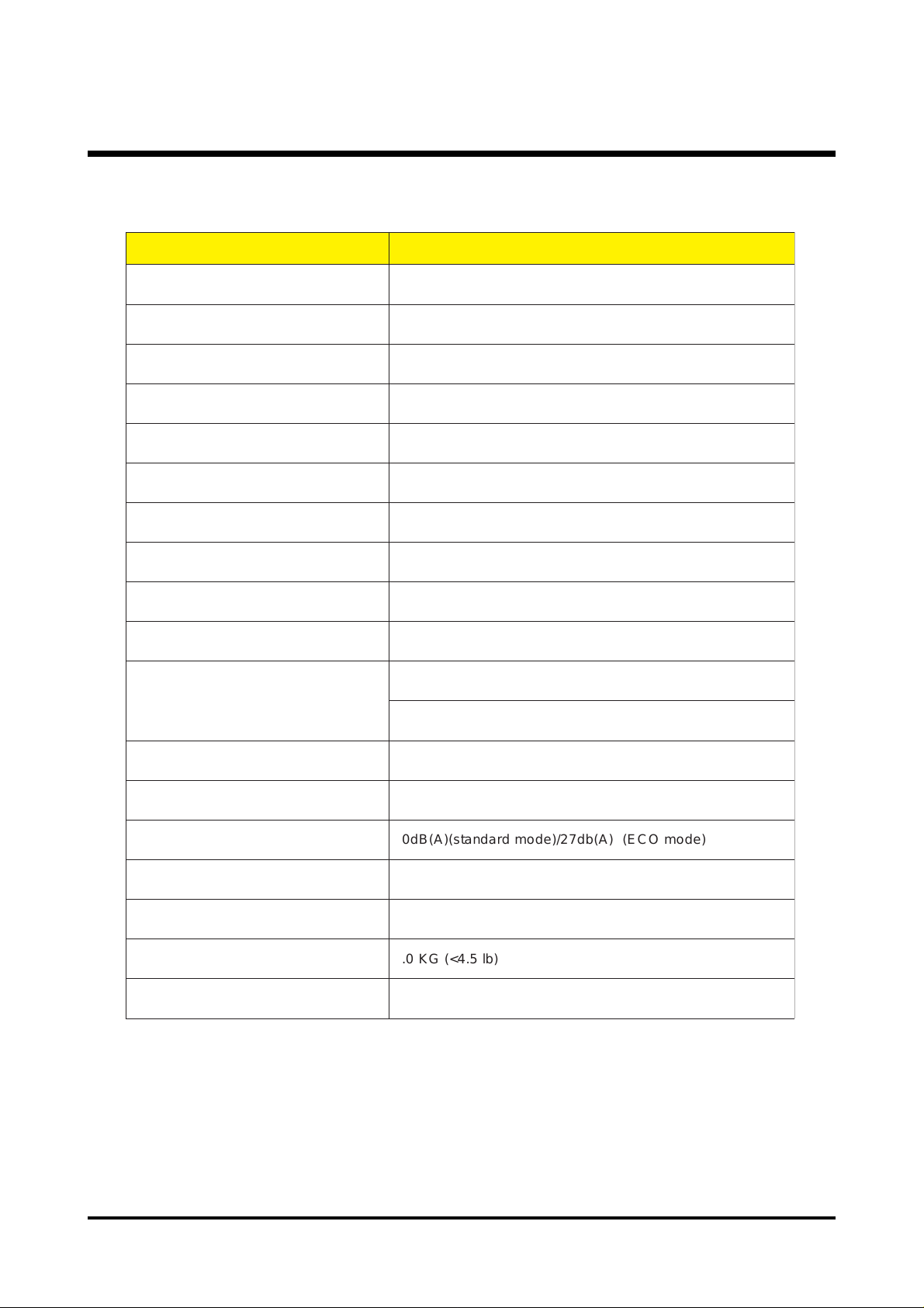
31dB(A)(standard mode) / 29dB(A) ECO mode)
2.3 KG (<5.1 lb)
T e chnical Spe cification
metI noitpircseD
epyTyalpsiDrotcejorPPLDpihCelgniS
epyTpmaLW002
ssenthgirBnemuL0071
oitaRtsartnoC)niM()ffo/nolluF(1:0002
)slexiP(noituloseR006x008
ytimrofinU%09
noitasnepmoClacitpOlennuTthgiL
Chapter 1
htgneLlacoFmm2.42~2.02
eziSneercSsehcni033~5.72
ecnatsiDworhTreteM21~2.1
ytilibitapmoC
ytidimuHnoitarepO%08
erutarepmeTnoitarepOC53+~5+
esioNdnuoS )edomOCE()A(bd72/)edomdradnats()A(Bd03
tnemeriuqeRrewoPzH06~05,v042~001
)DxHxW(snoisnemiDmm29x891x652
thgieW)bl5.4<(GK0.2
noitacifitreC LUc,LU,II-ICCV,BssalCCCF,BssalCEC
)"zHK97~13(ycneuqerflatnoziroH"
)"zH58~05(ycneuqerflacitreV"
1 Chapter 1
Page 8

La mp Specif ication
1.Lamp Scope
The product is a lamp system consisting of a short arc burner within a reflector, and an
electric la mp ballast.
Lamp type NSH200PT
Driver type PHG201G16**
2. Lamp Specification : NSH200PT
2.1 Dimension s
Lamp see 2.6 figure (Lamp & Ballaster drawing)
Overall length 66.6
Arc length 1.1mm(typical)
Reflector type Elliptical
Lamp weight man. 75g
2.2 Marking on the lamp
Position of marking On ceramic and reflector
Lot number NSH200PT
Type no. Serial number(ex. HD0100 , HDA001 , HDB001...)
2.3 Operating and mea s urement conditions
Ballast type Test conditions stable at 200W with
NSH200PT
Rated lamp wattage 200W
Lamp position
Horizontal (within 15 degree to horizontal optical axis)
Chapter 1 2
Page 9

2.4 Initial Ignition performance
Wattage
DC 200
Lamp Voltage (V)
82 V
Lamp Current (A)
2.4
Efficiency (lm/w)
66
2.5 Optical characteristics
Based on meansurement on standard optical unit by USHIO Lighting
Brightness typ. 1600 lumen
Color coordinates x : 0.3 +/- 0.02
y : 0.32 +/- 0.02
Flickering and arc jump less than 5 %
The flicker and arc jump over than 5% should be less than 10 time s during 10 minutes
operation
3 Chapter 1
Page 10
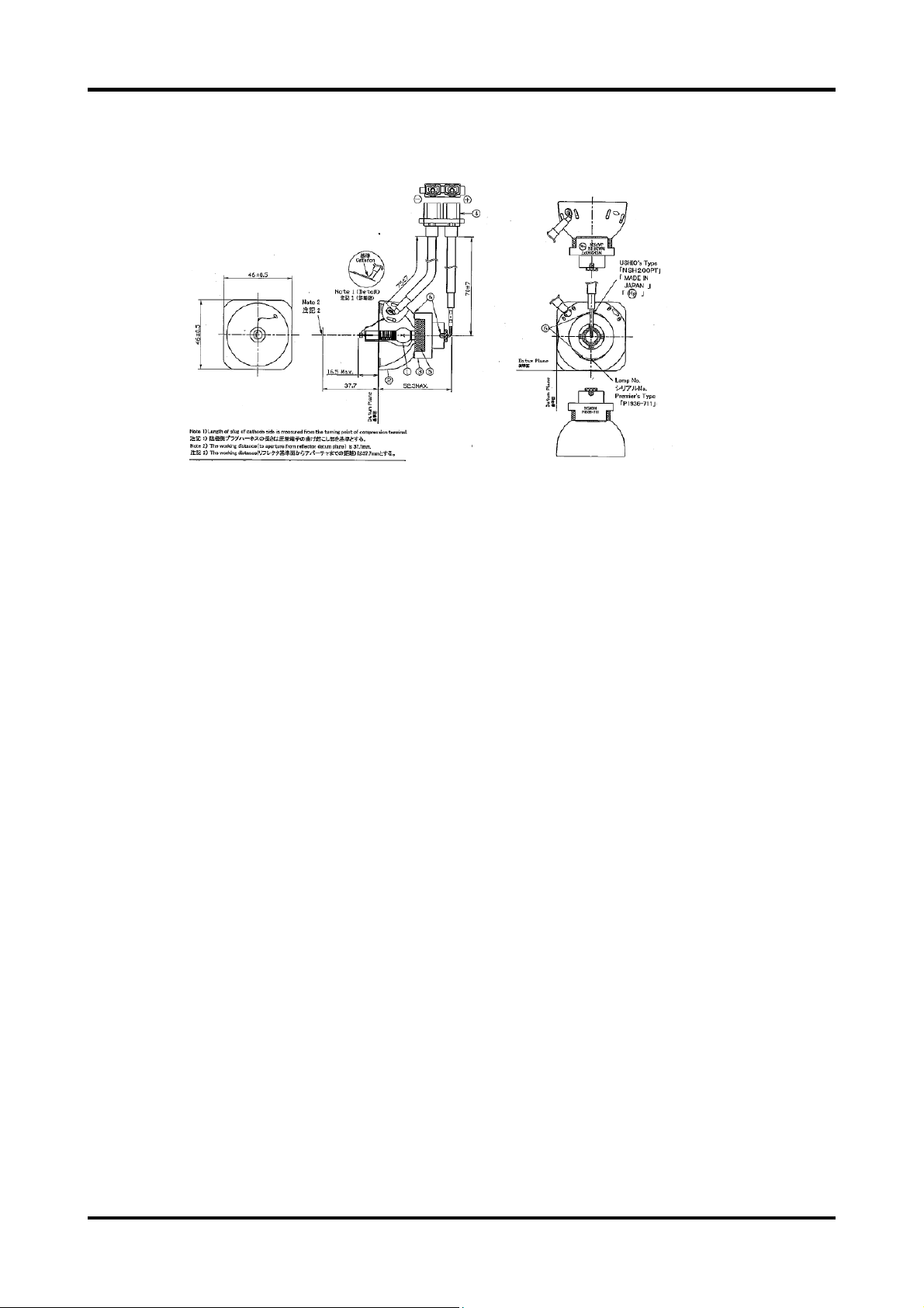
2.6 Lamp & Ballaster drawing
2.7 Instructions for use
1. The la mp be comes high temperature after turning of f the projector with the power
button. If you touch the la mp, you may scald your finger . When you repla ce the la mp,
wait for at least 45 minutes for the lamp to cool down.
2. Do not touch the lamp glass at a ny ti me. The lamp may explode due to improper
handling, including the touching of the lamp gla ss.
3. La mp lifeti me may differ from lamp to la mp a nd a ccording to the environment of use.
There is no guara ntee of the same lifetime for each lamp. Some lamps may fail or
terminate their lifetime in a shorter period of ti me than other similar lamps.
4. A lamp may explode as a result of vibration, shock or degradation a s a result of hours
of use a s its lifeti me draws to a n end. Risk of explosion may dif fer a ccording to the
environment or conditions in which the projector a nd lamp are being used.
5. Wear protective gloves and eyeglasses when fixing or deta ching the la mp.
6. Fa ster on-off-cycle s will damage the lamp and reduce lamp life. W ait at le ast for 5
minutes to turn off the projector after powering on.
7. Do not operate the lamp in proximity to pa per , cloth, or other combustible materi al nor
cover it with such materials. Otherwise it could cause a fire.
Chapter 1 4
Page 11

8. Do not operate the lamp in an atmosphere containing a n inflammable substance, such
a s thinner . Otherwise it could cause a f ire or explosion.
9. Thoroughly ventilate the area or the room when operating the la mp in a n oxygen
atmosphere (in the air). If ozone is inhaled, it could cause heada ches, n ausea,
dizziness, etc.
10. The inorganic mercury is involved in the lamp. If the lamp bursts, the mercury in side the
la mp will go out of the projector. Leave the area immediately if the lamp shatters while
being operated and ventilate the area f or at least 30 minutes in order to avoid the
inhalation of mercury fumes. Otherwise it could be harmful to user’s health.
1 1. Dispose of the used lamp according to local regulations.
12. Ensure that screws are tightened properly. Screws not tightened fully may result in
injury or a ccidents.
13. Since the la mp is made of glass, do not drop the unit and do not scratch the gla ss.
14. Do not reuse the old lamp. This could cause the la mp to explode.
15. Be sure to turn off the projector and un plug the AC power cord before re pla cing the
lamp.
16. Do not use the proje ctor with the la mp cover re moved.
Disposal : For disposal of spent lamps, always consult federal, state, local and
provincial hazardous wa ste disposal rule s a nd regulation s to ensure
proper disposal.
Caution : This la mp e mits ultra violet (UV) radi ation and operates at high
pressure.
This la mp may only be used in enclosed f ixtures that comply with
UL1572.
Due to the high luminous ef fica cy, the UV radi ation which the lamp
emits a nd the high pressure within the lamp, P-VIPâ lamps may only be
operated within enclosed, purpose-built housings.
5 Chapter 1
Page 12
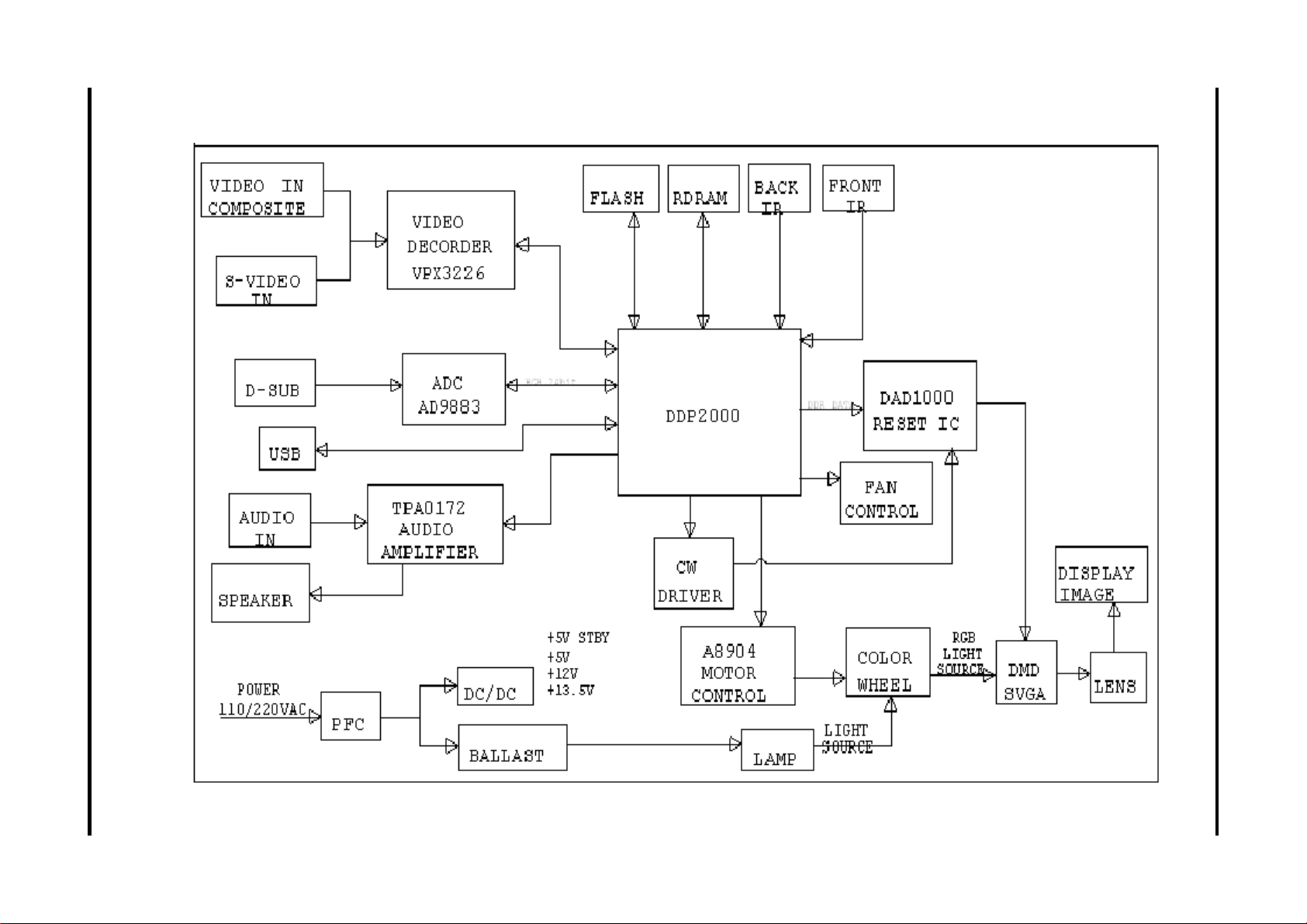
System Block Di agra m
Chapter 1 6
Page 13
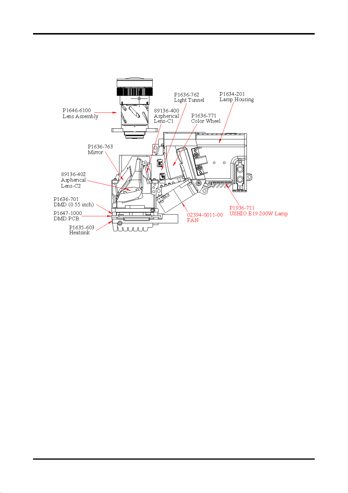
Optics-Conceptual Drawing
7 Chapter 1
Page 14
Firmware Upgrade
This cha pter provide s the equi pment needed, setup a nd upgra ding procedure for
Firmware upgrade.
Setup Tool / Equipment
1. Computer
2. USB Cable (see right picture)
3. Power Coard
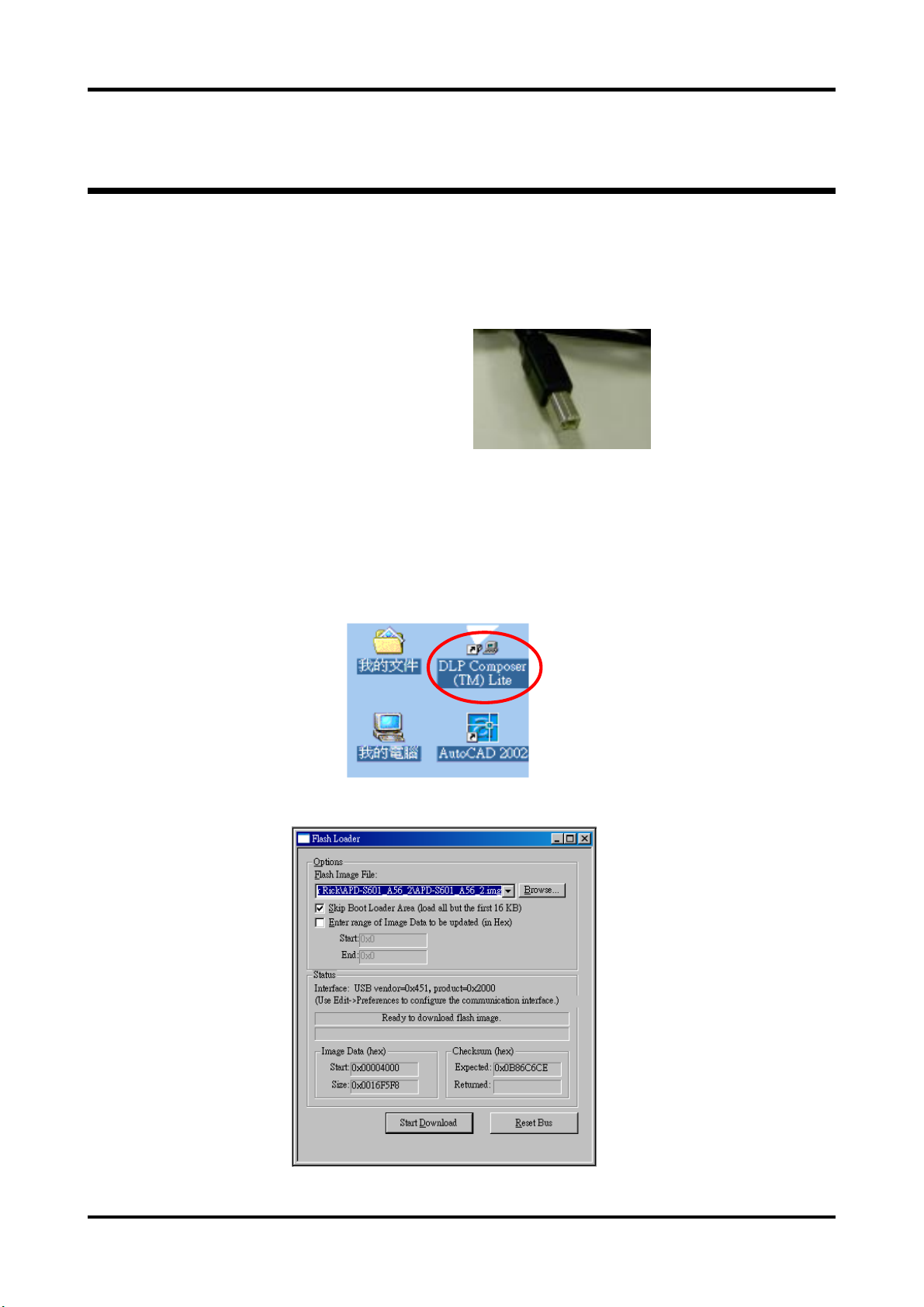
Upgrading Procedure
Chapter 2
1. Connect Download Ca ble to proje ctor
2. Open burning progra mma (DLP Composer Lite)
Chapter 2 8
Page 15
3. Press Power and Menu button together and connect the power cord into the
projector . Tha n release these 2 bottoms .
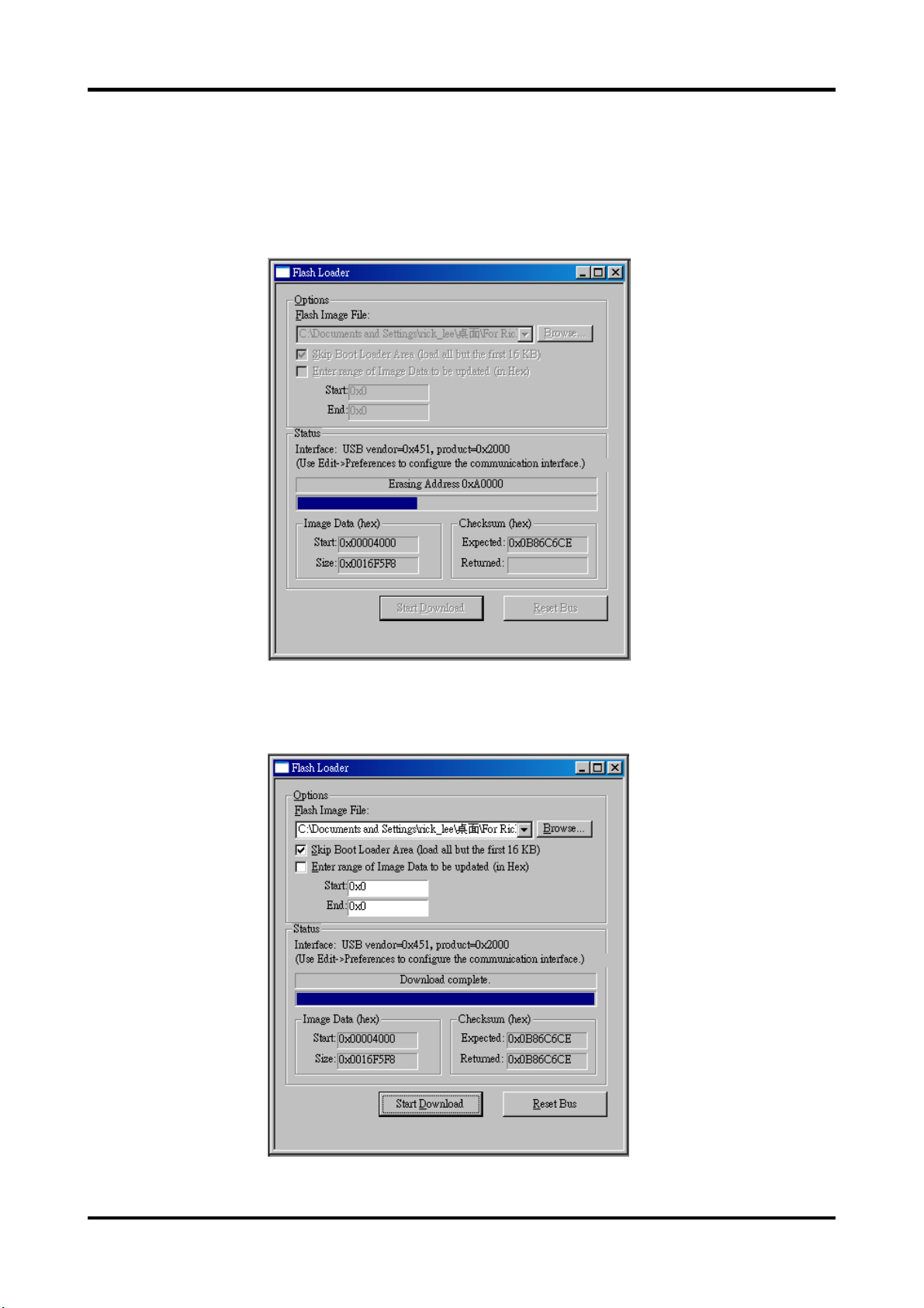
4. Click the Start Download button a nd then start to burning of program .
5. Completion of Burning than remove Power Cord and Burning Cord .
9 Chapter 2
Page 16
Chapter 3
Ma chine Disa sse mbly and Repla cement
This section provides disassembly procedures for PD-113 P DLP Projector. Before you begin any
of these procedures, be sure to turn off the power , computer system, a nd other atta ched devices;
then disconnect the power cable from the electronically outlet. Moreover , when you disa ssemble
the projector , be sure to put the screws in a safe place a nd separate them a ccording to grouping.
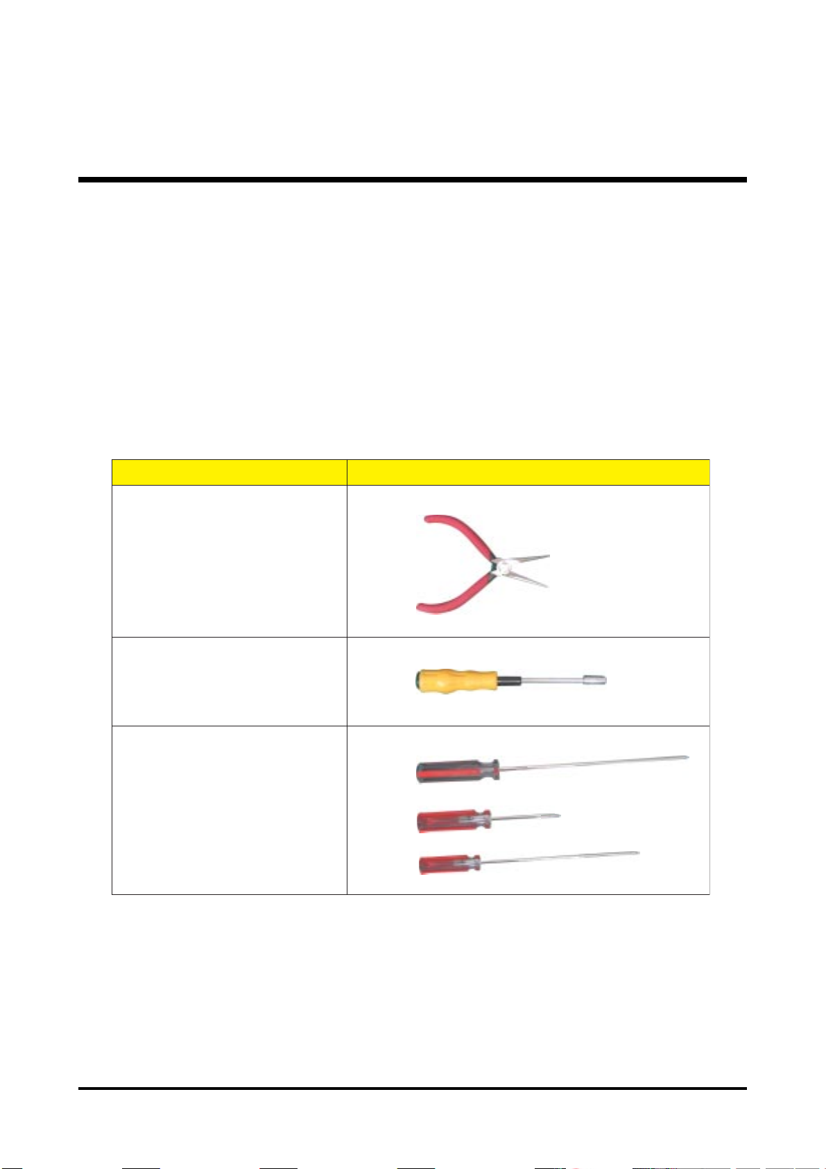
T ool Needed
metI OTOHP
reppiNesoNgnoL
mm5seveelSxeH
701:)+(tiBwercS
101:)+(tiBwercS
201:)+(tiBwercS
Chapter 3 10
Page 17

General Information
Before You Begin
Before proceeding with the disa ssembly procedure, ma ke sure that you do the f ollowing:
1. Turn off the power to the syste m a nd all peripherals.
2. Unplug the AC ada pter a nd all power a nd signal ca bles from the system.
3. W e ar Anti-static wrist strap.
11 Cha pter 3
Page 18

Disa ssemble Lamp Module
P2043-0013
1. Loosen two screws of La mp Cover
2. Remove La mp Cover
3. Loosen two screws of La mp Module .
4. Gra sp the lamp handle a nd pull out La mp Module
p.s Related notice of repla ce lamp pls refer to the Lamp Specification se ction .
Note:Unplug all the cord before disadde mbling the Projector.
Chapter 3 12
Page 19

Disa ssemble IO Cover & Top Cover
1. Loosen the four screws of IO cover.
2. Remove IO cover
3. Loosen the two screws of Back Cover
1. Loosen the two screws of Top Cover.
2. Lift up Top Cover directly (Be careful there is a internal wire connect with the main board)
13 Cha pter 3
Page 20

Disassemble Speaker
P2034-452-99
1. Loosen the two screws of Speaker.
2. Life up Speaker.
Disassemble Front Cover
1. Loosen the two screws of Front Cover.
2. Lift up Front Cover directly(Be careful there are three internal wires connect with the main
board)
Chapter 3 14
Page 21

Disa s semble Front Fan
1. Lift up the Front f Fan Set from front cover directly.
15 Cha pter 3
Page 22

Disa ssemble Front IR Board & IR Cover
1. Loosen the screws of Front IR board
2. Remove the Front IR board.
3. Take out IR Cover dire ctly.
Chapter 3 16
Page 23

Disa sse mble Video IO
1. Loosen the two screws of Back Cover
2. Loosen back cover.
3. Remove the Video IO.
17 Cha pter 3
Page 24

Disa ssemble Main Board
P2247-2001
2447-0100
1. Loosen the four screws of Main Board
2. Un plug all wires on the board (Main Board PIN location of connectors pls refer to
Cha pter 5 )
3. Remove Main Board
Chapter 3 18
Page 25

Disa sse mble Ballast Module & Back IR
1. Loosen the screw of Back IR board.
2. Remove the Ba ck IR board
3. Loosen the six screws of Ballast Module
4. Un plug all wires on Ballast Module (Ballast Board PIN location of connectors pls refer
to Cha pter 5 )
3. Remove the Balla st Module.
19 Cha pter 3
Page 26

Disa sse mble Optical Engine
P2443-0002
1. Loosen the four screws of Optical Engine
2. Remove the Optical Engine ( with Lamp ) .
Chapter 3 20
Page 27

Disassemble Back Cover
1. Loosen the screw of AC Inlet & remove the ring.
2. Remove the Ba ck Cover .
21 Cha pter 3
Page 28

Disassemble Back IR Cover, AC Outlet
1. Take out the AC Inlet.
2. Take out the Ba ck IR Cover .
Chapter 3 22
Page 29

Disa sse mble Power Module
02595-0063-00
1. Unplug the wire.
2. Loosen the five screws of Power Module
3. Remove the Power Module.
23 Cha pter 3
Page 30

Disassemble Mylar & Ground Plate
1. Lift up the Mylar.
2. Then lift up the Groung Plate.
Chapter 3 24
Page 31

Disa sse mble He atsink & DMD Board
1. Loosen the four screws of Heatsink.
2. Tear off the EMI Pad
3. Remove the Heatsink. (Do not Suggest to tear of f Thermal Pa d a nd DMD Pad
on Heatsink unless they are damaged)
4. Lift up the DMD Board.
25 Cha pter 3
Page 32

Disa ssemble DMD Asse mbly & DMD
1. Lift up the DMD Assembly
2. Lift up the DMD
Chapter 3 26
Page 33

Disa sse mble Thermal Board
1. Loosen the screw of SENSOR BRACKET TPD
2. Remove the Thermal Borad
27 Cha pter 3
Page 34

Disa ssemble Optical Engine Fan
02394-0011-00
1. Loosen the three screws of Fan
2. Remove the Optical Engine Fa n
Chapter 3 28
Page 35

Chapter 4
Troubleshooting
This chapter provides technicians and people who have an electronic background a primary
description a bout maintaining the product. Moreover, you can get the appropriate operation
to solve some complicated problems of component repairing and professional problems.
The Trouble shooing section focus on below items:
1. Video Signal T roubleshooting
2. Operation Function Trouble shooing
3. Power Source T roubleshooting
Chapter 4 30
Page 36

Video Signal
Computer
No Signal
Check
Source
OK
Check
Cable
OK
NG
NG
Turn on
Source
Repla ce
Cable
Video
No Signal
Check
Source
OK
Check
Cable
OK
NG
NG
Turn on
Source
Repla ce
Cable
Computer
Mode
Input
OK
Change M ain
Board
NG
Change to
Computer
Mode
Video
Mode
Input
OK
Change Main
Board
NG
Change to
Video Mode
31 Cha pter 4
Page 37

Fail to light up
No V olume
Check
LED indication
OK
Check
Lamp
OK
Check
Thermal
Sensor
NG
NG
NG
Look up user
manual ,a nd
follow indicative action
Replace Lamp
Replace Thermal Sensor
Check
Top cover’s cable
OK
Check
Speaker
Connector
OK
Check
Speaker
NG
NG
NG
Repla ce cable
or connect the
cable ba ck
Speaker
Connector
Become loose
Replace
Speaker
OK
Check
Fan
OK
Check
Main Board
OK
Check
Ballast
NG
NG
NG
Replace Fan
Repla ce Main
Board
Replace
Balla st
OK
Check
Main
Board
OK
Repla ce Main
Chapter 4 32
Page 38

Color Missing
On Screen
OK
C/W Cable
Connector
OK
Check
Cable
OK
Check Main
Board
NG
NG
NG
Check Cable
Connector
Replace
Cable
Change Main
Board
OK
Change Optical
Engine
33 Cha pter 4
Page 39

Operation Function:
Remote Control
Failure
Check
Battery
Level
OK
Check
Remote
Control
OK
NG
Repla ce Battery
NG
Repla ce Remote
Control
Button Failure
Check
Top cover’s cable
OK
Check
Button
OK
NG
NG
Replace cable
or connect the
cable back
Repla ce Button
Check
IR
OK
Main
Board Fail
NG
Repla ce IR
Check
Keypad
OK
Repla ce
Main Board
NG
Replace Keypad
Chapter 4 34
Page 40

Power Source:
No Power Source
After Turning On
Check
La mp Cover
Switch
OK
Check
Power Cord
OK
Check
Top Cover (key
cable..)
NG
Replace Lamp
Cover or
Reassembly
NG
NG
Repla ce
Power Cord
Repla ce
cable or key
Fan failure After
Turning On
Check
Fan
Connector
OK
Check
Inner
Wires
OK
Check
Fan
NG
NG
NG
Fan Connector
Become loose
Replace Inner
Wires
Replace
Fan
OK
Check
Main
Board
OK
Check
Power
Board
OK
Repla ce Standby
Signal cable NG
NG
NG
Replace M ain
Board
Repla ce
Power Board
OK
Check
Main
Board
OK
Replace Power
Baord
NG
Repla ce
Main Board
35 Cha pter 4
Page 41

Function Test and Alignment
Equipment Needed
Test Condition
Chapter 4 36
Page 42

Test Display Modes and Patterns
Compatible Modes
langiSteserP cnyS noituloseR )zH(Vf )zH(Hf
065.13
AGV)-(V,)+(H008x046
AGVS)+(V,)-(H006x008
AGX)-(V,)-(H867x4201
AGXS)+(V,)+(H4201x08210646
277.73
575.73
583.34
651.53
069.73
271.84
579.64
587.35
064.84
075.65
5706
0846
583.86
37 Cha pter 4
Page 43

Function Test Display Pattern
metI tnetnoCtseT nrettaP noitacificepS krameR
1pukcehcesioN
2pukcehctsuDkcalBlluF
3pukcehctsuDetihWlluF
4pukcehcnoituloseR
5pukcehcrolocBGRBGR652
6pukcehctsuDyarGlluF
7
pu
kcehcegakaelthgiL
emarF
PMB"serauqs21"ehttceleS.)1(
serauqs21
.rotcejorp
serauqs21
.serauqseerht
rekcilf008
.rekcilf
dnakcalB
droWetihW
sidrowhcaeerus
.snoitidnoc
.elifehtforeddal
yradnuoB
.elifPMB
ynasierehtfikcehcotelif
foegatsehtgnirudsesion
ehtpugnimrawdna,nogninrut
ehtnoraeppasesionehT.)2(
nahtsselebdluohserauqs
PMB"rekcilf008"ehttceleS.)3(
nodrowhcaeterusekaM.elif
tonnseodegamidetcejorpeht
elifPMB"kcalBlluF"ehttceleS)1(
ehtnoegamiehttcejorpot
timorfsretem8.1dnatS.neercs
.sniatsoneraerehterusnedna
elifPMB"etihWlluF"ehttceleS)1(
ehtnoegamiehttcejorpot
timorfsretem8.1dnatS.neercs
.sniatsoneraerehterusnedna
etihwdnakcalb"ehttceleS)1(
ehtesU.elifPMB"drow
detcejorpehttsujdaotrotcejorp
ezismumixamehtotegami
htobrednuelbahsiugnitsid
ehtnoegamiehttcejorpot
ekamdnaezismuminimdna
elifPMB"BGR652"ehttceleS)1(
foreddalrolocehtfikcehcot
rolocehtsehctamegamieht
,elifPMB"emarFyradnuoB
ehtnonottubOTUAehtsserp
egamidetcejorpehtfosroloc
ehtnodetneserpsaraelcera
Fi erug5
elifPMB"yarGlluF"ehttceleS)1(
timorfsretem8.1dnatS.neercs
.sniatsoneraerehterusnedna
"ehttceles,redlofehtnokcilC)1(
dnasenilehtfikcehc,rotcejorp
1erugiF
1erugiF
2erugiF
3erugiF
4erugiF
erugiF6
7erugiF
8erugiF
12 squares Pattern (Figure 1) 800 flicker Pattern (Figure 2)
Chapter 4 38
Page 44

Full Black Pattern (Figure 3) Full White Pattern (Figure 4)
Black and White Word Pattern (Figure 5) 256RGB Pattern (Figure 6)
Gray Pattern (Figure 7) Boundary Frame (Figure 8)
39 Cha pter 4
Page 45

Chapter 5
Connector Information
Introduction
This section provides ea ch conne ctor location on boards, signal and function of each
board. They will be useful for your detecting the defective boards.
Main Board
Summarize
rotcennoC noitpircseD
1NCRI
2NClortnocdapyeK
3NCnaF
4NCnaF
5NCnaF
6NCnaF
7NCRI
1JlortnoctsallaB
3JnioediV-S&oidiV
5JrotcennocDMD
7JR-oeretskcajenohP
8JleehwroloC
9JnirewoP
51JnioediV-S&oidiV
1PJBSU
3PJxedniWC
5PJnurybdnatS
1NOCBUS-D
2NOCoediV
3NOCoediv-S
Chapter 5 40
Page 46

The Locations of Connectors
FLAG
GND
3.3V
CN1 , CN7 : IR
CN3 , CN4 , Cn5 : FAN
#NIP noitpircseD
1
2
3
J1 :Balla st Control
MWP
lortnoC
DNG
41 Cha pter 5
Page 47

CN2 : Keypad Control
Chapter 5 42
Page 48

J3 , J15 : Video & S-Videop IN
CON3 : S-Video
CON2 : Video
43 Cha pter 5
Page 49

CON1 : D_SUB
J7 : Phone jack Stereo-R
J8 : Color Wheel
Chapter 5 44
Page 50

J9 : Power Supply
Stand by Run
STBY_CTRL
GND
JP1 : USB
JP3 : CW Index
JP3 : CW Index
45 Cha pter 5
Page 51

Power Board
Summarize
The Locations of Connectors
CN101 : AC Inout
46 Chapter 5
Page 52

CN201 : +380V Output
CN301 :DC Output
Chapter 5 47
Page 53

Balla ster Board
Summarize
The Locations of Connectors
CN1 : Power supply
CN2 : Control signal
48 Chapter 5
Page 54

Chapter 6
FRU (Field Repla ce a ble Unit) List
This chapter gives you FRU ( Field Replaceable Unit ) listing in global configuration of PD-113P.
Refer to this chapter whenever ordering for parts to repair or for RMA ( Return Merchandise
Authorization ). Plea se note that WHEN OR DERING FRU PARTS, you should check the most
up-to-date information available on your regional web or cha nnel. For whatever re a son s a part
number change is ma de, it will not be noted on the printed Service Guide. For Acer AUTHORIZED SER VICE PROVIDERS, Acer office may have a DIFFERENT part number code from
those given in the FRU list of this printed Service Guide. You MUST use the local FRU list provided by your regional Acer office to order FRU parts for repair a nd service of customer machines.
NOTE : To scrap or to return the defective parts, you should follow the local government
ordina nce or regulations on how to dispose it properly, or follow the rules set by your
regional Acer office on how to return it.
Chapter 6 49
Page 55

FRU List
P2447-0100
P2443-0016
02595-0063-00
Power Cable
Wire 12 Pin
M/B to Power
P2084-0004
50 Chapter 6
Page 56

Chapter 6 51
P2443-0002
Optical Engine
( w/o lamp)
P1943-0014
Page 57

52 Chapter 6
02595-0029-00
02394-0011-00
02595-0014-00
Wire 12 Pin
M/B to Power
Wire 2 Pin
Ballast to Power
02595-0019-00
Page 58

Chapter 6 53
02595-0030-00
02595-0063-00
Power cable
 Loading...