

Page 1
Acer PD113
Service Guide
Service guide files and updates are available
on the CSD web; for more information,
please refer to http://csd.acer .com.tw
100% Recycled Paper
Page 2

Copyright
Copyright © 2004 by Acer Incorporated. All rights reserved. No part of this publication
may be reproduced, transmitted, transcribed, stored in a retrieval system, or translated
into any language or computer language, in any form or by any means, electronic,
mechanical, magnetic, optical, chemical, manual or otherwise, without the prior written
permission of Acer Incorporated.
Disclaimer
The information in this guide is subject to change without notice.
Acer Incorporated makes no representations or warranties, either expressed or
implied, with respect to the contents here of and specifically disclaims any warranties
of merchantability or fitness for any particular purpose. Any Acer Incorporated software
described in this manual is sold or licensed “as is”. Should the programs prove defec
tive following their purchase, the buyer (and not Acer Incorporated, its distributor, or its
dealer) assumes the entire cost of all necessary servicing, repair , and any incidental or
consequential damages resulting from any defect in the software.
Acer is a registered trademark of Acer Corporation.
I ntel is a registered trademark of Intel Corporation.
Pentium and Pentium I I/III are trademarks of Intel Corporation.
Other brand and product names are trademarks and/or registered trademarks of their respective holders.
Page 3
Conventions
The following conventions are used in this manual
Screen messages Denotes actual messages that appear on screen.
Note
Warning
Caution
Important
Gives bits and pieces of additional information
related to the current topic.
Alerts you to any damage that might result from
doing or not doing specific actions.
Gives precautionary measures to avoid possible
hardware or software problems.
Reminds you to do specific actions relevant to the
accomplishment of procedures.
Page 4

Preface
Before using this information and the product it supports, please read the following
general information.
1. This Service Guide provides you with all technical information relating to the BASIC
CONFI GURATION decided for Acer’s “global” product offering. To better fit local
market requirements and enhance product competitiveness, your regional office MAY
have decided to extend the functionality of a machine (e.g. add-on card, modem, or
extra memory capability). These LOCALI ZED FEATURES will NOT be covered
in this generic service guide. I n such cases, please contact your regional offices or the
responsible personnel/channel to provide you with further technical details.
2. Please note WHEN ORDERI NG FRU PARTS, that you should check the most up to-date information available on your regional web or channel. I f, for whatever reason,
apart number change is made, it will not be noted in the printed Service Guide. For
ACER-AUTHORIZED SERVICE PROVIDERS, your Acer office may have a DIFFER
ENT part number code to those given in the FRU list of this printed Service Guide.
You MUST use the list provided by your regional Acer office to order FRU parts for
repair and service of customer machines.
Page 5

Table of Contents
Chapter 1 System Introduction 1
Technical Specification .......................................................................................................1
Lamp Specification............................................................................................................. 2
System Block Diagram .......................................................................................................6
Optics Conceptual Drawing................................................................................................7
Chapter 2 Firmware Update 8
Setup Tool / Equipment.......................................................................................................8
Upgrading Procedure .........................................................................................................8
Chapter 3 Machine Dissassembly and Replacement 10
General I nformation ..........................................................................................................11
Disassemble Lamp Module..............................................................................................12
Disassemble IO Cover & Top Cover................................................................................13
Disassemble Speaker & Front Cover ..............................................................................14
Disassemble Front Fan...................................... ..............................................................15
Disassemble Front IR Board & IR Cover.........................................................................16
Disassemble Video IO .......................................................................................................17
Dissassemble Main Board..... ..........................................................................................18
Disassemble Ballast Module & Back IR...........................................................................19
Disassemble Optical Engine.............................................................................................20
Disassemble Back Cover................................................................................................. 21
Disassemble Back IR Cover , AC Outlet......................................................................... 22
Disassemble Power Module............................................................................................ 23
Disassemble Ground Plate & mylar............................................................................... 24
Disassemble Heatsink & DMD Board........................................................................... 25
Disassemble DMD Assembly & DMD........................................................................... 26
Disassemble Thermal Board.......................................................................................... 27
Disassemble Optical Engine Fan.................................................................................... 28
Exploded Overview...........................................................................................................29
Page 6

Table of Contents
Chapter 4 Trouble shooting 30
Video Signal troubleshooting.............................................................................................31
Operation FunctionTroubleshooting..................................................................................34
Power SourceTroubleshooting..........................................................................................35
Function Test and Alignment...............................................................................................36
Equipment Needed...................................................................................................36
Test Condition............................................................................................................36
Test Display Modes and Patterns .....................................................................................37
Compatible Modes ..................................................................................................37
Function Test Display Pattern..................................................................................38
Chapter 5 Connector Information 40
Introduction...........................................................................................................................40
Main Board......................................................................................................................... 40
Power Board .....................................................................................................................47
Ballast Board ......................................................................................................................49
Chapter 6 FRU(FieldReplaceable Unit) List 50
FRU List...............................................................................................................................51
Page 7

Syste m Introduction
1
Technical Specification
Item Description
Display Type Single Chip DLP Projector
Lamp Type 200W
Brightness 1600 Lumen
Contrast Ratio 2000 : 1(Full on / off) (Min)
Resolution(Pixels) 800 x 600
Uniformity 90%
Chapter
Optical Compensation Light Tunnel
Focal Length 20.2 ~ 24.2 mm
Screen Size 27.5~330 inches
Throw Distance 1.2 ~ 12 Meter
Compatibility
Operation Humidity 80%
Operation Temperature +5 ~ +35C
Sound Noise 30dB(A)(standard mode)/27db(A) (ECO mode)
Power Requirement 100~240v, 50~60Hz
Dimensions ( W x H x D ) 256 x 198 x 92 mm
Weight 2.0 KG (<4.5 lb)
"Horizontal frequency (31~79KHz" )
"Vertical frequency ( 50~85Hz" )
Certification CE Class B, FCC Class B , VCCI-II , UL , cUL
1 Cha pter 1
Page 8

Lamp Specification
1.Product Scope
The product is a lamp system consi sting of a short arc burner within a reflector, and an
electric lamp ballast.
Lamp type NUPNUA200TPR/A
Driver type NUPNSA200TPR/A
2. Product Specifications : NUPNUA200TPR/A
2.1 Dimensions
Lamp see 2.6 figure (lamp drawing)
Overall length 66.6
Arc length 1.1mm(typical)
Reflector type Elliptical
Lamp weight man. 75g
2.2 Marking on the lamp
Position of marking On ceramic and reflector
Lot number NUPNUA200TPR/A
Type no. Serial number(ex. A1234)
2.3 Operating and measurement conditions
Ballast type Test conditions stable at 200W with
NUPNUA200TPR/A
Rated lamp wattage 200W
Lamp position Horizontal (within 15 degree to horizontal optical axis)
Cha pter 1 2
Page 9

2.4 Ignition performance
Rise time
50% of the stabilized illuminance is less than 60 second after turning on cooling lamp .
Hot restrike
I f the lamp unit has been off for more than 60 sec. the lamp available of restrike .
Lamp power at ignition
Rated power(200W)
Power switch
Power switch to reduceds power (170W) recommends changing after 2 minutes
from lamp ignition .
2.5 Optical characteristics
Based on meansurement on standard optical unit by NEC Lighting
Luminosity(initial) typ. 13000 lm
min. 11930 lm
Color coordinates x : 0.3 +/- 0.02
y : 0.32 +/- 0.02
Flickering and arc jump less than 5 %
The flicker and arc jump over than 5% should be less than 10 times during 10 minutes
operation
Lamp Decay chart
Lumen
1600
1500
1400
1300
1300
1200
1100
1000
Ansi/Lumen
900
800
700
600
0 73~96 145~192 298~393 490~535 697~742
1217
1186
1267
1200
1139
1090
1088
1053
991
993 996
Test time/h
3 Cha pter 1
Page 10
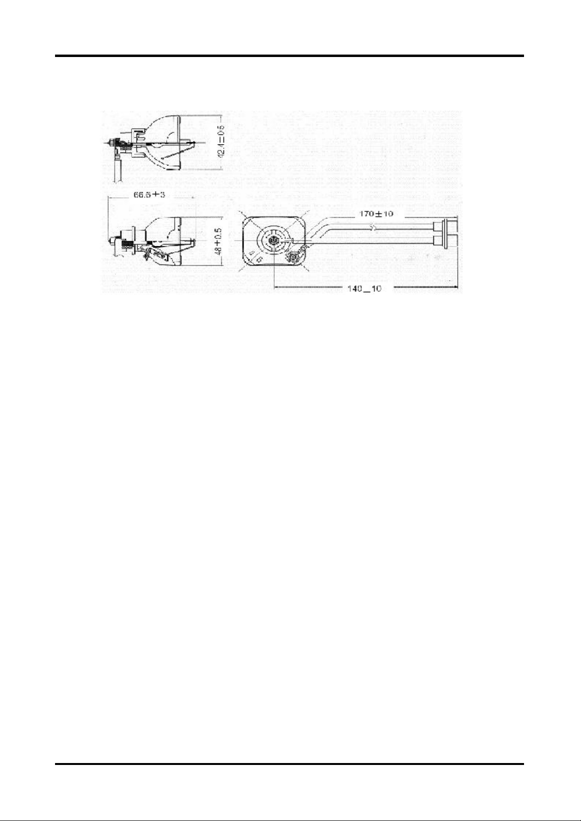
2.6 Lamp drawing
2.7 Instructions for use
1. The lamp becomes high temperature after turning off the projector with the power
button. I f you touch the lamp, you may scald your finger. When you replace the lamp,
wait for at least 45 minutes for the lamp to cool down.
2. Do not touch the lamp glass at any time. The lamp may explode due to improper
handling, including the touching of the lamp glass.
3. Lamp lifetime may differ from lamp to lamp and according to the environment of use.
There is no guarantee of the same lifetime for each lamp. Some lamps may fail or
terminate their lifetime in a shorter period of time than other similar lamps.
4. A lamp may explode as a result of vibration, shock or degradation as a result of hours
of use as its lifetime draws to an end. Risk of explosion may differ according to the
environment or conditions in which the projector and lamp are being used.
5. Wear protective gloves and eyeglasses when fixing or detaching the lamp.
6. Faster on-off-cycles will damage the lamp and reduce lamp life. Wait at least for 5
minutes to turn off the projector after powering on.
7. Do not operate the lamp in proximity to paper, cloth, or other combustible material nor
cover it with such materials. Otherwise it could cause a fire.
Cha pter 1 4
Page 11

8. Do not operate the lamp in an atmosphere containing an inflammable substance, such
as thinner . Otherwise it could cause a fire or explosion.
9. Thoroughly ventilate the area or the room when operating the lamp in an oxygen
atmosphere (in the air). I f ozone is inhaled, it could cause headaches, nausea,
dizziness, etc.
10. The inorganic mercury is involved in the lamp. I f the lamp bursts, the mercury inside the
lamp will go out of the projector . Leave the area immediately if the lamp shatters while
being operated and ventilate the area for at least 30 minutes in order to avoid the
inhalation of mercury fumes. Otherwise it could be harmful to user’s health.
11. Dispose of the used lamp according to local regulations.
12. Ensure that screws are tightened properly. Screws not tightened fully may result in
injury or accidents.
13. Since the lamp is made of glass, do not drop the unit and do not scratch the glass.
14. Do not reuse the old lamp. This could cause the lamp to explode.
15. Be sure to turn off the projector and unplug the AC power cord before replacing the
lamp.
16. Do not use the projector with the lamp cover removed.
Disposal : For disposal of spent lamps, always consult federal, state, local and
provincial hazardous waste disposal rules and regulations to ensure
proper disposal.
Caution : This lamp emits ultra violet (UV) radiation and operates at high
pressure.
This lamp may only be used in enclosed fixtures that comply with
UL1572.
Due to the high luminous efficacy, the UV radiation which the lamp
emits and the high pressure within the lamp, P-VI Pâ lamps may only be
operated within enclosed, purpose-built housings.
5 Cha pter 1
Page 12
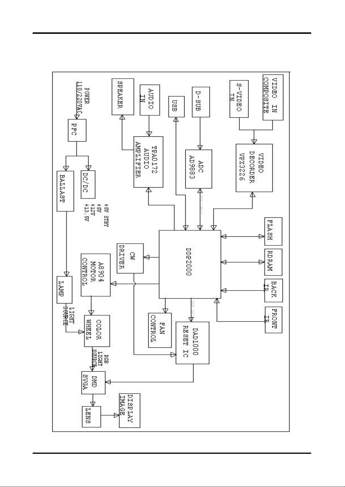
System Block Diagram
Cha pter 1 6
Page 13
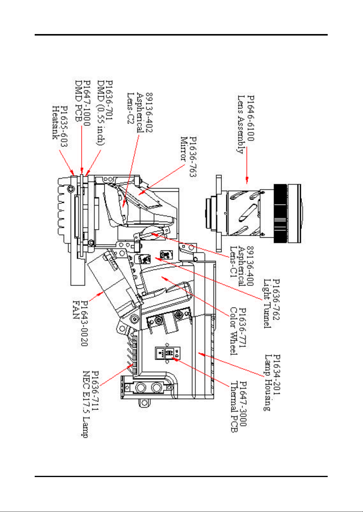
Optics-Conceptual Draw ing
7 Cha pter 1
Page 14
Firmwa re Upgrade
This chapter provides the equipment needed, setup and upgrading procedure for
Firmware upgrade.
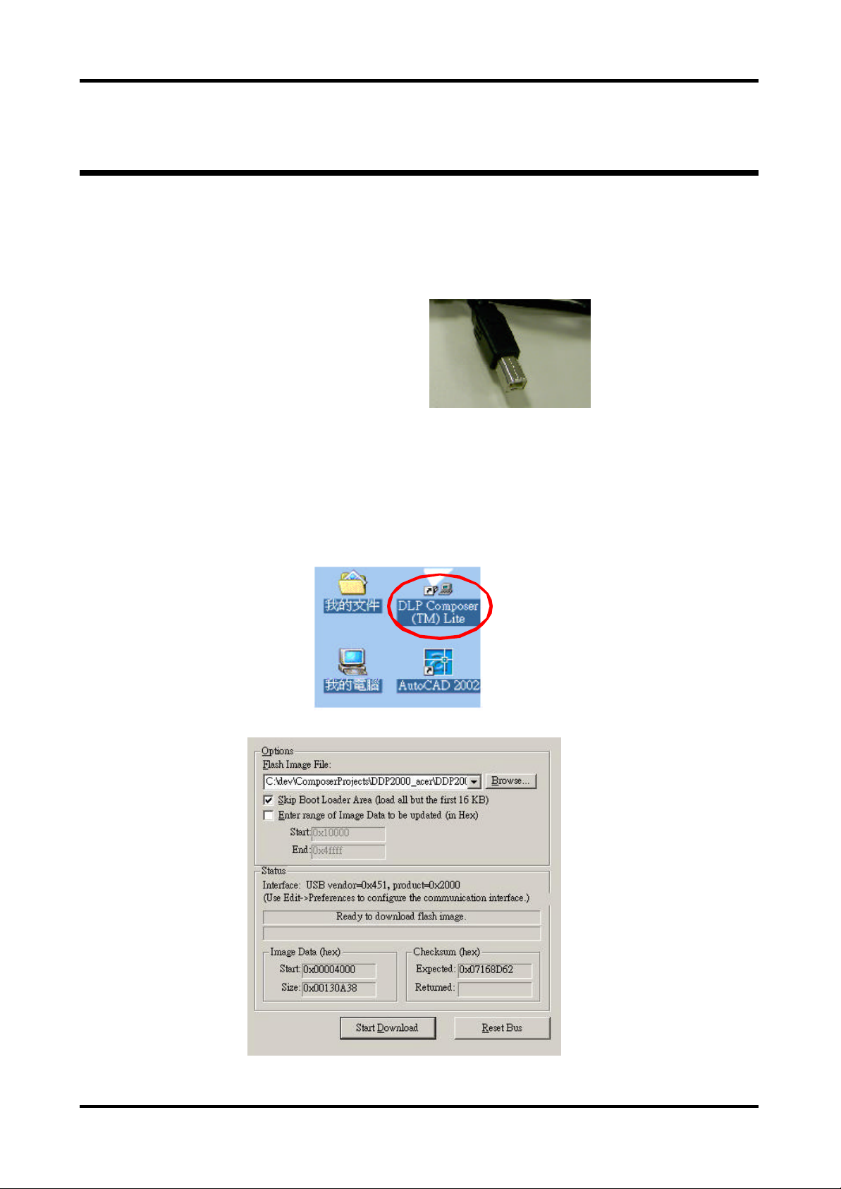
Setup Tool / Equipment
1. Computer
2. USB Cable (see right picture)
3. Power Coard
U pgrading Procedure
Chapter 2
1. Connect Download Cable to projector
2. Open burning programma (DLP Composer Lite)
Cha pter 2 8
Page 15
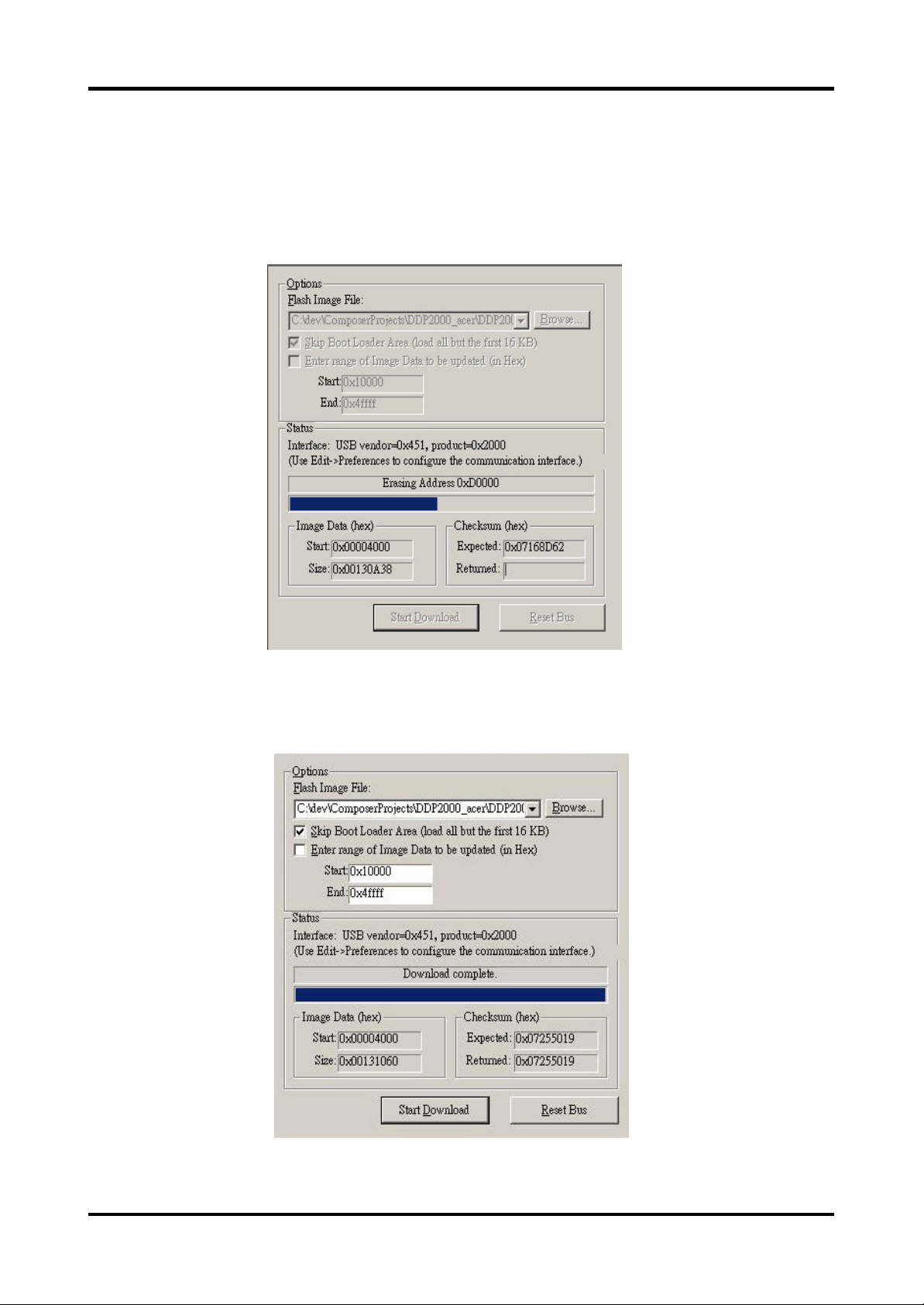
3. Press Power and Menu button together and connect the power cord into the
projector . Than release these 2 bottoms .
4. Click the Start Download button and then start to burning of program .
5. Completion of Burning than remove Power Cord and Burning Cord .
9 Cha pter 2
Page 16
Chapter
3
Ma chine Disassembly and Replacement
This secti on provides disassembly procedures for PD-113 DLP Projector. Before you begin
any of these procedures, be sure to turn off the power , computer system, and other attached
devi ces; then disconnect the power cable from the electronically outlet. Moreover, when you
disassemble the projector, be sure to put the screws in a safe place and separate them according to grouping.
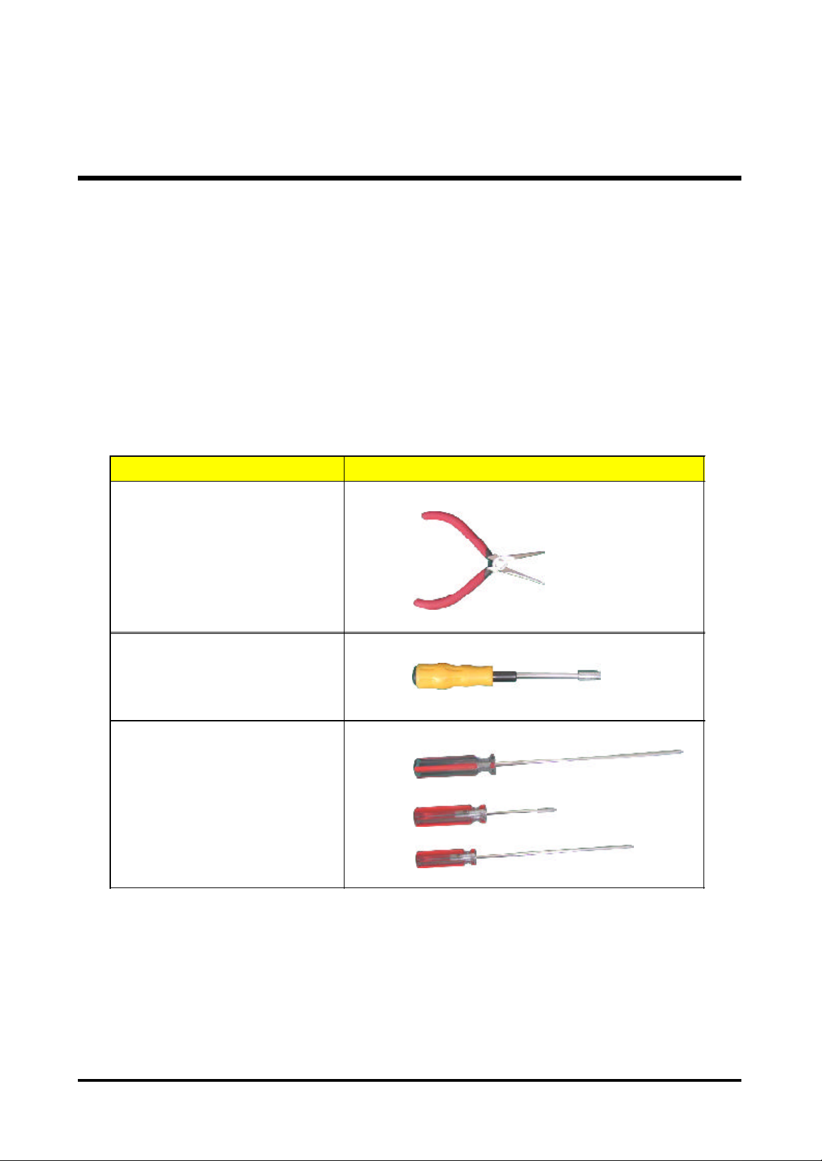
Tool Needed
Long Nose Nipper
Hex Sleeves 5mm
Screw Bit (+) : 107
Screw Bit (+) : 101
Screw Bit (+) : 102
Item PHOTO
Cha pter 3 10
Page 17

General Information
Before You Begin
Before proceeding with the disassembly procedure, make sure that you do the following:
1. Turn off the power to the system and all peripherals.
2. Unplug the AC adapter and all power and signal cables from the system.
3. Wear Anti-static wrist strap.
11 Cha pter 3
Page 18
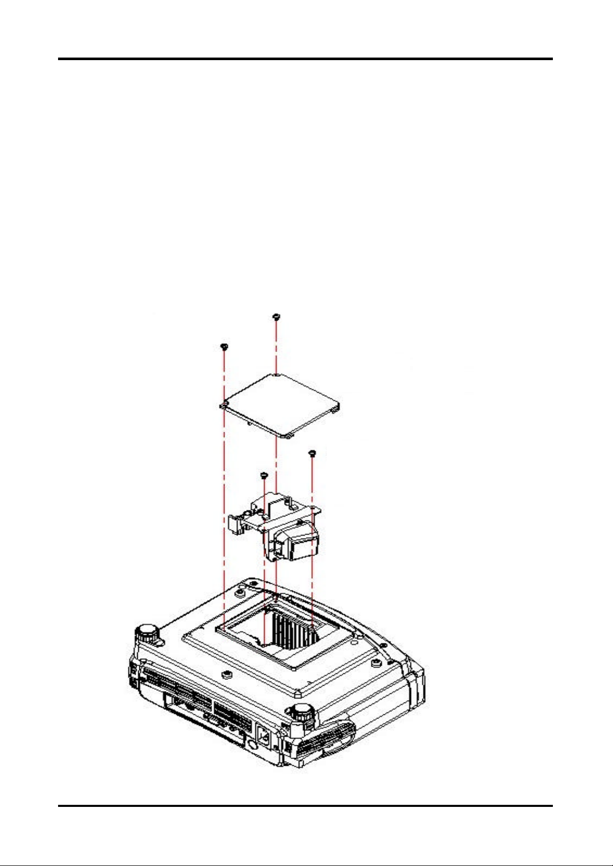
Disassemble Lamp Module
1. Loosen the two screws of Lamp Cover
2. Remove Lamp Cover
3. Loosen two screws of Lamp Module .
4. Grasp the lamp handle and pull out Lamp Module
p.s Related notice of replace lamp pls refer to the Lamp Specification section .
Note:Unplug all the cord before disaddembling the Projector.
01635-366*2
P0243-0013
Lamp Cover Assembly
01635-366*2
P2084-0006
Lamp Assembly
Cha pter 3 12
Page 19

Disassemble IO Cov er & Top Cover
1. Loosen the four screws of I O cover.
2. Remove I O cover
3. Loosen the two screws of Back Cover
P2035-051
01635-B73-N *2
01635-B73-N *2
82035-251 *2
1. Loosen the two screws of Top Cover .
2. Lift up Top Cover directly (Be careful there is a internal wire connect with the main board)
P2084-0001
01635-D11-N *2
13 Cha pter 3
Page 20

Disassemble Speaker
1. Loosen the two screws of Speaker .
2. Life up Speaker .
01635-362 *2
02413-0016-00
02591-0014-00
Disassemble Front Cov er
1. Loosen the two screws of Front Cover.
2. Lift up Front Cover directly(Be careful there are three internal wires connect with the main
board)
P2084-0004
01635-B73-N *2
Cha pter 3 14
Page 21

Disassemble Front Fan
1. Lift up the Front Fan Set from front cover directly.
P2043-0006
15 Cha pter 3
Page 22

Disassemble Front IR Board & IR Cov er
1. Loosen the screw of Front I R Board
2. Remove the Front I R Board
3. Take out IR Cover directly.
P2034-456
P2084-0004
01635-361
02595-0029-00
P2047-1001
Cha pter 3 16
Page 23

Disassemble Video IO
1. Loosen the two screws of Back Cover
2. Loosen back cover .
3. Remove the Video I O.
01635-361 *2
17 Cha pter 3
Page 24

Disassemble Main Board
1. Loosen the four screws of Main Board
2. Unplug all wires on the board (Main Board PI N location of connectors pls refer to
Chapter 5 )
3. Remove Main Board
01635-366 *4
P1684-0000
Cha pter 3 18
Page 25

Disassemble Ballast Module & Back IR
1. Loosen the screw of Back I R board.
2. Remove the Back I R board
3. Loosen the six screws of Ballast Module
4. Unplug all wires on Ballast Module (Ballast Board PI N location of connectors pls refer
to Chapter 5 )
5. Remove the Ballast Module.
01635-361 *2
01635-A44-N
P1647-5001
01635-366 *4
P2084-0005
Unplug from Lamp Module Connector
Unplug from Power Module 2 Pin Connector
19 Cha pter 3
Page 26

Disassemble Optical Engine
1. Loosen the four screws of Optical Engine
2. Remove the Optical Engine .
01635-A01 *4
P2084-0007
Cha pter 3 20
Page 27

Disassemble Back Cov er
1. Loosen the screw of AC Inlet & remove the ring.
2. Unplug the wire.
3. Remove the Back Cover .
02595-0028-00
01635-A08
01635-705
21 Cha pter 3
Page 28

Disassemble Back IR Cov er, AC Outlet
1. Take out the AC Inlet.
2. Take out the B ack I R Cover.
P1634-462
02595-0028-00
P2084-0003
Cha pter 3 22
Page 29

Disassemble Pow er Module
1. Unplug the wire.
2. Loosen the five screws of Power Module
3. Remove the Power Module.
02595-0014-00
01635-361 *5
P1684-0007
23 Cha pter 3
Page 30

Disassemble Ground Plate & Mylar
1. Lift up the Mylar.
2. Then lift up the Ground Plate.
P2038-052
P2084-0002
P2035-050
Cha pter 3 24
Page 31

Disassemble H eatsink & DMD Board
1. Loosen the four screws of Heatsink.
2. Tear off the EMI Pad
3. Remove the Heatsink. (Do not Suggest to tear off Thermal Pad and DMD Pad
on Heatsink unless they are damaged)
4. Lift up the DMD Board.
83034-040
P1638-106*2
01635-C01 *4
P1635-603
P1647-1000
P1638-105
25 Cha pter 3
Page 32

Disassemble DMD Assembly & DMD
1. Lift up the DMD Assembly
2. Lift up the DMD
P1636-701
right angle to
right angle
02475-0003-10
DMD Assembly
Cha pter 3 26
Page 33

Disassemble Thermal Board
1. Loosen the screw of Thermal Board
2. Remove the Thermal Borad
01635-353
P1647-3000
02595-0017-00
27 Cha pter 3
Page 34

Disassemble Optical Engine Fan
1. Loosen the three screws of Fan
2. Remove the Optical Engine Fan
P1638-102
stick on top of joint
and can not protrude
this side
P1643-0020
P0335-101 *3
screw the two
screws first
Cha pter 3 28
Page 35

Exploded Ov erview
P2084-0001
01635-366*4
P1684-0000
P2084-0004
01635-D11-N*2
P2043-0006
01635-361*2
01635-361*5
P2038-052
P2035-050
01635-366*3
P2084-0005
P2084-0007
P1684-0007
P1635-056
01635-B73-N *2
01635-B77*2
82035-251*2
P2034-464
P2034-454-99
02595-0028-00
P2084-0003
01635-B73-N*2
P2034-456
P2034-454-99
01635-366*2
P2084-0002
P2043-0018*2
29 Cha pter 3
Page 36

Chapter 4
Troubleshooting
This chapter provides technicians and people who have an electronic background a primary
description a bout maintaining the product. Moreover, you can get the appropriate operation
to solve some complicated problems of component repairing and professional problems.
The Trouble shooing section focus on below items:
1. Video Signal Troubleshooting
2. Operation Function Trouble shooing
3. Power Source Troubleshooting
Chapter 4 30
Page 37

Video Signal
Computer
No Signal
Check
Source
OK
Check
Cable
OK
NG
NG
Turn on
Source
Repla ce
Cable
Video
No Signal
Check
Source
OK
Check
Cable
OK
NG
NG
Turn on
Source
Repla ce
Cable
Computer
Mode
Input
OK
Change M ain
Board
NG
Change to
Computer
Mode
Video
Mode
Input
OK
Change Main
Board
NG
Change to
Video Mode
31 Chapter 4
Page 38

Fail to light up
No V olume
Check
LED indication
OK
Check
Lamp
OK
Check
Thermal
Sensor
NG
NG
NG
Look up user
manual ,a nd
follow indicative action
Replace Lamp
Replace Thermal Sensor
Check
Top cover’s cable
OK
Check
Speaker
Connector
OK
Check
Speaker
NG
NG
NG
Repla ce cable
or connect the
cable ba ck
Speaker
Connector
Become loose
Replace
Speaker
OK
Check
Fan
OK
Check
Main Board
OK
Check
Ballast
NG
NG
NG
Replace Fan
Repla ce Main
Board
Replace
Balla st
OK
Check
Main
Board
OK
Repla ce Main
Chapter 4 32
Page 39

Color Missing
On Screen
OK
Check
Cable
OK
C/W Cable
Connector
OK
Check Main
Board
NG
NG
NG
Replace
Cable
Check Cable
Connector
Change Main
Board
OK
Change Optical
Engine
33 Chapter 4
Page 40

Operation Function:
Remote Control
Failure
Check
Battery
Level
OK
Check
Remote
Control
OK
NG
Repla ce Battery
NG
Repla ce Remote
Control
Button Failure
Check
Top cover’s cable
OK
Check
Button
OK
NG
NG
Replace cable
or connect the
cable back
Repla ce Button
Check
IR
OK
Main
Board Fail
NG
Repla ce IR
Check
Keypad
OK
Repla ce
Main Board
NG
Replace Keypad
Chapter 4 34
Page 41

Power Source:
No Power Source
After Turning On
Check
La mp Cover
Switch
OK
Check
Power Cord
OK
Check
Top Cover (key
cable..)
NG
Replace Lamp
Cover or
Reassembly
NG
NG
Repla ce
Power Cord
Repla ce
cable or key
Fan failure After
Turning On
Check
Fan
Connector
OK
Check
Inner
Wires
OK
Check
Fan
NG
NG
NG
Fan Connector
Become loose
Replace Inner
Wires
Replace
Fan
OK
Check
Main
Board
OK
Check
Power
Board
OK
Repla ce Standby
Signal cable NG
NG
NG
Replace M ain
Board
Repla ce
Power Board
OK
Check
Main
Board
OK
Replace Power
Baord
NG
Repla ce
Main Board
35 Chapter 4
Page 42

Function Test and Alignment
Equipment Needed
Test Condition
Chapter 4 36
Page 43

Test Display Modes and Patterns
Compatible Modes
langiSteserP cnyS noituloseR )zH(Vf )zH(Hf
065.13
AGV)-(V,)+(H008x046
AGVS)+(V,)-(H006x008
AGX)-(V,)-(H867x4201
AGXS)+(V,)+(H4201x08210646
277.73
575.73
583.34
651.53
069.73
271.84
579.64
587.35
064.84
075.65
5706
0846
583.86
37 Chapter 4
Page 44

Function Test Display Pattern
metI tnetnoCtseT nrettaP noitacificepS krameR
1pukcehcesioN
2pukcehctsuDkcalBlluF
3pukcehctsuDetihWlluF
4pukcehcnoituloseR
5pukcehcrolocBGRBGR652
6pukcehctsuDyarGlluF
7
pu
kcehcegakaelthgiL
emarF
PMB"serauqs21"ehttceleS.)1(
serauqs21
.rotcejorp
serauqs21
.serauqseerht
rekcilf008
.rekcilf
dnakcalB
droWetihW
sidrowhcaeerus
.snoitidnoc
.elifehtforeddal
yradnuoB
.elifPMB
ynasierehtfikcehcotelif
foegatsehtgnirudsesion
ehtpugnimrawdna,nogninrut
ehtnoraeppasesionehT.)2(
nahtsselebdluohserauqs
PMB"rekcilf008"ehttceleS.)3(
nodrowhcaeterusekaM.elif
tonnseodegamidetcejorpeht
elifPMB"kcalBlluF"ehttceleS)1(
ehtnoegamiehttcejorpot
timorfsretem8.1dnatS.neercs
.sniatsoneraerehterusnedna
elifPMB"etihWlluF"ehttceleS)1(
ehtnoegamiehttcejorpot
timorfsretem8.1dnatS.neercs
.sniatsoneraerehterusnedna
etihwdnakcalb"ehttceleS)1(
ehtesU.elifPMB"drow
detcejorpehttsujdaotrotcejorp
ezismumixamehtotegami
htobrednuelbahsiugnitsid
ehtnoegamiehttcejorpot
ekamdnaezismuminimdna
elifPMB"BGR652"ehttceleS)1(
foreddalrolocehtfikcehcot
rolocehtsehctamegamieht
,elifPMB"emarFyradnuoB
ehtnonottubOTUAehtsserp
egamidetcejorpehtfosroloc
ehtnodetneserpsaraelcera
Fi erug5
elifPMB"yarGlluF"ehttceleS)1(
timorfsretem8.1dnatS.neercs
.sniatsoneraerehterusnedna
"ehttceles,redlofehtnokcilC)1(
dnasenilehtfikcehc,rotcejorp
1erugiF
1erugiF
2erugiF
3erugiF
4erugiF
erugiF6
7erugiF
8erugiF
12 squares Pattern (Figure 1) 800 flicker Pattern (Figure 2)
Chapter 4 38
Page 45

Full Black Pattern (Figure 3) Full White Pattern (Figure 4)
Black and White Word Pattern (Figure 5) 256RGB Pattern (Figure 6)
Gray Pattern (Figure 7) Boundary Frame (Figure 8)
39 Chapter 4
Page 46

Chapter
5
Connector Information
Introduction
This section provides each connector location on boards, signal and function of each
board. They will be useful for your detecting the defective boards.
Main Board
Summarize
Connector Description
CN1 IR
CN2 Keypad control
CN3 Fan
CN4 Fan
CN5 Fan
CN6 Fan
CN7 IR
J1 Ballast control
J2 Thermal
J3 Vidio & S-Video in
J5 DMD connector
J7 Phone jack stereo-R
J8 Color wheel
J9 Power in
J15 Vidio & S-Video in
JP1 USB
JP3 CW index
JP4 Firmware debug
JP5 Standby run
CON1 D-SUB
CON2 Video
CON3 S-video
Cha pter 5 40
Page 47

Th e Locations of Connectors
CN1 , CN7 : I R
PIN# Description
1
2 GND
3 +3.3 V
CN3 , CN4 , Cn5 : FAN
PIN# Description
1 PWM
2
3
J1 :B allast Control
PIN# Description
IR 0
Control
GND
1 12V_S1
2 FAN_FB3
3
41 Cha pter 5
GND_PWM3
Page 48

CN2 : Keypad Control
PIN# Description
1 GND
2
3 SP_R+
4 SP_R+
5
6 SP_R-
7 SP_L+
8
9 SP_L-
10 SP_L-
11
12
13 Keypad_Up
14
15
16 Keypad_Right
17 GND
GND
SP_R-
SP_L+
Keypad_PWR
Keypad_Menu
Keypad_Down
Keypad_Left
18
19 Power_LED
20 LED_SYS2
21
22 LED_Lamp2
23 P3P3V_STBY_PWR
24
25
26 Key_Source
27
28
P3P3V_STBY_PWR
P3P3V_STBY_PWR
GND
LED_Lamp1
IR 1
Key_Auto
Cha pter 5 42
Page 49

J2 :Thermal
PIN# Description
2 SCL
1 + 3.3 V
3
4 GND
J3 , J15 : V ideo & S-Videop IN
PIN# Description
1 COMPVID
2
3 SVID_LUM
4
5 SVID_CHR
6 GND
7 + 3.3 V
8 + 3.3 V
SDA
AGND
AGND
CON2 : Video
PIN# Description
1
2 AGND
CON3 : S-Video
PIN# Description
1
2 AGND
3 SVDOY
4
CVBS
AGND
SVDOC
43 Cha pter 5
Page 50

CON1 : D_S UB
PIN# Description
1
V- Red
2 V-Green
3 V-Blue
4 NC
5 AGND
6 AGND
7
8
9
AGND
AGND
+5V
10 DSUB_Detect
11 AGND
12 VSDA
13 H-Sync
14 V-Sync
15
VSCL
J7 : Phone jack Stereo-R
PIN# Description
1 GND
2
3 NC
4 AINC_R
5
J8 : Color Wheel
PIN# Description
1 CW CTR
2 CW Y3
3
4
AINC_L
NC
CW Y2
CW Y1
Cha pter 5 44
Page 51

J9 : Power S upply
PIN# Description
1 +5V_STBY
2 GND
JP 1 : USB
PIN# Description
3
4
5 +5V
6 GND
7
8 GND
9 +12.5V
10 GND
1 NC
2
3 USB DATP
4
5 GND
GND
+5V
+13.5V
USB DATN
GND
6 GND
JP 3 : CW Index
PIN# Description
1 +3.3V
2
3 +3.3V
4 GND
JP 3 : CW Index
PIN# Description
1 STBY_PWR
2 GND
+3.3V
PowerI n
45 Cha pter 5
Page 52

JP 4 : FirmWare Debug
PIN# Description
1 GND
2
3 TMSI
4 TDO1_OUT
5
6 TRSTZ
7
8 TMS2
9 TCK
10
11 TDO2
12 ICE_RSTZ
13
14 TRACEPKT14
15 TRACEPKT13
16
17 TRACEPKT11
18 TRACEPKT10
19
20 TRACEPKT8
21
22 TRACEPKT6
23 TRACEPKT5
24
25 TRACEPKT3
26 TRACEPKT2
27
28 TRACEPKT0
29 TRACECLK
30
31 PIPESTAT0
32 PIPESTAT1
33
34 +3.3V
35 +3.3V
36
GND
SYSRSTZ
TDI
RTCK
TRACEPKT15
TRACEPKT12
TRACEPKT9
TRACEPKT7
TRACEPKT4
TRACEPKT1
TRACESYNC
PIPESTAT2
+3.3V
Cha pter 5 46
Page 53

Pow er Board
Summari ze
Connector Description
CN101 AC Inout
CN201 +380V Output
CN301 DC Output
Th e Locations of Connectors
CN101 : AC I nout
PIN# Description
1 Line
2 NEUTRAL
47 Cha pter 5
Page 54

CN201 : +380V Output
PIN# Description
1 +380V
2 GND
CN301 :D C Output
PIN# Description
1
2
3
4 +5V
5 +5V
6 GND
7 +13.5V
8 GND
9 +12.5V
10 GND
11 GND
12
+5V_STBY
GND
GND
STBY_CTRL
Cha pter 5 48
Page 55

Ballaster B oard
Summari ze
Connector Description
CN1 Power supply
CN2 Control signal
Th e Locations of Connectors
CN1 : Power supply
PIN# Description
1 DC+(370V)
2 DC-(GND)
CN2 : Control signal
PIN# Description
1 Flag output collector
2 Flag output emitter
3 Common anode (+5V)
4 Start control input / Sync. input
5 Power switch input (Reduce power)
49 Cha pter 5
Page 56

Chapter
6
FRU (Field Replaceable Unit) List
This chapter gives you FRU ( Field Replaceable Unit ) listing in global configuration of PD-113.
Refer to this chapter whenever orderi ng for parts to repair or for RMA ( Return Merchandise
Authori zation ). Please note that WHEN ORDERING FRU PARTS, you should check the most
up-to-date information available on your regional web or channel. For whatever reasons a part
number change is made, it will not be noted on the printed Service Guide. For Acer AUTHORI ZED SERVICE PROVIDERS, Acer office may have a DIFFERENT part number code from
those given in the FRU list of this printed Service Guide. You MUST use the local FRU list provided by your regional Acer office to order FRU parts for repair and service of customer machines.
NOTE : To scrap or to return the defective parts, you should follow the local government
ordinance or regulations on how to dispose it properly, or follow the rules set by your
regional Acer office on how to return it.
Cha pter 6 50
Page 57

FRU List
No. Photo Part Name P/N
1 Main Board P1684-0000
2 Ballast Board P2084-0005
3 Power Board P1684-0007
4 DMD Board P1647-1000
5 Front IR Board P2047-1001
6 Back IR Board P1647-5001
7 Thermal Board P1647-3000
8 Top cover P2084-0001
9 Bottom cover P2084-0002
10 Front cover P2084-0004
51 Cha pter 6
Page 58

No. Photo Part Name P/N
11 Back Cover P2084-0003
12 Front IR Cover P2034-456
13 Back IR Cover P2034-464
14 IO Plate P2035-051-99
15 Lamp Cover P2043-0013
16 DMD 203pin Socket 02475-0003-10
17 Lamp Module P2084-0006
18 Optical Engine P2084-0007
19 DMD(0.55inch) P1636-701
20 Front Fan Set P2043-0006
Cha pter 6 52
Page 59

No. Photo Part Name P/N
21 Engine Fan P1643-0020
22 Ground Plate P2035-050
23 Mylar P2038-052
24 DMD Heatsink P1635-603
25 Thermal Pad 83034-040
26 Len Cover P2034-462
27 Speaker 02413-0016-00
28
29
30
Wire 3 Pin
M/B to F-IR
Wire FCC Cable
M/B to Top Cover
Wire AC Inlet
AC Inlet to Power
0259-0029-00
02591-0014-00
02595-0028-00
53 Cha pter 6
Page 60

No. Photo Part Name P/N
31
32
33
34
35
36
Wire 3 Pin
M/B to B-IR
Wire 5 Pin
M/B to Ballast
Wire 2 Pin
Ballast to Power
Wire 4 Pin
MB to Thermal
Wire 12Pin -10+2 Pin
M/B to Power
02595-0027-00
02595-0015-00
02595-0019-00
02595-0017-00
02595-0014-00
37
38
39
40
Cha pter 6 54
 Loading...