

Page 1
Acer K10
Service Manual
100%
Recycled Paper
Date:2008/12/31
K10
Page 2

K10
II
Update History
2008/12/31
First edition completed
Page 3
K10
III
Page 4

K10
IV
■ Safety Instructions
Page 5
K10
V
Conventions
The following conventions are used in this manual
Screen Messages
Denote
actual
messages
that
appear on screen.
Note
Give bits and
pieces
of add
itional
information
relatedtohe
current topic.
Warning
Alert
you any damage
thatmi
ght result form doing or not
doing
specific
actions.
Caution
Give precautionary measures to avoid possible
hardware or software problems.
Important
Remi
nd you doing
specific
actions
relevant
to
the
accomplishment
of procedures.
Page 6

K10
VI
Contents
1 System Introduction ................................ ................................ ................................ ................1
1.1 Technical Specification
................................ ................................ ................................1
1.2 System Block Diagram................................ ................................ ................................ .4
2 Firmware Upgraded Flow ................................ ................................ ................................ .......5
2.1 Check FW version ................................ ................................................................ ........5
2.2 Setup Tool/Equipment ................................ ................................ ................................ .5
2.3 Upgrading Procedure ................................ ................................ ...................................5
3 Machine Disassembly and Replacement
................................ ................................ ..........10
3.1 Tools................................ ................................ ................................ ............................. 10
3.2 Disassembly Procedure................................ ............................................................. 10
3.3 Mechanical Drawing
................................ ................................ ..................................16
4 Troubleshooting and Verifying the Repair ................................ ................................ .........17
4.1 Troubleshooting ................................ ................................ ................................ ........17
4.2
Verifying the Repair................................ ................................ ................................ ....23
5
Connector Information ................................ ................................ ................................ .........26
5.1 Main Board
................................ ................................ .................................................26
5.2 LED Drive Board
................................ ................................ ........................................27
Appendix A: Measurement method and Formula ................................ ...........................................28
1. Bightness measurement ................................ ................................ ................................ .28
2. Light uniformity measurement(JBMA) ................................ ................................ ...........28
3. Light Uniformity(Dark Corner) ................................ ................................ ........................28
4. Contrast measurement(JBMA) ................................ ................................ ......................29
5. TV DISTORTION................................ ................................ ................................ .............29
Appendix B: Computer Compatibility................................ ................................ .........................30
Appendix C: Video Compatibility ................................ ................................ ............................... 30
Appendix D: Spare Parts list................................................................ ................................ .......31
Page 7
K10
1
1 System Introduction
1.1 Technical Specification
⊙ Display Type
DLP Single Panel Projector
⊙ Panel
Type Y 0.45” DMD
*Model NO.
*Size
0.45 inch (single panels)
*Driver Type
DDP 2230
*Pixels (Resolution)
858 x 600
*Pixel Failure
(follow TI spec.)
As shown below, based on “Image Quality
Specification” announced by TI. The attachment is a tentative.
⊙ Projection lens
*Fixed focus
*F/No
*Focal length
*Offset
*MTF
*Lateral color
at all field for any two wavelength
image size
F2 (Design value)
17.67 mm
100%+/-5%
>50% @47lp/mm (typical)
<7 µm
30” @ 1.2 m
*Distortion
TV Distortion < 2.5 %
(Definition and measuring method see Appendix 3)
⊙ Light source
LED module, PT39, Luminus
⊙ Optical system
RTIR System
⊙ Brightness
*Bright mode (Default)
90 lumen (typical) , 80 lumens(min)
⊙ Contrast Ratio(JBMIA)
800:1(typical),600:1 (minimum)
⊙ Optical Compensation
Lens Array
⊙ Light Uniformity(JBMIA)
80%(typical), 75%(minimum)
⊙ Color uniformity(White)
White |dxy|<=0.02
⊙ Throw ratio
1.97(@4:3)
⊙ Focus range
0.6 ~ 2.4 Meter (see Projection Diagram)
⊙ Screen size
15 ~ 60 inches (see Projection Diagram)
Page 8
K10
2
⊙ Sound Noise
@ 25% overlapping 25 degree C: 32dBA; (typical)
@ 50% overlapping 25 degree C: 35dBA (typical)
⊙ Color system
24 bits
⊙ PC Compatibility
*Horizontal frequency
*Vertical frequency
*Pixel Rate
15 ~ 100 KHz
43 ~ 85 Hz
13 ~ 170MHz
⊙ Digital Keystone Correction
Vertical: +/- 20 degree
⊙ Other Key Feature
3:2 Pull Down
Progressive Scan
Auto Source Detection
ARC (aspect ratio correction) 1:1/4:3/16:9
Auto Tracking/Sync.
Metal –Plastic Body
⊙ Analog RGB Input
Analog: 0.7 Vp-p / 75Ω
Color Level: 0.7 Vp-p / 75Ω
Separate: TTL Voltage Level
1.8 Vrms / 10 KΩ
⊙ Video Input
NTSC-M, 4.43
PAL-M, N, B, D, G, H, I
SECAM
⊙ I/O Connectors
15 pins D-type Female connector x1
Composite input x1
⊙ OSD Language
Chinese(Tradition), Chinese(Simply), English, French, German,
Spanish, Italian, Portuguese, Nederland, Japanese, Korean,
Red means non-standard,
⊙ Storage Temperature
-20 ~ 60˚C
⊙ Operation Temperature
5 ~ 35˚C
⊙ Operation Humidity
35 ~ 85%
⊙ Power Requirement
100 ~ 240 V, 50 ~ 60 Hz
⊙ Power Consumption
, < 90 W
Standby mode: < 1W ; Green power
⊙ Dimension & Weight
*W x D x H
50mm(H) x 125mm(W) x 120mm(D)
*Weight
550g
⊙ Accessory
TBD
⊙ Regulatory
<North America>
UL 60950-1 1st Edition: 2003,
FCC 47 CFR Part 15 Subpart C Class-B
ANSI C63.4:2003
Industry Canada ICES -003 4th Edition Class B
<Europe>
CE
EN55022: 1998+A1: 2000+A2: 2003 Class -B,
EN60950-1:2001/ IEC 60950-1:2001 (+National deviations)
EN61000-3-2 edition 2: 2000
EN61000-3-3: 1995+A1: 2001
Page 9

K10
3
EN55024: 1998+A1: 2001+A2: 2003
- IEC 61000 -4-2:1995+A1:1998+A2:2001
- IEC 61000 -4-3:2002+A1:2002
- IEC 61000 -4-4:1995+A1:2001+A2:2001
- IEC 61000 -4-5:1995+A1:2001
- IEC 61000 -4-6:2004
- IEC 61000 -4-8:1993+A1:2001
- IEC 61000 -4-11:1994+A1:2001
<China>
CCC
GB4943-2001, GB9254 -1998 Class-B, GB17625.1 -2003
<Others>
PSE,
EK
<Environment -related>
Lead-free soldering (including PCB mark ing), RoHS,
WEEE, Vermont's Labeling Law for lamp containing
Mercury
Page 10
K10
4
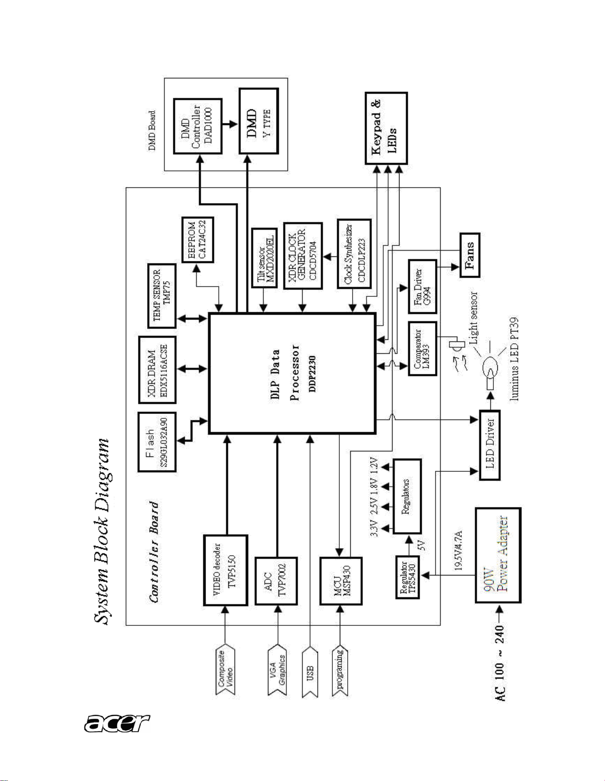
1.2 System Block Diagram
Page 11
K10
5
2 Firmware Upgraded Flow
This chapter provides the information regarding relevant equipments and upgrading procedure
for firmware upgrade.
Note:
Please check the firmware and composer version before any firmware upgrade procedures.
During firmware download period, please do not shut down PC or projector, this will cause flash
memory’s damage. And need to return the unit to manufacturer for flash memory recovery.
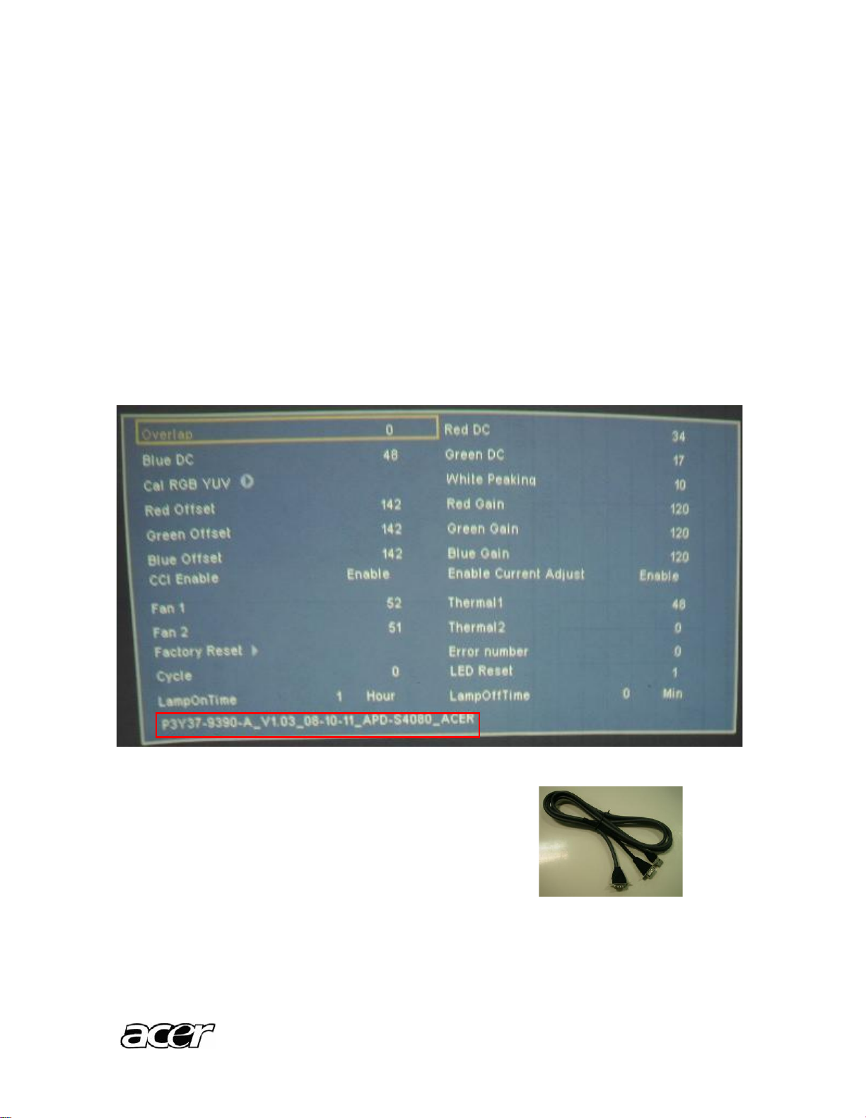
2.1 Check FW version
How to check the firmware version? Please press the button of Power, press “-“ twice, at
last press Menu. You will access the engineering mode and read the firmware version as
below.(This firmware version is just for reference.)
2.2 Setup Tool/Equipment
1. Computer
2. USB Burning Cable (See the picture)
3. Power Cord and AC Adaptor
2.3 Upgrading Procedure
Installing [DLP Composer (TM) Lite]
1. Double-click [DLP Composer Lite v7.1 Setup.exe].
Page 12
K10
6
2. Installation starts. Click [Next] to continue the installa tion process.
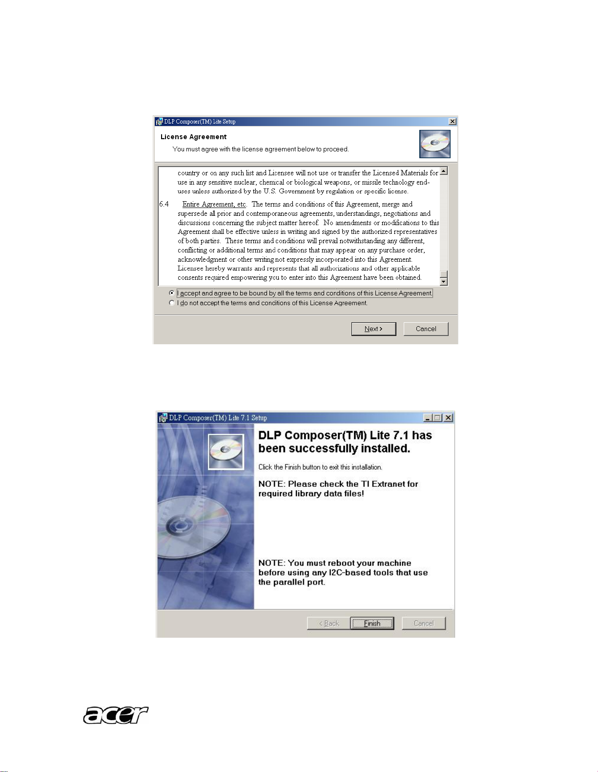
3. On the [License Agreement] screen, move the scroll bar on the right to the bottom,
select [I accept and agree to be bound by all the term s and conditions of this
License Agreement], and click Next to continue the installa tion process.
4. On the Select [Installation Type] screen, select [ALL] and click [Next] to continue the
installation process.
5. When the installation is finished, click [Finish] and reboot the PC. (A shortcut to DLP
Composer(TM) Lite is created on the desktop.)
Page 13

K10
7
USB Support - Installation (All Platforms)
This release includes support for a USB communications interface to DDP2000-based
projectors. The setup program includes the files needed to install USB support (for
Windows 98/Me/2000/XP only ---Win95 and WinNT are not supported). After DLP
Composer™ Lite is installed, to install the USB support, choose the "Install DDP2000 USB
Driver" icon under "DLP Composer™ Lite" in your Start menu.
Follow the instruction on the screen to press any key and wait for the installation done.
And copy the file “FlashDeviceParameters.txt” into the C: \ Program Files\ DLP Composer
Lite X.X
Operating procedure
1. Connect the Projector and PC via USB cable.
2. Double-click [DLP Composer (TM) Lite]. The following screen will appear.
Page 14

K10
8
3. Select [Edit]/[Preferences]/[Communications] to check USB in [Projector Interface].
4. Click [USB Device Identification].
5. Set the items on the [Vendor 0x451, Product 0x2000 ].
6. Click [OK].
7. Move the cursor to [Flash Loader] on the Project window of [DLP Composer Lite]. (The
[Flash Loader] screen will appear.)
8. Click [Browse] and select where the firmware [xxxxxxxxx.img] is for download.
9. Make sure [Skip Boot Loader Area] is with a check.
10. Press Menu and Power buttons cons tantly within ten seconds after insert the USB Burning
Cable and power Cord. Power LED will start flashing. That indicates the projector is in the
download mode. At this moment, you can release these two buttons.
11. Click [Start Download]. When the dialog box is di splayed, click [Yes].
Put checkmark next to
[Skip Boot Loader
Area],VALUE SETTING
32KB.
Click [Browse] and
select [*.img]
Click [Start Download]
Page 15

K10
9
12. Wait for the Completion of Burning and then remove Power Co rd and Burning Cable.
Click [Yes(是)]
Page 16

K10
10
3 Machine Disassembly and Replacement
3.1 Tools
Item
Photo
Long Nose Nipper
Nipper
Screw Bit(+):2*5*40
Screw Bit(+):2*4*60
Anti-static wrist strap
Anti-static wrist gloves
3.2 Disassembly Procedure
Warning
Put on the Static Electricity Ring when starting for repair.
Repair Environment suggest in Clean-room class 10000. Do not remove Optical
Engine or DMD panel outside the clean room.
While screwing or unscrewing screws, please keep the screwdriver straight.
Keeping screwdriver inclined will damage the screw holes.
Please turn off the power before replacing any parts.
Page 17

K10
11
Step
Figure
Description
1
1. Press the power button
to shutdown the projector
and disconnect the power
cord.
2. Flip the projector and
remove the lens cover.
2
1.
2.
1. Loosen screws
J82035-2510-00*2 as
shown.
2. Loosen the screws
J1635-3673-00*4.
3
Raise the top cover
gently and disconnect the
keypad FFC between the
top cover and mainboard.
J82035-2510-00*2
J1635-3673-00*4
Page 18

K10
12
4
Loosen the four screws
J1635-2901-00*4
to remove the keypad .
5
Remove the Lens Cover
and Lens Ring gently.
6
Loosen the four screws
J1635-A074-00*4 for
moving Bottom Cover.
7
P.1
1. Unplug the LED Drive
Board from Main Board.
2. Remove all LED Wires.
J1635-2901-00*4
Lens Ring
Lens Cover
J1635-A074-00*4
Page 19

K10
13
P.2
8
Loosen the two screws
J1635-A074-00*2 on
LED Drive Board to
remove the Drive Board
Heat sink.
9
1. Unplug Photo Sensor
Wire and Fan Wire
from the Main Board.
2. Loosen the three
screws
J1635-A074-00*3.
3. Remove Main Board.
J1635-A074-00*3
J1635-A074-00*2
Photo Sensor Wire
Fan Wire
Page 20

K10
14
10
1. Loosen the screw
J1635-3172-00 to
remove the Photo
Sensor Board.
2. Unplug the three LED
Wires.
11
Loosen screws
J1635-2021-00*4 for
raising the DMD Board
and DMD Heat sink.
12
Loosen the two screws
J1635-2290-00*2 to
remove the Focus-ring.
J1635-3172-00
LED Wires
Long
Short
J1635-2021-00*4
J1635-2290-00*2
Page 21

K10
15
13
Loosen the four screws
J1635-2250-00*4 to
remove the Lens.
14
Loosen the three screws
J1635-2021-00*3 to
remove the DC Fan.
15
Loosen the screws
J1635-2021-00*4 and
J1635-2250-00*2 to
remove the heat sink.
Note
Note:
When assembling the
heat sink, please take the
LED Thermal Pad
protection film off firstly.
J1635-2250-00*4
RGB
J1635-2021-00*4
Thermal Pad protection film
J1635-2021-00*3
Page 22

K10
16
3.3 Mechanical Drawing
1. Top Cover
2. Lens Ring
3. Lens Cover
4. DMD Heatsink
5. DMD Board
6. Optical Engine
7. LED Heatsink
8. LED Drive Board
9. Drive_Board Heatsink
10. Main Board
11. Bottom Cover
12. Foot Screw
Page 23

K10
17
4 Troubleshooting and Verifying the Repair
This chapter provides technicians and people who have an electronic backg round a
primary description about maintaining the product. Moreover, you can get the
appropriate operation to solve some complicated problems of component repairing and
professional problems.
4.1 Troubleshooting
Warning:
Do not directly look into the lens to avo id eyesight damages.
The projector is equipped with ventilation holes (intake) and ventilation holes (exhaust). Do
not block or place anything near these slots. Or internal heat build-up may cause picture
degradation or damaging the projector.
Confirm Software and hardware
(1) Confirm FW version (refer to Engineering Mode) .
(2) Confirm LED indicator.
(3) Confirm cable connec tion well.
Page 24

K10
18
Power Source Troubleshooting
OK
NG
OKNGOK
NG
No P o w er
Source after
tu rning on
Check AC
socket and
connector
Check LED
and keypad
FPC
Check
Mainboard
and power
cable
Replace
Mainboard
Replace AC
socket
Replace
keypad PFC
Replace
power cable
Page 25

K10
19
Fan Failure Troubleshooting
NGNGOKOKNG
Fan failure
after turning
on
Check Fan
connection
Check Fan
Check
Mainboard
Reconnect
fan
Replace fan
Replace
Mainboard
Page 26

K10
20
Video Signal and VGA Signal Troubleshooting
NGOKNGOKNG
Video No
Signal
Check
Source
Turn on
source
Check
Cable
Replace
Cable
Check
Main BOard
Replace
Main Board
NGOKNGOKNG
Computer
No Signal
Check
Source
Check
Cable
Check
Main Board
Turn on
source
Replace
Cable
Replace
Main Board
Page 27

K10
21
NGOKNGOKNG
Image
abnormal
Power on
again and
reset OSD
OK
Check input
cable and
signal setting
Check
Mainboard
Check
Optical
engine
Adjust Input
Signal
Replace
Mainboard
Replace
Optical
engine
NGNGOKOKNG
Color
abnormal
Check input
cable
and
signal setting
Check
Mainboard
Check
Optical
engine
Adjust Input
Signal
Replace
Mainboard
Replace
Optical
engine
Page 28

K10
22
Operation Function Troubleshooting
NG
NG
Button Failure
Check
Keypad and
FFC
OK
Check
Mainboard
Replace
Keypad and
FFC
Replace
Mainboard
Page 29

K10
23
4.2
Verifying the Repair
After repairing projector (Dissembling and assembling projector), Repair center should
verify the quality of repaired unit. Here is a general guide for all repaired model. That means
if the projector is without S-Video port, repair center can skip the portion of S-Video
verification.
(1) Signal test (Each I/O can function normally)
Connect all connector to the jacks one a fter the other to check whether each channel can
project normally.
I/O port
Monitor In (VGA)
Test Equipment
Standard Pattern generator (Ex. Quantum data)
Signal format
800*600 60Hz
I/O port
Video
Test Equipment
Standard Pattern generator (Ex. Quantum da ta) or DVD player
Signal format
NTSC
I/O port
S-Video
Test Equipment
Standard Pattern generator or DVD player
Signal format
480i
I/O port
Audio input
Test Equipment
Connect audio input to audio output of DVD player
Signal format
480i
(2) Operation test
Buttons operation
Button description
Test criteria
Power button
1. Mechanical motion (Up & Down) should be free from getting stuck
when pressing the Power button.
2. Press “power” button and projector will switch on.
Menu
1. Mechanical motion (Up & Down) should be free from getting stuck
when pressing the Menu button.
2. Press Menu button can make projector function normally.
4-way button
(Keystone/Auto/Source)
1. Mechanical motion (Up & Down) should be free from getting stuck
when pressing the 4-way button.
2. Press 4-way button can make projector function normally.
Focus ring
Ring
Test criteria
Focus ring
The feeling of rotating Focus ring to the end of right and le ft by hand
should free from seizing.
Page 30

K10
24
(3) Image Quality
Projected image size: 25 inches (diagonal length).
Zoom ring: Adjust zoom ring to wide (Maximum projection size).
VGA
I/O port
Monitor In (VGA)
Test Equipment
Standard Pattern generator (Ex. Quantum da ta)
Signal format
800*600 60Hz
Projected image size
25” in diagonal length
Test Pattern
Test criteria
ANSI Brightness
Apparent color strip, bend and streak
corner on the projected image are not
allowable.
Extreme Gray-Scale
--0 represents full black, 255
represents full white.
--Distinguishing the gray from black at
the value of 32 and the gray from
white at the value of 239 easily are
acceptable.
Page 31

K10
25
Circular Geometry, Cross hatch
and Dots
1. The four lines of outer frame
should not only be existent but
also distinguishable.
2. The dots in the square should be
distinguishable.
Scaled Text
1. Rotate Zoom ring to wide mode
(Maximum projected image)
2. Fix projector to set diagonal length
of projected image to 60”.
3. Adjust focus ring to make
resolution of 4 corners and center
are balanced.
4. Check the characters should be
recognized easily.
5. Rotate Zoom ring to tele mode
(Minimum projected image)
6. Adjust focus ring to make
resolution of 4 corners and center
are balanced.
7. Check the characters should be
recognized easily.
INFOCOMM SMPTE 133
1. The intervals of center thin white
and black bars should be distinct.
2. The squares around the small
circle in the center show the
transition of full white to full black.
Page 32

K10
26
Video
I/O port
Video
Test Equipment
Standard Pattern generator (Ex. Quantum data)&DVD player
Criteria
No apparent color deviation on the projected image
5
Connector Information
This section provides each connector location on boards and function of each board.
They will be useful for your detecting the defective boards.
5.1 Main Board
Connector
Description
CN1
FFC Cable ( to keypad)
J1
DMD Board
J5
LED Drive Board
J9
Fan
J10
Photo sensor
J9
J 10
CN1
J 1
J5
Page 33

K10
27
5.2 LED Drive Board
Connector
Description
J2
LED-R
J3
LED-B
J4
LED-G
J4: G
J3: B
J2: R
Page 34

K10
28
Appendix A: Measurement method and Formula
Equipment : Chroma 7600 Video Pattern Generator values
Set projection diagram to wide size, 25 ” inches diagonal image
1. Bightness measurement
Measure the incident light at th e ANSI nine points of the screen with the illuminometer
placed in the plane of the focused image on normal white condition. Calculation is according
to ANSI standard (for 60” diagonal projection area case)
Test Pattern: Full White Test Pattern
Formula : Average( L1+L2+…+L9) (Projection Area)
= (L1+L2+…+L9)/9 0.508m x 0.381m
L1, L2, …., L9 : the lx reading of ANSI 9 points
ANSI Test point definition
2. Light uniformity measurement(JBMA)
Test Pattern: Full White Test Pattern
Formula :
JBMA uniformity = Average (L1,L3,L7,L9 )/L5
L1,L2,…,L9 : the lx reading of 9 ANSI points
3. Light Uniformity(Dark Corner)
Test Pattern: Full White Test Pattern
Formula:
Page 35

K10
29
%100))L9L8,L7,L6,L5,L4,3,L2,,1(geL11)/Avera(Min(L10,)_( LLcornerDarkUniformityLight
L1, L2,…,L9, L10, L11: the lx reading of 13 ANSI points
4. Contrast measurement(JBMA)
First measure the light output of nature white pattern of ANSI nine points. Second,
measure the dark pattern as the same way. And calculate the ratio of them.
Test Pattern: Full White and Full Dark Test Pattern
Formula:
Average(L1,L2,L3,L4,L5,L6,L7,L8,L9) of NW : Average(L1,L2,L3,L4,L5,L6,L7,L8,L9) of
Dark
= NW(L1+L2+L3+L4+L5+L6+L7+L8+L9)/9 : Dark(L1+L2+L3+L4+L5+L6+L7+L8+L9)/9
5. TV DISTORTION
Unit: %
Brightness: Default
Contrast: Default
Measurement procedure (Projection Size 30 inch):
Measure the dimensions H1, H2 and H3, with H3 at the half image width, as shown above
for both zoom settings. For each the distortion is defined as:
VERTICAL
%100*1
3
1
H
H
distTV
%100*1
3
2
H
H
distTV
Measure the dimensions W1, W2 and W 3 at the half image height, as shown above. The
distortion is defined as:
HORIZONTAL
%100*1
3
1
W
W
distTV
%100*1
3
2
W
W
distTV
All should be within the absolute specification tolerance.
Page 36

K10
30
Appendix B: Computer Compatibility
Mode
Resolution
Vertical Frequency (Hz)
Horizontal Frequency
(kHz)
59.940 Hz
31.469 kHz
72.809 Hz
37.861 kHz
75.000 Hz
37.500 kHz
VGA
640 x 480
85.008 Hz
43.269 kHz
56.250 Hz
35.156 kHz
60.317 Hz
37.879 kHz
72.188 Hz
48.077 kHz
75.000 Hz
46.875 kHz
SVGA
800 x 600
85.061 Hz
53.674 kHz
60.004 Hz
48.363 kHz
70.069 Hz
56.476 kHz
75.029 Hz
60.023 kHz
XGA
1024 x 768
84.997 Hz
68.677 kHz
75.000 Hz
67.500 kHz
1152 x 864
60.000 Hz
60.000 kHz
1280 x 960
1280 x 1024
60.020 Hz
63.981 kHz
84.88 Hz
71.55 kHz
74.88 Hz
62.75 kHz
SXGA
1280 x 800
59.8 Hz
49.7 kHz
Appendix C: Video Compatibility
NTSC-M, NTSC-4.43
.PAL-M,N,B,D,G,H,I
.SECAM
Signal
Horizontal Frequency (kHz)
Vertical Frequency (Hz)
480i
15.8 kHz
60 Hz
480p
31.5 kHz
60 Hz
576i
15.6 kHz
50 Hz
576p
31.3 kHz
50 Hz
720p
45.0 kHz
60 Hz
720p
37.5 kHz
50 Hz
1080i
33.8 kHz
60 Hz
1080i
28.1 kHz
50 Hz
Page 37

K10
31
Appendix D: Spare Parts list
Introduct ion
This section is a list of all the FRU removal. Following the FRU table of contents is an
enlarged view of the entire projector, which shows the primary FRUs in the projector.
When working on the projector, use appropriate anti -static precautions such as anti -static
mats, wrist straps and grounded work surfaces.
Failure to do this can de stroy static-sensitive components and make the product
inoperable.
CATEGORY
DESCRIPTION
FOXCONN
PART NO.
Remark
BOARD
KEYPAD_DIP_PCB_ASY_APD -S4080_ROHS(without metal dome)
P3Y47-7100
BOARD
PHOTO SENSOR_DIP_PCB_ASY_DPD -S290_ROHS
P3K47-5100
BOARD
MAIN_DIP_PCB_ASY_SPARE PARTS_APD -S4080_ROHS
P3Y84-7100
BOARD
DRIVE_DIP_PCB_ASY_SPARE PARTS_APD -S4080_ROHS
P3Y84-7400
BOARD
DMDBOARD_DIP_PCB_ASY_SPARE PARTS_APD -S4080_ROHS
P3Y84-7500
CABLE
VGA-VGA+USB CABLE_P4883-08_PAN_ROHS
J2552-0227-00
CABLE
WIRE CON-CON_PR-P0008B_YUAN YUH_4PIN_L72MM_10064#34_ROHS
J2595-0335-00
CABLE
WIRE CON-CON_PR-W0005D_YUAN YUH_6PIN_L45MM_1061#24_ROHS
J2595-0334-00
CABLE
WIRE CON-CON_PR-W0001D_YUAN YUH_6PIN_L62MM_1061#24_ROHS
J2595-0333-00
CABLE
FFC CABLE_A24100C3344 NB_ENTERY_0.5PITCH_24PIN_L100MM_ROHS
J2591-0110-00
CASE/COVER/BRACKET
ASSEMBLY
TOP COVER SPARE PART_APD -S4080_ROHS
P3Y84-4500
CASE/COVER/BRACKET
ASSEMBLY
BOTTOM-COVER SPARE PART_APD -S4080_ROHS
P3Y84-4510
Note: FW Upgrade cable
Acer PN: 50.J860F.003
Page 38

K10
32
CASE/COVER/BRACKET
ASSEMBLY
LOGO PLATE_APD -S4080_ROHS
P3Y38-1500-00
CASE/COVER/BRACKET
ASSEMBLY
I/O NAME PLATE_APD -S4080_ROHS
P3Y38-1530-00
CASE/COVER/BRACKET
ASSEMBLY
LENS-COVER_APD -S4080_00_NO PAINTING_ROHS
P3Y34-4610-00
CASE/COVER/BRACKET
ASSEMBLY
LENS RING_APD -S4080_00_FOR PAINTING_ROHS
P3Y34-4550-99
CASE/COVER/BRACKET
ASSEMBLY
FOCUS RING_APD -S4080_00_FOR PAINTING_ROHS
P3Y34-4520-99
CASE/COVER/BRACKET
ASSEMBLY
DMD HEATSINK_APD -S4080_00_NO PAINTING_ROHS
P3Y35-6010-00
CASE/COVER/BRACKET
ASSEMBLY
DRIVER_BOARD HEATSINK_APD -S4080_00_NO PAINTING_ROHS
P3Y35-6011-00
CASE/COVER/BRACKET
ASSEMBLY
LED COOLER MODULE_APD -S4080_DEFAULT_NO PAINTING_ROHS
P3Y35-0550-00
DIGITAL LIGHT DEVICE
OPTICAL ENGINE ASY(WITH DMD BOARD)SPARE
PARTS_APD-S4080_ROHS
P3Y84-2200
DIGITAL LIGHT DEVICE
DMD-0.45INCH -SVGA Y-TYPE_DPD-S290_ROHS
P3K36-7010-00
FAN
DC FAN_AFB0412HHA -A(R00)(L=70MM)_DELTA_ROHS
J2394-0114-00
FAN
DC FAN_BUB0412VHD -8J12(R00)(L=35MM)_DELTA_ROHS
J2394-0115-00
MISCELLANEOUS
IO-HOLDER_APD -S4080_00_NO PAINTING_ ROHS
P0N35-0590-00
MISCELLANEOUS
ESD MYLAR_APD -S4080_ROHS
P3Y38-1570-00
MISCELLANEOUS
LED PAD_APD-S4080_ROHS
P3Y38-1180-00
MISCELLANEOUS
DMD APERTURE_DPD -S290_00_NO PAINTING_ROHS
P3K35-0010-00
SCREW
HEXAGON-HEAT-BOLT-4.8_3M_ROHS
82035-2510-00
Page 39

K10
33
SCREW
SCREW_TP_2.6_7_A_1.6_D=4.3_NI_NONE_ROHS
J1635-3673-00
SCREW
SCREW-WASHER._TP_2_5_D_1_D=3.2_SUS_NONE_SUS_ROHS
J1635-2901-00
SCREW
SCREW_M_2.5_7_A_2_D=4.5_NI_NONE_ROHS
J1635-A074-00
SCREW
SCREW-WASHER_M_2_4_A_1.3_D=3.5_BLACK_NONE_PB P_ROHS
J1635-3172-00
SCREW
SCREW_M_2_5_A_D=3_A0.8_BLACK_HEAT -TREATMENT_ROHS
J1635-2250-00
SCREW
SCREW._TP_2_2.3_A_1_D=3_BLACK_NONE_ROHS
J1635-2290-00
SCREW
SCREW._M_2_6_A_1.3_D=3.2_NI_HEAT -TREATMENT_ROHS
J1635-2021-00
SCREW
FRONT FOOT_APD -S4080_00_NO PAINTING_ROHS
P3Y34-4540-00
 Loading...