

Page 1
1 Introduction
This installa tion guide describes the features of the IDUR housing and tells
you how to install t he basic system com ponents such as disk dri ves, syst em
board, or expansion boards. Descriptive illustrations accompany the
installat i on pr ocedures.
If you receive a complete system, the basic
components are already installed.
2 Positioning the System Housing
2.1 Standalone System
For a standalone system, rotat e the legs outward to stabilize the housing.
IDUN Housing
1
Page 2
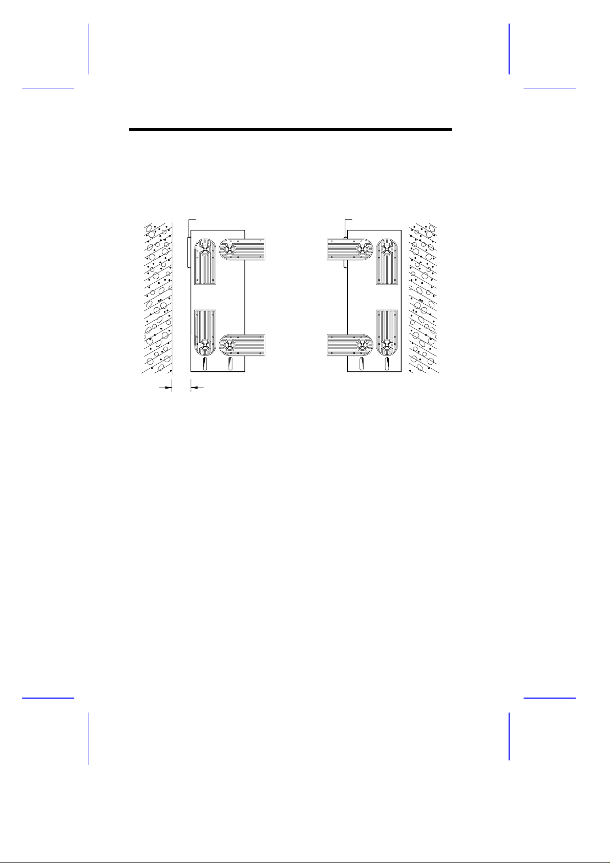
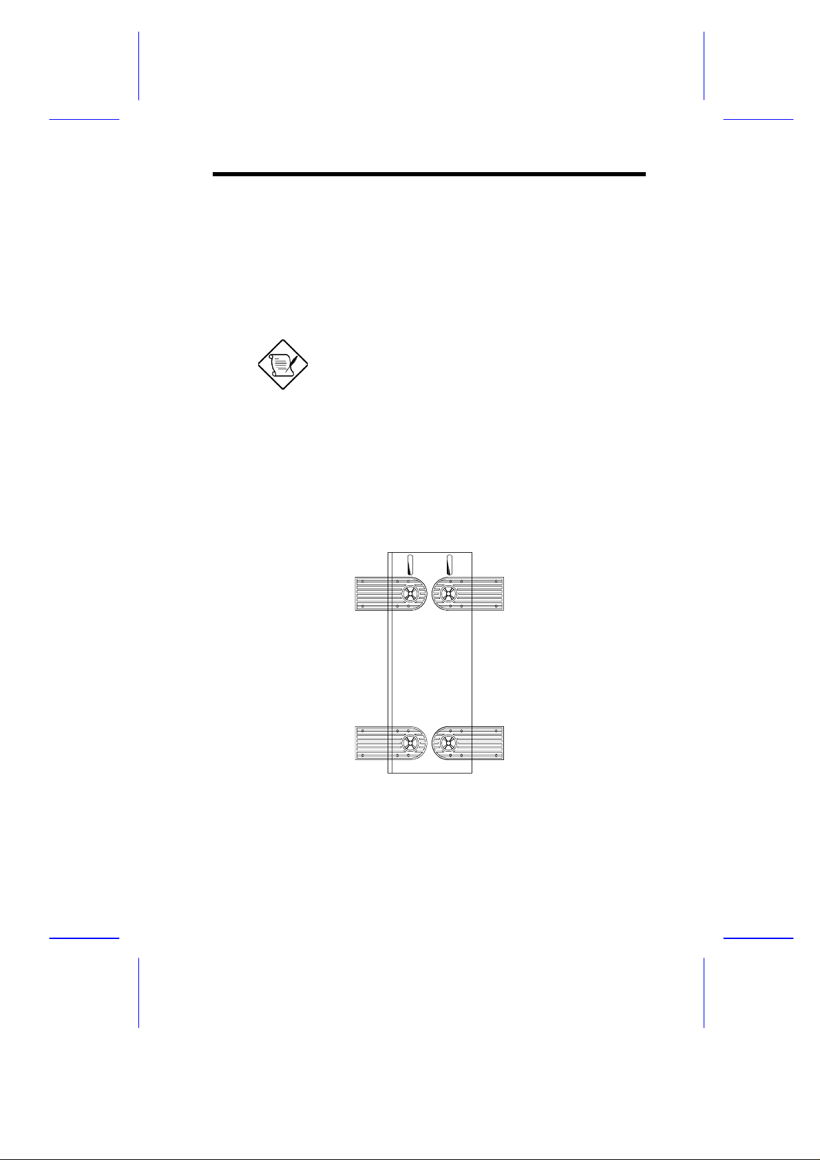
2.2 Against a Wall
Figure A
Fans
5~10 cm
Figure B
Fans
Fans Facing a Wall
When standing the housing with the fans facing a wall, leave a space of
5~10 cm from the wall to al low air circulation, t hen position the legs as i n
Figure A.
Fans Facing Out
When standing the housing with the fans facing out, you can put the system
close to the wall and position the legs as in Figure B.
2
Installation Guide
Page 3
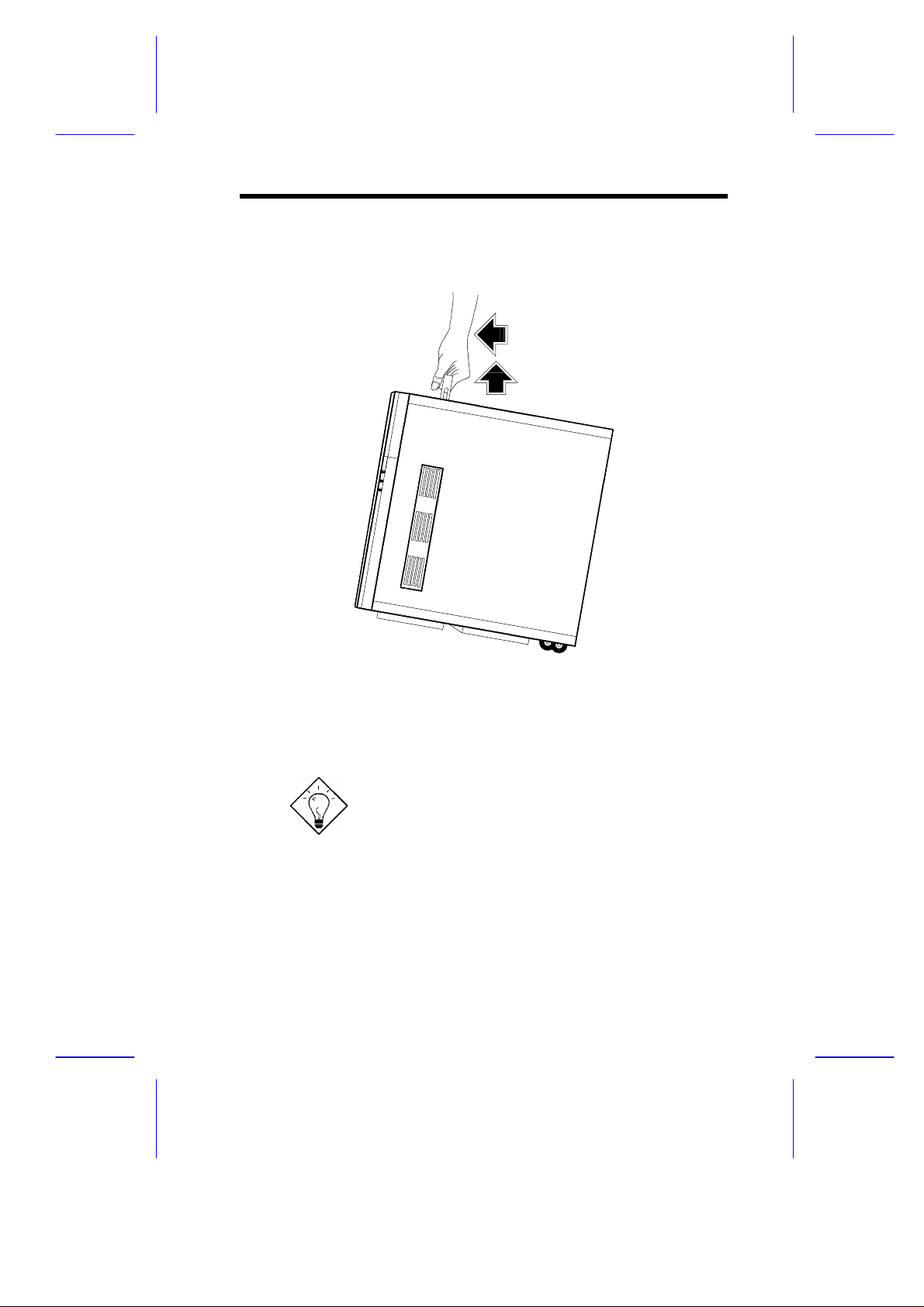
3 Transporting the System
The housing has a handle on top and two wheels behind the feet to facilitate
moving to shor t di stances.
Rotate the feet inward befor e moving the housing.
When transport ing the housing, pull out the handle, at the same ti me lif ting
the unit front a few inches from the floor. Slide the housing for ward with the
wheels supporting the rear.
IDUN Housing
3
Page 4
4 Features
k
D
D
y
e
s
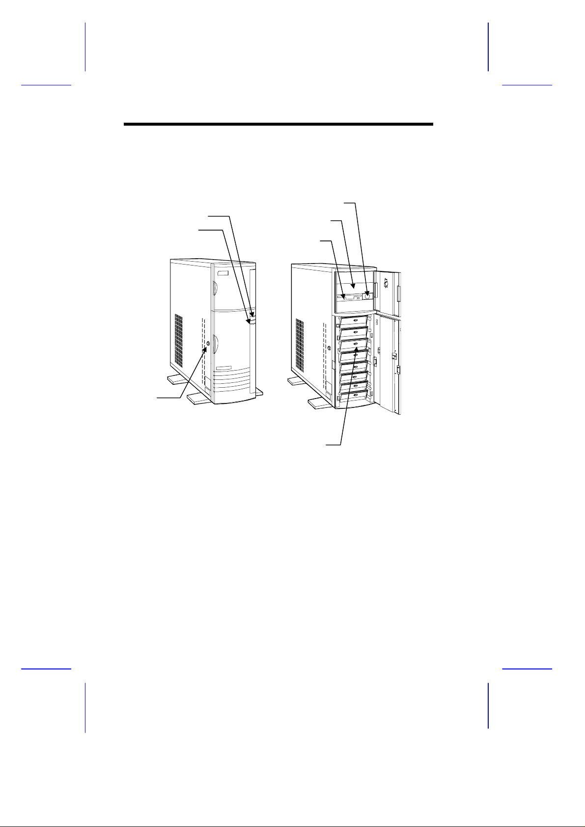
4.1 Front Panel
Power LE
Hard Disk Drive LE
Keyloc
Power Switch
5.25-inch Drive Ba
3.5-inch Driv
SCSI Hard Disk Drive Tray
4
Installation Guide
Page 5
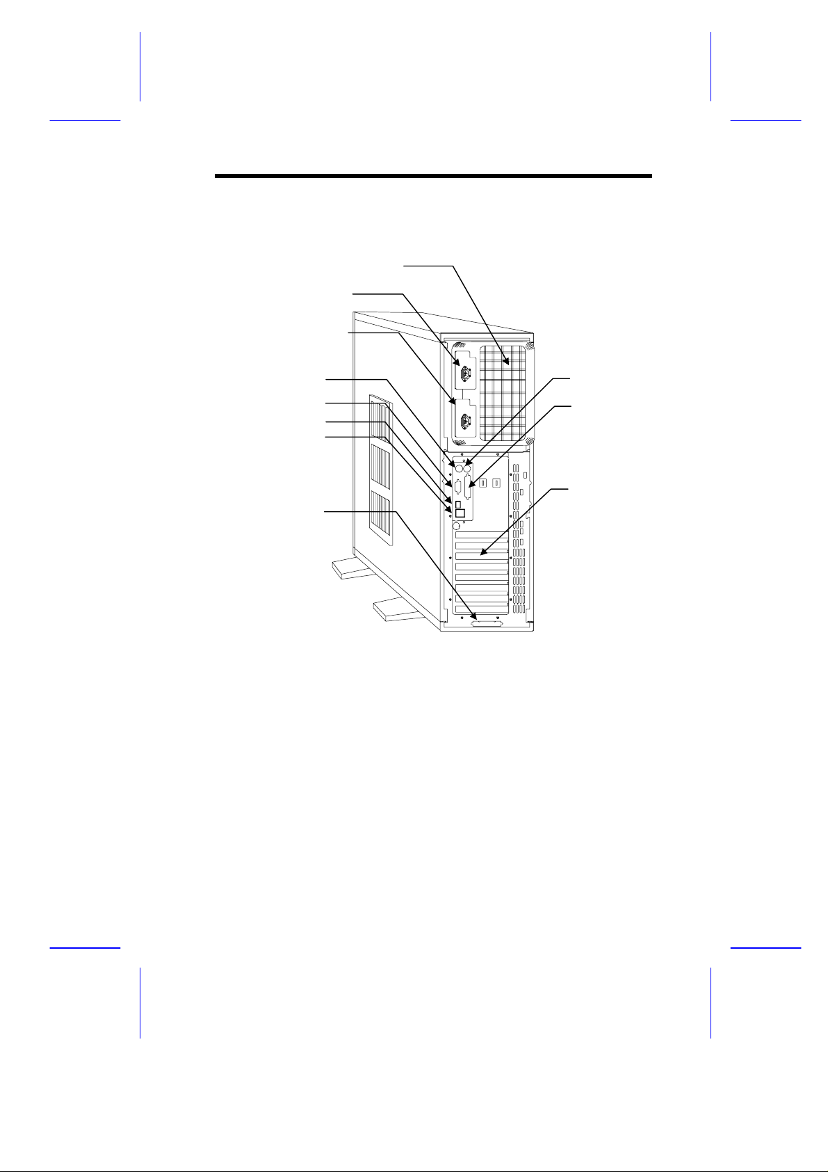
4.2 Rear Panel
s
t
t
r
t
r
2
Power Supply Bay
Power Socket 1
Power Socket
Keyboard Por
Video Por
RJ-45 Connecto
USB Connecto
SCSI Expansion Slo
Mouse Port
Parallel Port
Expansion Slots
IDUN Housing
5
Page 6
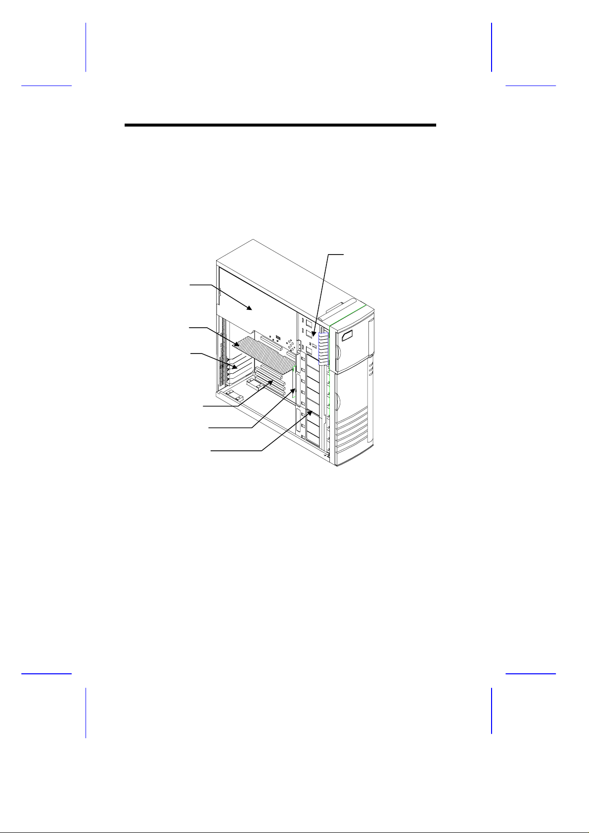
4.3 Internal Structure
d
d
d
The following figure shows the housing internal structure and some of the
basic system com ponents.
3.5-inch and 5.25-inch
Power Supply
Metal Plate
(covering two
redundant
power supply
modules)
CPU Boar
Expansion Slot
Brackets
System Boar
Backplane Boar
Drive Bays
SCSI Drive Tra ys
6
Installation Guide
Page 7
5 Opening the Housing Panels
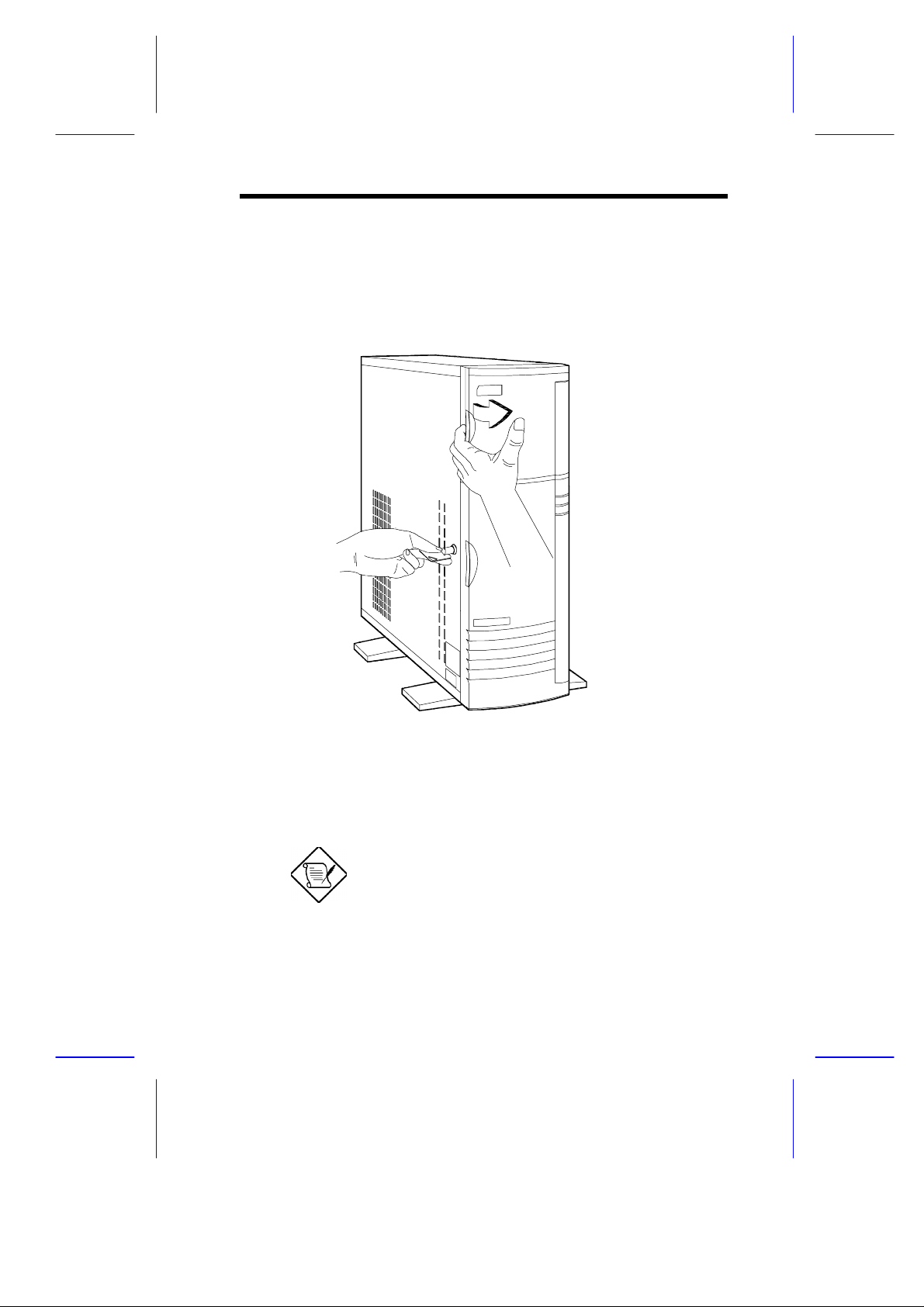
5.1 Upper Front Panel
Hold the left edge of the upper front panel to open it and gai n access to the
diskette drive bays.
The housing keys are inside the front panel.
IDUN Housing
7
Page 8
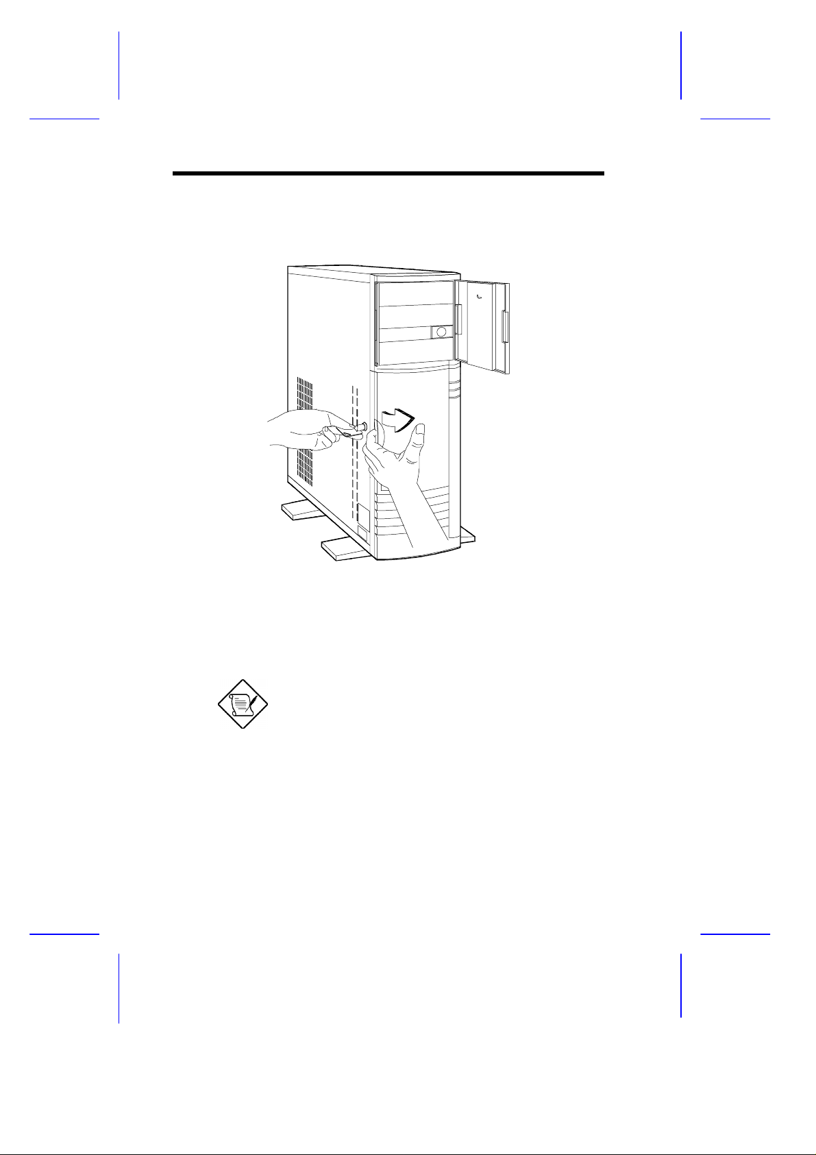
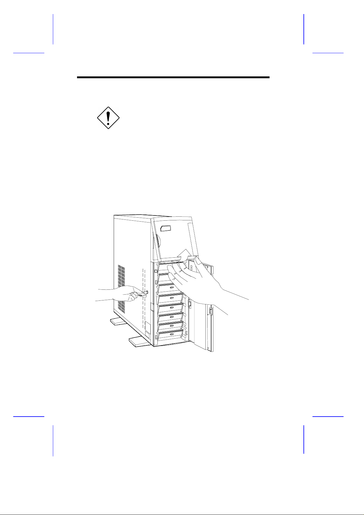
5.2 Lower Front Panel
Unlock the housing with the key. Pull the lower panel to access the drive
trays.
You cannot remove the key after you have
unlocked the housing. You can remove it only
when you lock the housing again.
8
Installation Guide
Page 9
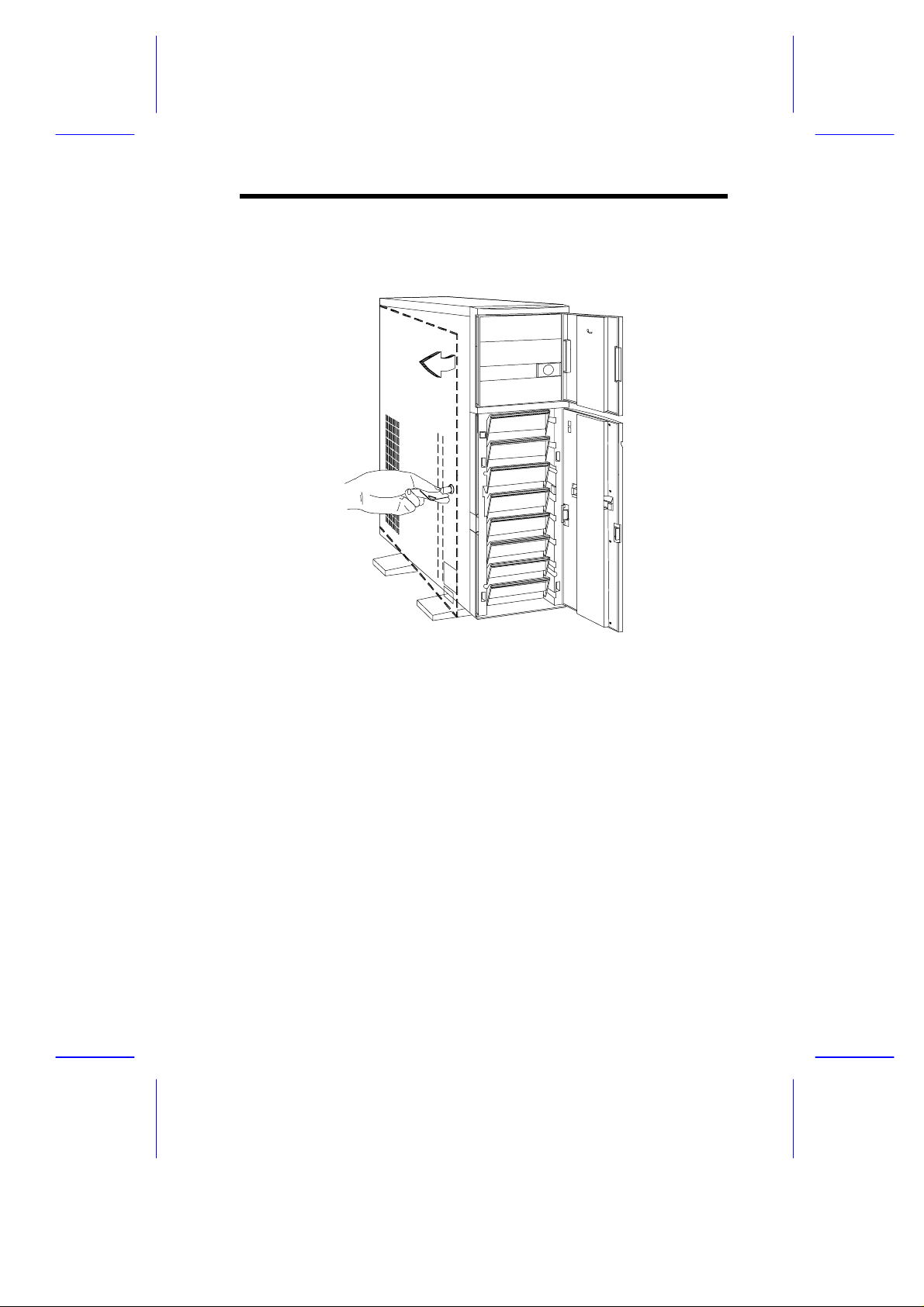
5.3 Left Panel
Pull on the key to swing the left panel open. If necessary, you may use a
screwdriver to pry open the panel.
IDUN Housing
9
Page 10
6 Installing Disk Drives
Turn off the power switch and unplug the power
cord before installing or removing diskette drives.
6.1 3.5-inch Drive
1. Open the lower front panel.
2. Remove the upper panel including its frame by pressing the latch
underside and pulling the panel out.
10
Installation Guide
Page 11

3. Remove the screw attaching the 3.5-inch drive frame to the housing.
4. Secure a 3.5-inch drive on the frame with four screws.
5. Insert the drive into the drive bay and secure it with a screw.
6. Connect the diskette drive cables.
IDUN Housing
11
Page 12

6.2 5.25-inch Drive
You may install a CD-ROM, digital audio tape (DAT), hard disk, diskette
drive or any other 5.25-inch device into the drive bay.
1. Open the lower front panel.
2. Remove the upper panel including its frame by pressing the latch
underside and pulling the panel out.
3. Secure the drive guides on the sides of a 5.25-inch drive.
4. Insert the drive into the drive bay.
5. Connect the signal and power cables to the drive.
12
Installation Guide
Page 13

6.3 Hard Disk
1. Pull out a dri ve tray.
2. Place a hard disk on the tray and secure it with four screws.
IDUN Housing
13
Page 14

3. Insert the tray back into the housing. Make sure to push back the drive
tray handle in place before pushing the tray in completely. The tray
does not fit in if t he handle is not in place.
4. Connect the hard disk cables.
If you installed a SCSI backplane board into the
housing, see the backplane board manual for
hard disk installation instructions.
14
Installation Guide
Page 15

7 Upgrading to Two Redundant
Power Supply Modules
Follow the instructions in this section when you want to upgrade to two
420W redundant power supply modules.
To reduce the risk of electric shock, make sure to
disconnect all power supply cables from the wall
socket before opening the system housing.
7.1 Removing the Existing Power Supply
1. Unplug the AC power cable from the wall socket, then remove the
plastic fan cover on the rear panel.
2. Open and remove the lower front and left doors. See section 5.
3. Remove the three screws that secure the right door.
DO NOT open the RIGHT door at this moment!
Doing so will damage the power sharing board
and cables attached to its inner side.
4. Unplug the connectors
- from t he power supply to the power sharing board
- from the power sharing board to the system board
- from t he power sharing board t o t he disk drives
- from the fans to the system board
Remember where you unplugged each connector. You will have to
reconnect them later.
IDUN Housing
15
Page 16

5. When fini shed disconnecting all the cables attached to the inner side of
the right door, open and remove the right door.
Be careful when opening and removing the right
door to avoid damaging the power sharing board
attached to its inner side.
6. Remove the screws that secure the power supply holding plate.
16
Installation Guide
Page 17

7. Slide the holding plate to the right f or about an inch.
8. Pull out the lower part of t he holding plate and unhook the upper part
from t he housing roof .
You may need to pull the plate downward to
re mov e it easier.
IDUN Housing
17
Page 18

9. Remove the screws that secure the metal cover of the upper power
supply bay to the rear panel.
10. Remove the screws that secure the power supply module. In the
process, make sure to support the module with your hand.
18
Installation Guide
Page 19

7.2 Installing the Power Supply Modules
1. After you have removed all the screws that secure the existing power
supply module to the lower bay, carefully move the module to the upper
power supply bay.
2. When in place, secure the first power supply with screws.
3. Get the second redundant power supply ready.
4. Firmly hold the power supply and align it t o the lower bay.
5. When in place, secure the second power supply with screws.
6. Reinstall the right door but do not cl ose it completely.
IDUN Housing
19
Page 20

7. Connect all the power supply cables to the connectors on the power
r
d
sharing board. Make sure to connect the connectors of power suppl y 1
to the three upper connectors on the power sharing board. Connect the
connectors of power supply 2 to the three lower connectors on the
power sharing board.
The power connectors are foolproof and connect
only in one direction. If a connector does not fit in
completely, reverse its orientation then try to
reconnect.
Cable connections fo
power supply 1
Power sharing boar
Cable connections for
power supply 2
8. Arrange all the cables from the power sharing board and fans to
facilitate connection to the system board and disk drives. Do not let
power cables block the housing exhaust and fans.
9. Close the right door completely and secure it with the screws that you
removed earlier.
10. Reconnect the fan connectors.
11. Reconnect the system board power connectors.
20
Installation Guide
Page 21

12. Reconnect the disk drives power connectors.
13. Reinstall the holding plate by inserting the upper part to the rail on t he
inner side of the housing roof, then fitting in the lower part.
14. Slide the holding plate to the left unti l it fits com pletely and the screw
holes match.
15. Secure the holding plate with the screws that you removed earlier.
16. Reinstall the left door and close it.
17. Close the lower front door and lock the system housing.
18. Reinstall the plastic fan cover on the rear panel.
19. Reconnect the AC power cables.
IDUN Housing
21
Page 22

8 Installing a System Board
The housing accommodat es various syst em boar d sizes. You can rearrange
the pegs on the system board plat e to fit the board that you wish to inst all.
1. If you have not done so, open the housing following the steps in
section 4.
2. When ready, align the system boar d holes to the pegs with the external
ports facing t he rear of the housing.
3. Secure the board with eight screws.
22
Installation Guide
Page 23

9 Installing an Expansion Board
1. Remove an expansion slot bracket cover. Save the screw to secure the
expansion board.
IDUN Housing
23
Page 24

2. Align an expansion board with the open slot and insert the golden
fingers into the expansion bus connector.
3. Secure the board with a screw.
24
Installation Guide
Page 25

10 Installing a CPU Board
If your system board does not incl ude a CPU socket, fol low these steps to
install a CPU board.
1. Locate the CPU board connector in the system board.
2. Insert the board into the connector.
Make sure that the boar d is pr oper ly seated in the
connector.
3. Secure the board with a screw.
IDUN Housing
25
Page 26

4. Align the plastic suppor t bar wi th the board edge.
5. Insert the right end of the plastic bar to the hole on the side of the
backplane board and the left end to the hole on the rear panel.
Left End
Right End
26
Installation Guide
Page 27

6. Insert the left end of the metal support bar tabs to t he holes on the r ear
panel and align the right end to the screw holes on the side of the
backplane board.
7. Secure the metal bar with two screws.
IDUN Housing
27
Page 28

11 Connecting External Devices
11.1 Connecting a Monitor
28
Installation Guide
Page 29

11.2 Connecting a Keyboard
IDUN Housing
29
Page 30

11.3 Connecting a Mouse
30
Installation Guide
Page 31

11.4 Connecting a Printer
IDUN Housing
31
Page 32

12 Complete System Connections
32
Installation Guide
 Loading...