


 Loading...
Acer Ferrari 3400 Series
Service Guide
Service guide files and updates are available on the ACER/CSD web; for more information, please refer to http://csd.acer.com.tw

Revision History
Please refer to the table below for the updates made on Ferrari 3400 service guide.
Date |
Chapter |
Updates |
|
|
|
|
|
|
|
|
|
|
|
|
|
|
|
|
|
|
|
|
|
II
justmanuals.com

Conventions
The following conventions are used in this manual:
SCREEN MESSAGES |
Denotes actual messages that appear |
|
on screen. |
|
|
NOTE |
Gives bits and pieces of additional |
|
information related to the current |
|
topic. |
|
|
WARNING |
Alerts you to any damage that might |
|
result from doing or not doing specific |
|
actions. |
|
|
CAUTION |
Gives precautionary measures to |
|
avoid possible hardware or software |
|
problems. |
|
|
IMPORTANT |
Reminds you to do specific actions |
|
relevant to the accomplishment of |
|
procedures. |
|
|
IV

Preface
Before using this information and the product it supports, please read the following general information.
1.This Service Guide provides you with all technical information relating to the BASIC CONFIGURATION decided for Acer's "global" product offering. To better fit local market requirements and enhance product competitiveness, your regional office MAY have decided to extend the functionality of a machine (e.g. add-on card, modem, or extra memory capability). These LOCALIZED FEATURES will NOT be covered in this generic service guide. In such cases, please contact your regional offices or the responsible personnel/channel to provide you with further technical details.
2.Please note WHEN ORDERING FRU PARTS, that you should check the most up-to-date information available on your regional web or channel. If, for whatever reason, a part number change is made, it will not be noted in the printed Service Guide. For ACER-AUTHORIZED SERVICE PROVIDERS, your Acer office may have a DIFFERENT part number code to those given in the FRU list of this printed Service Guide. You MUST use the list provided by your regional Acer office to order FRU parts for repair and service of customer machines.
V
justmanuals.com

VI

Table of Contents
Chapter 1 System Specifications |
1 |
Features . . . . . . . . . . . . . . . . . . . . . . . . . . . . . . . . . . . . . . . . . . . . . . . . . . . . . . . . . . . .1
System Block Diagram . . . . . . . . . . . . . . . . . . . . . . . . . . . . . . . . . . . . . . . . . . . . . . . . .3
Board Layout . . . . . . . . . . . . . . . . . . . . . . . . . . . . . . . . . . . . . . . . . . . . . . . . . . . . . . . .4
Top View . . . . . . . . . . . . . . . . . . . . . . . . . . . . . . . . . . . . . . . . . . . . . . . . . . . . . . . .4
Bottom View . . . . . . . . . . . . . . . . . . . . . . . . . . . . . . . . . . . . . . . . . . . . . . . . . . . . .5
Outlook View . . . . . . . . . . . . . . . . . . . . . . . . . . . . . . . . . . . . . . . . . . . . . . . . . . . . . . . . .6
Front Open View . . . . . . . . . . . . . . . . . . . . . . . . . . . . . . . . . . . . . . . . . . . . . . . . . .6
Front Panel . . . . . . . . . . . . . . . . . . . . . . . . . . . . . . . . . . . . . . . . . . . . . . . . . . . . . .7
Left Panel . . . . . . . . . . . . . . . . . . . . . . . . . . . . . . . . . . . . . . . . . . . . . . . . . . . . . . .8
Right Panel . . . . . . . . . . . . . . . . . . . . . . . . . . . . . . . . . . . . . . . . . . . . . . . . . . . . . .9
Rear Panel . . . . . . . . . . . . . . . . . . . . . . . . . . . . . . . . . . . . . . . . . . . . . . . . . . . . .10
Bottom Panel . . . . . . . . . . . . . . . . . . . . . . . . . . . . . . . . . . . . . . . . . . . . . . . . . . .11
Indicators . . . . . . . . . . . . . . . . . . . . . . . . . . . . . . . . . . . . . . . . . . . . . . . . . . . . . . . . . .12
Using the Keyboard . . . . . . . . . . . . . . . . . . . . . . . . . . . . . . . . . . . . . . . . . . . . . . . . . .13
Lock Keys . . . . . . . . . . . . . . . . . . . . . . . . . . . . . . . . . . . . . . . . . . . . . . . . . . . . . .13
Embedded Numeric Keypad . . . . . . . . . . . . . . . . . . . . . . . . . . . . . . . . . . . . . . . . . . . .14
Windows Keys . . . . . . . . . . . . . . . . . . . . . . . . . . . . . . . . . . . . . . . . . . . . . . . . . . . . . .15
Hot Keys . . . . . . . . . . . . . . . . . . . . . . . . . . . . . . . . . . . . . . . . . . . . . . . . . . . . . . . . . . .16
The Euro Symbol . . . . . . . . . . . . . . . . . . . . . . . . . . . . . . . . . . . . . . . . . . . . . . . . . . . .18
Launch Keys . . . . . . . . . . . . . . . . . . . . . . . . . . . . . . . . . . . . . . . . . . . . . . . . . . . . . . . .19
Touchpad . . . . . . . . . . . . . . . . . . . . . . . . . . . . . . . . . . . . . . . . . . . . . . . . . . . . . . . . . .20
Touchpad Basics . . . . . . . . . . . . . . . . . . . . . . . . . . . . . . . . . . . . . . . . . . . . . . . .20
Hardware Specifications and Configurations . . . . . . . . . . . . . . . . . . . . . . . . . . . . . . .22
Chapter 2 System Utilities |
31 |
BIOS Setup Utility . . . . . . . . . . . . . . . . . . . . . . . . . . . . . . . . . . . . . . . . . . . . . . . . . . . .31
Navigating the BIOS Utility . . . . . . . . . . . . . . . . . . . . . . . . . . . . . . . . . . . . . . . . .32
Infomation . . . . . . . . . . . . . . . . . . . . . . . . . . . . . . . . . . . . . . . . . . . . . . . . . . . . . .33
Main . . . . . . . . . . . . . . . . . . . . . . . . . . . . . . . . . . . . . . . . . . . . . . . . . . . . . . . . . .34
Advanced . . . . . . . . . . . . . . . . . . . . . . . . . . . . . . . . . . . . . . . . . . . . . . . . . . . . . .36
Security . . . . . . . . . . . . . . . . . . . . . . . . . . . . . . . . . . . . . . . . . . . . . . . . . . . . . . . .37
Boot . . . . . . . . . . . . . . . . . . . . . . . . . . . . . . . . . . . . . . . . . . . . . . . . . . . . . . . . . . .41
Exit . . . . . . . . . . . . . . . . . . . . . . . . . . . . . . . . . . . . . . . . . . . . . . . . . . . . . . . . . . .42
BIOS Flash Utility . . . . . . . . . . . . . . . . . . . . . . . . . . . . . . . . . . . . . . . . . . . . . . . . . . . .43
Chapter 3 Machine Disassembly and Replacement |
45 |
General Information . . . . . . . . . . . . . . . . . . . . . . . . . . . . . . . . . . . . . . . . . . . . . . . . |
. .46 |
Before You Begin . . . . . . . . . . . . . . . . . . . . . . . . . . . . . . . . . . . . . . . . . . . . . . |
. .46 |
Disassembly Procedure Flowchart . . . . . . . . . . . . . . . . . . . . . . . . . . . . . . . . . . . . . |
. .47 |
Removing the Battery Pack . . . . . . . . . . . . . . . . . . . . . . . . . . . . . . . . . . . . . . . . . . |
. .50 |
Removing the Optical Module/HDD Module/Wireless Lan Card and LCD module |
. .51 |
Removing the Optical Module . . . . . . . . . . . . . . . . . . . . . . . . . . . . . . . . . . . . . |
. .51 |
Removing the HDD Module . . . . . . . . . . . . . . . . . . . . . . . . . . . . . . . . . . . . . . |
. .51 |
Removing the Wireless LAN Card . . . . . . . . . . . . . . . . . . . . . . . . . . . . . . . . . |
. .51 |
Removing the LCD Module . . . . . . . . . . . . . . . . . . . . . . . . . . . . . . . . . . . . . . . |
. .52 |
Disassembling the Main Unit . . . . . . . . . . . . . . . . . . . . . . . . . . . . . . . . . . . . . . . . . . |
.53 |
Remove the function key board and the keyboard . . . . . . . . . . . . . . . . . . . . . . |
.53 |
Separate the main unit into the logic upper and the logic lower assembly . . . . .53 |
|
Disassembling the logic upper assembly . . . . . . . . . . . . . . . . . . . . . . . . . . . . . |
.54 |
Disassembling the logic lower assembly . . . . . . . . . . . . . . . . . . . . . . . . . . . . . |
.55 |
Disassembling the LCD Module . . . . . . . . . . . . . . . . . . . . . . . . . . . . . . . . . . . . . . . . |
.57 |
VII |
|
justmanuals.com

Table of Contents
Disassembling the External Modules . . . . . . . . . . . . . . . . . . . . . . . . . . . . . . . . . . . . .59
Disassembling the HDD Module . . . . . . . . . . . . . . . . . . . . . . . . . . . . . . . . . . . . .59
Disassembling the Optical Drive Module . . . . . . . . . . . . . . . . . . . . . . . . . . . . . .59
Chapter 4 Troubleshooting |
61 |
System Check Procedures . . . . . . . . . . . . . . . . . . . . . . . . . . . . . . . . . . . . . . . . . . . |
. .62 |
External Diskette Drive Check . . . . . . . . . . . . . . . . . . . . . . . . . . . . . . . . . . . . |
. .62 |
External CD-ROM Drive Check . . . . . . . . . . . . . . . . . . . . . . . . . . . . . . . . . . . |
. .62 |
Keyboard or Auxiliary Input Device Check . . . . . . . . . . . . . . . . . . . . . . . . . . . |
. .62 |
Memory check . . . . . . . . . . . . . . . . . . . . . . . . . . . . . . . . . . . . . . . . . . . . . . . . . |
. .63 |
Power System Check . . . . . . . . . . . . . . . . . . . . . . . . . . . . . . . . . . . . . . . . . . . |
. .63 |
Touchpad check . . . . . . . . . . . . . . . . . . . . . . . . . . . . . . . . . . . . . . . . . . . . . . . |
. .64 |
Power-On Self-Test (POST) Error Message . . . . . . . . . . . . . . . . . . . . . . . . . . . . . |
. .65 |
Index of Error Messages . . . . . . . . . . . . . . . . . . . . . . . . . . . . . . . . . . . . . . . . . . . . . |
. .66 |
POST Codes . . . . . . . . . . . . . . . . . . . . . . . . . . . . . . . . . . . . . . . . . . . . . . . . . . . . . . |
. .68 |
Index of Symptom-to-FRU Error Message . . . . . . . . . . . . . . . . . . . . . . . . . . . . . . . |
. .72 |
Intermittent Problems . . . . . . . . . . . . . . . . . . . . . . . . . . . . . . . . . . . . . . . . . . . . . . . |
. .76 |
Undetermined Problems . . . . . . . . . . . . . . . . . . . . . . . . . . . . . . . . . . . . . . . . . . . . . |
. .77 |
How to Build NAPP Master Hard Disc Drive . . . . . . . . . . . . . . . . . . . . . . . . . . . . . . |
. .78 |
CD to Disk Recovery . . . . . . . . . . . . . . . . . . . . . . . . . . . . . . . . . . . . . . . . . . . . |
. .78 |
Disk to Disk Recovery . . . . . . . . . . . . . . . . . . . . . . . . . . . . . . . . . . . . . . . . . . . |
. .81 |
Chapter 5 Jumper and Connector Locations |
85 |
Top View . . . . . . . . . . . . . . . . . . . . . . . . . . . . . . . . . . . . . . . . . . . . . . . . . . . . . . . . . |
. .85 |
Bottom View . . . . . . . . . . . . . . . . . . . . . . . . . . . . . . . . . . . . . . . . . . . . . . . . . . . . . . |
. .86 |
Chapter 6 FRU (Field Replaceable Unit) List |
87 |
Exploded Diagram . . . . . . . . . . . . . . . . . . . . . . . . . . . . . . . . . . . . . . . . . . . . . . . . . |
. .88 |
Appendix A Model Definition and Configuration |
96 |
Ferrari 3200 Series . . . . . . . . . . . . . . . . . . . . . . . . . . . . . . . . . . . . . . . . . . . . . . . . . |
. .96 |
Appendix B Test Compatible Components |
97 |
Microsoft® Windows® XP Home Environment Test . . . . . . . . . . . . . . . . . . . . . . . . |
. .98 |
Appendix C Online Support Information |
101 |
Index |
103 |
VIII

Chapter 1
System Specifications
Features
This computer was designed with the user in mind. Here are just a few of its many features:
Performance
Mobile AMD AthlonTM 64 processor
Memory upgradeable up to 2GB DDR SDRAM with 2 slots (only one slot for user accessible) High-capacity, Enhanced-IDE hard disk
Li-Ion main battery pack
Microsoft Windows XP operating system
Display
Thin-Film Transistor (TFT) liquid-crystal display (LCD) displaying 32-bit true colour up to 1400X1050 Super eXtended Graphics Array (SXGA+) resolution for 15.0”
ATI® MOBILITYTM RADEONTM 9700 with 128MB of video memory 3D graphics engine
Simultaneous LCD and CRT display support
S-video for output to a television or display device that supports S-video input
“Automatic LCD dim” feature that automatically decides the best settings for your display and conserves power
DualViewTM
Multimedia
AC’97 stereo audio Built-in dual speakers Built-in microphone High-speed optical drive
Built-in slot loading optical drive (DVD Super Multi) 15.0” TFT SXGA+ (1400x1050 resolution) panel Audio input and output jacks
Connectivity
High-speed fax/data modem port
Gigabit Ethernet (GbE) port
Fast infrared wireless communication
Four USB 2.0 (Universal Serial Bus) ports
IEEE 1394 port
Invilink 802.11g wireless LAN (manufacturing optional)
Bluetooth ready
SD/MMC/SM/MS memory slot
Chapter 1 |
1 |
justmanuals.com

Keyboard and Pointing Device
84-/85-/88-key Windows keyboard Sleek, smooth and stylish design
Acer FinTouch full-sized curved keyboard
Ergonomically-centered touchpad pointing device with four-way scroll button
Expansion
One type II CardBus PC Card slot
Upgradeable memory
I/O Ports
One Card bus type II slot
One RJ-11 jack for 56Kbps fax/modem One RJ-45 jack for LAN
One DC-in jack for AC adapter
One ECP/EPP compliant 25-pin parallel port One external 15-pin VGA port
One speaker/headphone/line-out jack One audio line-in jack
One microphone-in jack Four USB 2.0 ports One IEEE 1394 port
One S-video (NTSC/PAL) output port 4-in-1 Card Reader (Manufacture optional) FIR (Fast Infred) port
100-pin expansion port supporting Acer EasyPort or I/O port replicator
2 |
Chapter 1 |
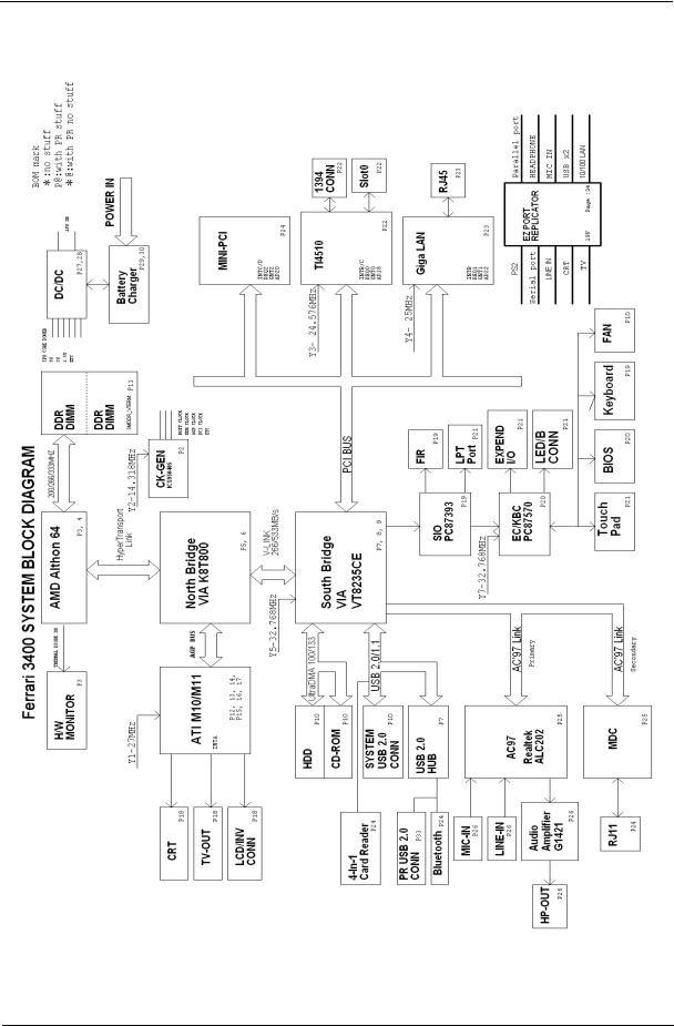
System Block Diagram
Chapter 1 |
3 |
justmanuals.com
Board Layout
Top View
|
2 |
3 |
4 |
5 |
6 |
7 |
|
|
|||||
18 |
1 |
|
|
|
|
8 |
|
|
|
|
|
|
|
17 |
|
|
|
|
|
9 |
|
|
|
|
10 |
|
|
16 |
|
|
|
11 |
|
|
|
|
|
|
12 |
|
|
|
|
|
|
13 |
|
|
|
15 |
|
14 |
|
|
|
1 |
CPU socket |
|
10 |
DIMM Socket |
|
|
2 |
S-video port |
|
11 |
Optical drive connector |
||
3 |
CRT |
|
12 |
Keyboard connector |
|
|
4 |
Printer port |
|
13 |
Main battery connector |
||
5 |
EazyPort connector |
|
14 |
FIR |
|
|
6 |
RJ45 |
|
15 |
HDD connector |
|
|
7 |
RJ11 |
|
16 |
PCMCIA slot |
|
|
8 |
Power jack |
|
17 |
IEEE 1394 port |
|
|
9 |
LCD connector |
|
18 |
Four USB ports |
|
|
4 |
Chapter 1 |

Bottom View
5
1
2
3
4
1Line-in connector
2Microphone-in connector
3Line-out connector
4Mini PCI connector
5DIMM socket
Chapter 1 |
5 |
justmanuals.com
Outlook View
A general introduction of ports allow you to connect peripheral devices, as you would with a desktop PC.
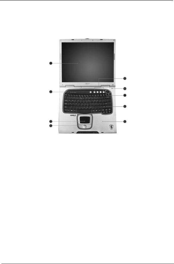
Front Open View
# |
Icon |
Item |
Description |
|
|
|
|
1 |
|
Display screen |
Also called LCD (liquid-crystal display), |
|
|
|
displays computer output. |
|
|
|
|
2 |
|
Power button |
Turns on the computer. |
|
|
|
|
3 |
|
Touchpad |
Touch-sensitive pointing device which |
|
|
|
functions like a computer mouse. |
|
|
|
|
4 |
|
Click buttons (left, |
The left and right buttons function like the |
|
|
center and right) |
left and right mouse buttons; the center |
|
|
|
button serves as a 4-way scroll button. |
|
|
|
|
5 |
|
Palmrest |
Comfortable support area for your hands |
|
|
|
when you use the computer. |
|
|
|
|
6 |
|
Keyboard |
Inputs data into your computer. |
|
|
|
|
7 |
|
Status indicators |
LEDs (light-emitting diode) that turn on and |
|
|
|
off to show the status of the computer, its |
|
|
|
functions and components. |
|
|
|
|
8 |
|
Microphone |
Internal microphone for sound recording. |
|
|
|
|
9 |
|
Launch keys |
Special keys for launching Internet |
|
|
|
browser, E-mail program and frequently |
|
|
|
used programs. Located at the top of the |
|
|
|
keyboard are five buttons. They are |
|
|
|
designated as P1, P2, P3, E-mail button |
|
|
|
and Web browser button. P1, P2 and P3 |
|
|
|
launch user-programmable applications; E- |
|
|
|
mail and Web browser launch E-mail and |
|
|
|
Internet browser applications. |
|
|
|
|
6 |
Chapter 1 |
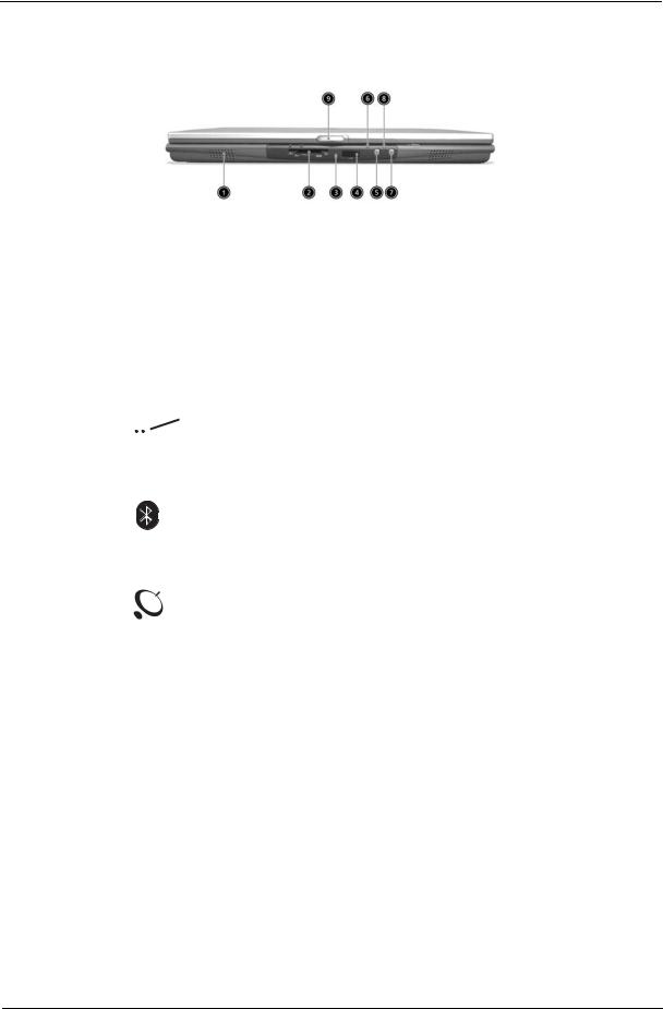
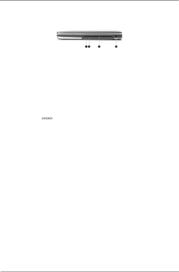
Front Panel
# |
|
|
Icon |
Item |
Description |
||
|
|
|
|
|
|
|
|
1 |
|
|
|
|
|
Speaker |
Outputs sound. |
|
|
|
|
|
|
|
|
2 |
|
|
|
|
|
4-in-1 memory reader |
Reads cards from Smart Media, Memory |
|
|
|
|
|
|
|
Stick, MultiMedia, and Secure Digital cards. |
|
|
|
|
|
|
|
|
3 |
|
|
|
|
|
4-in-1 status indicator |
Displays activity of 4-in-1 memory reader. |
|
|
|
|
|
|
|
|
4 |
|
|
|
|
|
Infrared port |
Interfaces with infrared devices (e.g., infra- |
|
|
|
|
|
|
|
red printer, IR-aware computer). |
|
|
|
|
|
|
|
|
|
|
|
|
|
|
|
|
5 |
|
|
|
|
|
Bluetooth button |
Starts Bluetooth functionality. |
6 |
|
|
|
|
|
Bluetooth indicator |
Indicates that (optional) Bluetooth is |
|
|
|
|
|
|
|
enabled. |
|
|
|
|
|
|
|
|
7 |
|
|
|
|
|
InviLink button |
Enables or disables wireless connectivity. |
8 |
|
|
|
|
|
InviLink indicator |
Indicates status of wireless communication |
|
|
|
|
|
|
|
|
9 |
|
|
|
|
|
Latch |
Latch for opening and closing the laptop. |
NOTE: Only one card can operate at any given time.
Chapter 1 |
7 |
justmanuals.com
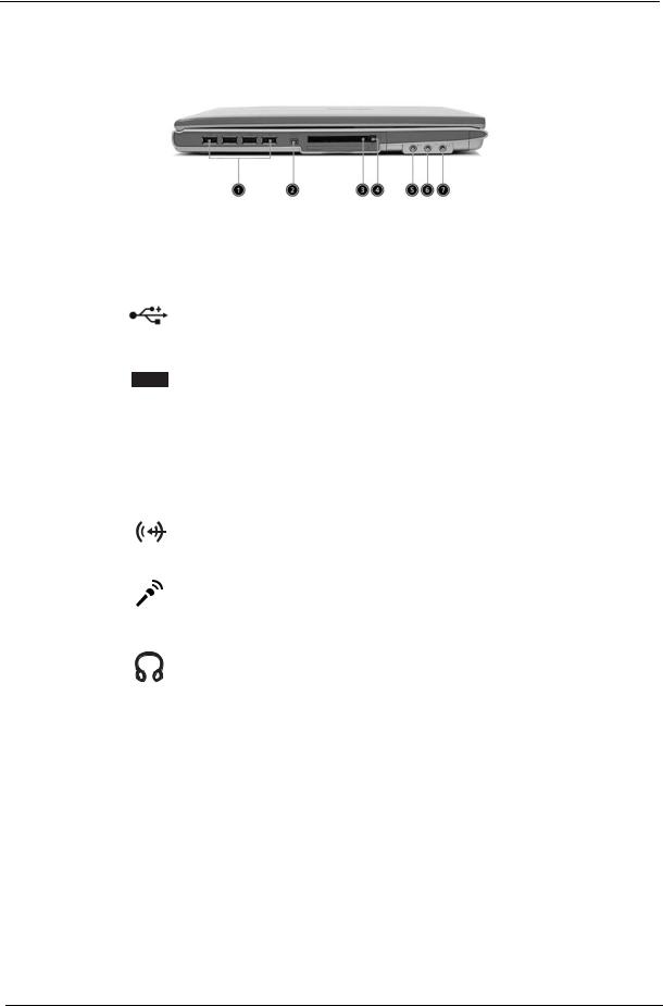
Left Panel
# |
Icon |
Item |
Description |
|||||
|
|
|
|
|
|
|
|
|
1 |
|
|
|
|
|
|
Four (4) USB 2.0 ports |
Connect to Universal Serial Bus devices |
|
|
|
|
|
|
|
|
(e.g., USB mouse, USB camera). |
|
|
|
|
|
|
|
|
|
2 |
|
|
|
|
|
|
IEEE 1394 port |
Connects to IEEE 1394 devices. |
|
|
|
|
|
|
|
|
|
3 |
|
|
|
|
|
|
PC Card slot |
The slot supports a standard Type II |
|
|
|
|
|
|
|
|
CardBus PC Card. |
|
|
|
|
|
|
|
|
|
|
|
|
|
|
|
|
|
|
|
|
|
|
|
|
|
|
|
4 |
|
|
|
|
|
|
PC Card eject button |
Ejects the PC Card from the slot. |
5 |
|
|
|
|
|
|
Line-in jack |
Accepts audio line-in devices (e.g., audio |
|
|
|
|
|
|
|
|
CD player, stereo walkman). |
|
|
|
|
|
|
|
|
|
6 |
|
|
|
|
|
|
Microphone jack |
Accepts input from external microphone. |
|
|
|
|
|
|
|
|
|
7 |
|
|
|
|
|
|
Headphone/Speaker/ |
Connects to headphones or other line-out |
|
|
|
|
|
|
|
Line-out jack |
audio devices (speakers). |
|
|
|
|
|
|
|
|
|
8 |
Chapter 1 |
Right Panel
# |
|
Icon |
Item |
Description |
|||||
|
|
|
|
|
|
|
|
|
|
1 |
|
|
|
|
|
|
|
Slot loading optical |
Press the eject button to remove a disc |
|
|
|
|
|
|
|
|
drive eject button |
from the slot loading optical drive. |
|
|
|
|
|
|
|
|
|
|
2 |
|
|
|
|
|
|
|
Optical disc access |
LED that indicates when an optical disc is |
|
|
|
|
|
|
|
|
indicator |
being read or written. |
|
|
|
|
|
|
|
|
|
|
3 |
|
|
|
|
|
|
|
Optical drive eject |
Press the eject button to remove a disc |
|
|
|
|
|
|
|
|
button |
from the optical drive. |
|
|
|
|
|
|
|
|
|
|
4 |
|
|
|
|
|
|
|
Optical drive |
Used to eject an optical disc when the |
|
|
|
|
|
|
|
|
emergency eject hole |
computer is turned off. |
|
|
|
|
|
|
|
|
|
|
5 |
|
|
|
|
|
|
|
Power jack |
Connects to an AC adapter. |
|
|
|
|
|
|
|
|
|
|
|
|
|
|
|
|
|
|
|
|
|
|
|
|
|
|
|
|
|
|
|
|
|
|
|
|
|
|
|
|
|
|
|
|
|
|
|
|
|
|
Chapter 1 |
9 |
justmanuals.com
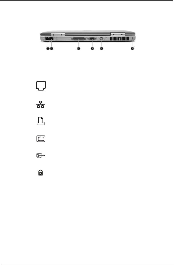
Rear Panel
# |
Icon |
Item |
Description |
|||||
|
|
|
|
|
|
|
|
|
1 |
|
|
|
|
|
|
Modem jack |
Connects to a phone line. |
|
|
|
|
|
|
|
|
|
2 |
|
|
|
|
|
|
Network jack |
Connect to an Ethernet 10/100-based |
|
|
|
|
|
|
|
|
network. |
|
|
|
|
|
|
|
|
|
3 |
|
|
|
|
|
|
Parallel port |
Connects to a parallel device (e.g., parallel |
|
|
|
|
|
|
|
|
printer). |
|
|
|
|
|
|
|
|
|
|
|
|
|
|
|
|
|
|
|
|
|
|
|
|
|
|
|
|
|
|
|
|
|
|
|
|
|
|
|
|
|
|
|
|
|
|
|
|
|
|
|
|
|
|
|
|
|
|
|
|
|
|
|
4 |
|
|
|
|
|
|
External display port |
Connects to a display device (e.g., external |
|
|
|
|
|
|
|
|
monitor, LCD projector). |
|
|
|
|
|
|
|
|
|
5 |
|
|
|
|
|
|
S-video |
Connects t a television or display device |
|
|
|
|
|
|
|
|
with S-video input. |
|
|
|
|
|
|
|
|
|
6 |
|
|
|
|
|
|
Security keylock |
Connects to a Kensington-compatible |
|
|
|
|
|
|
|
|
computer security lock. |
|
|
|
|
|
|
|
|
|
10 |
Chapter 1 |
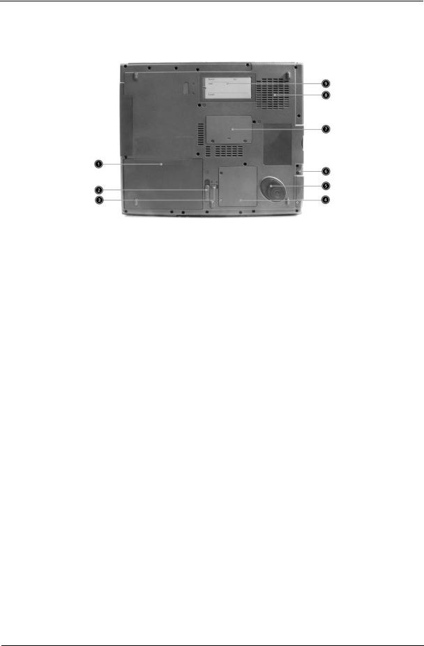
Bottom Panel
# |
Icon |
Item |
Description |
|
|
|
|
1 |
|
Battery bay |
Houses the computer’s battery pack. |
|
|
|
|
2 |
|
Battery release latch |
Unlatches the battery to remove the battery |
|
|
|
pack. |
|
|
|
|
3 |
|
Battery lock |
Locks the battery in place. |
|
|
|
|
4 |
|
Mini-PCI slot |
Slot for adding mini-PCI cards. |
|
|
|
|
5 |
|
Hard disk protector |
Protects the hard disk from accidental |
|
|
|
bumps and vibration. |
|
|
|
|
6 |
|
Hard disk bay |
Houses the computer’s hard disk (secured |
|
|
|
by a screw). |
|
|
|
|
7 |
|
Memory compartment |
Houses th computer’s main memory. |
|
|
|
|
8 |
|
Cooling fan |
Helps keep the computer cool. |
|
|
|
Note: Don’t cover or obstruct the opening |
|
|
|
of the fan. |
|
|
|
|
9 |
|
Personal identification |
Insert a business card or similar-sized |
|
|
slot |
indentification card to presonalize your |
|
|
|
computer. |
|
|
|
|
Chapter 1 |
11 |
justmanuals.com
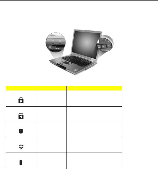
Indicators
The computer has three easy-to-read status indicators below the display screen. And two on the front of the computer.
The Power and Battery status indicators are visible even when the display is closed.
Icon |
Function |
Description |
|
Caps lock |
Lights when Caps Lock is activated. |
|
Num lock |
Lights when Num Lock is activated. |
|
Media Activity |
Lights when the disc or optical drive is |
|
|
activated. |
|
Power |
Lights gree when the power is on and |
|
|
orange when the computer is in standby |
|
|
mode. |
|
Battery |
Lights orange when the battery is charging. |
|
|
|
|
|
|
|
|
12 |
|
Chapter 1 |
|

Using the Keyboard
The full-sized keyboardincludes an embedded numeric keypad, separate cursor keys, two Windows keys and twelve function keys.
Lock Keys
The keyboard has three lock keys which you can toggle on and off.
Lock Key |
Description |
|
|
Caps Lock |
When Caps Lock is on, all alphabetic characters are |
|
typed in uppercase. Toggle on and off by pressing the |
|
Caps Lock key on the left of the keyboard. |
|
|
Num lock |
When Num Lock is on, the embedded numeric keypad |
(Fn-F11) |
can be used. Toggle on and off by pressing the Fn + |
|
F11 keys simultaneously. |
|
|
Scroll lock |
When Scroll Lock is on, the screen moves one line up |
(Fn-F12) |
or down when you press w and y respectively. |
|
|
Chapter 1 |
13 |
justmanuals.com
Embedded Numeric Keypad
The embedded numeric keypad functions like a desktop numeric keypad. It is indicated by small characters located on the upper right corner of the keycaps. To simplify the keyboard legend, cursor-control key symbols are not printed on the keys.
Desired Access |
Num Lock On |
Num Lock Off |
|
|
|
Number keys on embedded |
Type numbers in a normal |
|
keypad |
manner. |
|
|
|
|
Cursor-control keys on |
Hold j while using |
Hold Fn while using cursor- |
embedded keypad |
cursor-control keys. |
control keys. |
|
|
|
Main keyboard keys |
Hold Fn while typing letters |
Type the letters in a normal |
|
on embedded keypad. |
manner. |
|
|
|
14 |
Chapter 1 |
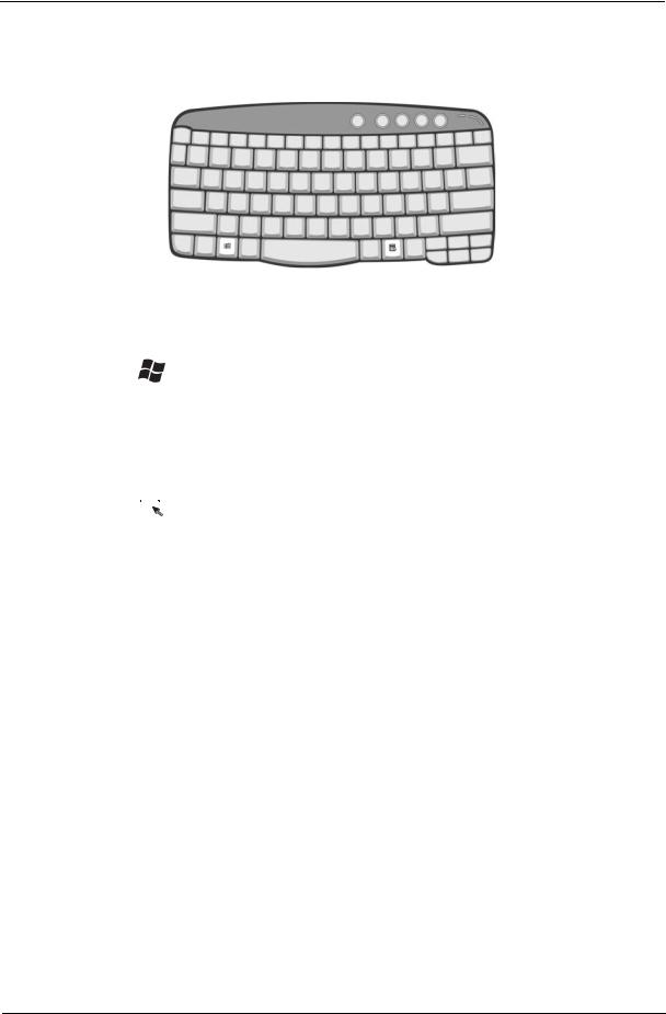
Windows Keys
The keyboard has two keys that perform Windows-specific functions.
Key |
Icon |
Description |
|||
|
|
|
|
|
|
Windows logo |
|
|
|
|
Start button. Combinations with this key perform |
key |
|
|
|
|
special functions. Below are a few examples: |
|
|
|
|
|
+ Tab (Activates next taskbar button) |
|
|
|
|
|
+ E (Explores My Computer) |
|
|
|
|
|
+ F (Finds Document) |
|
|
|
|
|
+ M (Minimizes All) |
|
|
|
|
|
j + Windows logo key + M (Undoes Minimize All) |
|
|
|
|
|
+ R (Displays the Run... dialog box) |
|
|
|
|
|
|
Application |
|
|
|
|
Opens a context menu (same as a right-click). |
key |
|
|
|
|
|
|
|
|
|
|
|
|
|
|
|
|
|
|
|
|
|
|
|
|
|
|
|
|
|
|
|
|
|
|
|
|
|
|
|
|
|
|
|
|
|
|
|
Chapter 1 |
15 |
justmanuals.com
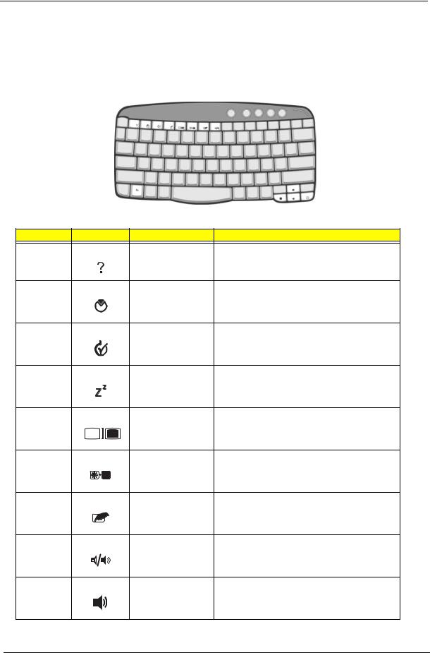
Hot Keys
Using the Fn key with another key creates a hot key, providing a quick and convenient method for controlling various functions.
To activate hot keys, first hold down the Fn key. Next, press the second key in the combination. Finally, release both keys.
Hot Key |
Icon |
Function |
Description |
Fn-F1 |
|
Hot key help |
Displays help on hot keys. |
Fn-F2 |
|
Setup |
Accesses the computer’s configuration utility. |
Fn-F3 |
|
Power management |
Switches the power management scheme used by the |
|
|
scheme toggle |
computer (function available if supported by operating |
|
|
|
system). |
Fn-F4 |
|
Sleep |
Puts the computer in Sleep mode. |
Fn-F5 |
|
Display toggle |
Switches display output between the display screen, |
|
|
|
external monitor (if connected) and both the display |
|
|
|
screen and external monitor. |
Fn-F6 |
|
Screen blank |
Turns the display screen backlight off to save power. |
|
|
|
Press any key to return. |
Fn-F7 |
|
Touchpad toggle |
Turns the internal touchpad on and off. |
Fn-F8 |
|
Speaker toggle |
Turns the speakers on and off. |
Fn-w |
|
Volume up |
Increases the speaker volume. |
16 |
Chapter 1 |

Hot Key |
Icon |
Function |
Description |
Fn-y |
|
Volume down |
Decreases the speaker volume. |
Fn-x |
|
Brightness up |
Increases the screen brightness. |
Fn-z |
|
Brightness down |
Decreases the screen brightness |
Chapter 1 |
17 |
justmanuals.com

The Euro Symbol
If your keyboard layout is set to United States-International or United Kingdom or if you have a keyboard with a European layout, you can type the Euro symbol on your keyboard.
NOTE: For US keyboard users: The keyboard layout is set when you first set up Windows. For the Euro symbol to work, the keyboard layout has to be set to United States-International.
To verify the keyboard type in Windows XP, follow the steps below:
1.Click on Start, Control Panel.
2.Double-click on Regional and Language Options.
3.Click on the Language tab and click on Details.
4.Verify that the keyboard layout used for "En English (United States)" is set to United States-International. If not, select and click on ADD; then select United States-International and click on OK.
5.Click on OK.
To type the Euro symbol:
1.Locate the Euro symbol on your keyboard.
2.Open a text editor or word processor.
3.Hold Alt Gr and press the Euro symbol.
NOTE: Some fonts and software do not support the Euro symbol. Please refer to www.microsoft.com/ typography/faq/faq12.htm for more information.
18 |
Chapter 1 |
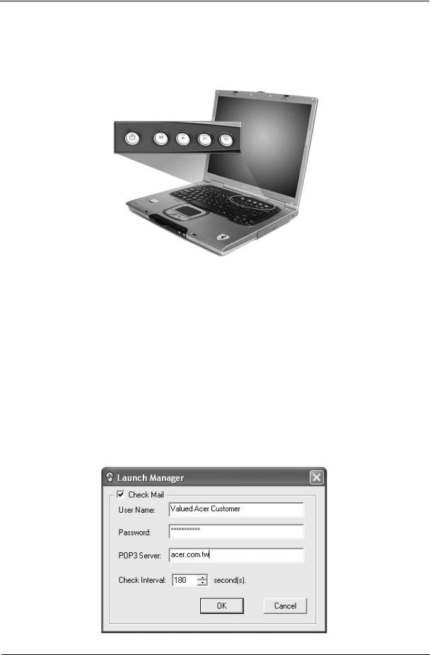
Launch Keys
Located at the top of keyboard are five buttons. The left-most button is the power button. To the right of the power button are the four launch keys. They are designated as the mail button, the web browser button, and two programmable buttons (P1 and P2).
NOTE: To the left of these five launch keys is the wireless communication button. This wireless communication button works for model with 802.11b wireless LAN only.
Launch Key |
Default application |
|
|
Email application |
|
|
|
Web browser |
Internet browser application |
|
|
P1 |
User-programmable |
|
|
P2 |
User-programmable |
|
|
E-mail Detection
Click right button at the Launch Manager icon on the taskbar and click on E-mail Detection. In this dialog box, you have the option to enable disable mail checking, set the time interval for mail checking, etc. If you already have an email account, you can fill in User Name. Password and POP3 Server in the dialog box. The POP3 Server is the mail server where you get your email.
Chapter 1 |
19 |
justmanuals.com
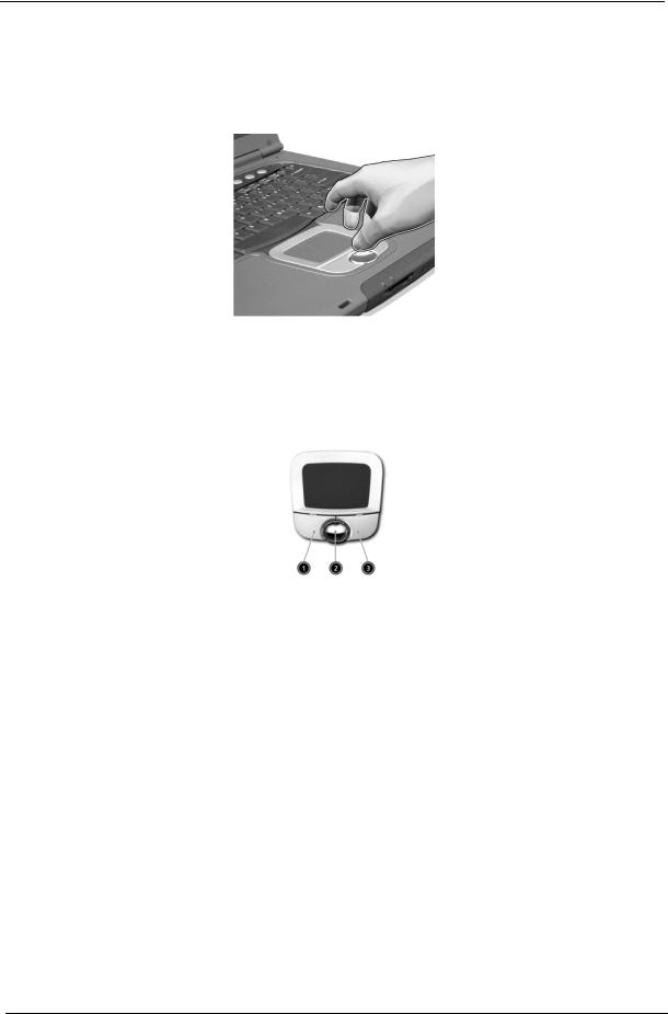
Touchpad
The built-in touchpad is a pointing device that senses movement on its surface. This means the cursor responds as you move your finger on the surface of the touchpad. The central location on the palmrest provides optimal comfort and support.
NOTE: If you are using an external USB mouse, you can press Fn-F7 to disable the touchpad.
Touchpad Basics
The following items teache you how to use the touchpad:
Move your finger across the touchpad to move the cursor.
Press the left (1) and right (3) buttons located on the edge of the touchpad to do selection and execution functions. These two buttons are similar to the left and right buttons on a mouse. Tapping on the touchpad produces similar results.
Use the 4-way scroll (2) button (top/bottom/left/and right) to scrolla page up, down, left or right. This button mimics your cursor pressing on the vertical and horizontal scroll bars of Windows applications.
Function |
Left Button |
Right Button |
Scroll Button |
Tap |
|
|
|
|
|
Execute |
Click twice |
|
|
Tap twice (at the same |
|
quickly |
|
|
speed as double-clicking |
|
|
|
|
the mouse button) |
|
|
|
|
|
Select |
Click once |
|
|
Tap once |
|
|
|
|
|
Drag |
Click and hold, |
|
|
Tap twice (at the same |
|
then use finger |
|
|
speed as double-clicking |
|
to drag the |
|
|
a mouse button) then hold |
|
cursor on the |
|
|
finger to the touchpad on |
|
touchpad |
|
|
the second tap to drag the |
|
|
|
|
cursor |
|
|
|
|
|
Access context |
|
Click once |
|
|
menu |
|
|
|
|
|
|
|
|
|
20 |
Chapter 1 |

Function |
Left Button |
Right Button |
Scroll Button |
Tap |
|
|
|
|
|
Scroll |
|
|
Click and hold |
|
|
|
|
the button in the |
|
|
|
|
desired |
|
|
|
|
direction (up/ |
|
|
|
|
down/left/right) |
|
|
|
|
|
|
NOTE: Keep your fingers dry and clean when using the touchpad. Also keep the touchpad dry and clean. The touchpad is sensitive to finger movements. Hence, the lighter the touch, the better the response. Tapping too hard will not increase the touchpad’s responsiveness.
Chapter 1 |
21 |
justmanuals.com

Hardware Specifications and Configurations
Processor
Item |
Specification |
|
|
CPU type |
AMD Mobile AthlonTM 64 |
CPU package |
packing in 754-pin Lidless µPGA |
|
|
CPU core voltage |
0.9V/1.2V |
|
|
Core logic |
VIA K8T800+VIA VT8235CE |
|
|
BIOS |
|
|
|
Item |
Specification |
|
|
BIOS vendor |
Phneoix |
|
|
BIOS Version |
|
|
|
BIOS ROM type |
Flash ROM |
|
|
BIOS ROM size |
512KB |
|
|
BIOS package |
PLCC |
|
|
Supported protocols |
ACPI 1.0b, PC Card 95, SM BIOS 2.3, EPP/IEEE 1284, ECP/IEEE 1284 |
|
1.7 & 1.9, PCI 2.2, PnP 1.0a, DMI 2.0, PS/2 keyboard and mouse, USB |
|
2.0, VGA BIOS, CD-ROM bootable, IEEE 1394 |
|
|
BIOS password control |
Set by setup manual |
|
|
Second Level Cache |
|
|
|
Item |
Specification |
|
|
Cache controller |
Built-in CPU |
|
|
Cache size |
512KB |
|
|
1st level cache control |
Always enabled |
|
|
2st level cache control |
Always enabled |
|
|
Cache scheme control |
Fixed in write-back |
|
|
System Memory |
|
|
|
Item |
Specification |
|
|
Memory controller |
AMD Mobile AthlonTM 64 built-in |
Memory size |
0MB (no on-board memory) |
|
|
DIMM socket number |
2 sockets |
|
|
Supports memory size per socket |
1024MB |
|
|
Supports maximum memory size |
2048MB (by two 1024MB SO-DIMM module) |
|
|
Supports DIMM type |
DDR Synchronous DRAM |
|
|
Supports DIMM Speed |
333 MHz |
|
|
Supports DIMM voltage |
2.5V |
|
|
Supports DIMM package |
200-pin soDIMM |
|
|
Memory module combinations |
You can install memory modules in any combinations as long as they |
|
match the above specifications. |
|
|
22 |
Chapter 1 |

DIMM Combinations
Slot 1 |
Slot 2 |
Total Memory |
|
|
|
0MB |
256MB |
256MB |
|
|
|
0MB |
512MB |
512MB |
|
|
|
0MB |
1024MB |
1024MB |
|
|
|
256MB |
256MB |
512MB |
|
|
|
256MB |
512MB |
768MB |
|
|
|
256MB |
1024MB |
1280MB |
|
|
|
512MB |
256MB |
768MB |
|
|
|
512MB |
512MB |
1024MB |
|
|
|
512MB |
1024MB |
1536MB |
|
|
|
1024MB |
256MB |
1280MB |
|
|
|
1024MB |
512MB |
1536MB |
|
|
|
1024MB |
1024MB |
2048MB |
|
|
|
NOTE: Above table lists some system memory configurations. You may combine DIMMs with various capacities to form other combinations. On above table, the configuration of slot 1 and slot 2 could be reversed.
LAN Interface
Item |
Specification |
|
|
Chipset |
Broadcom BCM5788M |
|
|
Supports LAN protocol |
10/100/1000 Mbps |
|
|
LAN connector type |
RJ45 |
|
|
LAN connector location |
Rear panel |
|
|
Modem Interface
Item |
Specification |
|
|
Chipset |
South bridge/VIA VT8235CE--controller on the main board |
|
International Agere LU 97 Scorpio+CSP1037B--chipset on |
|
modem board itself |
|
|
Data modem data baud rate (bps) |
56K |
|
|
Supports modem protocol |
V.90/V.92 MDC |
|
|
Modem connector type |
RJ11 |
|
|
Modem connector location |
Rear panel |
|
|
Bluetooth-MODEM Interface
Item |
Specification |
|
|
Chipset |
South bridge/VIA VT8235CE--controller on the mainboard |
|
CSR BC212615BEN-E4/Agere Scorpio solution--chipset on the |
|
combo module itself |
|
|
Data throughput |
200k bps (Blue-tooth)/56K bps (MODEM) |
|
|
Protocol |
Blue-tooth 1.1 |
|
|
Interface |
USB 1.1+MDC |
|
|
Connector type |
RJ11 (MODEM) |
|
|
Support voice function |
Yes/or NO?? |
|
|
Chapter 1 |
23 |
justmanuals.com
Loading...