

Page 1

Acer
Aspire X3990
Service Guide
PRINTED IN TAIWAN
Page 2

ii
Revision History
Please refer to the table below for the updates made on this service guide.
Date Chapter Updates
Page 3

iii
Copyright
Copyright © 2011 by Acer Incorporated. All rights reserved. No part of this publication may be reproduced,
transmitted, transcribed, stored in a retrieval system, or translated into any language or computer language, in
any form or by any means, electronic, mechanical, magnetic, optical, chemical, manual or otherwise, without
the prior written permission of Acer Incorporated.
Page 4
iv
Disclaimer
The information in this guide is subject to change without notice.
Acer Incorporated makes no representations or warranties, either expressed or implied, with respect to the
contents hereof and specifically disclaims any warranties of merchantability or fitness for any particular
purpose. Any Acer Incorporated software described in this manual is sold or licensed "as is". Should the
programs prove defective following their purchase, the buyer (and not Acer Incorporated, its distributor, or its
dealer) assumes the entire cost of all necessary servicing, repair, and any incidental or consequential
damages resulting from any defect in the software.
Acer is a registered trademark of Acer Corporation.
Intel is a registered trademark of Intel Corporation.
Pentium Dual-Core, Celeron Dual-Core, Core 2 Duo, Core 2 Quad, Celeron, and combinations thereof, are
trademarks of Intel Corporation.
Other brand and product names are trademarks and/or registered trademarks of their respective holders.
Page 5
v
Conventions
The following conventions are used in this manual:
SCREEN
MESSAGES
Denotes actual messages that appear on screen.
NOTE Gives additional information related to the current topic.
WARNING Alerts you to any physical risk or system damage that might result from doing
or not doing specific actions.
CAUTION Gives precautionary measures to avoid possible hardware or software
problems.
IMPORTANT Reminds you to do specific actions relevant to the accomplishment of
procedures.
Page 6
vi
Service Guide Coverage
This Service Guide provides you with all technical information relating to the BASIC CONFIGURATION
decided for Acer's "global" product offering. To better fit local market requirements and enhance product
competitiveness, your regional office MAY have decided to extend the functionality of a machine (e.g. add-on
card, modem, or extra memory capability). These LOCALIZED FEATURES will NOT be covered in this generic
service guide. In such cases, please contact your regional offices or the responsible personnel/channel to
provide you with further technical details.
FRU Information
Please note WHEN ORDERING FRU PARTS, that you should check the most up-to-date information available
on your regional web or channel. If, for whatever reason, a part number change is made, it will not be noted in
the printed Service Guide. For ACER-AUTHORIZED SERVICE PROVIDERS, your Acer office may have a
DIFFERENT part number code to those given in the FRU list of this printed Service Guide. You MUST use the
list provided by your regional Acer office to order FRU parts for repair and service of customer machines.
Page 7
vii
System Tour 1
Features 1
Block Diagram 4
System Components 5
Front Panel 5
Rear Panel 6
Hardware Specifications and Configurations 7
Power Management Function(ACPI support function) 11
System Utilities 12
CMOS Setup Utility 12
Entering CMOS setup 13
Navigating Through the Setup Utility 13
Setup Utility Menus 14
Main 14
System Disassembly and Assembly 24
Disassembly Requirements 24
Pre-disassembly Procedure 25
Removing the Side Panel 26
Removing the Heat Sink Fan Assembly 27
Removing the Processor 29
Removing the TV-Tuner Card 31
Removing the VGA Card 32
Removing the Front Bezel 33
Removing the Cage of ODD and HDD 34
Removing the Hard Disk Drive 37
Removing the Optical Drive 38
Removing the Memory Modules 39
Removing the Power Supply 40
Removing the Mainboard 42
Removing the
Front I/O&USB and Card Reader Boards 45
Assembly Requirements 48
Assembly Procedure 49
Install the Processor 50
Install the Memory 51
Install the Heat Sink Fan Assembly 52
Romoving the Side Panel 53
Romoving the Front Bezel 54
Removing the Cage of ODD and HDD 55
Install the Power Supply 56
Install the I/O Shielding 57
Install the Main Board 58
Connect the Cable 59
Install the Optical Drive 61
Install the Hard Disk Drive 62
Install the Cage of ODD and HDD 63
Install the Front Bezel 65
Install the VGA Card 66
Install the TV-Tuner 67
Install the Side Panel 68
Table of Contents
Page 8
viii
System Troubleshooting 69
Hardware Diagnostic Procedure 69
System Check Procedures 70
Power System Check 70
System External Inspection 70
System Internal Inspection 70
Beep Codes 71
Checkpoints 72
BIOS Recovery 75
Jumper and Connector Information 76
M/B Placement 76
Jumper Setting 78
Setting Jumper 78
FRU (Field Replaceable Unit) List 85
Aspire X3990 Exploded Diagram 86
Aspire X3990 FRU List 88
Page 9
Chapter 1 1
Features
Below is a brief summary of the computer’s many feature:
NOTE: The features listed in this section is for your reference only. The exact configuration of the system
depends on the model purchased.
Operating System
• Microsoft Windows 7 Home Premium (X64/X86)
• Microsoft Windows 7 Home Basic (X64/X86)
• Microsoft Windows 7 Starter X86
• Linpus Xwindows
• FreeDos
Processor
• Socket Type: Intel LGA1155
• Socket Quantity: 1
• Processor Type:Intel Sandy Bridge processor.
Chipset
• Intel H61
PCB Size
• DTX, max 4 Layers
Memory subsystem
• Socket Type: DDR III
• Socket Quantity: 2
• 1 channels, 2 DIMMs
• Dual channel should be enabled always when plug-in 2 same memory size DDRIII. memory module.
• Max memory of 8 GB supported (using 4Gb tech).
• Support DDR3 1.5V 1066/1333 (1GB / 2GB / 4GB).
Graphic
• Intel® HD Graphics Support (supported by CPU).
• Dual independent display.
• Digital display (HDMI/DVI/DP/eDP) and VGA.
• DVMT 5.0 technology support.
• Enhanced 3D and Clear Video technology support.
• Need to measure VGA follow Acer VGA SOP.
System Tour
Chapter 1
Page 10
2 Chapter 1
Hard disk drive
• Support up to 2 SATA ports. 3.5”, 25.4mm.
• Capacity and models are listed on AVLC.
Optical disk drive
• Support up to one SATA 5.25” standard ODD.
• Support DVD-ROM, DVD-SuperMulti, BD-combo, BD-rewrite.
• Maximum ODD depth to 185mm with bezel.
• Support models are listed on AVLC.
Graphics card support requirement
• No mechanical restriction.
Serial ATA controller
• Connector Type: SATA connector.
• Connector Quantity: 2
• Storage Type support:
• HDD : Support RAID 0/1/5/10.
• Blue Ray ODD.
• AHCI/RAID mode supported for internal SATA port.
Audio
• Realtek ALC662VC-0.
• Support stereo output. (5.1 channel with SW re-tasking).
LAN
• Intel Lewisville 82579V GigaLAN PHY
USB ports
• Supports at least 10 USB ports on both front and rear side.
• At least 6 USB ports located on rear panel and others located on front bezel and top bezel.
• All USB ports must be boot-capable includes USB-ODD, USB-HDD, USB-FDD, and etc…
• All USB ports must be 2.0 certified.
• All USB ports must provide the over current protection.
• Support USB QTY is vary by different chassis(W/CR USB 2 ports).
Extension slot
• 1 * PCIE x16 (PCIE V2.0).
• 1 * PCIE x1 (PCIE V2.0).
Buzzer
• 1 on board buzzer
Page 11
Chapter 1 3
Rear I/O connectors
• 1 * PS2 KB+MS
• 1 * VGA connector
• 1 * HDMI
• 1 * RJ45 + Dual USB2.0
• 1 * Qual USB2.0 connector (4 ports)
• 1 * 3 ports Audio jack
On-board connectors
• 1 * ILM for LGA 1155 CPU.
• 1 * 24-pin ATX PWR connector.
• 1 * H2X4 Power Supply Connector.
• 2* DDR3 DIMM Socket.
• 2 * SATA 2.0.
• 4 * USB2.0 H5X2 Header (support 8 ports).
• 1 * Front Audio Pannel H5X2 header.
• 1 * Front Panel IO H7X2 Header for Acer pin define.
• 1 * H1X4 CPU with SAMRT FAN controller.
• 1 * H1X4 System with SAMRT FAN controller.
• 1 * H1X4 SPDIFOUT Header for Acer pin define.
• 1 * H3X1 Clear CMOS Header (with jumper).
• 1 * onboard Buzzer.
• 2 * H1X2 GPIO header.
• 1 * 3pin ME enable / disable connector ( Jumper).
System BIOS
• Type: Use SPI Flash
• Size: 32Mb
• Kernel: AMI Kernel with Acer skin
Power supply
• Non PFC 220W / PFC 220W
• FR 220W.
• Support models are listed on AVLC.
Page 12
4 Chapter 1
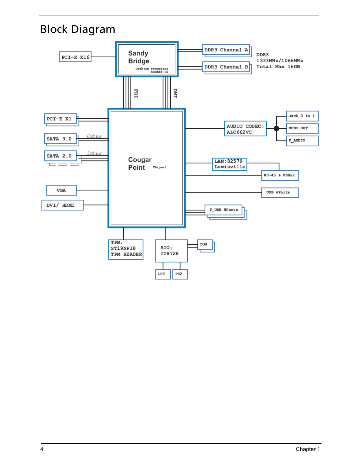
Block Diagram
Page 13
Chapter 1 5
System Components
This section is a virtual tour of the system’s interior and exterior components.
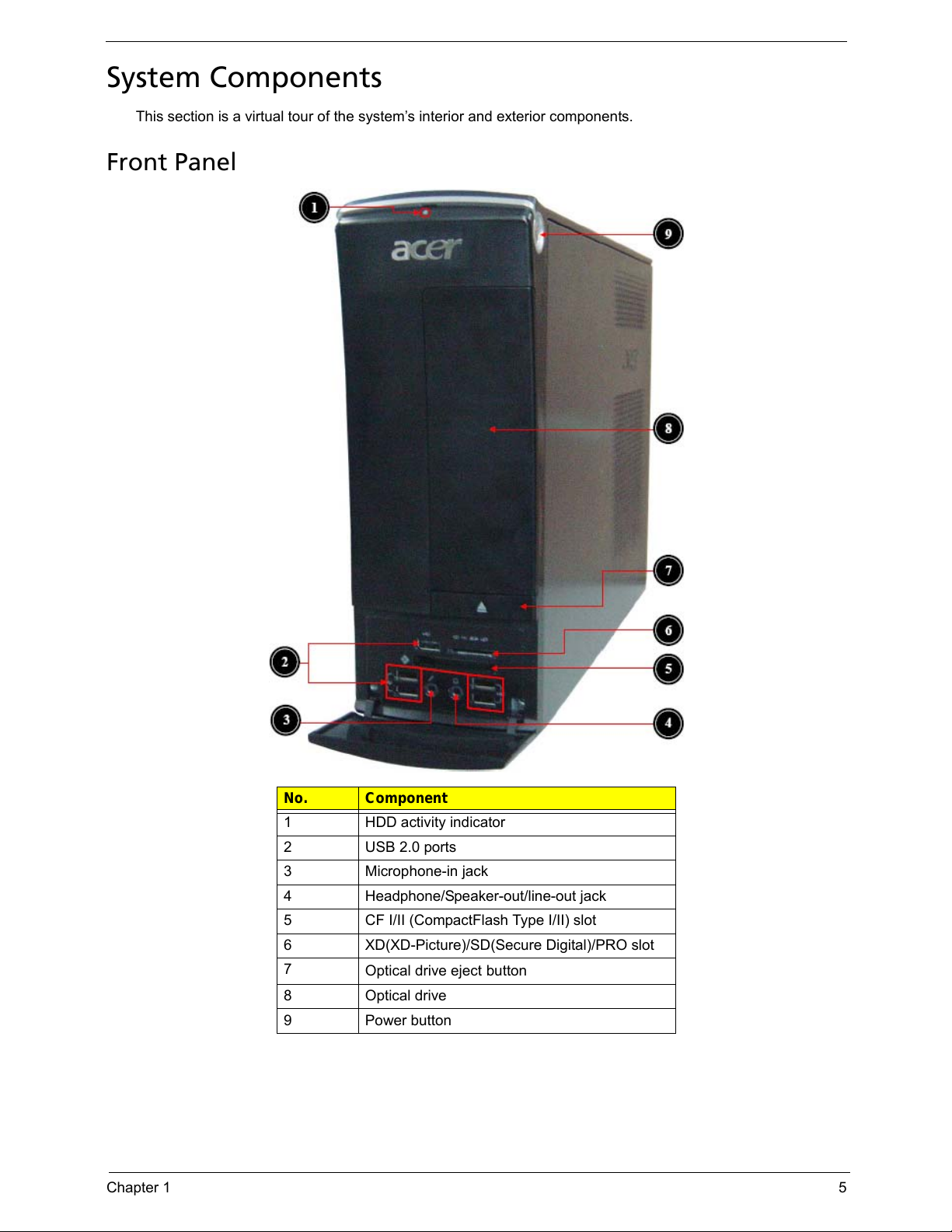
Front Panel
No. Component
1 HDD activity indicator
2 USB 2.0 ports
3 Microphone-in jack
4 Headphone/Speaker-out/line-out jack
5 CF I/II (CompactFlash Type I/II) slot
6 XD(XD-Picture)/SD(Secure Digital)/PRO slot
7
Optical drive eject
button
8 Optical drive
9 Power button
Page 14
6 Chapter 1
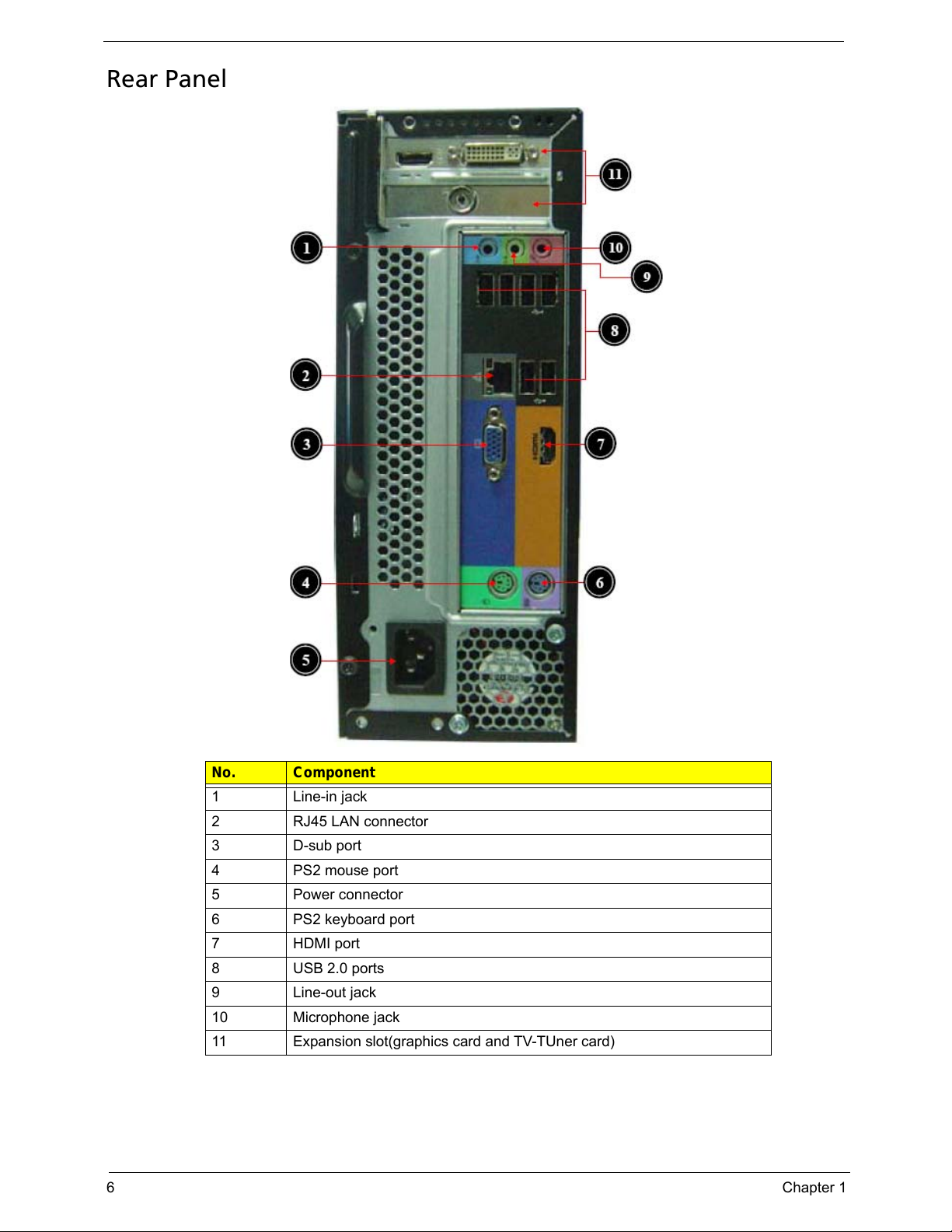
Rear Panel
No. Component
1 Line-in jack
2 RJ45 LAN connector
3 D-sub port
4 PS2 mouse port
5 Power connector
6 PS2 keyboard port
7 HDMI port
8 USB 2.0 ports
9 Line-out jack
10 Microphone jack
11 Expansion slot(graphics card and TV-TUner card)
Page 15
Chapter 1 7
Hardware Specifications and Configurations
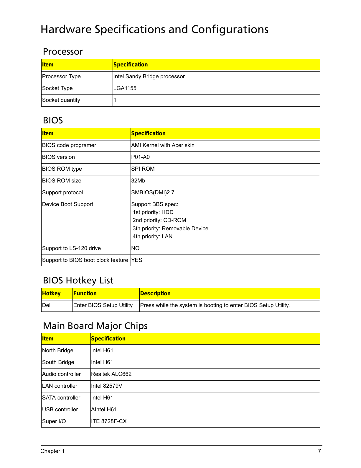
Processor
BIOS
BIOS Hotkey List
Main Board Major Chips
Item Specification
Processor Type Intel Sandy Bridge processor
Socket Type LGA1155
Socket quantity 1
Item Specification
BIOS code programer AMI Kernel with Acer skin
BIOS version P01-A0
BIOS ROM type SPI ROM
BIOS ROM size 32Mb
Support protocol SMBIOS(DMI)2.7
Device Boot Support Support BBS spec:
1st priority: HDD
2nd priority: CD-ROM
3th priority: Removable Device
4th priority: LAN
Support to LS-120 drive NO
Support to BIOS boot block feature YES
Hotkey Function Description
Del Enter BIOS Setup Utility Press while the system is booting to enter BIOS Setup Utility.
Item Specification
North Bridge Intel H61
South Bridge Intel H61
Audio controller Realtek ALC662
LAN controller Intel 82579V
SATA controller Intel H61
USB controller AIntel H61
Super I/O ITE 8728F-CX
Page 16
8 Chapter 1
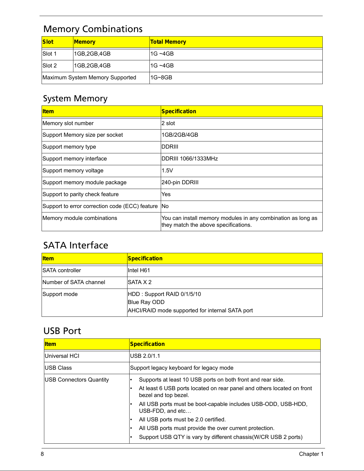
Memory Combinations
System Memory
SATA Interface
USB Port
Slot Memory Total Memory
Slot 1 1GB,2GB,4GB 1G ~4GB
Slot 2 1GB,2GB,4GB 1G ~4GB
Maximum System Memory Supported 1G~8GB
Item Specification
Memory slot number 2 slot
Support Memory size per socket 1GB/2GB/4GB
Support memory type DDRIII
Support memory interface DDRIII 1066/1333MHz
Support memory voltage 1.5V
Support memory module package 240-pin DDRIII
Support to parity check feature Yes
Support to error correction code (ECC) feature No
Memory module combinations You can install memory modules in any combination as long as
they match the above specifications.
Item Specification
SATA controller Intel H61
Number of SATA channel SATA X 2
Support mode HDD : Support RAID 0/1/5/10
Blue Ray ODD
AHCI/RAID mode supported for internal SATA port
Item Specification
Universal HCI USB 2.0/1.1
USB Class Support legacy keyboard for legacy mode
USB Connectors Quantity • Supports at least 10 USB ports on both front and rear side.
• At least 6 USB ports located on rear panel and others located on front
bezel and top bezel.
• All USB ports must be boot-capable includes USB-ODD, USB-HDD,
USB-FDD, and etc…
• All USB ports must be 2.0 certified.
• All USB ports must provide the over current protection.
• Support USB QTY is vary by different chassis(W/CR USB 2 ports)
Page 17
Chapter 1 9
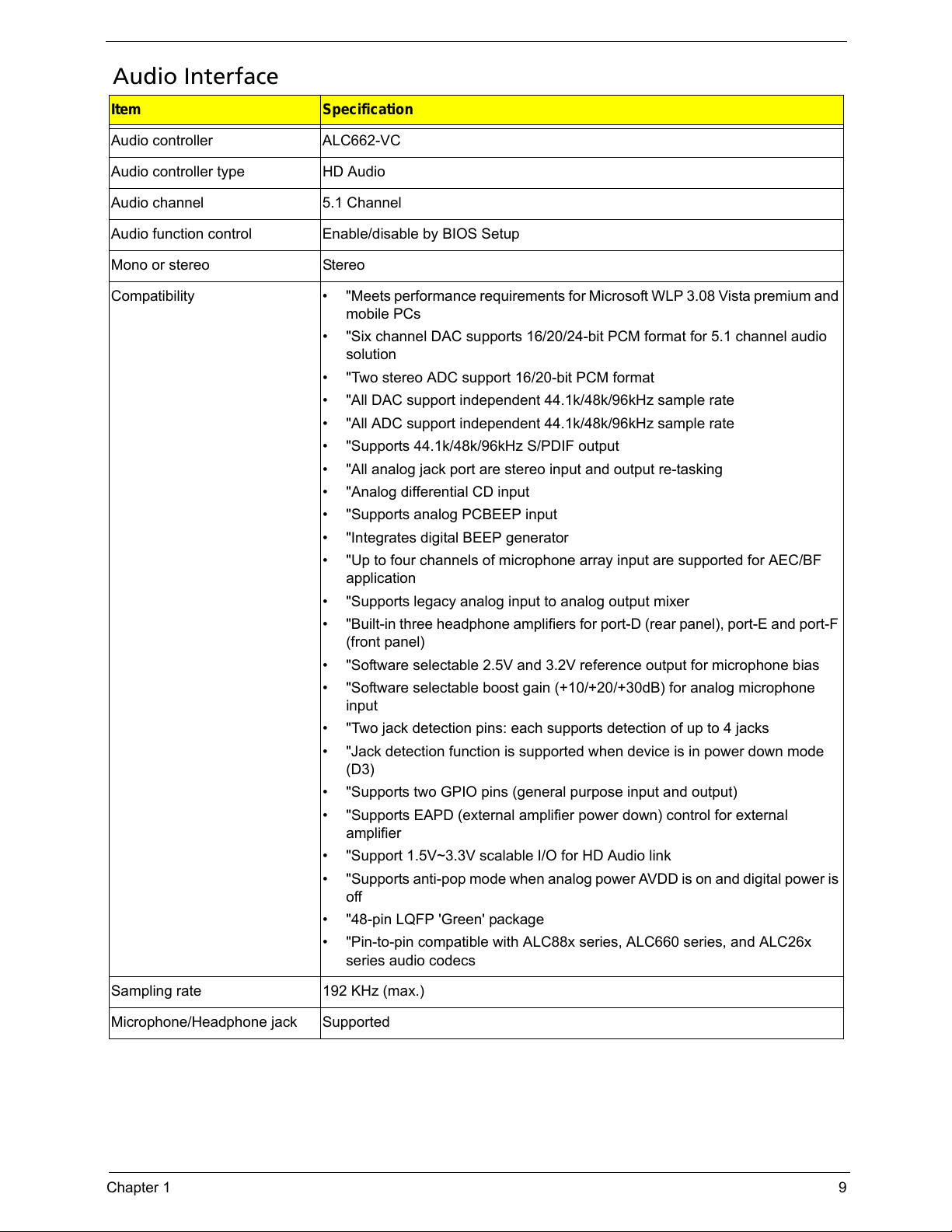
Audio Interface
Item Specification
Audio controller ALC662-VC
Audio controller type HD Audio
Audio channel 5.1 Channel
Audio function control Enable/disable by BIOS Setup
Mono or stereo Stereo
Compatibility • "Meets performance requirements for Microsoft WLP 3.08 Vista premium and
mobile PCs
• "Six channel DAC supports 16/20/24-bit PCM format for 5.1 channel audio
solution
• "Two stereo ADC support 16/20-bit PCM format
• "All DAC support independent 44.1k/48k/96kHz sample rate
• "All ADC support independent 44.1k/48k/96kHz sample rate
• "Supports 44.1k/48k/96kHz S/PDIF output
• "All analog jack port are stereo input and output re-tasking
• "Analog differential CD input
• "Supports analog PCBEEP input
• "Integrates digital BEEP generator
• "Up to four channels of microphone array input are supported for AEC/BF
application
• "Supports legacy analog input to analog output mixer
• "Built-in three headphone amplifiers for port-D (rear panel), port-E and port-F
(front panel)
• "Software selectable 2.5V and 3.2V reference output for microphone bias
• "Software selectable boost gain (+10/+20/+30dB) for analog microphone
input
• "Two jack detection pins: each supports detection of up to 4 jacks
• "Jack detection function is supported when device is in power down mode
(D3)
• "Supports two GPIO pins (general purpose input and output)
• "Supports EAPD (external amplifier power down) control for external
amplifier
• "Support 1.5V~3.3V scalable I/O for HD Audio link
• "Supports anti-pop mode when analog power AVDD is on and digital power is
off
• "48-pin LQFP 'Green' package
• "Pin-to-pin compatible with ALC88x series, ALC660 series, and ALC26x
series audio codecs
Sampling rate 192 KHz (max.)
Microphone/Headphone jack Supported
Page 18
10 Chapter 1
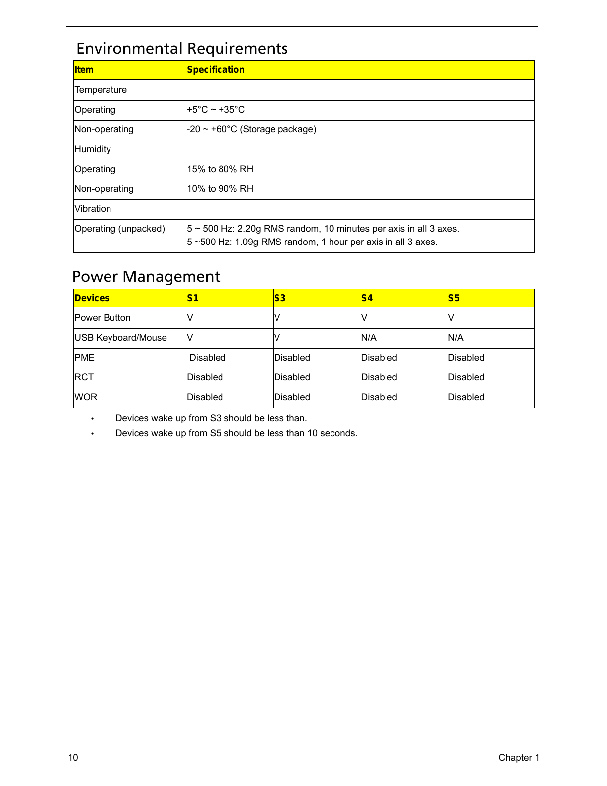
Environmental Requirements
Power Management
• Devices wake up from S3 should be less than.
• Devices wake up from S5 should be less than 10 seconds.
Item Specification
Temperature
Operating +5°C ~ +35°C
Non-operating -20 ~ +60°C (Storage package)
Humidity
Operating 15% to 80% RH
Non-operating 10% to 90% RH
Vibration
Operating (unpacked) 5 ~ 500 Hz: 2.20g RMS random, 10 minutes per axis in all 3 axes.
5 ~500 Hz: 1.09g RMS random, 1 hour per axis in all 3 axes.
Devices S1 S3 S4 S5
Power ButtonVVVV
USB Keyboard/Mouse V V N/A N/A
PME Disabled Disabled Disabled Disabled
RCT Disabled Disabled Disabled Disabled
WOR Disabled Disabled Disabled Disabled
Page 19
Chapter 1 11
Power Management Function(ACPI support function)
Device Standby Mode
• Independent power management timer for hard disk drive devices(0-15 minutes,time step=1minute).
• Hard Disk drive goes into Standby mode(for ATA standard interface).
• Disable V-sync to control the VESA DPMS monitor.
• Resume method:device activated (keyboard for DOS, keyboard &mouse for Windows.
• Resume recovery time 3-5sec
Global Standby Mode
• Global power management timer(2-120minutes,time step=10minute).
• Hard disk drive goes into Standby mode(for ATA standard interface).
• Disable H-sync and V-sync signals to control the VESA DPMS monitor.
• Resume method: Resume to original state by pushing external switch Button,modem ring in,keyboard
an mouse for APM mode.
• Resume recovery time :7-10sec
Suspend Mode
• Independent power management timer(2-120minutes,time step=10minute)or pushing extern switch
button.
• CPU goes into SMM
• CPU asserts STPCLK# and goes into the Stop Grant State.
• LED on panel turns amber colour.
• Hard disk drive goes into SLEEP mode (for ATA standard interface).
• Disable H-sync and V-sync signals to control the VESA DPMS monitor.
• Ultra I/O and VGA chip go into power saving mode.
• Resume method: Resume to original state by pushing external switch Button,modem ring in,keyboard
an mouse for APM mode
• Return to original state by pushing external switch button,modem ring in and USB keyboard for ACPI
mode.
ACPI
• ACPI specification 1.0b
• S0,S1,S2 and S5 sleep state support.
• On board device power management support.
• On board device configuration support.
Page 20
Chapter 2 12
CMOS Setup Utility
CMOS setup is a hardware configuration program built into the system ROM, called the complementary metal-
oxide semiconductor (CMOS) Setup Utility. Since most systems are already properly configured and
optimized, there is no need to run this utility. You will need to run this utility under the following conditions.
• When changing the system configuration settings
• When redefining the communication ports to prevent any conflicts
• When modifying the power management configuration
• When changing the password or making other changes to the security setup
• When a configuration error is detected by the system and you are prompted ("Run Setup"
message) to make changes to the CMOS setup
NOTE: If you repeatedly receive Run Setup messages, the battery may be bad. In this case, the system
cannot retain configuration values in CMOS. Ask a qualified technician for assistance.
CMOS setup loads the configuration values in a battery-backed nonvolatile memory called CMOS RAM. This
memory area is not part of the system RAM which allows configuration data to be retained when power is
turned off.
Before you run the CMOS Setup Utility, make sure that you have saved all open files. The system reboots
immediately after you close the Setup.
NOTE: CMOS Setup Utility will be simply referred to as “BIOS”, "Setup", or "Setup utility" in this guide.
The screenshots used in this guide display default system values. These values may not be the same
those found in your system.
System Utilities
Chapter 2
Page 21
13 Chapter 2
Entering CMOS setup
1. Turn on the server and the monitor.
If the server is already turned on, close all open applications, then restart the server.
2. During POST, press Delete.
If you fail to press Delete before POST is completed, you will need to restart the server.
The Setup Main menu will be displayed showing the Setup’s menu bar. Use the left and right arrow keys
to move between selections on the menu bar.
Navigating Through the Setup Utility
Use the following keys to move around the Setup utility.
• Left and Right arrow keys – Move between selections on the menu bar.
• Up and Down arrow keys – Move the cursor to the field you want.
• PgUp and PgDn keys – Move the cursor to the previous and next page of a multiple page menu.
• Home – Move the cursor to the first page of a multiple page menu.
• End – Move the cursor to the last page of a multiple page menu.
• + and - keys – Select a value for the currently selected field (only if it is user-configurable). Press
these keys repeatedly to display each possible entry, or the Enter key to choose from a pop-up
menu.
NOTE: Grayed-out fields are not user-configurable.
• Enter key – Display a submenu screen.
NOTE: Availability of submenu screen is indicated by a (>).
• Esc – If you press this key:
• On one of the primary menu screens, the Exit menu displays.
• On a submenu screen, the previous screen displays.
• When you are making selections from a pop-up menu, closes the pop-up without making a
selection.
• F1 – Display the General Help panel.
• F6 – Press to load optimized default system values.
• F7 – Press to load fail-safe default system values.
• F10 – Save changes made the Setup and close the utility.
Page 22
Chapter 2 14
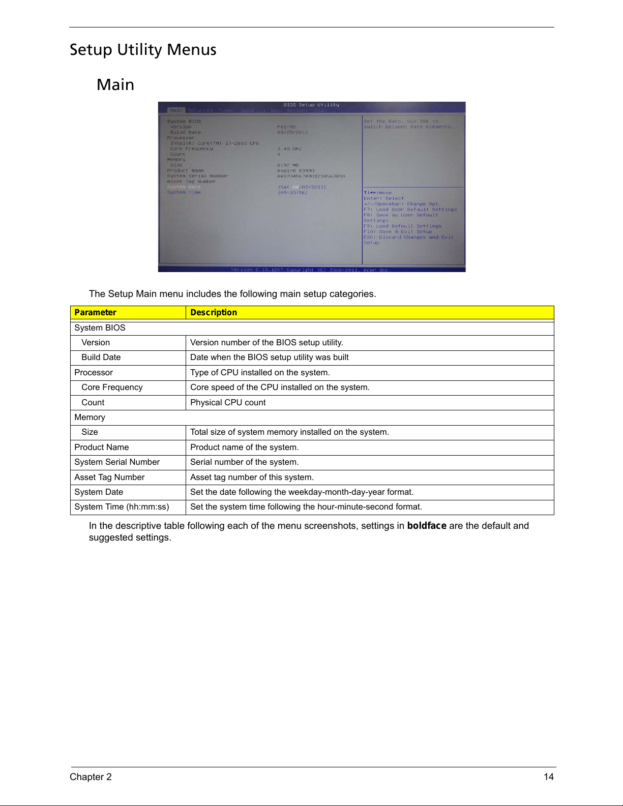
Setup Utility Menus
Main
The Setup Main menu includes the following main setup categories.
In the descriptive table following each of the menu screenshots, settings in boldface are the default and
suggested settings.
Parameter Description
System BIOS
Version Version number of the BIOS setup utility.
Build Date Date when the BIOS setup utility was built
Processor Type of CPU installed on the system.
Core Frequency Core speed of the CPU installed on the system.
Count Physical CPU count
Memory
Size Total size of system memory installed on the system.
Product Name Product name of the system.
System Serial Number Serial number of the system.
Asset Tag Number Asset tag number of this system.
System Date Set the date following the weekday-month-day-year format.
System Time (hh:mm:ss) Set the system time following the hour-minute-second format.
Page 23
15 Chapter 2
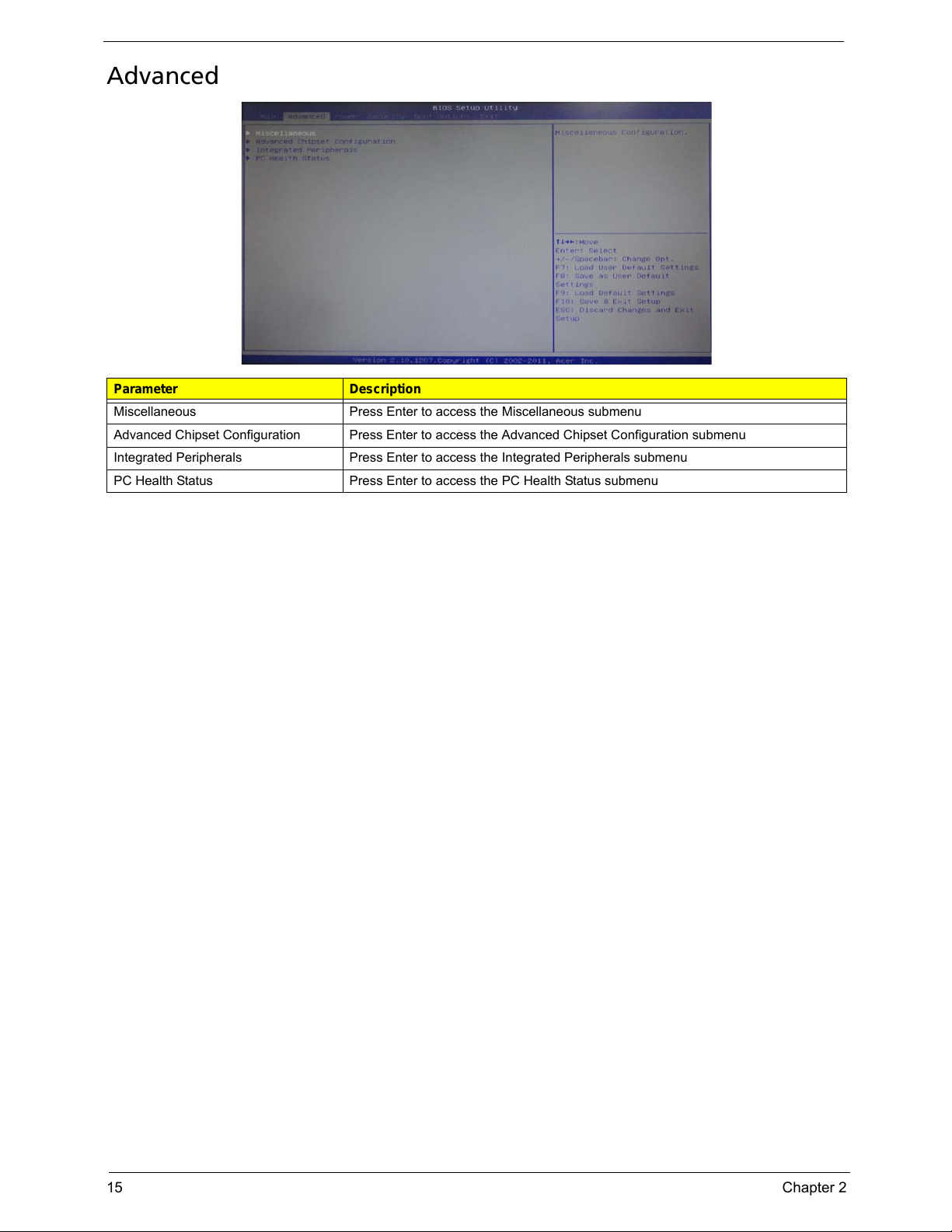
Advanced
Parameter Description
Miscellaneous Press Enter to access the Miscellaneous submenu
Advanced Chipset Configuration Press Enter to access the Advanced Chipset Configuration submenu
Integrated Peripherals Press Enter to access the Integrated Peripherals submenu
PC Health Status Press Enter to access the PC Health Status submenu
Page 24
Chapter 2 16
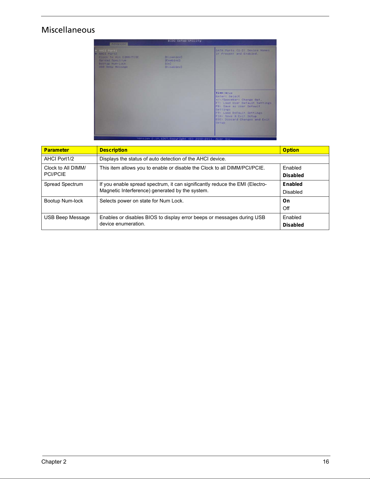
Miscellaneous
Parameter Description Option
AHCI Port1/2 Displays the status of auto detection of the AHCI device.
Clock to All DIMM/
PCI/PCIE
This item allows you to enable or disable the Clock to all DIMM/PCI/PCIE. Enabled
Disabled
Spread Spectrum If you enable spread spectrum, it can significantly reduce the EMI (Electro-
Magnetic Interference) generated by the system.
Enabled
Disabled
Bootup Num-lock Selects power on state for Num Lock. On
Off
USB Beep Message Enables or disables BIOS to display error beeps or messages during USB
device enumeration.
Enabled
Disabled
Page 25
17 Chapter 2
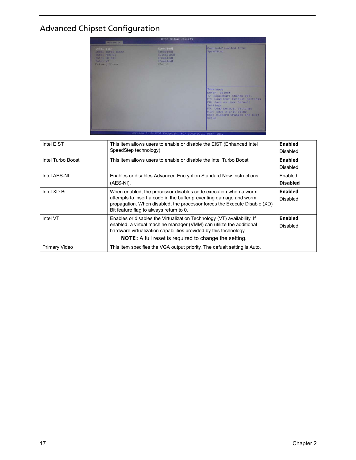
Advanced Chipset Configuration
Intel EIST This item allows users to enable or disable the EIST (Enhanced Intel
SpeedStep technology).
Enabled
Disabled
Intel Turbo Boost This item allows users to enable or disable the Intel Turbo Boost. Enabled
Disabled
Intel AES-NI Enables or disables Advanced Encryption Standard New Instructions
(AES-NI).
Enabled
Disabled
Intel XD Bit When enabled, the processor disables code execution when a worm
attempts to insert a code in the buffer preventing damage and worm
propagation. When disabled, the processor forces the Execute Disable (XD)
Bit feature flag to always return to 0.
Enabled
Disabled
Intel VT Enables or disables the Virtualization Technology (VT) availability. If
enabled, a virtual machine manager (VMM) can utilize the additional
hardware virtualization capabilities provided by this technology.
NOTE: A full reset is required to change the setting.
Enabled
Disabled
Primary Video This item specifies the VGA output priority. The defualt setting is Auto.
Page 26
Chapter 2 18
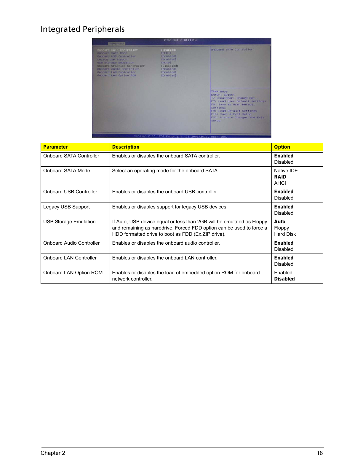
Integrated Peripherals
Parameter Description Option
Onboard SATA Controller Enables or disables the onboard SATA controller. Enabled
Disabled
Onboard SATA Mode Select an operating mode for the onboard SATA. Native IDE
RAID
AHCI
Onboard USB Controller Enables or disables the onboard USB controller. Enabled
Disabled
Legacy USB Support Enables or disables support for legacy USB devices. Enabled
Disabled
USB Storage Emulation If Auto, USB device equal or less than 2GB will be emulated as Floppy
and remaining as harddrive. Forced FDD option can be used to force a
HDD formatted drive to boot as FDD (Ex.ZIP drive).
Auto
Floppy
Hard Disk
Onboard Audio Controller Enables or disables the onboard audio controller. Enabled
Disabled
Onboard LAN Controller Enables or disables the onboard LAN controller. Enabled
Disabled
Onboard LAN Option ROM Enables or disables the load of embedded option ROM for onboard
network controller.
Enabled
Disabled
Page 27
19 Chapter 2
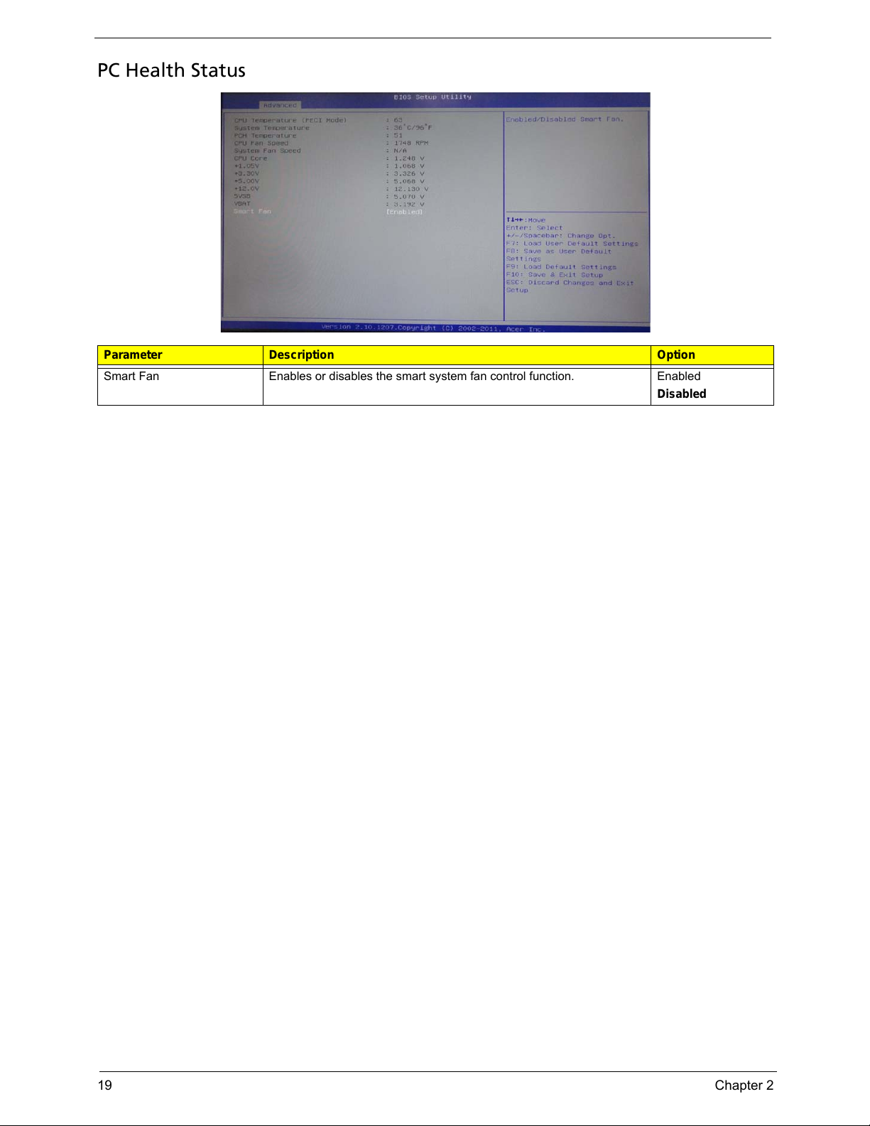
PC Health Status
Parameter Description Option
Smart Fan Enables or disables the smart system fan control function. Enabled
Disabled
Page 28
Chapter 2 20
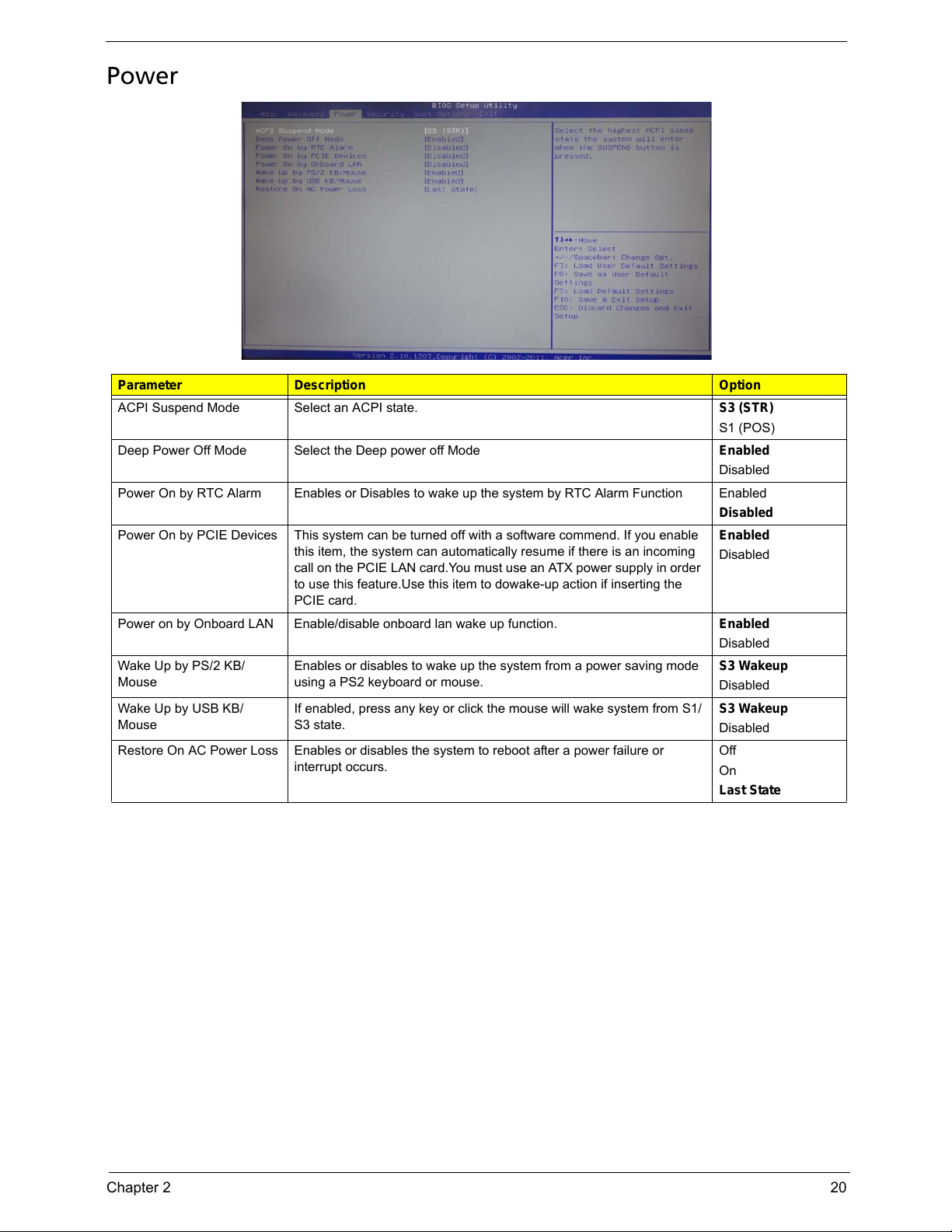
Power
Parameter Description Option
ACPI Suspend Mode Select an ACPI state. S3 (STR)
S1 (POS)
Deep Power Off Mode Select the Deep power off Mode Enabled
Disabled
Power On by RTC Alarm Enables or Disables to wake up the system by RTC Alarm Function Enabled
Disabled
Power On by PCIE Devices This system can be turned off with a software commend. If you enable
this item, the system can automatically resume if there is an incoming
call on the PCIE LAN card.You must use an ATX power supply in order
to use this feature.Use this item to dowake-up action if inserting the
PCIE card.
Enabled
Disabled
Power on by Onboard LAN Enable/disable onboard lan wake up function. Enabled
Disabled
Wake Up by PS/2 KB/
Mouse
Enables or disables to wake up the system from a power saving mode
using a PS2 keyboard or mouse.
S3 Wakeup
Disabled
Wake Up by USB KB/
Mouse
If enabled, press any key or click the mouse will wake system from S1/
S3 state.
S3 Wakeup
Disabled
Restore On AC Power Loss Enables or disables the system to reboot after a power failure or
interrupt occurs.
Off
On
Last State
Page 29
21 Chapter 2
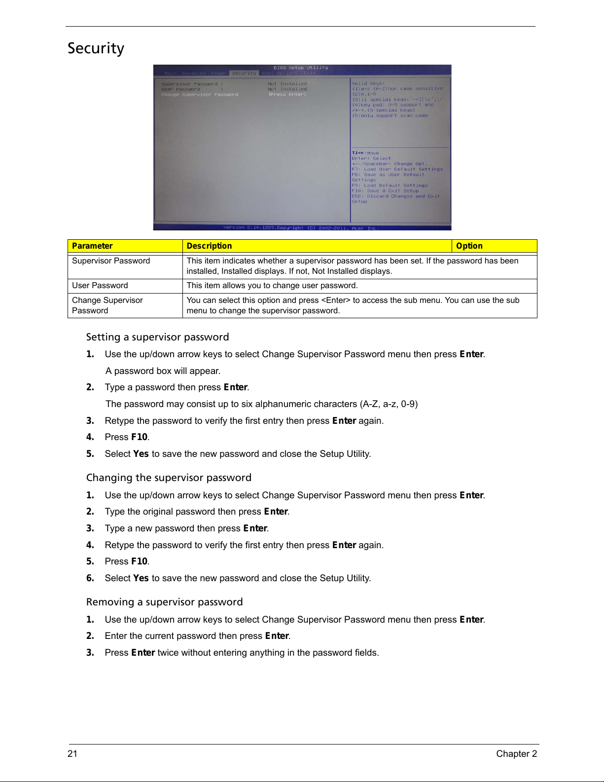
Security
Setting a supervisor password
1. Use the up/down arrow keys to select Change Supervisor Password menu then press Enter.
A password box will appear.
2. Type a password then press Enter.
The password may consist up to six alphanumeric characters (A-Z, a-z, 0-9)
3. Retype the password to verify the first entry then press Enter again.
4. Press F10.
5. Select Yes to save the new password and close the Setup Utility.
Changing the supervisor password
1. Use the up/down arrow keys to select Change Supervisor Password menu then press Enter.
2. Type the original password then press Enter.
3. Type a new password then press Enter.
4. Retype the password to verify the first entry then press Enter again.
5. Press F10.
6. Select Yes to save the new password and close the Setup Utility.
Removing a supervisor password
1. Use the up/down arrow keys to select Change Supervisor Password menu then press Enter.
2. Enter the current password then press Enter.
3. Press Enter twice without entering anything in the password fields.
Parameter Description Option
Supervisor Password This item indicates whether a supervisor password has been set. If the password has been
installed, Installed displays. If not, Not Installed displays.
User Password This item allows you to change user password.
Change Supervisor
Password
You can select this option and press <Enter> to access the sub menu. You can use the sub
menu to change the supervisor password.
Page 30
Chapter 2 22
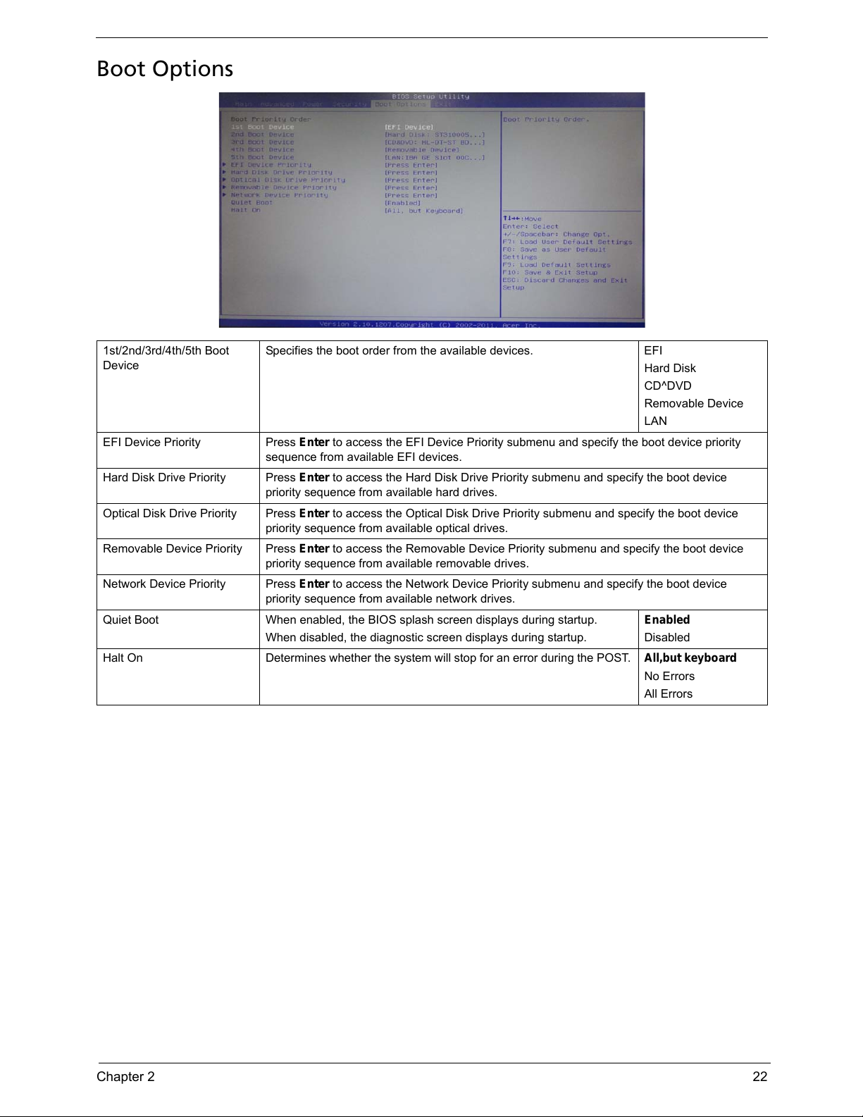
Boot Options
1st/2nd/3rd/4th/5th Boot
Device
Specifies the boot order from the available devices. EFI
Hard Disk
CD^DVD
Removable Device
LAN
EFI Device Priority Press Enter to access the EFI Device Priority submenu and specify the boot device priority
sequence from available EFI devices.
Hard Disk Drive Priority Press Enter to access the Hard Disk Drive Priority submenu and specify the boot device
priority sequence from available hard drives.
Optical Disk Drive Priority Press Enter to access the Optical Disk Drive Priority submenu and specify the boot device
priority sequence from available optical drives.
Removable Device Priority Press Enter to access the Removable Device Priority submenu and specify the boot device
priority sequence from available removable drives.
Network Device Priority Press Enter to access the Network Device Priority submenu and specify the boot device
priority sequence from available network drives.
Quiet Boot When enabled, the BIOS splash screen displays during startup.
When disabled, the diagnostic screen displays during startup.
Enabled
Disabled
Halt On Determines whether the system will stop for an error during the POST. All,but keyboard
No Errors
All Errors
Page 31

23 Chapter 2
Exit
Parameter Description
Save & Exit Setup When you have completed the system configuration changes, select this option to leave the
BIOS Setup Utility and reboot the computer, so the new system configuration parameters can
take effect. Select
Save & Exit Setup from the Exit menu and press Enter.
Discard Changes and Exit
Setup
Select this option to quit the BIOS Setup Utility without making any permanent changes to the
system configuration, and reboot the computer. Select
Discard Changes and Exit Setup
from the Exit menu and press
Enter.
Save Changes
Select this option and press Enter to save all the changes and return to the BIOS Setup Utility.
Discard Changes Use this item enables you to discard any changes that you have made.
Load Default Settings
To set this feature, select
Load Default Settings from the Exit menu and press Enter. Then,
select OK to allow the BIOS to automatically load optimal defaults to the BIOS settings. The
Optimal settings are designed for maximum system performance, but may not work best for all
computer applications.
Save as User Default
Settings
Select this option and press
Enter to save changes that you have made as user defaults.
Load User Default Settings
Select this option and press
Enter to restore user defaults.
Page 32

chapter 3 24
This chapter contains step-by-step procedures on how to disassemble and assembly the desktop computer for
maintenance and troubleshooting.
Disassembly Requirements
To disassemble the computer, you need the following tools:
• Wrist grounding strap and conductive mat for preventing electrostatic discharge
• Flat-blade screwdriver
• Philips screwdriver
• Hex screwdriver
• Plastic flat-blade screwdriver
• Plastic tweezers
NOTE: The screws for the different components vary in size. During the disassembly process, group the
screws with the corresponding components to avoid mismatch when putting back the components.
System Disassembly and Assembly
Chapter 3
Page 33

25 Chapter 3
Pre-disassembly Procedure
Before proceeding with the disassembly procedure, perform the steps listed below:
1. Turn off the system and all the peripherals connected to it.
2. Unplug the power cord from the power outlets.
3. Unplug the power cord from the system.
4. Unplug all peripheral cables from the system.
5. Place the system unit on a flat, stable surface.
Page 34

Chapter 3 26
Removing the Side Panel
1. Remove the two screws located on the rear edge of the side panel.
2. Slide the side panel toward the back of the chassis until the tabs on the cover disengage with the slots on
the chassis.
3. Lift the side panel away from the server and put it aside for reinstallation later.
Page 35

27 Chapter 3
Removing the Heat Sink Fan Assembly
WARNING:The heat sink becomes very hot when the system is on. NEVER touch the heat sink with any metal
or with your hands.
1. Use a long-nosed screwdriver to loosen the four screws on the heat sink, in the order as shown below.
Note:CPU Fan has been highlighted with the yellow circle as above image shows.Please detach the CPU Fan
and follow local regulations for disposal.
2. Lift the heat sink fan assembly away from the mainboard.
Page 36

Chapter 3 28
3. Lay down the heat sink fan assembly, in an upright position, on top of the optical drive, as shown below,
then disconnect the fan cable from the mainboard.
4. Remove the heat sink fan assembly from the chassis then lay it down in an upright position—with the
thermal patch facing upward. Do not let the thermal patch on the heat sink fan assembly touch the work
surface.
5. Use an alcohol pad to wipe off the thermal grease from both the heat sink and the processor.
Page 37

29 Chapter 3
Removing the Processor
IMPORTANT:Before removing a processor from the mainboard, make sure to create a backup file of all
important data.
WARNING:The processor becomes very hot when the system is on. Allow it to cool off first before handling.
1. Release the load lever.
2. Lift the load lever and load plate to the fully open, upright position (2) and (3).
Page 38

Chapter 3 30
3. Pull out the processor from the socket.
IMPORTANT: If you are going to install a new processor, note the arrow on the corner to make sure the
processor is properly oriented over the socket.
Page 39

31 Chapter 3
Removing the TV-Tuner Card
1. Remove the screws that secures the card to the chassis.
2. Gently pull the card to remove it from the mainboard.
Note:Circuit boards >10 cm² has been highlighted with the yellow rectangle as above image shows. Please
detach the Circuit boards and follow local regulations for disposal.
Page 40

Chapter 3 32
Removing the VGA Card
1. Remove the screws that secures the card to the chassis.
2. Gently pull the card to remove it from the mainboard.
Note:Circuit boards >10 cm² has been highlighted with the yellow rectangle as above image shows. Please
detach the Circuit boards and follow local regulations for disposal.
Page 41

33 Chapter 3
Removing the Front Bezel
3. Release the front bezel from the chassis interior.
4. Pull the bezel away from the chassis.
NOTE: The bezel can’t be entirely removed until completed below step.due to the other end of power cable
connecting with motherboard.
Page 42

Chapter 3 34
Removing the Cage of ODD and HDD
1. Disconnect the data and power cables from the rear of the optical drive.
2. Remove the two screws from chassis.
3. Lift the cage up and turn it over.
Page 43

35 Chapter 3
4. Lay down the cage assembly in chassis, as shown below, then disconnect the data and power cables
from the rear of the Hard disk drive.
5. Disconnect the other end of the HDD/ODD data cable from the mainboard.
6. Release the HDD data cables away from Chassis clip.
Page 44

Chapter 3 36
7. Disconnect the power switch cable from the motherboard.
8. Pull the power switch cable from the chassis, then remove the bezel.
Page 45

37 Chapter 3
Removing the Hard Disk Drive
1. Remove the four screws that secure the HDD module to the HDD bracket.
2. Slide the HDD out of the bracket.
Page 46

Chapter 3 38
Removing the Optical Drive
1. Remove the screw from the bracket.
2. Pull the drive out of the drive bay.
Page 47

39 Chapter 3
Removing the Memory Modules
IMPORTANT:Before removing any DIMM from the memory board, make sure to create a backup file of all
important data.
1. Press the holding clips on both sides of the DIMM slot outward to release the DIMM(1).
2. Gently pull the DIMM upward to pull it away from the M/B(2).
Note:Circuit boards >10 cm² has been highlighted with the yellow rectangle as above image shows. Please
detach the Circuit boards and follow local regulations for disposal.
Page 48

Chapter 3 40
Removing the Power Supply
1. Disconnect the 4-pin and 24-pin power supply cables from the mainboard.
2. Remove the screw that secures the power supply to the chassis.
Page 49

41 Chapter 3
3. Remove the three screws that secure the power supply to the rear panel.
4. Lift the power supply module out of the chassis.
Page 50

Chapter 3 42
Removing the Mainboard
1. Disconnect the front USB cable and front audio cable from the mainboard.
2. Release the cable from retention clip,then take out the retention clip.
3. Release these cables away from Chassis clip.
Page 51

43 Chapter 3
4. Remove the four screws that secure the mainboard to the chassis.
Note:Circuit boards >10 cm² has been highlighted with the yellow rectangle as above image shows.
Please detach the Circuit boards and follow local regulations for disposal.
5. Lift the board from the chassis.
Page 52

Chapter 3 44
6. Punching in IO Shield then you can remove it.
7. Remove the RTC battery.
Note:RTC battery has been highlighted with the yellow circle as above image shows.Please detach the RTC
battery and follow local regulations for disposal.
Page 53

45 Chapter 3
Removing the Front I/O&USB and Card Reader Boards
1. Removing the screw from chassis.
2. Pull the front I/O and USB assembly from chassis.
Page 54

Chapter 3 46
3. Remove the card reader board.
a. Remove the two screws that secure the card reader board to the bracket.
b. Pull the card reader board out of the bracket.
Note:Circuit boards >10 cm² has been highlighted with the yellow rectangle as above image shows. Please
detach the Circuit boards and follow local regulations for disposal.
Page 55

47 Chapter 3
4. Remove the front I/O&USB board.
a. Remove the two screws that secure the I/O&USB board to the bracket.
b. Pull the I/O&USB board out of the bracket.
Note:Circuit boards >10 cm² has been highlighted with the yellow rectangle as above image shows. Please
detach the Circuit boards and follow local regulations for disposal.
Page 56

Chapter 3 48
Assembly Requirements
To assemble the computer, you need the following tools:
• Wrist grounding strap and conductive mat for preventing electrostatic discharge
• Flat-blade screwdriver
• Philips screwdriver
• Hex screwdriver
• Plastic flat-blade screwdriver
• Plastic tweezers
NOTE: The screws for the different components vary in size. During the assembly process, group the screws
with the corresponding components to avoid mismatch when putting back the components.
Page 57

49 Chapter 3
Assembly Procedure
Before proceeding with the assembly procedure, perform the steps listed below:
1. Turn off the system and all the peripherals connected to it.
2. Unplug the power cord from the power outlets.
3. Unplug the power cord from the system.
4. Unplug all peripheral cables from the system.
5. Place the system unit on a flat, stable surface.
Page 58

Chapter 3 50
Install the Processor
1. Release the load lever.
2. Lift the load lever and load plate to the fully open,then take out the CPU cover.
3. Put the CPU in the seat and close the load plate and load lever.
NOTE: When you install the processor, note the arrow on the corner to make sure the processor is properly
oriented over the socket.
Page 59

51 Chapter 3
Install the Memory
1. Open the holding clips on both sides of the DIMM slot outward.
2. Press down the memory.
IMPORTANT:pls refer to below installing memory rule.
DIMM1 DIMM2
A
AA
AB
Remark:A and B show different size
of memory, size:A>B
Page 60

Chapter 3 52
Install the Heat Sink Fan Assembly
1. Put the CPU cooler on M/B retention module.
2. Use a long-nosed screwdriver to fix the four screws on the heat sink, in the order as shown below.
3. Connect the cooler cable to the main board.
Page 61

53 Chapter 3
Removing the Side Panel
1. Remove the two screws located on the rear edge of the side panel.
2. Slide the side panel toward the back of the chassis until the tabs on the cover disengage with the slots on
the chassis.
3. Lift the side panel away from the server and put it aside for reinstallation later.
Page 62

Chapter 3 54
Removing the Front Bezel
4. Release the front bezel from the chassis interior.
5. Pull the bezel away from the chassis.
Page 63

55 Chapter 3
Removing the Cage of ODD and HDD
1. Remove the two screws from chassis.
2. Lift the cage up and turn it over.
3. Punching in PCI Shelf slice then you can remove it.
Page 64

Chapter 3 56
Install the Power Supply
1. Install the power supply to chassis.
2. Fix the three screws.
3. Fix another screw.
Page 65

57 Chapter 3
Install the I/O Shielding
1. Install I/O shielding into chassis.
Page 66

Chapter 3 58
Install the Main Board
1. Put M/B in the chassis aligning the M/B I/O connector with I/O shielding.
2. Fix1~ 6 pcs screws into the corresponding hole.
NOTE: Make sure the I/O spring touching M/B after installing.
Page 67

59 Chapter 3
Connect the Cable
1. Install the retention clip to chassis.
2. Take the bezel, shall front panel cable pass through chassis’s hole. as below blue rectangle image show.
3. Connect the front panel cable, front USB cable, and front audio cable to the mainboard. then fix the front
audio cable with the retention clip.
Page 68

Chapter 3 60
4. Connect the ATX 24Pin Power cable and ATX 4Pin Power cable to main board.
Page 69

61 Chapter 3
Install the Optica Drive
1. Push the drive to the drive bay.
2. Fix the screw to the bracket.
Page 70

Chapter 3 62
Install the Hard Disk Drive
1. Slide the HDD to the bracket.
2. Fix the four screws to bracket.
Page 71

63 Chapter 3
Install the Cage of ODD and HDD
1. Connect the other end of the HDD and ODD data cable to the mainboard.
2. Let HDD SATA data cable pass through the two chassis clips.
3. Connect the data and power cables to the rear of the Hard disk drive.
Page 72

Chapter 3 64
4. Install the cage to chassis.
5. Fix the two screws to chassis.
6. Connect the power cables and data cable to the rear of the optical drive.
Page 73

65 Chapter 3
Install the Front Bezel
1. Install the panel onto chassis and then check if it is Installed OK.
Page 74

Chapter 3 66
Install the VGA Card
1. Open the VGA card latch.
2. Install the VGA card to PCIE x16 slot.
Page 75

67 Chapter 3
Install the TV-Tuner Card
1. Press down the TV-Tuner card.
2. Fix the two screws.
Page 76

Chapter 3 68
Install the Side Panel
1. Install the side Panel, then fix two Screws.
Page 77

Chapter 4 69
This chapter provides instructions on how to troubleshoot system hardware problems.
Hardware Diagnostic Procedure
IMPORTANT:The diagnostic tests described in this chapter are only intended to test Acer products. Non-Acer
products, prototype cards, or modified options can give false errors and invalid system
responses.
1. Obtain the failing symptoms in as much detail as possible.
2. Verify the symptoms by attempting to recreate the failure by running the diagnostic tests or repeating
thesame operation.
3. Refer to “Power System check” on page 70 and “Beep Codes” on page 71 to determine which corrective
action to perform.
System Troubleshooting
Chapter 4
Page 78

70 Chapter 4
System Check Procedures
Power System Check
If the system will power on, skip this section. Refer to System External Inspection.
If the system will not power on, do the following:
• Check if the power cable is properly connected to the system and AC source.
• Check if the voltage selector switchis set to the correct voltage setting.
System External Inspection
1. Inspect the LED indicators on the front panel, which can indicate the malfunction.
2. Make sure that air flow is not blocked.
3. Make sure nothing in the system is making contact that could short out power.
4. If the problem is not evident, continue with System Internal Inspection.
System Internal Inspection
1. Turn off the system and all the peripherals connected to it.
2. Unplug the power cord from the power outlets.
3. Unplug the power cord from the system.
4. Unplug all peripheral cables from the system.
5. Place the system unit on a flat, stable surface.
6. Remove the system covers.For instructions on removing system covers, refer to “System Disassembly”
on page 24.
7. Verify that components are properly seated.
8. Verify that all cable connectors inside the system are firmly and correctly attached to their appropriate
connectors.
9. Verify that all components are Acer-qualified and supported.
10. Replace the system covers.
11. Power on the system.
12. If the problem with the system is not evident, you can try viewing the POST messages and BIOS event
logs during the system startup.
Page 79

Chapter 4 71
Beep Codes
Beep codes are used by the BIOS to indicate a serious or fatal error to the end user. Beep codes are used
when an error occurs before the system video has been initialized. Beep codes will be generated by the
system board speaker, commonly referred to as the PC speaker.
AMIBIOS displays the checkpoints in the bottom right corner of the screen during POST. This display method
is limited, since it only displays checkpoints that occur after the video card has been activated.
Not all computers using AMIBIOS enable this feature. In most cases, a checkpoint card is the best tool for
viewing AMIBIOS checkpoints.
Beep Symptom Cause and Description
One short beep System is ready.
System is OK.
Continuous one long beep Memory not installed or memory error.
One long beep and two short beeps then
repeat.
VGA not installed or VGA error.
Graphics card error/not installed, graphics card memory
error or graphics card BIOS checksum error.
One long beep then two short beep BIOS damaged.
BIOS is damaged, BIOS POST jumps to Boot Block to
execute the default procedures.
Two short beeps CMOS damaged.
CMOS checksum error or CMOS battery loss occurs.
Page 80

72 Chapter 4
Checkpoints
A checkpoint is either a byte or word value output to I/O port 80h.The BIOS outputs checkpoints throughout
bootblock and Power-On Self Test (POST) to indicate the task the system is currently executing. Checkpoint
sare very useful in aiding software developers or technicians in debugging problems that occur during the pre-
boot process.
Viewing BIOS checkpoints
Viewing all checkpoints generated by the BIOS requires acheckpoint card, also referred to as a POST card or
POST diagnostic card. These are ISA or PCI add-in cards that show the value of I/O port 80h on a LED
display. Checkpoints may appear on the bottom right corner of the screen during POST. This display method
islimited, since it only displays checkpoints thatoccur after the video card has been activated.
Bootblock Initialization Code Checkpoints
The Bootblock initialization code sets up the chipset,memory, and other components before system memory is
available. The following table describes the type of checkpoints that may occur during the bootblock
initialization portion of the BIOS.
NOTE: Please note that checkpoints may differ between different platforms based on system
configuration.Checkpoints may change due to vendor requirements,system chipset or option ROMs
from add-in PCI devices.
Checkpoint Description
Before D0 If boot block debugger is enabled, CPU cache-as-RAM functionality is enabled at this point.
Stack will be enabled from this point.
D0 Early Boot Strap Processor (BSP) initialization like microcode update, frequency and other
CPU critical initialization. Early chipset initialization is done.
D1 Early super I/O initialization is done including RTC and keyboard controller. Serial port is
enabled at this point if needed for debugging. NMI is disabled. Perform keyboard controller
BAT test. Save power-on CPUID value in scratch CMOS. Go to flat mode with 4GB limit and
GA20 enabled.
D2 Verify the boot block checksum. System will hang here if checksum is bad.
D3 Disable CACHE before memory detection. Execute full memory sizing module. If memory
sizing module not executed, start memory refresh and do memory sizing in Boot block code.
Do additional chipset initialization. Re-enable CACHE. Verify that flat mode is enabled.
D4 Test base 512KB memory. Adjust policies and cache first 8MB. Set stack.
D5 Bootblock code is copied from ROM to lower system memory and control is given to it. BIOS
now executes out of RAM. Copies compressed boot block code to memory in right
segments. Copies BIOS from ROM to RAM for faster access. Performs main BIOS
checksum and updates recovery status accordingly.
D6 Both key sequence and OEM specific method is checked to determine if BIOSrecovery is
forced. Main BIOS checksum is tested. If BIOS recovery is necessary,control flows to
checkpoint E0. See Bootblock Recovery Code Checkpoints sectionfor more information.
D7 Restore CPUID value back into register. The Bootblock-Runtime interface module is moved
to system memory and control is given to it. Determine whether to execute serial flash.
D8 The Runtime module is uncompressed into memory. CPUID information is stored in memory.
D9 Store the Uncompressed pointer for future use in PMM. Copying Main BIOS into memory.
Leaves all RAM below 1MB Read-Write including E000 and F000 shadow areas but closing
SMRAM.
Page 81

Chapter 4 73
DA Restore CPUID value back into register. Give control to BIOS POST (ExecutePOSTKernel).
See POST Code Checkpoints section of document for more information.
DC System is waking from ACPI S3 state.
E1-E8 EC-
EE
OEM memory detection/configuration error. This range is reserved for chipset vendors &
system manufacturers. The error associated with this value may be different from one
platform to the next.
Checkpoint Description
Page 82

74 Chapter 4
Bootblock Recovery Code Checkpoints
The Bootblock recovery code gets control when the BIOS determines that a BIOS recovery needs to occur
because the user has forced the update or the BIOS checksum is corrupt. The following table describes the
type of checkpoints that may occur during the Bootblock recovery portion of the BIOS.
NOTE: Checkpoints may differ between different platforms based on system configuration. Checkpoints
maychange due to vendor requirements, system chipset or option ROMs from add-in PCI devices.
Checkpoint Description
E0 Initialize the floppy controller in the super I/O. Some interrupt vectors are initialized. DMA
controller is initialized. 8259 interrupt controller is initialized. L1 cache is enabled.
E9 Set up floppy controller and data. Attempt to read from floppy.
EA Enable ATAPI hardware. Attempt to read from ARMD and ATAPI CDROM.
EB Disable ATAPI hardware. Jump back to checkpoint E9.
EF Read error occurred on media. Jump back to checkpoint EB.
F0 Search for pre-defined recovery file name in root directory.
F1 Recovery file not found.
F2 Start reading FAT table and analyze FAT to find the clusters occupied by the recovery file.
F3 Start reading the recovery file cluster by cluster.
F5 Disable L1 cache.
FA Check the validity of the recovery file configuration to the current configuration of the flash
part.
FB Make flash write enabled through chipset and OEM specific method. Detect proper flash
part. Verify that the found flash part size equals the recovery file size.
F4 The recovery file size does not equal the found flash part size.
FC Erase the flash part
FD Program the flash part.
FF The flash has been updated successfully. Make flash write disabled. Disable ATAPI
hardware. Restore CPUID value back into register. Give control to F000 ROM at
F000:FFF0h.
Page 83

Chapter 4 75
BIOS Recovery
AMIBIOS supports a "recovery flash" mode, which can be used to flash update a BIOS from the boot block.
This is used to update a BIOS image without the need to boot to an operating system. The following is the
process that user should follow to flash BIOS ROM.
1. Put the AMIBoot.ROM to a bootable USB flash drive(Disk on Key, DOK).
2. Install the DOK to the system.
3. Press power button to boot the system and then press Ctrl + Home.
4. The BIOS recovery function will be executed.
5. After BIOS is updated completely, the system will auto reboot.
6. Please enter the setup menu to load default after system reboot.
Page 84

Chapter 5 76
M/B Placement
Jumper and Connector Information
Chapter 5
Page 85

77 Chapter 5
No Label Description No Label Description
1 CPU LGA1155 socket for
Intel® Sandy Bridge
processor family
11 F_PANEL Front panel switch/
LED header
2 SYS_FAN System cooling fan
connector
12 CLR_CMOS Clear CMOS jumper
3 CPU_FAN CPU cooling fan
connector
13 BZ1 Buzzer
4 DIMM1~2 240-Pin DDR3
SDRAM
slots(Channel A:
DIMM2 Channel B:
DIMM1)
14 ME_DISABLE ME Disable Header
5 GPIO1 General Purpose I/O
Signal 1
15 SPDIF_OUT SPDIF out header
6 GPIO2 General Purpose I/O
Signal 2
16 F_AUDIO Front panel audio
header
7 ATX_POWER Standard 24-pin ATX
power connector
17 PCIE 16X PCI Express x16 slot
8 F_USB3 Front panel USB
header (card reader)
18 PCIE1X_1 PCI Express x1 slot
9 F_USB2 Front panel USB
headers
19 ATX_12V Auxiliary 4-pin power
connector
10 SATA1~2 Serial ATA 3.0Gb/s
connectors (Black
color)
Page 86

Chapter 5 78
Jumper Setting
The section explains how to set jumper for correct configuration of the mainboard.
Setting Jumper
Use the motherboard jumpers to set system configuration options. Jumpers with more Than one pin are
numbered. When setting the jumpers, ensure that the jumper caps are Placed on the correct pins.
The illustrations show a 2-pin jumper. Whenthe jumper cap is placed on both pins, thejumper is SHORT. If you
remove the jumpercap, or place the jumper cap on just one pin,the jumper is OPEN.
This illustration shows a 3-pin jumper. Pins1 and 2 are SHORT.
Checking Jumper Settings
The following illustration shows the location of the motherboard jumpers. Pin 1 is labeled.
Page 87

79 Chapter 5
Jumper Settings
Jumper
Type Description
Setting (default)
CLR_CMOS
3-pin CLEAR CMOS
1-2: NORMAL
2-3: CLEAR
Before clearing the
CMOS, make sure to
turn the system off.
CLR_CMOS
ME_DISABLE 3-pin Disable ME
1-2: NORMAL
2-3: ME disable
Page 88

Chapter 5 80
Checking Connector
Connecting Optional Devices
F_AUDIO: Front Panel Audio heade
This header allows the user to install auxiliary front-oriented microphone and line-out ports for easier access.
GPIO1~2: Button recovery jumper
Pin Signal Name Pin Signal Name
1PORT-F_L 2AUGND
3 PORT-F_R 4 AUD_FP_DET
5 PORT-E_R 6 F_R_A
7 SenseB 8 NC
9 PORT -E_L 10 F_L_A
Pin Signal Name
1GP36(GP16)
2GND
Page 89

81 Chapter 5
SATA1: Serial ATA connectors
These connectors are used to support the Serial ATA 3Gb/s devices, simpler disk drivecabling and easier PC
assembly. It eliminates limitations of the current Parallel ATAinterface. But maintains register compatibility and
sofeware compatibility with PrallelATA.
F_USB2~3: Front Panel USB headers
The motherboard has four USB 2.0 headers supporting four USB 2.0 ports. Addition-ally, some computer
cases have USB ports at the front of the case. If you have thiskind of case, use auxiliary USB connector to
connect the front-mounted ports to themotherboard.
NOTE: Please make sure that the USB cable has the same pin assignment asindicated above. A different pin
assignment may cause damage or systemhang-up.
SPDIFO: SPDIF out header
This is an optional header that provides an SPDIFO (Sony/Philips Digital Interface)output to digital multimedia
device through optical fiber or coaxial connector.
Pin Signal Name Pin Signal Name
1Ground 2TX+
3 TX- 4 Ground
5 RX- 6 RX+
7 Ground
Pin Signal Name Function
1 USBPWR Front Panel USB Power
2 USBPWR Front Panel USB Power
3 DATA0- USB Port 0 Negative Signal
4 DATA1- USB Port 1 Negative Signal
5 DATA0+ USB Port 0 Positive Signal
6 DATA1+ USB Port 1 Positive Signa
7 GND Ground
8 GND Ground
9 NC Not connected
10 USB DET USB DET
Pin Signal Name
1VCC
2 KEY
3 SPDIFOUT
4GND
Page 90

Chapter 5 82
Connecting Case Components
CPU_FAN: CPU cooling FAN Power Connector
SYS_FAN: System Cooling FAN Power Connector
Pin Signal Name Function
1 GND System Ground
2 +12V Power +12V
3 Sense Sensor
4 Control CPU FAN control
Pin Signal Name Function
1 GND System Ground
2 +12V Power +12V
3 Sense Sensor
4 CONTROL CONTROL
Page 91

83 Chapter 5
ATX_ POWER: ATX 24-pin Power Connector
ATX12V: ATX 12V Power Connector
Pin Signal Name Pin Signal Name
1 +3.3V 13 +3.3V
2 +3.3V 14 -12V
3COM 15COM
4 +5V 16 PS_ON
5COM 17COM
6+5V 18COM
7COM 19COM
8 PWR OK 20 -5V
9+5VSB 21+5V
10 +12V 22 +5V
11 +12V 23 +5V
12 +3.3V 24 COM
Pin Signal Name
1 Ground
2 Ground
3+12V
4+12V
Page 92

Chapter 5 84
Front Panel Header
The front panel header (F_PANEL) provides a standard set of switch and LED headers commonly found on
ATX or micro-ATX cases. Refer to the table below for information:
Pin Signal Function Pin Signal Function
1 VCC 5V 2 GLED0 MSG LED
3 HDD_LED Hard disk LED 4 GLED1 MSG LED
5 GND Ground 6 PWRSW POWER SWITCh
7 HWRST_L Reset 8 GND Ground
9 F_PANEL_DET FRONT PANEL
DETECT
10 KEY NO PIN
11 NC Reserved 12 VCC 5V
13 NC Reserved 14 F_PANEL_LED FRONT PANEL
LED
Page 93

chapter 6 85
This chapter offers the FRU (Field Replaceable Unit) list in global configuration of the Aspire X3990 desktop
computer. Refer to this chapter whenever ordering the parts to repair or for RMA (Return Merchandise
Authorization).
NOTES:
• When ordering FRU parts, check the most up-to-date information available on your regional web
or channel. For whatever reasons a part number is changed, it will NOT be noted on the printed
Service Guide. For Acer authorized service providers, your Acer office may have a different part
number code from those given in the FRU list of this printed Service Guide. You MUST use the
local FRU list provided by your regional Acer office to order FRU parts for service.
• To scrap or to return the defective parts, follow the local government ordinance or regulations on
how to dispose it properly, or follow the rules set by your regional Acer office on how to return it.
• This document will be updated as more information about the FRU list becomes available.
FRU (Field Replaceable Unit) List
Chapter 6
Page 94

86 Chapter 6
Aspire X3990 Exploded Diagram
NOTE: This section will be updated when more information becomes available.
Page 95

Chapter 6 87
ITEM NAME Q’TY ITEM NAME Q’TY
1 Chassis-Bottom 1 17 Latch-ODD-Button 1
2 IO Sheilding 1 18 ODD-Shielding 1
3 Mother Board 1 19 ODD-Door 1
4 U-Chassis 1 20 ODD-Button 1
5 HDD-Bracket 1 21 F-IO Door 1
6 HDD 1 22 F-IO Mylar 1
7 Side Plate 1 23 Spring-IO-Door 1
8 ODD-Bracket-Link 1 24 Front-Bezel 1
9 Top-Cover 1 25 Spring-ODD-Door1 1
10 HDD-Lens 1 26 Spring-ODD-Door2 1
11 Power-Switch 1 27 F-IO 1
12 Deco-Belt 1 28 ODD 1
13 Spring-Button 1 29 ODD-Bracket 1
14 Power Button 1 30 Power Supply 1
15 LED 1 31 Rubber 2
16 Acer Logo 1
Page 96

88 Chapter 6
Aspire X3990 FRU List
Category Description Part Number
Exploded
Diagram Item
MB Kit
MB Kit AX1930 Intel H61 Intel 82579V GbE
Proprietary W/O 1394 LF DDRIII 2 DIMM W/ EUP
MB.SGA07.002 3
Chassis
Hon Hai Chassis xSFF HX097G w/ front
USB4+1port for Aspire AX360 Bezel supports I/O
shielding
HS.13100.214 N/A
Hon Hai Chassis xSFF HX097H w/o CR, w/ front
USB4+1port for Aspire AX361 Bezel supports I/O
shielding
HS.13100.215
Bezel
Hon Hai Aspire Bezel AX361 w/o CR, w/ USB
4+1port bezel w/HX097H chassis
PZ.11900.247 N/A
Hon Hai Aspire Bezel AX362 w/ USB 2+1port
bezel w/HX097G chassis
PZ.11900.281
CPU
"CPU Intel Core i7 2600 3.4G 8M 1333 95W K-0
LGA-1155, Sandy Bridge"
KC.26001.CI7 N/A
"CPU Intel Core i5 2500 3.3G 6M 1333 95W K-0 ,
LGA1155, Sandy Bridge"
KC.25001.CI5
"CPU Intel Core i5 2400 3.1G 6M 1333 95W K-0
LGA1155, Sandy Bridge "
KC.24001.CI5
"CPU Intel Core i5 2300 2.8G 6M 1333 95W D-2
LGA1155, Sandy Bridge, Quad Core"
KC.23001.CI5
Page 97

Chapter 6 89
"Core i3-2120 (3.30G 3M DDR3 1333) , D2 , 65W" KC.21201.CI3
"Core i3-2100 (3.10G 3M DDR3 1333) , D2 , 65W" KC.21001.CI3
CPU Intel Core i3 2105 LGA 3.1G 3M 1333 1155
65W Dual Core
KC.10501.CI3
"CPU Intel Core i5 2310 LGA 6M 1155 95W 2.9G,
Quad Core"
KC.23101.CI5
Memory
GU502203EP0201 LF 128*8 0.065um KN.1GB0H.015 N/A
M378B2873FHS-CH9 128*8 46nm KN.1GB0B.036
75.073C1.G02 0.065um KN.1GB01.031
ACR128X64D3U1333C9 LF 128*8 0.07um KN.1GB07.002
AD63I1A0823EU KN.1GB0C.010
GU512303EP0202 LF 128*8 0.065um KN.2GB0H.009
M378B5773CH0-CH9 256*8 46nm KN.2GB0B.029
NT2GC64B88B0NF-CG 256*8 50nm KN.2GB03.022
ACR256X64D3U1333C9 LF 128*8 0.07um KN.2GB07.002
AD63I1B1624EU KN.2GB0C.007
M378B5273BH1-CH9 LF 256*8 0.055um KN.4GB0B.006
M378B5273DH0-CH9 KN.4GB0B.014
NT4GC64B8HB0NF-CG KN.4GB03.006
MT16JTF51264AZ-1G4D1 KN.4GB04.002
HDD
"HDD HGST 3.5"" 7200rpm 160GB
HDS721016CLA382 ( Jupiter) SATA II 8MB LF F/
W:3EA"
KH.16007.027 6
"HDD HGST 3.5"" 7200rpm 320GB
HDS721032CLA362 (Jupiter) SATA II 16MB LF F/
W:3EA"
KH.32007.011
"HDD HGST 3.5"" 7200rpm 500GB
HDS721050CLA362 (Jupiter) SATA II 16MB LF F/
W:3EA"
KH.50007.012
"HDD HGST 3.5"" 7200rpm 1000GB
HDS721010CLA332 (Jupiter) SATA II 32MB LF F/
W:3EA"
KH.01K07.003
"HDD SEAGATE 3.5"" 7200rpm 160GB
ST3160313AS(Pharaoh 6G) SATA III 16MB LF F/
W:JC45"
TBD
"HDD SEAGATE 3.5"" 7200rpm 320GB
ST3320413AS(Pharaoh 6G) SATA III 16MB LF F/
W:JC45"
KH.32001.022
Category Description Part Number
Exploded
Diagram Item
Page 98

90 Chapter 6
"HDD SEAGATE 3.5"" 7200rpm 500GB
ST3500413AS(Pharaoh 6G) SATA III 16MB LF F/
W:JC45"
KH.50001.022
"HDD SEAGATE 3.5"" 7200rpm 1000GB
ST31000524AS(Pharaoh 6G) SATA III 32MB LF F/
W:JC45"
KH.01K01.016
"HDD SEAGATE 3.5"" 7200rpm 1500GB
ST31500341AS(Brinks) SATA II 32MB LF F/
W:CC4H"
KH.15K01.002
"HDD WD 3.5"" 7200rpm 320GB WD3200AAKX-
221CA0(XL500-1D 6G) SATA III 16MB LF F/
W:15.01H15"
KH.32008.023
"HDD WD 3.5"" 7200rpm 500GB WD5000AAKX-
221CA0(XL500-1D 6G) SATA III 16MB LF F/
W:15.01H15"
KH.50008.022
"HDD WD 3.5"" 7200rpm 1000GB WD10EALX-
229BA0(XL500-2D 6G) SATA III 32MB LF F/
W:15.01H15"
KH.01K08.012
"HDD WD 3.5"" 5400rpm 1000GB WD10EADX-
22TDHB0 ( GP500 ) SATA III 32MB LF F/
W:77.04D77"
KH.01K08.013
"HDD WD 3.5"" 5400rpm 1000GB WD10EARS-
22Y5B1 (GP500M-2D 4K sector) SATA II LF F/
W:80.00A80"
KH.01K08.008
"HDD WD 3.5"" 5400rpm 1500GB WD15EARS-
22MVWB0 (GP667-3D) SATA II 64MB LF F/
W:50.0AB50"
KH.15K08.003
"HDD WD 3.5"" 5400rpm 2000GB WD20EARS-
22MVWB0(GP667-3D) SATA II LF F/W:50.0AB50"
KH.02K08.006
"HDD WD 3.5"" 5400rpm 1000GB WD10EARS-
22Y5B1 (GP500M-2D 4K sector) SATA II LF F/
W:80.00A80"
KH.01K08.008
ODD
ODD HLDS DVD-ROM HH DL 16X DH40N LF+HF
Black Bezel (HF+Win7) SATA
KV.0160D.017 28
ODD PLDS DVD-ROM HH DL 16X DH-16D5SH
LF+HF Black Bezel SATA w/Win7
KV.0160F.002
ODD HLDS Super-Multi DRIVE HH DL 16X
GH60N LF+HF Black Bezel SATA HF+Win7
KU.0160D.054
ODD PLDS Super-Multi DRIVE HH DL 16X DH-
16ABSH LF Black Bezel (HF+Win7) SATA
KU.0160F.011
ODD HLDS BD COMBO HH 6X CH20N Black
Bezel SATA HF + Win7
KO.0060D.005
ODD HLDS BD RW HH 8X BH38N LF+HF Black
Bezel SATA (w/ Bus Encryption )
KU.0080D.061
ODD PLDS BD RW HH DL 8X DH-8B2SH LF+HF
Black Bezel SATA (w/ Bus Encryption)
KU.0080F.018
Category Description Part Number
Exploded
Diagram Item
Page 99

Chapter 6 91
ODD HLDS BD RW HH 6X BH30N Black Bezel
SATA HF +Win7
KU.0060D.004
ODD PLDS BD RW HH DL 6X DH-6B2SH LF+HF
Black Bezel SATA (Win7+HF)
KU.0060F.001
VGA
288-5N162-A01AC GT435M 2GB sDDR3 128bit
Samsung DVI+HDMI LP Bracket
VG.PCPT4.354 N/A
288-5N162-B01AC GT435M 2GB sDDR3 128bit
Hynix DVI + HDMI LP Bracket
VG.PCPT4.352
288-2N162-B01AC GT420 2GB 128 bit DVI-
I+HDMI LP Hynix
VG.PCPT4.261
288-2N162-A01AC GT420 2GB SDDR3 128bit
Samsung DVI+HDMI LP
VG.PCPT4.262
288-1N162-A01AC GT420 1GB 128bit DVI-
I+HDMI LP Samsung
VG.PCPT4.211
288-1N162-B01AC GT420 1GB 128bit DVI-
I+HDMI LP Hynix
VG.PCPT4.212
288-5E142-A01AC HD6570 1GB DDR3 128BITS
DVI-I (SL) HDMI SAMSUNG LP BRACKET
VG.APC65.702
288-5N158-A20AC 405 1GB 64bits DDR3 DVI +
DP Samsung LP
VG.PCPT4.004
288-5N158-B20AC 405 1GB 64bits DDR3 DVI +
DP Hynix LP
VG.PCPT4.006
288-5N141-A01AC 405 (GT216) 512MB 64bits
DDR3 DVI + HDMI Samsung LP
VG.PCPT4.002
89D386-469024 405 512MB 64bits DDR3 DVI +
HDMI Hynix LP
VG.ECS40.5L1
288-5E153-A00AC HD6450 1GB SDDR3 64bits
DVI-I + HDMI SAMSUNG (LP)
VG.APC64.521
288-1E180-A00AC HD6450 512MB SDDR3 64bits
DVI-I + HDMI SAMSUNG (LP)
VG.APC64.502
288-7N162-A01AC GT530 2GB 128bit DDR3 DVI
+ HDMI SAMSUNG LP
VG.PCPT5.302
288-7N162-B01AC GT530 2GB 128bit DDR3 DVI
+ HDMI HYNIX LP
VG.PCPT5.304
TV Tuner Card
Avermedia H753-D TV Tuner Card PCIe Hybrid
DVB-T, S/W Encoder, LP bracket
TU.10500.073 N/A
Avermedia H753-A TV Tuner Card PCIe Hybrid
ATSC, S/W Encoder, LP bracket
TU.10500.075
Avermedia H753-C TV Tuner Card PCIe Hybrid
DMB-TH, S/W Encoder, LP
TU.10500.079
Avermedia H751-D TV Tuner Card PCIe Hybrid
DVB-T, S/W Encoder, LP
TU.10500.049
Category Description Part Number
Exploded
Diagram Item
Page 100

92 Chapter 6
Modem Card
D-1156E#/A10A (Low-profile), Modem PCI-Ex1
card, LSI Universal Modem (PCI-E) 56K V.92 -
Concorde (C40)
FX.10100.003 N/A
VD56UL, Modem USB dongle 56K modem W/O
brand logo, LSI SV92PPU2
FX.10100.023
Wireless LAN Card
WU71RL WLAN USB dongle 802.11b/g/n 1T x 1R,
Ralink RT3070F
NI.10200.023 N/A
WN7601R, Ralink RT3090, 802.11b/g/n 1x1
WLAN PCI-E x1 card (Low-profile)
NI.10200.038
USB 3.0 Add-on card
RA351-1, NEC μPD720200, USB 3.0 PCI-Ex1
card, 2 extermal ports, 1 PATA 4-pin power
connector, 50mm height PCB, Low-profile bracket
+ 470mm power Y-cable (1SATA to 1SATA +
1PATA )
PA.14000.043 N/A
Card Reader
9-in-1 CR Alcor AU6476, 420mm USB cable, for
X3, NS
CR.10400.083 N/A
Power Supply
Non-PFC 220W (8.5L) EuP PY.2200B.009 30
Non-PFC 220W (8.5L) EuP PY.22009.009
PFC 220W (8.5L) EuP PY.2200B.010
PFC 220W (8.5L) EuP PY.22009.010
FR 220W (8.5L) EuP 82+ PY.2200B.011
FR 220W (8.5L) EuP 82+ PY.22009.011
Non-PFC 220W (8.5L) EuP PY.2200F.004
PFC 220W (8.5L) EuP PY.2200F.005
Category Description Part Number
Exploded
Diagram Item
 Loading...