

Page 1

Table of Contents
Chapter 1 System Introduction 1
Features . . . . . . . . . . . . . . . . . . . . . . . . . . . . . . . . . . . . . . . . . . . . . . . . . . . . . . . . . . . .1
System Block Diagram . . . . . . . . . . . . . . . . . . . . . . . . . . . . . . . . . . . . . . . . . . . . . . . . .3
Board Layout . . . . . . . . . . . . . . . . . . . . . . . . . . . . . . . . . . . . . . . . . . . . . . . . . . . . . . . .4
Top View . . . . . . . . . . . . . . . . . . . . . . . . . . . . . . . . . . . . . . . . . . . . . . . . . . . . . . . .4
Bottom View . . . . . . . . . . . . . . . . . . . . . . . . . . . . . . . . . . . . . . . . . . . . . . . . . . . . .5
Panel . . . . . . . . . . . . . . . . . . . . . . . . . . . . . . . . . . . . . . . . . . . . . . . . . . . . . . . . . . . . . . .6
Front Panel . . . . . . . . . . . . . . . . . . . . . . . . . . . . . . . . . . . . . . . . . . . . . . . . . . . . . .6
Closed front viewLeft Panel . . . . . . . . . . . . . . . . . . . . . . . . . . . . . . . . . . . . . . . . .7
Left view . . . . . . . . . . . . . . . . . . . . . . . . . . . . . . . . . . . . . . . . . . . . . . . . . . . . . . . .7
Right Panel . . . . . . . . . . . . . . . . . . . . . . . . . . . . . . . . . . . . . . . . . . . . . . . . . . . . . .8
Rear Panel . . . . . . . . . . . . . . . . . . . . . . . . . . . . . . . . . . . . . . . . . . . . . . . . . . . . . .9
Bottom Panel . . . . . . . . . . . . . . . . . . . . . . . . . . . . . . . . . . . . . . . . . . . . . . . . . . .10
Indicators . . . . . . . . . . . . . . . . . . . . . . . . . . . . . . . . . . . . . . . . . . . . . . . . . . . . . . . . . .11
Using the keyboard . . . . . . . . . . . . . . . . . . . . . . . . . . . . . . . . . . . . . . . . . . . . . . . . . . .12
Lock keys . . . . . . . . . . . . . . . . . . . . . . . . . . . . . . . . . . . . . . . . . . . . . . . . . . . . . .12
Embedded numeric keypad . . . . . . . . . . . . . . . . . . . . . . . . . . . . . . . . . . . . . . . .12
Windows keys . . . . . . . . . . . . . . . . . . . . . . . . . . . . . . . . . . . . . . . . . . . . . . . . . . .13
Hot Keys . . . . . . . . . . . . . . . . . . . . . . . . . . . . . . . . . . . . . . . . . . . . . . . . . . . . . . .14
The Euro symbol . . . . . . . . . . . . . . . . . . . . . . . . . . . . . . . . . . . . . . . . . . . . . . . . .15
Launch Keys . . . . . . . . . . . . . . . . . . . . . . . . . . . . . . . . . . . . . . . . . . . . . . . . . . . .15
Touchpad . . . . . . . . . . . . . . . . . . . . . . . . . . . . . . . . . . . . . . . . . . . . . . . . . . . . . . . . . .17
Hardware Specifications and Configurations . . . . . . . . . . . . . . . . . . . . . . . . . . . . . . .19
Chapter 2 System Utilities 30
BIOS Setup Utility . . . . . . . . . . . . . . . . . . . . . . . . . . . . . . . . . . . . . . . . . . . . . . . . . . . .30
Navigating the BIOS Utility . . . . . . . . . . . . . . . . . . . . . . . . . . . . . . . . . . . . . . . . .30
Main . . . . . . . . . . . . . . . . . . . . . . . . . . . . . . . . . . . . . . . . . . . . . . . . . . . . . . . . . .31
Advanced . . . . . . . . . . . . . . . . . . . . . . . . . . . . . . . . . . . . . . . . . . . . . . . . . . . . . .32
Security . . . . . . . . . . . . . . . . . . . . . . . . . . . . . . . . . . . . . . . . . . . . . . . . . . . . . . . .34
Boot . . . . . . . . . . . . . . . . . . . . . . . . . . . . . . . . . . . . . . . . . . . . . . . . . . . . . . . . . . .35
Exit . . . . . . . . . . . . . . . . . . . . . . . . . . . . . . . . . . . . . . . . . . . . . . . . . . . . . . . . . . .36
BIOS Flash Utility . . . . . . . . . . . . . . . . . . . . . . . . . . . . . . . . . . . . . . . . . . . . . . . . . . . .37
Remove BIOS and HDD Password Utility . . . . . . . . . . . . . . . . . . . . . . . . . . . . . . . . .38
Chapter 3 Machine Disassembly and Replacement 40
General Information . . . . . . . . . . . . . . . . . . . . . . . . . . . . . . . . . . . . . . . . . . . . . . . . . .41
Before You Begin . . . . . . . . . . . . . . . . . . . . . . . . . . . . . . . . . . . . . . . . . . . . . . . .41
Disassembly Procedure Flowchart . . . . . . . . . . . . . . . . . . . . . . . . . . . . . . . . . . . . . . .42
Removing the Battery . . . . . . . . . . . . . . . . . . . . . . . . . . . . . . . . . . . . . . . . . . . . . . . . .44
Removing the Hard Disc Drive Module . . . . . . . . . . . . . . . . . . . . . . . . . . . . . . . . . . . .44
Disassembling the Hard Disc Drive Module . . . . . . . . . . . . . . . . . . . . . . . . . . . .44
Removing the Optical Disc Drive Module . . . . . . . . . . . . . . . . . . . . . . . . . . . . . . . . . .45
Disassembling the Optical Disc Drive Module . . . . . . . . . . . . . . . . . . . . . . . . . .45
Removing the Memory . . . . . . . . . . . . . . . . . . . . . . . . . . . . . . . . . . . . . . . . . . . . . . . .45
Removing the LCD Module . . . . . . . . . . . . . . . . . . . . . . . . . . . . . . . . . . . . . . . . . . . . .47
Removing the Middle Cover . . . . . . . . . . . . . . . . . . . . . . . . . . . . . . . . . . . . . . . .47
Removing the Keyboard . . . . . . . . . . . . . . . . . . . . . . . . . . . . . . . . . . . . . . . . . . .47
Removing the Fan, the CPU Thermal Module and the CPU . . . . . . . . . . . . . . .47
Removing the Wireless LAN Card . . . . . . . . . . . . . . . . . . . . . . . . . . . . . . . . . . .48
Removing the LCD Module . . . . . . . . . . . . . . . . . . . . . . . . . . . . . . . . . . . . . . . . .49
Disassembling the LCD Module . . . . . . . . . . . . . . . . . . . . . . . . . . . . . . . . . . . . . . . . .50
Removing the LCD Bezel . . . . . . . . . . . . . . . . . . . . . . . . . . . . . . . . . . . . . . . . . .50
Disassembling the Main Unit . . . . . . . . . . . . . . . . . . . . . . . . . . . . . . . . . . . . . . . . . . .52
1
Page 2

Table of Contents
Removing the Upper Case Assembly . . . . . . . . . . . . . . . . . . . . . . . . . . . . . . . . .52
Removing the Power Board . . . . . . . . . . . . . . . . . . . . . . . . . . . . . . . . . . . . . . . .52
Removing the Touchpad Bracket, the Touchpad Board and the Touchpad . . . .53
Removing the Speaker Set . . . . . . . . . . . . . . . . . . . . . . . . . . . . . . . . . . . . . . . . .54
Removing the SW DJ Board Assembly . . . . . . . . . . . . . . . . . . . . . . . . . . . . . . .54
Removing the Audio Board . . . . . . . . . . . . . . . . . . . . . . . . . . . . . . . . . . . . . . . . .55
Removing the VGA Thermal Module . . . . . . . . . . . . . . . . . . . . . . . . . . . . . . . . .55
Removing the Modem Board . . . . . . . . . . . . . . . . . . . . . . . . . . . . . . . . . . . . . . .56
Removing the Main Board . . . . . . . . . . . . . . . . . . . . . . . . . . . . . . . . . . . . . . . . .56
Removing the Control Board . . . . . . . . . . . . . . . . . . . . . . . . . . . . . . . . . . . . . . . .57
Chapter 4 Troubleshooting 60
System Check Procedures . . . . . . . . . . . . . . . . . . . . . . . . . . . . . . . . . . . . . . . . . . . . .61
External Diskette Drive Check . . . . . . . . . . . . . . . . . . . . . . . . . . . . . . . . . . . . . .61
External CD-ROM/DVD-ROM Drive Check . . . . . . . . . . . . . . . . . . . . . . . . . . . .61
Keyboard or Auxiliary Input Device Check . . . . . . . . . . . . . . . . . . . . . . . . . . . . .61
Memory Check . . . . . . . . . . . . . . . . . . . . . . . . . . . . . . . . . . . . . . . . . . . . . . . . . .62
Power System Check . . . . . . . . . . . . . . . . . . . . . . . . . . . . . . . . . . . . . . . . . . . . .62
Touchpad Check . . . . . . . . . . . . . . . . . . . . . . . . . . . . . . . . . . . . . . . . . . . . . . . . .64
Display Check . . . . . . . . . . . . . . . . . . . . . . . . . . . . . . . . . . . . . . . . . . . . . . . . . . .64
Sound Check . . . . . . . . . . . . . . . . . . . . . . . . . . . . . . . . . . . . . . . . . . . . . . . . . . .65
Insyde MobilePro BIOS POST Beep Code and POST Messages . . . . . . . . . . . . . . .66
Insyde MobilePro BIOS POST Codes . . . . . . . . . . . . . . . . . . . . . . . . . . . . . . . . . . . .72
Index of Symptom-to-FRU Error Message . . . . . . . . . . . . . . . . . . . . . . . . . . . . . . . . .76
Intermittent Problems . . . . . . . . . . . . . . . . . . . . . . . . . . . . . . . . . . . . . . . . . . . . . . . . .79
Undetermined Problems . . . . . . . . . . . . . . . . . . . . . . . . . . . . . . . . . . . . . . . . . . . . . . .80
Chapter 5 Jumper and Connector Locations 82
Top View . . . . . . . . . . . . . . . . . . . . . . . . . . . . . . . . . . . . . . . . . . . . . . . . . . . . . . . . . . .82
Bottom View . . . . . . . . . . . . . . . . . . . . . . . . . . . . . . . . . . . . . . . . . . . . . . . . . . . . . . . .83
Chapter 6 FRU (Field Replaceable Unit) List 84
Aspire 9100 Exploded Diagram . . . . . . . . . . . . . . . . . . . . . . . . . . . . . . . . . . . . . . . . .85
Appendix A Model Definition and Configuration 95
Aspire 9100 Series . . . . . . . . . . . . . . . . . . . . . . . . . . . . . . . . . . . . . . . . . . . . . . . . . . .95
Appendix B Test Compatible Components 96
Microsoft®Windows® XP Environment Test 97
Appendix C Online Support Information 100
2
Page 3

Aspire 9100 Series
Service Guide
Service guide files and updates are available
on the ACER/CSD web; for more information,
please refer to http://csd.acer.com.tw
PRINTED IN TAIWAN
Page 4

Revision History
Please refer to the table below for the updates made on Aspire 9100 service guide.
Date Chapter Updates
4
Page 5

Copyright
Copyright © 2005 by Acer Incorporated. All rights reserved. No part of this publication may be reproduced,
transmitted, transcribed, stored in a retrieval system, or translated into any language or computer language, in
any form or by any means, electronic, mechanical, magnetic, optical, chemical, manual or otherwise, without
the prior written permission of Acer Incorporated.
Disclaimer
The information in this guide is subject to change without notice.
Acer Incorporated makes no representations or warranties, either expressed or implied, with respect to the
contents hereof and specifically disclaims any warranties of merchantability or fitness for any particular
purpose. Any Acer Incorporated software described in this manual is sold or licensed "as is". Should the
programs prove defective following their purchase, the buyer (and not Acer Incorporated, its distributor, or its
dealer) assumes the entire cost of all necessary servicing, repair, and any incidental or consequential
damages resulting from any defect in the software.
Acer is a registered trademark of Acer Corporation.
Intel is a registered trademark of Intel Corporation.
Pentium and Pentium II/III are trademarks of Intel Corporation.
Other brand and product names are trademarks and/or registered trademarks of their respective holders.
5
Page 6
Conventions
The following conventions are used in this manual:
SCREEN MESSAGES Denotes actual messages that appear
on screen.
NOTE Gives bits and pieces of additional
information related to the current
topic.
WARNING Alerts you to any damage that might
result from doing or not doing specific
actions.
CAUTION Gives precautionary measures to
avoid possible hardware or software
problems.
IMPORTANT Reminds you to do specific actions
relevant to the accomplishment of
procedures.
6
Page 7

Preface
Before using this information and the product it supports, please read the following general information.
1. This Service Guide provides you with all technical information relating to the BASIC CONFIGURATION
decided for Acer's "global" product offering. To better fit local market requirements and enhance product
competitiveness, your regional office MAY have decided to extend the functionality of a machine (e.g.
add-on card, modem, or extra memory capability). These LOCALIZED FEATURES will NOT be covered
in this generic service guide. In such cases, please contact your regional offices or the responsible
personnel/channel to provide you with further technical details.
2. Please note WHEN ORDERING FRU PARTS, that you should check the most up-to-date information
available on your regional web or channel. If, for whatever reason, a part number change is made, it will
not be noted in the printed Service Guide. For ACER-AUTHORIZED SERVICE PROVIDERS, your Acer
office may have a DIFFERENT part number code to those given in the FRU list of this printed Service
Guide. You MUST use the list provided by your regional Acer office to order FRU parts for repair and
service of customer machines.
7
Page 8

System Introduction
Features
This computer was designed with the user in mind. Here are just a few of its many features:
Microprocessor
T Intel
Memory
T 256 MB of DDR 333 SDRAM standard, upgradeable to 2 GB with dual so DIMM modules
T 512 KB flash ROM BIOS
Data storage
T One 60 GB and above E-IDE hard disk (2.5”, 9.5mm, UltraDMA-100)
T One internal optical drive
T 3-in-1 MS/SM/SD card reader
Display and video
T Thin-Film Transistor (TFT) displaying at
-- 15.4” WXGA (1280 X 800)
T Acer CrystalBrite
T ATI M O B I L ITY
T Simultaneous LCD and CRT display support
T Dual independent display
®
Pentium® M 730 processor at 1.6GHz or higher
TM
RADEON® X600 with 128 MB of video memory
Chapter 1
Connectivity
T Integrated gigabit Fast Ethernet connection (for selected models)
T Built-in 56Kbps fax/data modem
T Three Universal Serial Bus (USB) 2.0 ports
T InviLinkTM 802.11b/g dual-band Wireless LAN
Audio
T 16-bit AC’97 stereo audio
T Dual speakers
T Separate audio ports for headphone-out, line-in/microphone-in devices
Keyboard and pointing device
T 86/87/88-key Windows keyboard
T Ergonomically-centered touchpad pointing device
I/O Ports
T One Type II PC Card slot
T One RJ-11 phone jack (V.92, 56Kbps modem)
T One RJ-45 network jack
Chapter 1 1
Page 9

T One DC-in jack (AC adaptor)
T One external monitor port
T One speaker/headphone-out jack
T One audio line-in/microphone-in jack
T One infrared (CIR) port
T One IEEE 1394 port
T One S-video/TV-out port
T One Audio/Video-in port
T One PAL/NTSC TV-in port
T Three USB 2.0 ports
T One Consumer infrared (CIR) port
T 3-in-1 MS/SM/SD card reader
2 Aspire 9100
Page 10
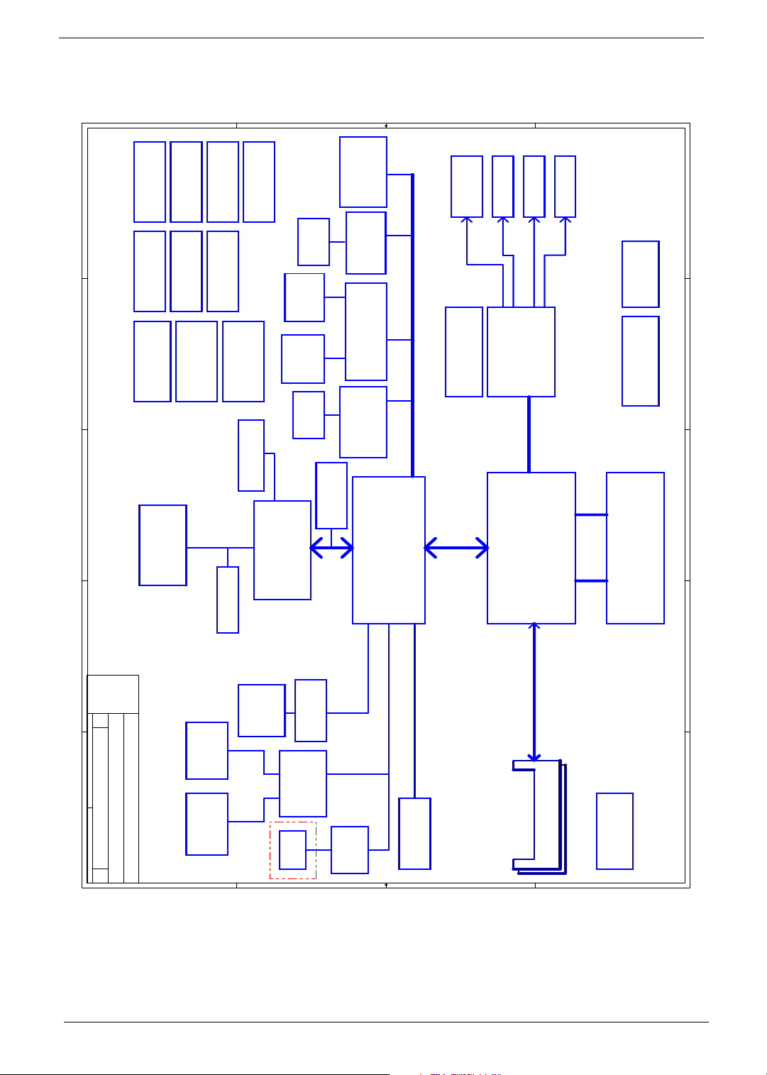
System Block Diagram
IDSEL:AD19
(PIRQH#,PIRQG#,GNT#4,REQ#4)
IDSEL:AD20
(PIRQA,B#,GNT#2,REQ#2),SIRQ
PCI BUS
+3VALW 33MHz
IDSEL:AD18
(PIRQG#,PIRQH#,GNT#1,REQ#1)
page 26
+1.5VS
100MHz
G781-1
C C
Frame Buffer
64/128
page 22,23
Thermal(VGA)
+3VS
DMI
CRT CONN
LVDS CONN
page 25
page 24
CRT Signal
Internal LVDS
+2.5VS
+1.2VS
page 18,19,20,21
+3VS
+1.5VS
+1.8VS
+VGA_CORE
ATI M24P
PCI-E 16X
+1.5VS
+2.5V
+VCCP
+3VS
+2.5VS
1257BGA
page 9,10,11,12,13
Alviso
page 25
INTEL
page 33
X BUS
page 34
+VCC_5IN1 +S1_VCC
Reader
page 33
+S1_VPP
Slot
page 36
KB910
B B
CONN
1394
Card
PCMCIA
RJ45
+3VS
+5VS
page 43
+3VALW
33MHz
Minipci CONN X2
WIRELESS
TV Turner
page 37,38
1394 Controller
+3VS
VT6301S
page 34
+S1_VCC
+3VS
CardBus Controller
ENE CB712
page 32
RTL8110SBL
/8100CL
+3VALW
page 35
Port DEBUG
+2.5VS
+1.5V
+1.5VS
609 BGA
page 27,28,29,30
LPC BUS
(PIRQE#,GNT#0,REQ#0)
(PIRQF#,GNT#3,REQ#3)
+3V
ICH6-M
IDSEL:AD16
IDSEL:AD17
+3VS
INTEL
A A
+1.8VS/
+VGA_CORE
CHARGER
CPU_CORE
page 55
5
page 49
3V/5V/12V
page 51
DC/DC Interface
4
page 47
+1.25VS
page 52
page 43
2.5V/+1.2VS/
SW & LED
page 54
page 48
Power On/Off
+1.5VS/+VCCP
page 53
DC IN
RTC BATT
page 50
SST39VF040
page 42
3
+5VS
page 43
+3VALW
Touch Pad &
LID SW
+5VS
page 41
Int.KBD
page 43
TV OUT
+VCCP 400/533 MHz
H_A#(3..31) H_D#(0..63)
System Bus
D D
+5VS
page 8
G781
page 8
+VCCP (1.05V)
+CPU_CORE
uFCPGA CPU
478pin
page 5,6,7
Model : AS9100
FAN
Thermal(CPU)
+3VS
Pentium-M
Dothan
5
4
3
Memory BUS
(DDRI)
48MHz
2
Title
Size
Date: Sheet
妨茗
, 27, 2004
System Block Diagram
Acer Inc.
1
258
of
+5VAMP +5VAMP
Speaker
page 45
MIC CONN
page 45
AMP & INT.
HeadPhone &
+5VCD
page 31
CD-ROM
IDE
+3VS
+5VAMP
page 44
page 36
RJ11
Parallel ATA
+5VS
page 31
AC97 Codec
ALC250
24.576MHz
ATA100
USB[0,2,4,6]
AC-LINK
+5VALW
USB Ports X4
+3V
+3VS
+5VS
MDC
page 39
Cable
page 40
+1.25VS
+2.5V
page 14,15
2.5V 333 MHz
BANK 0, 1, 2, 3
DDRI-DIMM X2
+3VS
Clock Generator
ICS954226
page 17
2
1
Chapter 1 3
Page 11
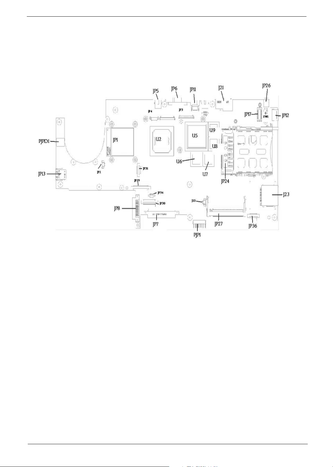
Board Layout
Top Vi e w
PJPD1 DC JACK JP5 TV-OUT CONNECTOR
JP13 DUAL USB CONNECTOR JP6 CRT CORRECTOR
JP1 CPU SOCKET JP11 SINGLE USB CONNECTOR
JP2 FAN CONNECTOR JP3 LCD CONNECTOR
JP31 LED CONNECTOR JP4 INVERTER CONNECTOR
JP29 KEYBOARD CONNECTOR U2 NORTH BRIDGE
JP8 CD-ROM CONNECTOR U5 GRAPHICS CHIP
JP7 HDD CONNECTOR U6 VGA MEMORY CHIP
JP34 TOUCHPAD CONNECTOR U7 VGA MEMORY CHIP
JP30 SW DJ BOARD CONNECTOR U8 VGA MEMORY CHIP
J25 NOT INSTALL U9 VGA MEMORY CHIP
PJP1 BATTERY CONNECTOR JP24 CARD BUS SOCKET
JP27 MINI PCI CONNECTOR J23 MS/SD/MMC CARD READER CONNECTOR
JP36 SPEAKER CONNECTOR JP17 MDC CONNECTOR
JP12 SINGLE USB CONNECTOR JP26 IEEE1394 CONNECTOR
SW1 LID SWITCH J21 ETHERNET CONNECTOR
4 Aspire 9100
Page 12
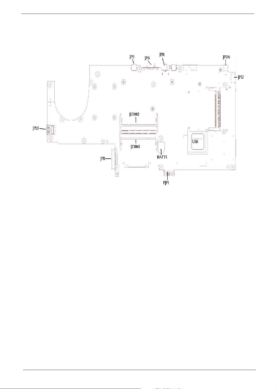
Bottom View
JP13 DUAL USB CONNECTOR JP5 TV-OUT CONNECTOR
JP8 CD-ROM CONNECTOR JP6 CRT CONNECTOR
JDIM1 MEMORY CONNECTOR JP11 SINGEL USB CONNECTOR
JDIM2 MEMORY CONNECTOR JP26 IEEE1394 CONNECTOR
BATT1 COIN CELL CONNECTOR JP12 SINGEL USB CONNECTOR
PJP1 BATTERY CONNECTOR U16 SOUTH BRIDGE
Chapter 1 5
Page 13
Panel
This is a brief introduction to the I/O ports, the features and the indicators.
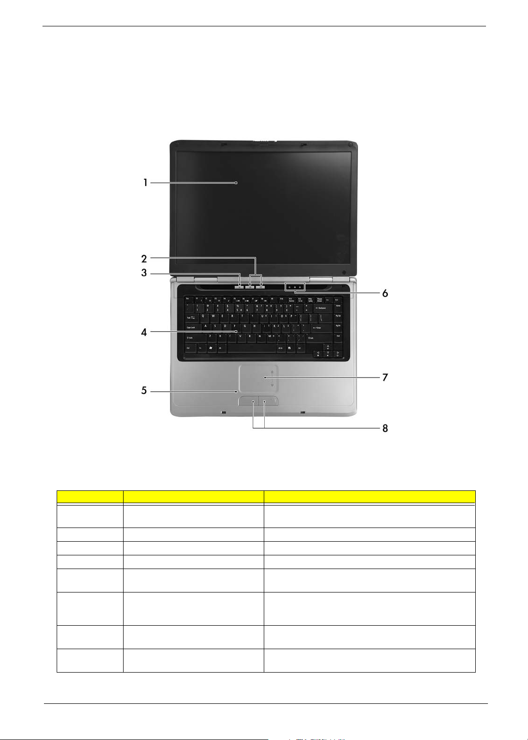
Front Panel
# Item Description
1 Display screen Also called LCD (Liquid Crystal Display), displays computer
output.
2 Launch keys Buttons for launching frequently used programs.
3 Power button Turns the computer on and off.
4 Keyboard Inputs data into your computer.
5 Palmrest Comfortable support area for your hands when you use the
6 Status indicators LEDs (Light Emitting Diodes) that turn on and off to show
7 Touchpad Touch-sensitive pointing device which functions like a
8 Click buttons (Left and right) The left and right buttons function like the left and right
computer.
the status of the computer and its functions and
components.
computer mouse.
mouse buttons.
6 Aspire 9100
Page 14
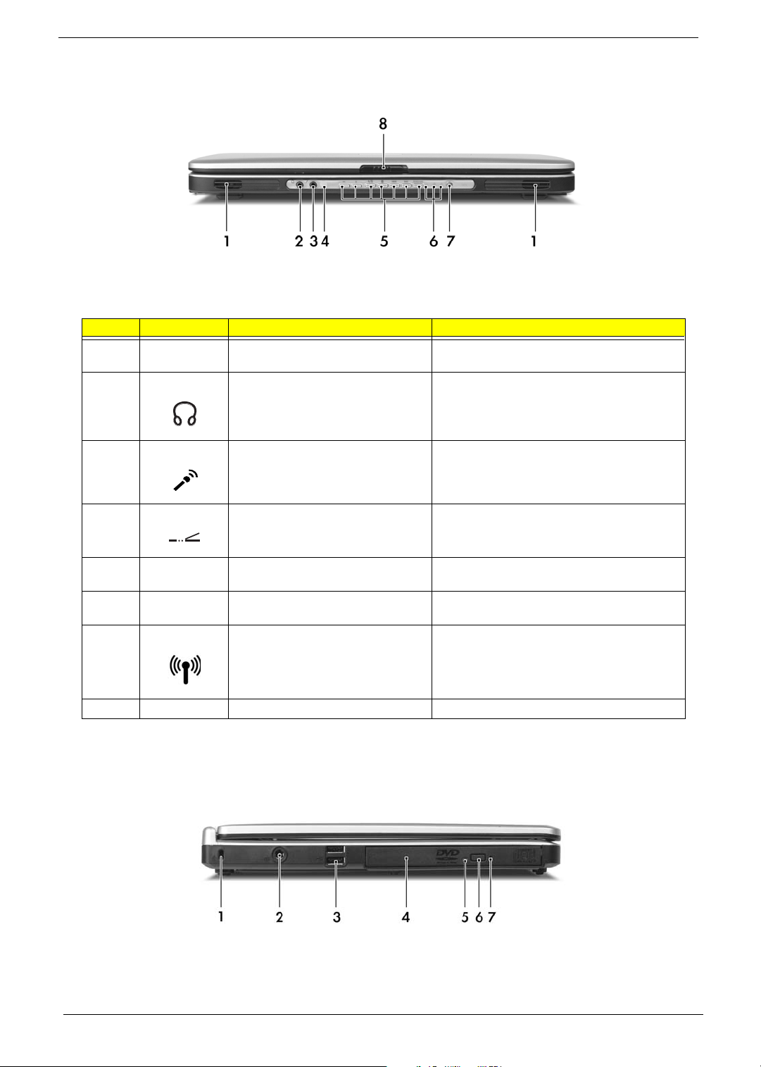
Closed front viewLeft Panel
# Icon Item/ Port Description
1 Speakers Left and right speakers deliver stereo audio
output.
2 Speaker/Line-Out/Headphone jack Connects to audio line-out devices (e.g.,
speakers, headphones).
3 Mic-in jack Accepts inputs from external microphone.
4 CIR Receiver Receives remote control infrared signals.
5 Arcade/Media/Volume buttons For use with Acer Arcade and other media
6 Indicators (power, Hard disc, and
battery)
7 Wireless communication button/
indicator
8 Latch Locks and releases the lid.
playing programs.
Light to indicate the computer’s status
Press to enable/disable Wireless function. Lights
to indicate the status of wireless LAN
communications.
Left view
Chapter 1 7
Page 15
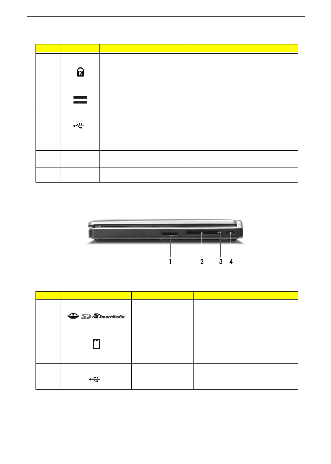
# Icon Item/ Port Description
1 Security keylock Connects to a Kensington-compatible computer
2 Power jack Connects to an AC adaptor.
3 Two USB 2.0 ports Connect to Universal Serial Bus (USB) 2.0
security lock.
devices (e.g., USB mouse, USB camera).
4 Optical drive Internal optical drive; accepts CDs or DVDs
5 LED indicator Lights up when the optical drive is active.
6 Optical drive eject button Ejects the optical drive tray from the drive.
7 Emergency eject hole Ejects the optical drive tray when the computer is
depending on the optical drive type.
turned off.
Right Panel
# Icon Item/ Port Description
1 3-in-1 card reader Accepts MS, SM and SD card.
Note: Only one card can operate at any given
time.
2 PC card slot Connects to one Type II CardBus PC Card.
3 PC Card slot eject button Ejects the PC Card fom the slot.
4 USB 2.0 port Connects to Universal Serial Bus (USB) 2.0
devices (e.g., USB mouse, USB camera).
8 Aspire 9100
Page 16
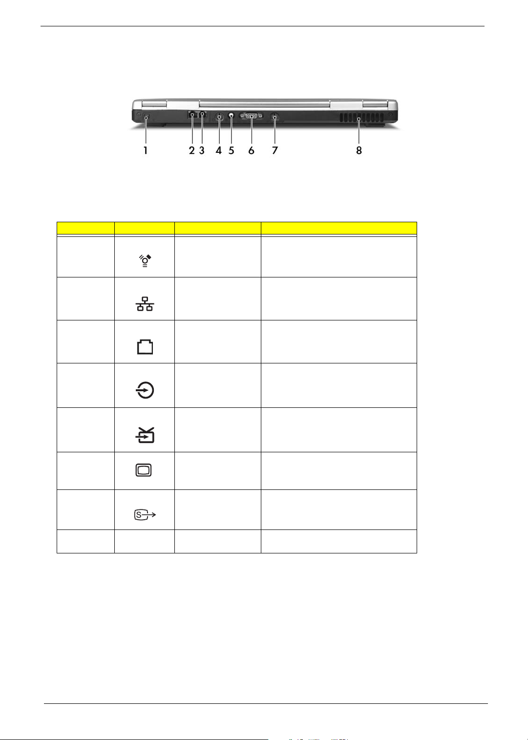
Rear Panel
# Icon Port Description
1 IEEE 1394 port Connects to IEEE 1394 devices.
2 Network jack Connects to an Ethernet 10/100/1000-
based network (for selected models).
3 Modem jack Connects to a phone line.
4 Audio/video in port Supports both audio and video input.
5 Antenna port Connects to a (PAL/NTSC) TV antenna
cable.
6 External display port Connects to a display device (e.g., external
7 S-video out port Connects ta television or display device
8 Ventilation slots Enable the computer to stay cool, even
monitor, LCD projector).
with S-video input.
after prolonged use.
Chapter 1 9
Page 17
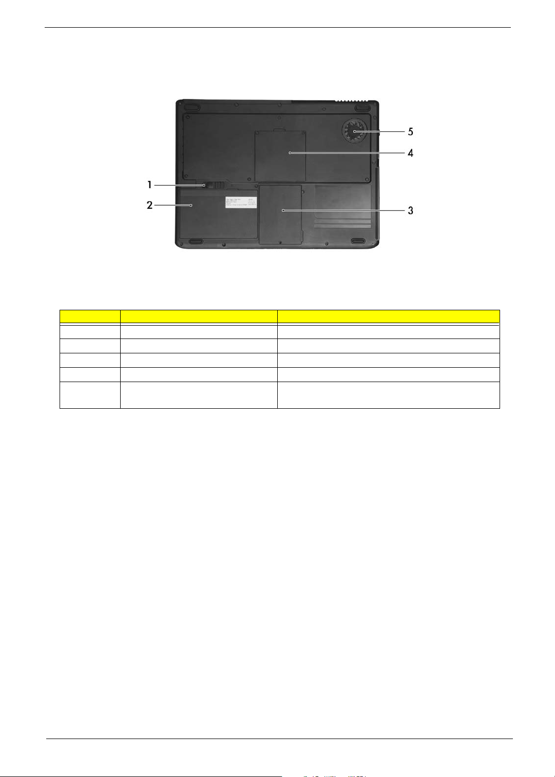
Bottom Panel
# Item Description
1 Battery release latch Unlatches the battery to remove the battery pack.
2 Battery bay Houses the computer’s battery pack.
3 Hard disc bay Houses the computer’s hard disc (secured by a screw).
4 Memory comparment House the computer’s main memory and Mini PCI Card.
5 Cooling fan Helps keep the computer cool.
Note: Do not cover or obstruct the opening of the fan.
10 Aspire 9100
Page 18
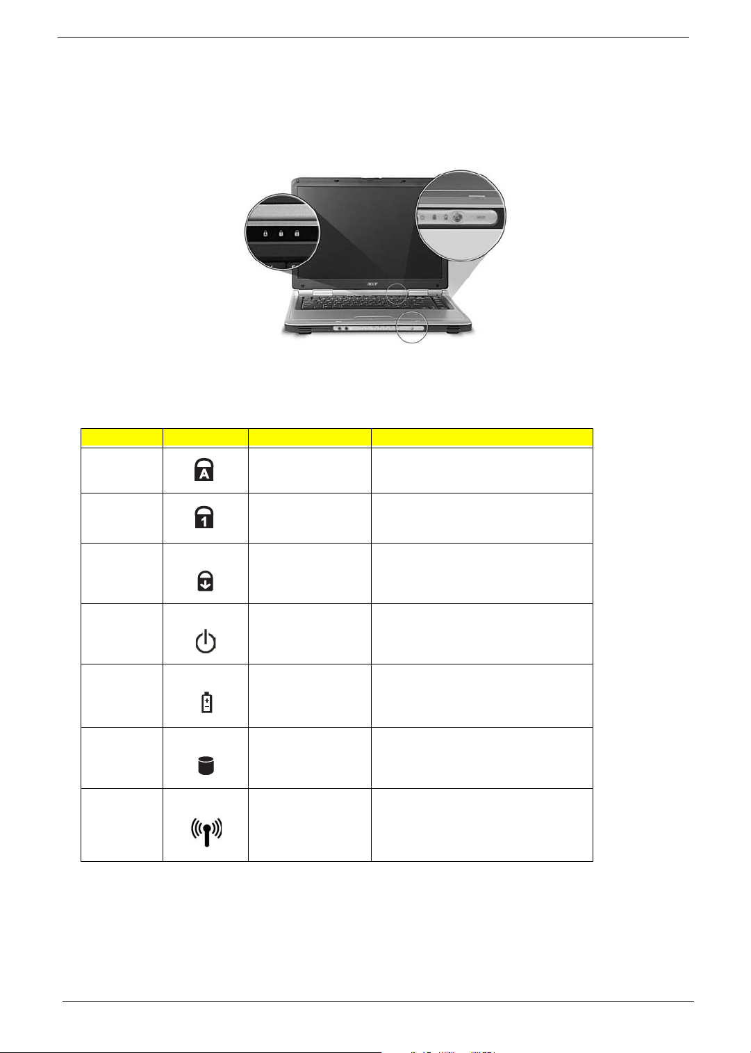
Indicators
The computer has six easy-to-read status icons on the upper-right above the keyboard. In addition, there are
four indicators located on the front panel.
# Icon Function Description
1 Caps Lock Lights when Caps Lock is activated.
2 Num Lock
(Fn-F11)
3 Scroll Lock Lights when the computer enters Standby
4 Power Lights when the computer is on.
5 Battery indicator Lights when the battery is being charged.
Media activity Lights when the hard disc or optical drive is
7 Wireless
communication
Lights when Numeric Lock is activated.
mode and blinks when it enters into or
resumes from hibernation mode.
active.
Lights to indicate the status of wireless
LAN communications.
Chapter 1 11
Page 19
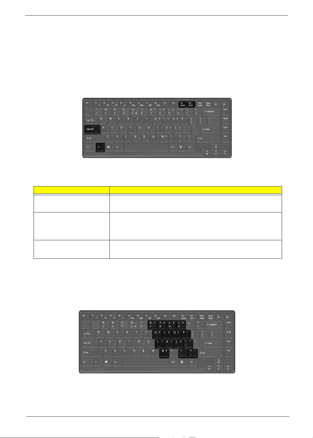
Using the keyboard
The keyboard has full-sized keys and an embedded keypad, separate cursor keys, two Windows keys and
twelve function keys.
Lock keys
The keyboard has three lock keys which you can toggle on and off.
Lock key Description
Caps Lock
@
Num Lock (Fn-F11)
]
Scroll Lock (Fn-F12)
[
When @is on, all alphabetic characters typed are in uppercase.
When ] is on, the embedded keypad is in numeric mode. The keys function
as a calculator (complete with the arithmetic operators ), -, *, and /). Use this mode
when you need to do a lot of numeric data entry. A better solution would be to
connect an external keypad.
When [ is on, the screen moves one line up or down when you press the up
or down arrow keys respectively.
[ does not work with some applications.
Embedded numeric keypad
The embedded numeric keypad functions like a desktop numeric keypad. It is indicated by small characters
located on the upper right corner of the keycaps.
12 Aspire 9100
Page 20
Desired access Num lock on Num lock off
Type numbers Use embedded keypad in the sam way as
the numeric keypad on a standard
keyboard.
Type letters Hope Fn while typing letters on embedded
keypad.
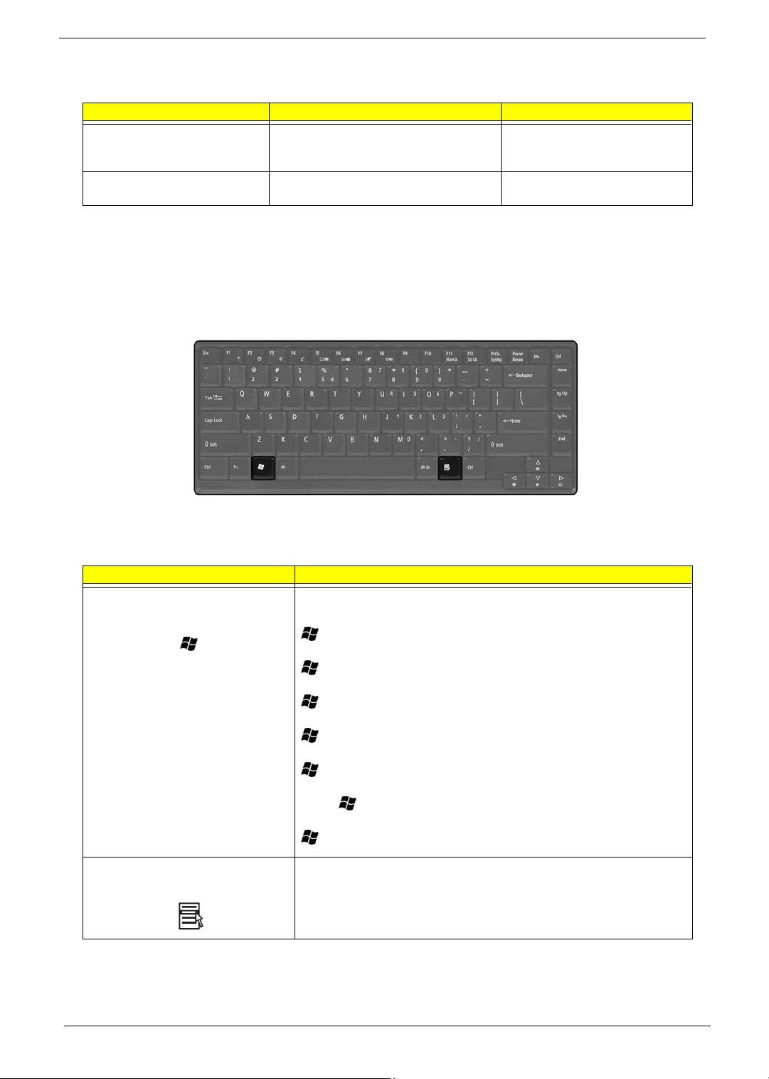
Windows keys
The keyboard has two keys that perform Windows-specific functions.
Type the letters in a normal manner.
Keys Description
Windows logo key
Start button. Combinations with this key perform shortcut functions. Below
are a few examples:
+ <Tab> (Activates the next Taskbar button)
+ <E> (Opens the My Computer window)
+ <F1> (Opens Help and Support)
+ <F> (Opens the Find: All Files dialog box)
+ M (Minimizes all windows)
j+ + M (Undoes the minimize all windows)
+ R (Opens the Run dialog box)
Application key This key has the same effect as clicking the right mouse button; it opens the
application’s context menu.
Chapter 1 13
Page 21
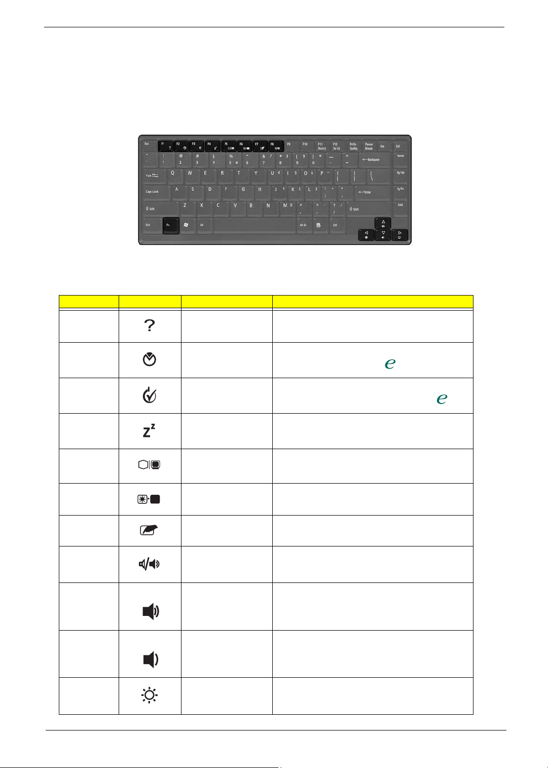
Hot Keys
"Acer
"Acer
The computer employs hot keys or key combinations to access most of the computer’s controls like screen
contrast and brightness, volume output and the BIOS Utility.
To activate hot keys, press and hold the Fn key before pressing the other key in the hot key combination.
Hot Key Icon Function Description
Fn-
l
Hotkey help Displays a list of the hotkeys and their functions.
Fn-
Fn-
Fn-
Fn-
Fn-
Fn-
Fn-
Fn-
Fn-
m
n
o
p
q
r
s
w
y
Acer eSetting Launches the Acer eSetting in the Acer eManager set
by the Acer Empowering key “ “
Acer
ePowerManagement
Sleep Puts the computer in Sleep mode.
Display toggle Switches display output between the display screen,
Screen blank Turns the display screen backlight off to save power.
Touchpad Toggle Turns the internal touchpad on and off.
Speaker on/off Turns the speakers on and off; mutes the sound.
Volume up Increases the sound volume.
Volume down Decreases the sound volume.
Launches the Acer ePower-Management in the Acer
eManager set by the Acer Empowering key” “.
external monitor (if connected) and both the display
screen and external monitor.
Press any key to return.
Fn-
x
14 Aspire 9100
Brightness up Increases the screen brightness.
Page 22
Hot Key Icon Function Description
"Acer
"Acer
Fn-
¨
z
Brightness down Decreases the screen brightness.
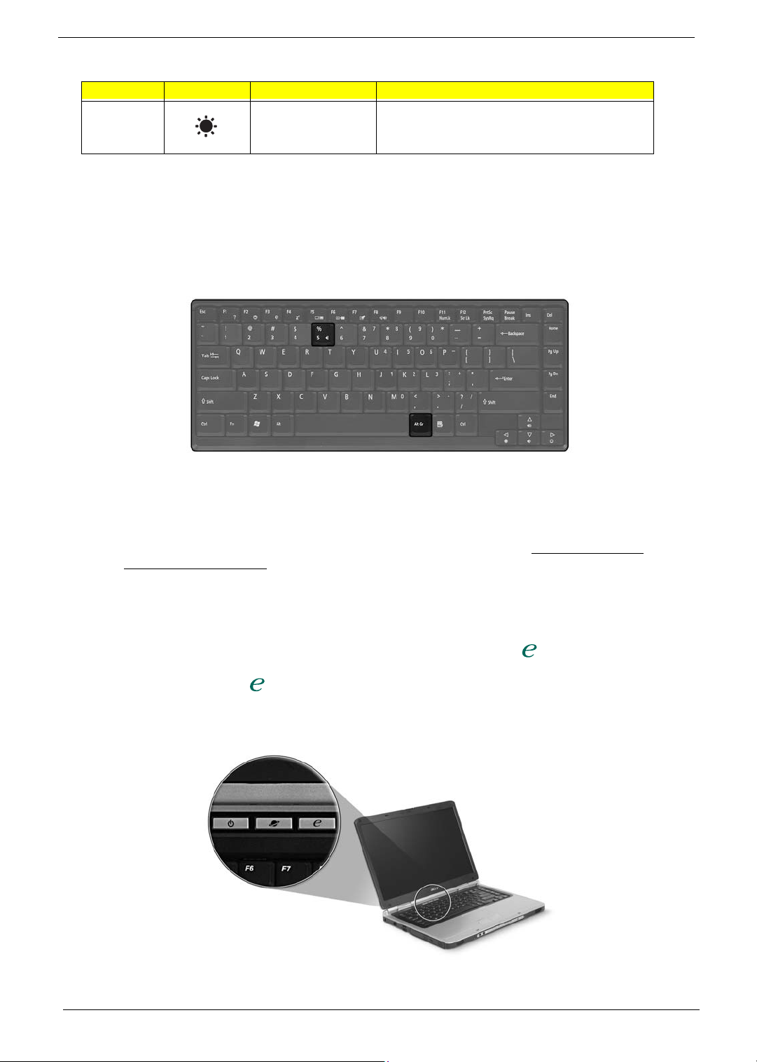
The Euro symbol
If your keyboard layout is set to United States-International or United Kingdom or if you have a keyboard with a
European layout, you can type the Euro symbol on your keyboard.
1. Open a text editor or word processor.
2. Hold <Alt Gr> and then press the Euro symbol at the upper-center of the keyboard.
NOTE: Sme fonts and software do not support the Euro symbol. Please refer to www.microsoft.com/
typography/faq/faq12.htm for more information.
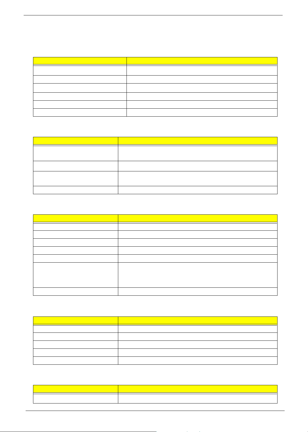
Launch Keys
Located above the keyboard next to the power button are two buttons. These buttons are called launch keys.
They are designated as the Internet browser, and the Acer Empowering key “ “.
Press the Empowering key “ “ to run the Acer eManager. Please see an Internet browser as default, but it
can be reset by users.
Chapter 1 15
Page 23

# Icon Function Description
"Acer
1 Web broswer Internet browser apllication (User-
2 eManager eManager launch key (User-programmable)
programmable)
16 Aspire 9100
Page 24
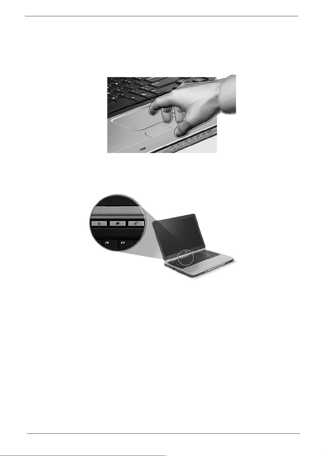
To u c h p a d
The built-in touchpad is a pointing device that senses movement on its surface. This means the cursor
responds as you move your finger on the surface of the touchpad. The central location on the palmrest
provides optimum comfort and suuport.
Touchpad basics
The following items teach you how to use the touchpad:
* Move your finger across the touchpad (2) to move the cursor.
* Press the left (1) and right (3) buttons located on the edge of the touchpad to do selection and execution
functions. These two buttons are similar to the left and right buttons on a mouse. Tapping on the touchapd is
the same as clicking the left button.
Chapter 1 17
Page 25

Function Left button Right button Touchpad
Execute Click twice quickly. Tap twice (at the same speed
Select Click once. Tap once.
Drag Click and hold, then use
Access
context menu
finger to drag the cursor on
the touchpad.
Click once.
as double-clicking a mouse
button).
Tap twice (at the same speed
as double-clicking a mouse
button); hold finger to the
touchpad on the second tap
and drag the cursor.
NOTE: Keep your fingers dry and clean when using the touchpad. Also keep the touchpad dry and clean. The
touchpad is sensitive to finger movement, hence, the lighter the touch, the better the response. Taping
harder will not increase the touchpad’s responsiveness.
18 Aspire 9100
Page 26
Hardware Specifications and Configurations
System Board Major Chip
Item Controller
System core logic
Audio controller RealTek ALC250 AC 97 Codec
Video controller
Keyboard controller KB910
CardBus Controller ENE CB712
IEEE Controller VIA VT6301S
Processor
Item Specification
CPU type
CPU package
CPU core voltage Low speed: 0.8V
CPU I/O voltage 1.2V
Intel® Alviso(north bridge)+Intel® ICH6-M (south bridge)
ATI M24P (ATI MOBILITY
Intel® Pentium® M processor 730/740/750/760/770 at 1.6, 1.73, 1.86, 2.0,
2.13GHz, 533Mhz FSB
µ
478-pin FCPGA
High speed: 1.5V
TM
RADEONTM)
BIOS
Item Specification
BIOS vendor Insyde BIOS
BIOS Version AS9100 V1.00
BIOS ROM type Flash ROM
BIOS ROM size 512K
BIOS package 32 Pin PLCC
Supported protocols ACPI 2.0 (if available, at least 1.0b), SMBIOS 2.3, PCI 2.2, Boot Block,
PXE 2.0, Mobile PC2001, Hard Disk Password, INT 13h Extensions, PCI
Bus Power Management interface Specification, EI Torito-Bootable CDROM Format Specification V1.0, Simple Boot Flag 1.0
BIOS password control Set by switch, see SW1 settings
Second Level Cache
Item Specification
Cache controller Built-in CPU
Cache size 1M
1st level cache control Always Enabled
2nd level cache control Always Enabled
Cache scheme control Fixed-in write back
System Memory
Item Specification
Memory controller
Intel® Alviso
Chapter 1 19
Page 27
System Memory
Item Specification
Onboard memory size 0MB
DIMM socket number 2 Sockets
Supports memory size per socket 256MB
Supports maximum memory size 2048MB
Supports DIMM type DDR-DRAM
Supports DIMM Speed 333 MHz
Supports DIMM voltage 2.5 V/1.25V
Supports DIMM package 200-pin so-DIMM
Memory module combinations You can install memory modules in any combinations as long as they
match the above specifications .
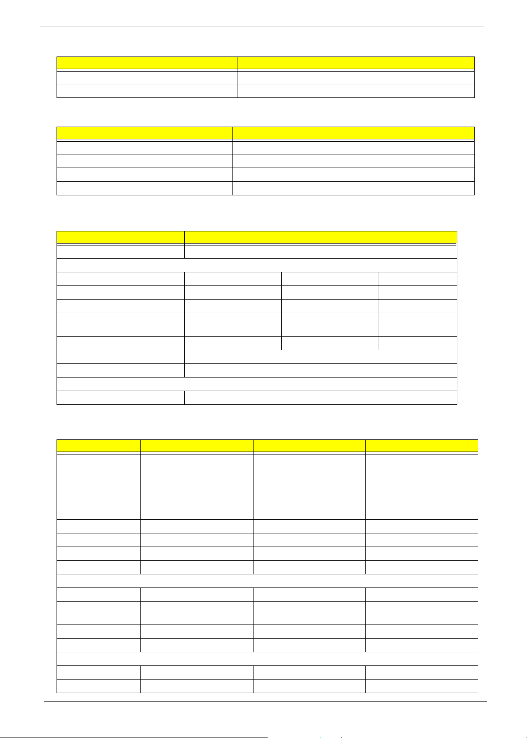
Memory Combinations
Slot 1 Slot 2 Tota l M e mory
0MB 256MB 256MB
0MB 512MB 512MB
0MB 1024MB 1024MB
256MB 0MB 256MB
256MB 256MB 512MB
256MB 512MB 768MB
256MB 1024MB 1280MB
512MB 0MB 512MB
512MB 256MB 768MB
512MB 512MB 1024MB
512MB 1024MB 1536MB
1024MB 0MB 1024MB
1024MB 256MB 1280MB
1024MB 512MB 1536MB
1024MB 1024MB 2048MB
Above table lists some system memory configurations. You may combine DIMMs with various capacities to
form other combinations.
LAN Interface
Item Specification
Chipset Realtek RTL8110SBL
Supports LAN protocol 10/100/1000Mbps
LAN connector type RJ45
LAN connector location Rear side
Modem Interface
Item Specification
Chipset CS1037 Internal Agere Scorpio chipset (Scorpio+CSP1037B)
Fax modem data baud rate (bps) 14.4K
Data modem data baud rate (bps) 56K
Supports modem protocol V.92MDC
20 Aspire 9100
Page 28
Modem Interface
Item Specification
Modem connector type RJ11
Modem connector location Rear side
Wireless Module 802.11b/g (optional device)
Item Specification
Chipset Intel
Data throughput 11M~54M bps
Protocol 802.11 b+g
Interface Mini-PCI type II
Floppy Disk Drive Interface
Item Specification
Vendor & model name There is no FDD module for this product
Floppy Disk Specifications
Media recognition 2DD (720KB) 2HD (1.2 MB, 3 mode) 2HD (1.44MB)
Sectors/track 9 15 18
Tracks 80 80 80
Data transfer rate
(Kbit/s)
Rotational speed (RPM) 300 360 300
Read/write heads 2
Encoding method MFM
Power Requirement
Input Voltage (V) +5V
1 MB 1.6 MB 2 MB
.
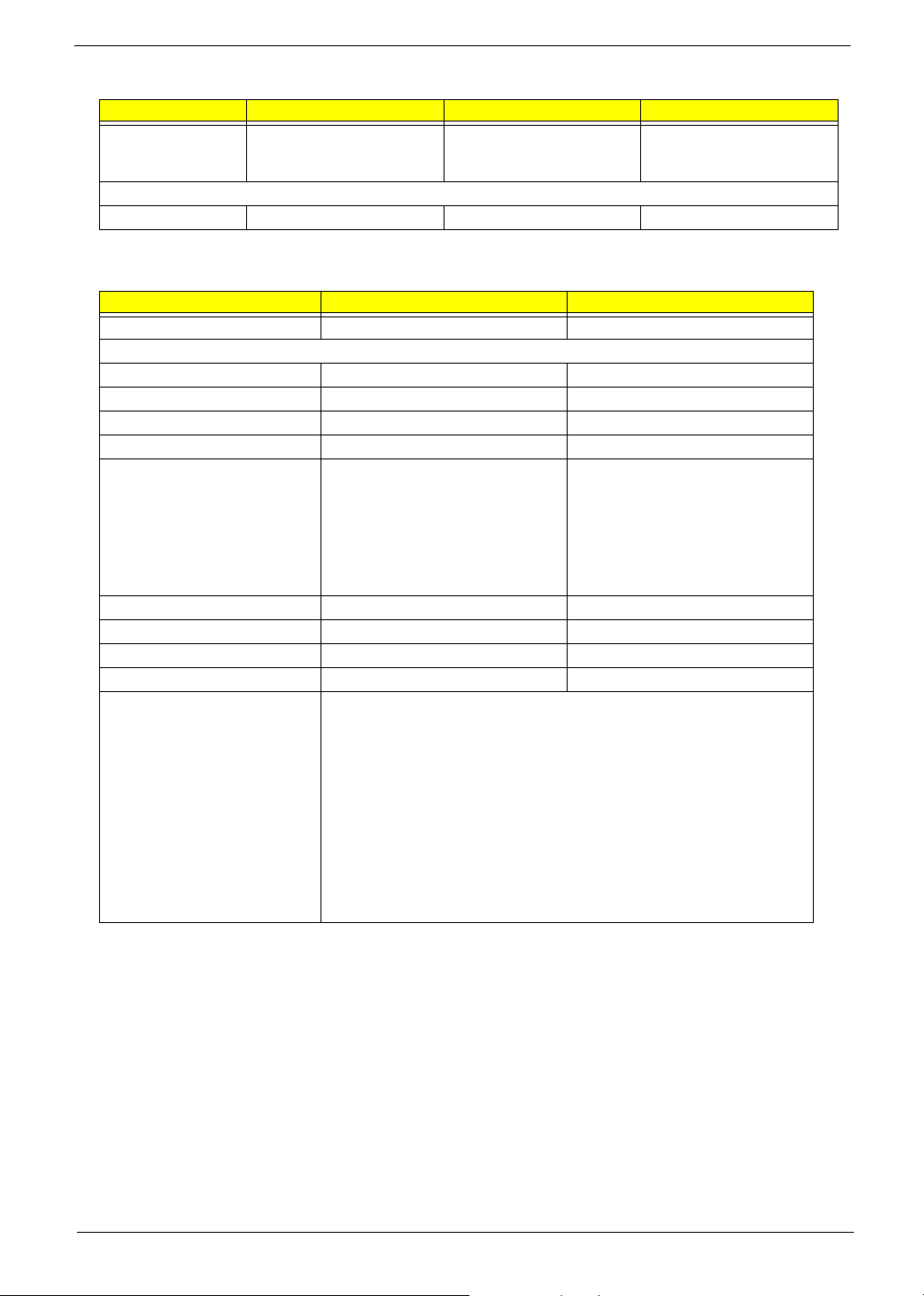
Hard Disk Drive Interface
Item
Vendor & Model
Name
Capacity (MB) 60000 80000 100000
Bytes per sector 512 512 512
Logical heads 16 16 16
Logical sectors 63 63 63
Drive Format
Logical cylinders 16383 16383 16383
Physical read/write
heads
Disks 2/2/4 2/2/4 2
Spindle speed (RPM) 4200RPM 4200RPM 4200RPM
Performance Specifications
Buffer size 8MBytes (8192kbytes) 8MBytes (8192kbytes) 8MBytes
In terf ace ATA- 6 ATA/ATAPI -6 ATA/ ATAPI- 6
HGST MORAGA
IC25N060ATMR04-0
08K0634
Seagate N2 ST960821A
TOSHIBA PLUTO
MK6025GAS
3/3/4 4/3/2 4
HGST MORAGA
IC25N080ATMR04-0 08K635
Seagate N2 ST9808210A
TOSHIBA PLUTO
MK6025GAS
TOSHIBA PLUTO
MK1031GAS
SEAGATE N2 ST9100822A
Chapter 1 21
Page 29
Hard Disk Drive Interface
Item
Data transfer, rate
(host~buffer, Mbytes/
s)
DC Power Requirements
Voltage tolerance 5 +/- 5% 5 +/- 5% 5 +/- 5%
100 MB/Sec 100 MB/Sec 100 MB/Sec
Combo Drive Interface
Item Specification Remark
Vendor & model name DVD/CDRW TOSHIBA TS-L462A
General Specification
Interface Enhanced IDE (ATAPI)
Disc Diameter 8cm/12cm
Loading Type Drawer Type
Drive Mounting Horizontal/Vertical
Read/Write Read Speed:
Max. 24X(3,600 KB/sec) for CD-ROM
Max. 24X(3,600 KB/sec) for CD-RW
Write Speed:
Max. 24X(3,600 KB/sec) for CD-R
Max. 10X(1,500 KB/sec) for CD-RW
Max. 24X(3,600 KB/sec) for US-RW
Mounting Orientation Horizontal/Vertical All angles
Buffer Under Run 2MB
Power consumption DC +5v/1.2A
Interface Enhanced IDE(ATAPI) compatible
Media compatibility CD:
120mm CD-ROM (Read Only)
80mm CD
800/700/650/550MB CD-Recordable (Read & Write)
700/650MB CD-Rewritable (Read & Write)
700/650MB High Speed CD-Rewritable (Read & Write)
DVD:
5/9/10/18 DVD-Single/Dual (PTP, OTP)
3.9/4.7G DVD-R (Read Only)
4.7GDVD+R (Read Only)
DVD±RW (Read only)
80mm DVD
CAV 24X
CAV 24X
P-CAV 24X/20X/16X ; CLV 10X/8X/4X
CLV 10X/4X
P-CAV 24X/16X
22 Aspire 9100
Page 30
Combo Drive Interface
Item Specification Remark
Format compatibility CD
CD-DA (Red Book) - Standard Audio CD & CD-TEXT
CD-ROM (Yellow Book Mode1 & 2) - Standard Data
CD-ROM XA (Mode2 Form1 & 2) - Photo CD, Multi-Session
CD-I /FMV (Green Book, Mode2 Form1 & 2, Ready, Bridge)
CD-Extra/ CD-Plus (Blue Book) - Audio & Text/Video
Video-CD (White Book) - MPEG1 Video
DVD
DVD-ROM (Book 1.02),
DVD-Video (Book 1.1)
DVD-R (Book 1.0, 3.9G)
DVD-R (Book 2.0, 4.7G) - General & Authoring
DVD+R (Version 1.0)
DVD±RW
Play DVD-AUDIO except the case that required CPPM
(Content protection for prerecorded Media)
Write Method
Loading mechanism Load: Manual
Release: (a) Electrical Release
(Release Button)
(b) Release by ATAPI
command
(c) Emergency Release
Power Requirement
Input Voltage DC +5V+/- 5% (operation)
DC +5V+/- 8% (start up)
DVD-RW Interface
Item Specification
Vendor & model name TOSHIBA TS-L532A
Performance Specification
Transfer rate (KB/sec)
(1) Read DVD-ROM
DVD-R
CD-ROM
(2) Write CD-R
CD-RW
HS-RW
US-RW
(3) ATAPI Interface
PIO mode
DMA mode
Ultra DMA mode
Buffer Memory 2MB
Interface Enhanced IDE(ATAPI) compatible
Applicable disc format Read:
MAX 8X CAV (MAX 10800kB/s)
MAX 4X CAV (MAX 5400kB/s)
MAX 24X CAV (MAX 3600kB/s)
4X, 8X (CLV), MAX. 24X(ZCLV)
4X (CLV)
4X, 8X, 10X (CLV)
8X, 10X(CLV), MAX. 16X (ZCLV)
16.6MB/s: PIO mode4
16.6MB/s: Multi word mode2
33.3MB/s: Ultra DMA mode2
copy-protected DVD discs, CD-ROM, CD audio, DVD-ROM and
DVD-RAM, DVD-R/-RW, DVD+R/+RW and CD-R/-RW, DVD-ROM,
DVD-R/+R, DVD-R/+R, DVD-RW/+RW, 4.38GB DVD-RAM, CD-DA
discs, CD-ROM discs, CD-R discs, CD-RW discs
Write:
CD-R, CD-RW, high-speed CD-RW, Ultra-speed CD-RW, DVD-R,
DVD-RW, DVD+R, DVD+RW
Chapter 1 23
Page 31

DVD-RW Interface
Item Specification
Loading mechanism Load: Manual
Release: (a) Electrical Release (Release Button)
(b) Release by ATAPI command
(c) Emergency Release
Power Requirement
Input Voltage 5 V +/- 5 % (Operating)
Audio Interface
Item Specification
Audio Controller Realtek ALC250
Audio onboard or optional Built-in
Mono or Stereo Stereo
Resolution 18 bit stereo full duplex
Compatibility AC97 2.2 S/PDIF extension compliant codec
Sampling rate 1Hz resolution VSR (Variable Sampling Rate)
Internal microphone Yes
Internal speaker / Quantity Yes
Supports PnP DMA channel DMA channel 0
DMA channel 1
Supports PnP IRQ IRQ10, IRQ11
Video Interface
Item Specification
Vendor & Model Name
Video memory size 128MB
Chip voltage Core / 2.5V, 1.5V,
Supports ZV (Zoomed Video) port NO
Graph interface 4X AGP (Accelerated Graphic Port) Bus
Maximum resolution LCD 1600X1200 (UXGA)
Maximum resolution CRT 2048X1536@60HZ
ATI M24P (ATI MOBILITY
TM
RADEON
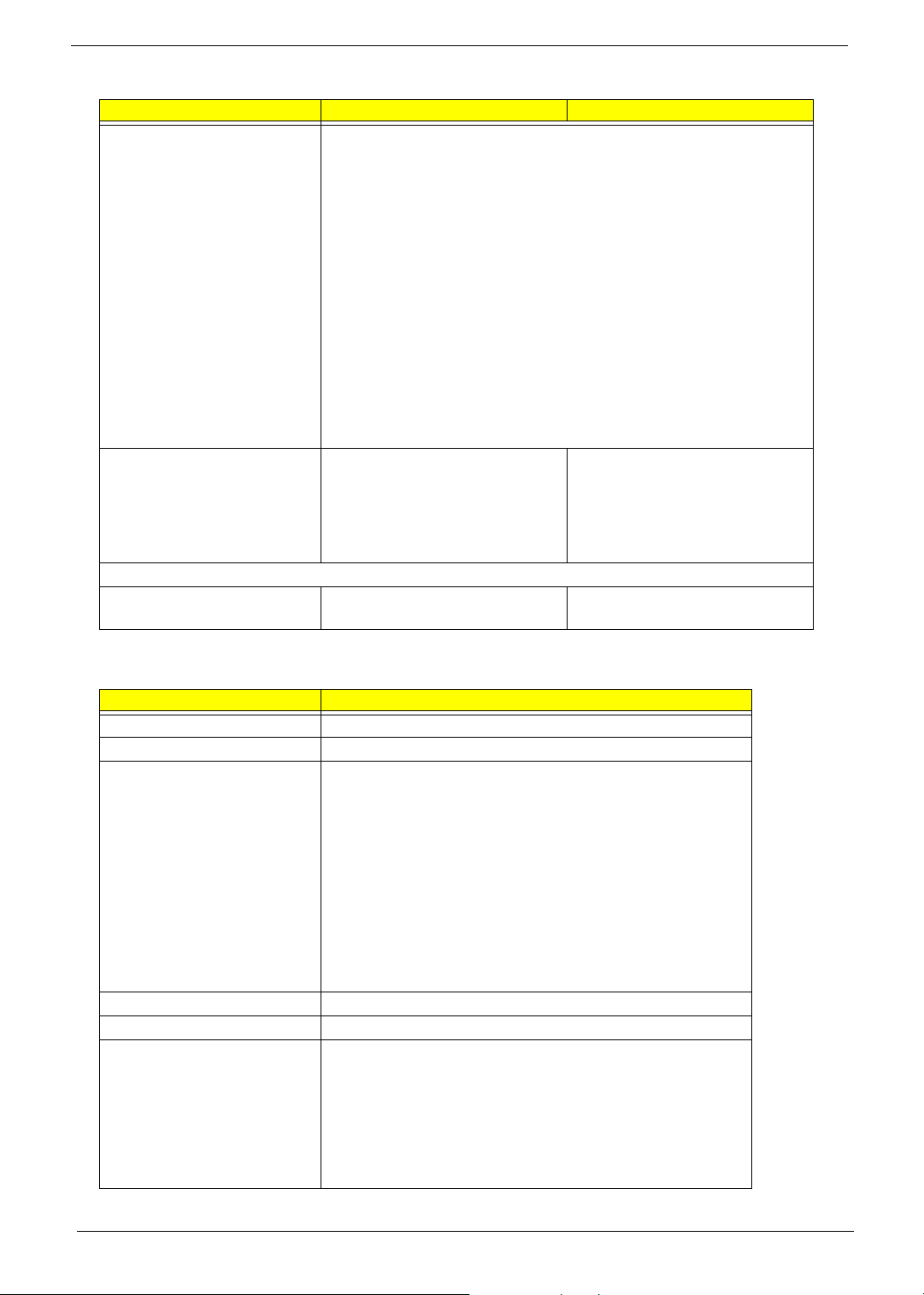
Video Resolutions Mode
Monitor Resolution Hz
2D Display Mode
640x480 120
800x600 120
1024x768 120
1152X864 120
1280X1024 120
1600x1200 85
1920x1080*16:9 75
1920x1200 75
TM)
24 Aspire 9100
Page 32

Video Resolutions Mode
Monitor Resolution Hz
1920x1440 75
2048x1536 60
Resolution, colors and maximum refersh rate (Hz) in 256, 65K or 16.7M colors.
NOTE: 16:9 aspect ratio monitors are supported on 1920x1080 and 848x480 on Windows(R)XP, Windows(R)
2000 and Windows(R)ME. The complete list of resolutions depends on the driver version and operating
system. NOTE: resolutions are limited by the performance of the attached monitor.
USB Port
Item Specification
USB Compliancy Level 2.0
OHCI USB 2.0
Number of USB port 3
Location Two on the left side; one on the right side
Serial port function control Enable/Disable by BIOS Setup
PCMCIA Port
Item Specification
PCMCIA controller ENE 712
Supports card type Type II (No Tpye III)
Number of slots One type II
Access location Right side
Supports ZV (Zoomed Video) port NO
Supports 32 bit CardBus Yes (IRQ17)
Keyboard
Item Specification
Keyboard controller ENE 910 keyboard controller
Keyboard vendor Chicony/JME
Total number of keypads 86-US/87-UK/88-BZ/91-JA key
Windows keys Yes
Internal & external keyboard work simultaneously Yes
Battery
Item Specification
Vendor & model name SANYO 4UR18650F-2-CPL-15
SONY LIP8151CMPCFSY6
Battery Type Lithium-ION
Pack capacity 4300mAH
Nominal voltage 14.8V
Number of battery cell 8
Package configuration 4P2S
Package voltage 41.8V / 9.6V
Chapter 1 25
Page 33

LCD
Item Specification
Vendor & model name SAMSUNG LTN154X3-L01-G
Screen Diagonal (mm) 15.4inch 15.4inch
Active Area (mm) 331.2(H)x207.0(V) 331.2(H)x207.0(V)
Display resolution (pixels) WXGA (1080x800) WXGA (1080x800)
Pixel Pitch 0.25875(H)x0.25875(H)mm 0.25875(H)x0.25875(H)mm
Pixel Arrangement RGB vertical stripe RGB vertical stripe
Display Mode Normally white Normally white
Surface Treatment Haze 0 (Glare), Hardness 3H Hard coating (2H) glare+ Anti
2
Typical White Luminance (cd/m
also called Brightness
Luminance Uniformity not show not show
Contrast Ratio 300 300
Response Time (Optical Rise Time/Fall
Time)msec
Nominal Input Voltage VDD not show not show
Typical Power Consumption (watt) 3.7 (for backlight unit) Total 5.26 @LCM circuit 1.12,
Weight not show 590
Physical Size(mm) 344(W)x222(H)x6.5(D) 344(W)x222(H)x6.5(D)
Support Color Native 262K colours 262K colours
Viewing Angle (degree)
Horizontal: Right/Left
Vertial: Upper/Lower
Temperature Range( C)
Operating
Storage (shipping)
°
)
GLARE
200 185
25(rise+falling) 30(rise+falling)
45/45
15/35
0 to 50
-20 to -60
LG LP154W01-A3 GLARE
reflective treatment of the front
polarizer
backlight input 4.14
60/60
40/50
0 to 50
-20 to -60
AC Adapter
Item Specification
Vendor & model name Liton
Input Requirements
Maximum input current (A,
@90Vac, full load)
Nominal frequency (Hz) 50-60
Frequency variation range (Hz) 47-63
Input voltage range (Vrms) 90-270
Inrush current The maximum inrush current will be less than 50A and 100A when the adapter
Efficiency It should provide an efficiency of 80% minimum, when measured at maximum
Output Ratings (CV mode)
DC output voltage 19V
Noise + Ripple 300mVp-pmax (20 MHz bandwidth)
1.5 A @ 110Vac
1.0 A @ 240Vac
is connected to 115Vac and 230Vac respectively.
load under 115Vac.
26 Aspire 9100
Page 34

AC Adapter
Item Specification
Load 0(min) 3.16A(max)
Output Ratings (CC mode)
DC output voltage 19V +/-1.0V for CV mode
Constant current mode 3.6 +/- 0.3A
Dynamic Output Characteristics
Turn-on delay time 3 sec (@ 115Vac)
Hold up time 5ms (@115Vac, Full load)
Over Voltage Protection (OVP) 24V
Short circuit protection 3.9A max can be protected and output can be shorted without damage
Electrostatic discharge (ESD) 15KV (at air discharge)
8KV (at contact discharge)
Dielectric Withstand Voltage
Primary to secondary 3000Vac
Leakage current 0.25 mA max. (@ 254Vac, 60Hz)
Regulatory Requirements Safety Requirements:
1.The subject product rated 100-120V 60Hz must be listed under UL 1950 and
certified with SCA Standard C22.2 No.950.
2.The subject product rated 200-240V 50Hz must comply with low voltage
directive 73/23EEC.
EMI Requirements:
1.The subject product rated 100-120V 60Hz must meet the EMI requirements
of FCC part 15, Subpart B for Class B Digital Device and get FCC Certification
before marketing into USA and Canada.
2.The subject product rated 200-240V 50Hz must meet the EMC Directive 89/
336/EEC.
3.The subject product rated 100-120V must meet the VCCI-2 EMI
requirements.
Power Management
Power Saving Mode Phenomenon
Standby Mode
Enter Standby Mode when
1.Standby/Hibernation hot-key is pressed
and system is not ready to enter Hibernation
mode.
2.System standby/ Hibernation timer expires
and system is not ready to enter Hibernation
mode.
Hibernation Mode
Enter Hibernation Mode (suspend to HDD)
when
1.Hibernation hot-key is pressed and
system is ready to enter Hibernation mode
2.System Hibernation timer expires and
system is ready to enter Hibernation mode.
Display Standby Mode
Keyboard, built-in touchpad, and an external
PS/2 pointing device are idle for a specified
period.
T The buzzer beeps
T The Sleep indicator lights up
T All power shuts off
T The display shuts off
Chapter 1 27
Page 35

Power Management
Power Saving Mode Phenomenon
Hard Disk Standby Mode
Hard disk is idle within a specified period of
time.
T Hard disk drive is in standby mode.
(spindle turned-off)
Environmental Requirements
Item Specification
Temperature
Operating
Non-operating
Package storage
Humidity
Operating 10% to 90% RH, non-condensing
Non-operating 10% to 90% RH, non-condensing (Unpacked)
Non-operating 10% to 90% RH, non-condensing (Storage package)
Vibration
Operating (unpacked) Operation vibration: 1.0G ,X,Y,Zaxis, 30 minutes/axis
Non-operating (unpacked) 5~27.1Hz: 0.6G
Non-operating (packed) 5~62.6Hz: 0.51mm (peak to peak)
+0~+35
-20~+65
-20~+65
27.1~50Hz: 0.04mm (peak to peak)
50~500Hz: 2.0G
62.6~500Hz: 4.0G
°C
°C
°C
Mechanical Specification
Item Specification
Dimensions 360(W) x 265(D) x 32.2(H)mm for 15.4
Weight 6.5 Ibs (2.9kg) for 15.4 TFT LCD model with battery
I/O Ports Three USB 2.0 ports
IEEE 1394 port
Ethernet (RJ-45) port
Modem (RJ-11) port
S-video/TV-out (NTSC/PAL) port
TV-in port1
Audio/video-in port1
External display (VGA) port
Microphone/line-in jack
Headphones/speaker/line-out jack
Consumer infrared (CIR) port
Type II PC Card slot
DC-in jack for AC adaptor
3-in-1 card reader
Drive Bays One
Material Plastic
Indicators LED indicator for keyboard hot key: Caps Lock, Scroll Lock, NUmber lock
LED indicator for function indicator: System power-on, HDD/ODD, Wireless on/off,
Arcade LED mode, DC-in, Battery/Charging indicator
Switch Power
28 Aspire 9100
Page 36

Chapter 1 29
Page 37

Chapter 2
System Utilities
BIOS Setup Utility
The BIOS Setup Utility is a hardware configuration program built into your computer’s BIOS (Basic Input/
Output System).
Your computer is already properly configured and optimized, and you do not need to run this utility. However, if
you encounter configuration problems, you may need to run Setup. Please also refer to Chapter 4
Troubleshooting when problem arises.
To activate the BIOS Utility, press
on the bottom of screen).
m during POST (when “Press <F2> to enter Setup” message is prompted
Navigating the BIOS Utility
There are five menu options: Main, Advanced, Security, Boot and Exit.
Follow these instructions:
T To choose a menu, use the cursor left/right keys (zx).
T To choose a parameter, use the cursor up/down keys ( wy).
T To change the value of a parameter, press p or q.
T Press ^ while you are in any of the menu options to go to the Exit menu.
T In any menu, you can load default settings by pressing t. You can also press u to save any
changes made and exit the BIOS Setup Utility.
NOTE: You can change the value of a parameter if it is enclosed in square brackets. Navigation keys for a
particular menu are shown on the bottom of the screen. Help for parameters are found in the Item
Specific Help part of the screen. Read this carefully when making changes to parameter values.
Chapter 2 30
Page 38

Main
This menu provides you the information of the system.
Parameter Description
System BIOS Version Displays system BIOS version
VGA BIOS Version Displays VGA BIOS version
Serial # Displays the serial number of the unit.
UUID Number UUID=16bytes. This will be visible only when there is an internal LAN device present.
System Memory This field reports the memory size of system base memory. The size is fixed to 640KB.
Extended Memory This field reports the memory size of the extended memory in the system.
Extended Memory size=Total memory size
CPU Speed CPU Speed= Max speed
System Time and System
Date
Quiet Boot Mode Control whether Customer Logo and Summary Screen are displayed or not.
LCD Auto DIM Enabled: LCD brightness will automatically lower to save more power when AC is not
PXE Boot from LAN Enables “PXE Boot from LAN” function at DOS.
F12 Boot Menu This field decides whether the OEM POST screen will have the following message: “Press
Sets the system time and date.
present.
Disabled: LCD brightness will NOT automatically lower to save more power when AC is
not present.
<F12> Change Boot Device” or not during user’s quiet boot.
31 Chapter 2
Page 39

Advanced
The Advanced screen contains parameters involving your hardware devices. It also provides advanced
settings of the system.
FIR Ports
Configure the system’s Infrared port using options: Disabled and Enabled.
The table below describes the parameters in the screen. Settings in boldface are the default and suggested
parameter settings.
Description Option
FIR I/O Settings Sets the base I/O address and IRQ for Infrared
port.
Chapter 2 32
COM1, 3F8, IRQ4/
IRQ3/ COM3, 3E8, IRQ4/
COM4, 2E8, IRQ3
COM2, 2F8,
Page 40

Description Option
DMA Setting for Fast IR Sets a DMA channel for the printer to operate in
ECP mode. This parameter is enabled only if
Mode is set to ECP.
Mode Setting Normak (16550), IrDA (HPSIR),
DMA1, DMA2,
ASK IR,
FAST IR
DMA3,
LPT Port
Configure the system’s parallel port using options: Disabled and Enabled.
The table below describes the parameters in the screen. Settings in boldface are the default and suggested
parameter settings.
Description Option
Port Definition Sets the mode for the parallel port.
Standard AT: Normal mode (AT compatible)
Bi-directional: Bi-directional mod (PS/2
compatible)
Enhanced Parallel (EPP): EPP mode
Extended Compabilities (ECP): ECP mode
(requires DMA channel)
Port Address Sets the base I/O address for the parallel port.
When Mode is selected as EPP mode, “3BC” will
not be available.
Mode Setting If ECP mode has been selected, then DMA
default is DMA1.
Standard AT (Centronics),
Bidirectional (PS-2),
Enhanced Parallel (EPP),
Extended Capabilities
None/
LPT1, 378, IRQ7/ LPT2,
278, IRQ5/ LPT3, 3BC, IRQ7
DMA1, DAM3
Legacy USB Support
Disabled: Disable support for Legacy Universal Serial Bus.
Enabled: Enable support for Legacy Universal Serial Bus.
33 Chapter 2
Page 41

Security
The Security screen contains parameters that help safeguard and protect your computer from unauthorized
use.
The table below describes the parameters in this screen. Settings in boldface are the default and suggested
parameter settings.
Set Supervisor/User Password
If password on boot is required, the password must be set otherwise it cannot be enabled.
The formats of the password are as follows:
Length 10 characters
Characters Alphanumeric keys only. The shift status i.e. Ctrl, Shift, Alt and Capital are ignored.
Chapter 2 34
Page 42

Parameter Description Option
Set User Password Press Enter to set the user password. When
set, this password protects the BIOS Setup
Utility from unauthorized access.
Set Supervisor Password Press Enter to set the administrator password.
When set, this password protects the BIOS
Setup Utility from unauthorized access.
Password on Boot Allows the user to specify whether or not a
password is required to boot.
Disabled or Enabled
NOTE: When you are prompted to enter a password, you have three tries before the system halts. Don’t forget
your password. If you forget your password, you may have to return your notebook computer to your
dealer to reset it.
Boot
This menu allows the user to decide the order of boot devices to load the operating system. Bootable devices
includes the distette drive in module bay, the onboard hard disk drive and the CD-ROM in module bay.
35 Chapter 2
Page 43

Please select the order of the boot devices.
Exit
The Exit screen contains parameters that help safeguard and protect your computer from unauthorized use.
The table below describes the parameters in this screen.
Parameter Description
Exit Saving Changes Allows the user to save changes to CMOS and reboot the system.
Exit Discarding Changes Allows the user Discards changes made and exits System Setup.
Load Setup Default Loads default settings for all parameters (same as t ).
Discard Changes Allows the user to discard previous changes in CMOS Setup.
Chapter 2 36
Page 44

BIOS Flash Utility
The BIOS flash memory update is required for the following conditions:
T New versions of system programs
T New features or options
T Restore a BIOS when it becomes corrupted.
Use the Flash utility to update the system BIOS flash ROM.
NOTE: If you do not have a crisis recovery diskette at hand, then you should create a Crisis Recovery
Diskette before you use the Flash utility.
NOTE: Do not install memory-related drivers (XMS, EMS, DPMI) when you use the Flash utilities.
NOTE: Please use the AC adaptor power supply when you run the Flash utility. If the battery pack does not
contain enough power to finish BIOS flash, you may not boot the system because the BIOS is not
completely loaded.
Fellow the steps below to run the Flash.
1. Prepare a bootable diskette.
2. Copy the Flash utilities to the bootable diskette.
3. Then boot the system from the bootable diskette. The Flash utility has auto-execution function.
37 Chapter 2
Page 45

Remove BIOS and HDD Password Utility
You can follow the steps below to clean BIOS and HDD password.
1. Copy clnpwd.exe to a bootable disc.
2. Boot from the disc and enter DOS mode.
3. Execute the utility by typing clnpwd.
4. The screen will display the following messages:
Press 1-3 to clean any password shown as below
1. User Password
2. Supervisor Password
3. HDD Password
5. Press 1 if you want to clean user password; press 2 if you want to clean supervisor password; press 3 if
you want to clean HDD password.
6. If the password has been successfully erased, the screen will display “Password clean successfully”, if
not, the screen will show “The function is not supported by this platform”.
7. If the password has been removed, you can reboot your system. If not, please contact with your
manufacturer.
Chapter 2 38
Page 46

39 Chapter 2
Page 47

Machine Disassembly and Replacement
This chapter contains step-by-step procedures on how to disassemble the notebook computer for
maintenance and troubleshooting.
To disassemble the computer, you need the following tools:
T Wrist grounding strap and conductive mat for preventing electrostatic discharge
T Flat-bladed screw driver
T Phillips screw driver
T Tweeze rs
T Plastic Flat-bladed screw driver
T Hexed Screw Driver
NOTE: The screws for the different components vary in size. During the disassembly process, group the
screws with the corresponding components to avoid mismatch when putting back the components.
Chapter 3
Chapter 3 40
Page 48

General Information
Before You Begin
Before proceeding with the disassembly procedure, make sure that you do the following:
1. Turn off the power to the system and all peripherals.
2. Unplug the AC adapter and all power and signal cables from the system
.
NOTE: Aspire 9100 series product uses mylar or tape to fasten the FFC/FPC/connectors/cable, you may
need to tear the tape or mylar before you disconnect different FFC/FPC/connectors.
41 Chapter 3
Page 49

Disassembly Procedure Flowchart
The flowchart on the succeeding page gives you a graphic representation on the entire disassembly sequence
and instructs you on the components that need to be removed during servicing. For example, if you want to
remove the main board, you must first remove the keyboard, then disassemble the inside assembly frame in
that order.
Start
Battery
*2
HDD Module Hinge Caps
*2
HDD
HDD Holder
HDD BracketODD Module
Dimm Cover
Memory
Lower Case
Assembly
FDD Module
ODD Support
Bracket
*2
*3
*3
*11
*4
CPU Heatsink
Plate
Wireless LAN
*1
Modem Cover
*2
Modem Board
Keyboard
*4
Antenna
*3*1*1*4
VGA Heatsink
Plate
Upper Case
Assembly
RTC Battery
Touchpad
Cover
Touchpad
Button Pad
Middle Cover
*6
LCD Module
Disconnect
Wireless LAN
Wireless LAN
*2
*3
Antenna
Card
Launch Board
Mini PCI Card
Plate
*2
Thermal
Module
CPU
*4
*2
ODD Bracket ODD
*2 *4
DC Board PCMCIA Slot
*2
Speaker Set
*4
Main Board
Touchpad
Touchpad
Cable
Touchpad
Scroll Key
Upper Case
Chapter 3 42
Page 50

LCD Module
4 LCD
Cushions
*4
LCD Bezel
*1
Inverter
*4
LCD
LCD Coaxial
Cable
LCD Brackets
Screw List
Item Description
A SCREW F040 9 5.0X5.0 9.5X(IO) R00
B SCREW M2.0X0.4P+3FP ZK(NL)
C SCREW M2.5 K 5/2 X0.85 4 ZK(NL)
D SCREW M2.5X0.45+10K NIL
E SCREW M2.5X0.45+8K ZBL
F SCREW M2.5X0.45P+3F NI
G SCREW M3.0X0.8P+3K NL
LCD Panel
*4
43 Chapter 3
Page 51

Removing the Battery
1. Unlatch the battery latch then remove the battery.
Removing the Hard Disc Drive Module
1. See “Removing the Battery” on page 44.
2. Remove the screw securing the hard disk drive (HDD) cover.
3. Then remove the HDD cover.
4. Pull the HDD module backwards as shown.
5. Remove the HDD module.
Disassembling the Hard Disc Drive Module
1. Remove two screw securing the HDD bracket.
2. Remove the other two screw on the other side.
3. Take out the HDD from the HDD bracket.
Chapter 3 44
Page 52

Removing the Optical Disc Drive Module
1. See “Removing the Battery” on page 44.
2. See “Removing the Hard Disc Drive Module” on page 44.
3. Remove the screw securing the optical disc drove (ODD) module.
4. Push the ODD module outwards with a flat headed screw driver.
5. Then remove the ODD module.
Disassembling the Optical Disc Drive Module
1. Remove two screws securing the ODD bracket.
2. Then remove the ODD bracket.
Removing the Memory
1. See “Removing the Battery” on page 44.
2. Remove the two screws securing the DIMM cover then remove the DIMM cover.
3. Pop out the memory.
4. Then remove the memory from the DIMM socket.
45 Chapter 3
Page 53

Chapter 3 46
Page 54

Removing the LCD Module
Removing the Middle Cover
1. See “Removing the Battery” on page 44.
2. Open the notebook as image shows.
3. Detach the middle cover carefully then remove it.
Removing the Keyboard
1. See “Removing the Battery” on page 44.
2. See “Removing the Middle Cover” on page 47.
3. Remove the four screws securing the keyboard.
4. Turn the keyboard over as shown.
5. Disconnect the keyboard cable then remove the keyboard.
Removing the Fan, the CPU Thermal Module and the CPU
1. See “Removing the Battery” on page 44.
2. See “Removing the Middle Cover” on page 47.
3. See “Removing the Keyboard” on page 47.
4. Remove the three screws securing the system fan.
5. Disconnect the fan cable.
6. Then detach the fan from the main unit.
47 Chapter 3
Page 55

7. Remove the four screws securing the CPU thermal module.
8. Then remove the CPU thermal module.
NOTE: Please remove the screws in the order that the image indicates. Start from 4, 3, 2 then 1. When you
reassemble the CPU thermal module, secure the screws as the order: 1, 2, 3 then 4. This can help you
average the force to each screw, therefore the CPU module can be secured well.
9. Release the CPU lock with a flat headed screw driver.
10. Then detch the CPU from the socket carefully.
Removing the Wireless LAN Card
1. See “Removing the Battery” on page 44.
2. See “Removing the Middle Cover” on page 47.
3. Pop out the wireless LAN card.
4. Disconnect the main and the auxiliary antennae.
5. Then remove the wireless LAN card from the main unit.
Chapter 3 48
Page 56

Removing the LCD Module
1. See “Removing the Battery” on page 44.
2. See “Removing the Middle Cover” on page 47.
3. See “Removing the Keyboard” on page 47.
4. Disconnect the inverter cable with a flat headed screw driver.
5. Take out the LVDS cable then disconnect the LVDS cable.
6. Tear off the tape securing the wireless LAN antennae then release the antennae.
7. Remove the two screws securing the LCD module on the rear side.
8. Remove the two screws securing the LCD module on the bottom.
9. Then detach the LCD module carefully.
49 Chapter 3
Page 57

Disassembling the LCD Module
Removing the LCD Bezel
1. See “Removing the Battery” on page 44.
2. See “Removing the Middle Cover” on page 47.
3. See “Removing the Keyboard” on page 47.
4. See “Removing the Fan, the CPU Thermal Module and the CPU” on page 47.
5. See “Removing the Wireless LAN Card” on page 48.
6. See “Removing the LCD Module” on page 49.
7. Detach the two rubber pads and the two screw pads.
8. Remove the four screws securing the LCD bezel.
9. Detach the LCD bezel carefully.
10. Remove the nine screws securing the LCD to the LCD panel.
11. Take out the LCD assembly from the LCD panel.
12. Disconnect the LCD inverter cable.
13. Discnnect the LCD inverter board.
14. Turn over the LCD.
15. Disconnect the LCD cable.
16. Remove the four screws securing the right LCD bracket, then remove the right bracket.
17. Remove the four screws securing the left LCD bracket, then remove the left bracket.
Chapter 3 50
Page 58

51 Chapter 3
Page 59

Disassembling the Main Unit
Removing the Upper Case Assembly
1. See “Removing the Battery” on page 44..
2. See “Removing the Hard Disc Drive Module” on page 44.
3. See “Removing the Optical Disc Drive Module” on page 45.
4. See “Removing the Memory” on page 45.
5. See “Removing the LCD Module” on page 47.
6. Remove the fifteen screws securing the lower case assembly and the upper case assembly on the
bottom.
7. Remove the three screws securing the upper case assembly.
8. Disconnect the touchpad cable.
9. Disconnect the power board cable.
10. Then detach the upper case assembly.
Removing the Power Board
1. See “Removing the Battery” on page 44.
2. See “Removing the Hard Disc Drive Module” on page 44.
3. See “Removing the Optical Disc Drive Module” on page 45.
4. See “Removing the Memory” on page 45.
5. See “Removing the LCD Module” on page 47.
6. Remove the two screws securing the power board.
7. Tear off the tape holding the power board cable then remove the power board.
Chapter 3 52
Page 60

Removing the Touchpad Bracket, the Touchpad Board and the Touchpad
1. See “Removing the Battery” on page 44.
2. See “Removing the Middle Cover” on page 47.
3. See “Removing the Keyboard” on page 47.
4. See “Removing the Power Board” on page 52.
5. See “Removing the Upper Case Assembly” on page 52.
6. Pull back the tape covering the touchpad FFC.
7. Disconnect the touchpad FFC the remove it.
8. Remove the four screws securing the touchpad bracket.
9. Slide the touchpad bracket back as shown.
10. Then remove the touchpad bracket.
11. Use a flat headed screw driver to detach the touchpad board.
12. Then detach the touchpad carefully.
53 Chapter 3
Page 61

Removing the Speaker Set
1. See “Removing the Battery” on page 44.
2. See “Removing the Middle Cover” on page 47.
3. See “Removing the Keyboard” on page 47.
4. See “Removing the Power Board” on page 52.
5. See “Removing the Upper Case Assembly” on page 52.
6. Disconnect the SW DJ board cable.
7. Disconnect the CIR receiver cable.
8. Then disconnect the audio board FFC cable.
9. Disconnect the speaker set cable.
10. Then detach the speaker set from the lower case.
Removing the SW DJ Board Assembly
1. See “Removing the Battery” on page 44.
2. See “Removing the Middle Cover” on page 47.
3. See “Removing the Keyboard” on page 47.
4. See “Removing the Power Board” on page 52.
5. See “Removing the Upper Case Assembly” on page 52.
6. See “Removing the Speaker Set” on page 54.
Chapter 3 54
Page 62

7. Remove the two screws securing the SW DJ board assembly.
8. Remove the SW DJ board assembly from the lower case.
9. Remove the two screws securing the SW DJ board and SW DJ board bracket.
10. Then remove the SW DJ board.
Removing the Audio Board
1. See “Removing the Battery” on page 44.
2. See “Removing the Middle Cover” on page 47.
3. See “Removing the Keyboard” on page 47.
4. See “Removing the Power Board” on page 52.
5. See “Removing the Upper Case Assembly” on page 52.
6. See “Removing the Speaker Set” on page 54.
7. See “Removing the SW DJ Board Assembly” on page 54.
8. Remove the screw securing the audio board.
9. Detach the audio board FFC.
10. Release the CIR receiver cable.
11. Then detach the audio board.
Removing the VGA Thermal Module
1. See “Removing the Battery” on page 44.
55 Chapter 3
Page 63

2. See “Removing the Middle Cover” on page 47.
3. See “Removing the Keyboard” on page 47.
4. See “Removing the Power Board” on page 52.
5. See “Removing the Upper Case Assembly” on page 52.
6. Remove the three screws securing the VGA thermal module.
7. Then detach the VGA thermal module.
Removing the Modem Board
1. See “Removing the Battery” on page 44.
2. See “Removing the Middle Cover” on page 47.
3. See “Removing the Keyboard” on page 47.
4. See “Removing the Power Board” on page 52.
5. See “Removing the Upper Case Assembly” on page 52.
6. Remove the two screws securing the modem board.
7. Disconnect the modem board connector.
8. Disconnect the modem board cable then remove the board.
Removing the Main Board
1. See “Removing the Battery” on page 44.
2. See “Removing the Middle Cover” on page 47.
3. See “Removing the Keyboard” on page 47.
4. See “Removing the Power Board” on page 52.
5. See “Removing the Upper Case Assembly” on page 52.
6. See “Removing the Speaker Set” on page 54.
7. See “Removing the SW DJ Board Assembly” on page 54.
8. See “Removing the Audio Board” on page 55.
9. See “Removing the VGA Thermal Module” on page 55.
Chapter 3 56
Page 64

10. See “Removing the Modem Board” on page 56.
11. Remove the two nut screws securing the main board.
12. Press the PCMCIA card button.
13. Remove the dummy card.
14. Remove the two screws securing the main board to the lower case.
15. Then detach the main board from the lower case carefully.
Removing the Control Board
1. See “Removing the Battery” on page 44.
2. See “Removing the Middle Cover” on page 47.
3. See “Removing the Keyboard” on page 47.
4. See “Removing the Power Board” on page 52.
5. See “Removing the Upper Case Assembly” on page 52.
6. See “Removing the Speaker Set” on page 54.
7. See “Removing the SW DJ Board Assembly” on page 54.
8. See “Removing the Audio Board” on page 55.
9. See “Removing the VGA Thermal Module” on page 55.
10. See “Removing the Modem Board” on page 56.
11. See “Removing the Main Board” on page 56.
12. Turn over the main board as shown.
13. Disconnect the control board antenna.
14. Pop out the control board then remove it.
57 Chapter 3
Page 65

Chapter 3 58
Page 66

59 Chapter 3
Page 67

Chapter 4
Troubleshooting
Use the following procedure as a guide for computer problems.
1. Obtain the failed symptoms in as much detail as possible.
2. Verify the symptoms by attempting to re-create the failure by running the diagnostic test or by repeating
the same operation.
3. If any problem occurs, you can perform visual inspection before you fellow this chapter’s instructions. You
can check the following:
power cords are properly connected and secured;
there are no obvious shorts or opens;
there are no obviously burned or heated components;
all components appear normal.
4. After you perform visual inspection you can also verify the following:
ask the user if a password is registered and, if it is, ask him or her to enter the password.
verify with the customer that Wndows XP is installed on the hard disk. Operating systems that
were not preinstalled by Acer can cause malfunction.
make sure all optional equipment is removed from the computer.
make sure the floppy disk is empty.
5. Use the following table with the verified symptom to determine which page to go to.
Symptoms (Verified) Go To
Power failure. (The power indicator does not go
on or stay on.)
POST does not complete. No beep or error
codes are indicated.
POST detects an error and displayed messages
on screen.
Other symptoms (i.e. LCD display problems or
others).
Symptoms cannot be re-created (intermittent
problems).
“Power System Check” on page 62.
“Insyde MobilePro BIOS POST Beep Code and
POST Messages” on page 66
“Undetermined Problems” on page 80
“Insyde MobilePro BIOS POST Beep Code and
POST Messages” on page 66
“Insyde MobilePro BIOS POST Beep Code and
POST Messages” on page 66
Use the customer-reported symptoms and go to
“Insyde MobilePro BIOS POST Beep Code and
POST Messages” on page 66
“Intermittent Problems” on page 79
“Undetermined Problems” on page 80
Chapter 4 60
Page 68

System Check Procedures
External Diskette Drive Check
Do the following steps to isolate the problem to a controller, driver, or diskette. A write-enabled, diagnostic
diskette is required.
NOTE: Make sure that the diskette does not have more than one label attached to it. Multiple labels can cause
damage to the drive or cause the drive to fail.
Do the following to select the test device.
1. The FDD heads can become dirty over time, affecting their performance. Use an FDD cleaning kit to clean
the heads. If the FDD still does not function properly after cleaning, go to next step.
2. Boot from diagnostic program.
3. If an error occurs with the internal diskette drive, reconnect the diskette connector on the main board.
If the error still remains:
1. Reconnect the external diskette drive module.
2. Replace the external diskette drive module.
3. Replace the main board.
External CD-ROM/DVD-ROM Drive Check
Do the following to isolate the problem to a controller, drive, or CD-ROM/DVD-ROM. Make sure that the CDROM does not have any label attached to it. The label can cause damage to the drive or can cause the drive to
fail.
Do the following to select the test device:
1. Insert an audio CD into the CD/DVD drive. If the CD/DVD drive can read the data from the audio CD. The
drive does not have problem, then go to next step. If the CD/DVD LED on the front panel does not emit
light as it read the data from the audio CD, then go to next step. However, if the CD/DVD drive can not
read data from the audio CD, you may need to clean the CD/DVD drive with a CD/DVD drive cleaning
disk.
2. Make sure that the appropriate driver has been installed on the computer for the CD/DVD drive.
3. Boot from the diagnostics diskette and start the diagnostics program
4. See if CD-ROM Test is passed when the program runs to CD-ROM/DVD-ROM Test.
5. Follow the instructions in the message window.
If an error occurs, reconnect the connector on the main board. If the error still remains:
1. Reconnect the CD-ROM/DVD-ROM module.
2. Replace the CD-ROM/DVD-ROM module.
3. Replace the main board.
Keyboard or Auxiliary Input Device Check
Remove the external keyboard if the internal keyboard is to be tested.
If the internal keyboard does not work or an unexpected character appears, make sure that the flexible cable
extending from the keyboard is correctly seated in the connector on the main board.
If the keyboard cable connection is correct, run the Keyboard Test.
If the tests detect a keyboard problem, do the following one at a time to correct the problem. Do not replace a
non-defective FRU:
1. Reconnect the keyboard cables.
2. Replace the keyboard.
61 Chapter 4
Page 69

3. Replace the main board.
The following auxiliary input devices are supported by this computer:
T Embedded Numeric Keypad
T External keyboard
If any of these devices do not work, reconnect the cable connector and repeat the failing operation.
Memory Check
Memory errors might stop system operations, show error messages on the screen, or hang the system.
Currently, we do not provide memory test program. However, if you need to check memory but have no testing
program or diagonositc utility at hand, please go to http://www.passmark.com to download the shareware
“BurnIn Test V.3.0”. You may test the memory with this program under Window XP environment.
NOTE: Make sure that the DIMM is fully installed into the connector. A loose connection can cause an error.
Power System Check
To verify the symptom of the problem, power on the computer using each of the following power sources:
1. Remove the battery pack.
2. Connect the power adapter and check that power is supplied.
3. Disconnect the power adapter and install the charged battery pack; then check that power is supplied by
the battery pack.
If you suspect a power problem, see the appropriate power supply check in the following list:
T “Check the Power Adapter” on page 63
T “Check the Battery Pack” on page 64
Chapter 4 62
Page 70

Check the Power Adapter
Unplug the power adapter cable from the computer and measure the output voltage at the plug of the power
adapter cable. See the following figure
Pin 1: 19V
Pin 2: 0V, Ground
1. If the voltage is not correct, replace the power adapter.
2. If the voltage is within the range, do the following:
T Replace the main board.
T If the problem is not corrected, see “Undetermined Problems” on page 80.
T If the voltage is not correct, go to the next step.
NOTE: An audible noise from the power adapter does not always indicate a defect.
3. If the DC-IN indicator does not light up, check the power cord of the power adapter for correct continuity
and installation.
4. If the operational charge does not work, see “Check the Power Adapter” on page 63.
63 Chapter 4
Page 71

Check the Battery Pack
To check the battery pack, do the following:
From Software:
1. Check out the Power Options in control Panel
2. In Power Meter, confirm that if the parameters shown in the screen for Current Power Source and Total
Battery Power Remaining are correct.
3. Repeat the steps 1 and 2, for both battery and adapter.
4. This helps you identify first the problem is on recharging or discharging.
From Hardware:
1. Power off the computer.
2. Remove the battery pack and measure the voltage between battery terminals 1(+) and 6(ground).
3. If the voltage is still less than 7.5 Vdc after recharging, replace the battery.
4. If the voltage is within the normal range, run the diagnostic program.
To check the battery charge operation, use a discharged battery pack or a battery pack that has less than 50%
of the total power remaining when installed in the computer.
If the battery status indicator does not light up, remove the battery pack and let it return to room temperature.
Re-install the battery pack.
If the charge indicator still does not emit, replace the battery pack. If the charge indicator still does not light up,
replace the DC/DC charger board.
Touch pa d C heck
If the touchpad doesn’t work, do the following actions one at a time to correct the problem. Do not replace a
non-defective FRU:
1. After rebooting, run Touch pad/PS2 Mode Driver.
2. Run utility with the PS/2 mouse function and check if the mouse is working.
3. If the PS/2 mouse does not work, then check if the main board to switch board FPC is connected well.
4. If the main board to switch board FPC is connected well, then check if the touch pad FPC connects to the
main board properly.
5. If there is still an error after you have connected the touch pad FPC to the main board properly, then
replace the touch pad or touch pad FPC. The touch pad or touch pad FPC may be damaged.
6. Replace switch board.
7. If the touch pad still does not work, then replace the FPC on Track Pad PCB.
After you use the touchpad, the pointer drifts on the screen for a short time. This self-acting pointer movement
can occur when a slight, steady pressure is applied to the touchpad pointer. This symptom is not a hardware
problem. No service actions are necessary if the pointer movement stops in a short period of time.
Display Check
1. Connect an external display to the computer’s external monitor port, the boot the computer. The computer
can automatically detect the external display. Press Fn+ p to switch to the external display.
2. If the external display works fine, the internal LCD may be damaged. Then perform the following steps:
Make sure the DDRRAM module is seated properly. Then run the diplay test again. If the problem
still exists, go to next step.
Replace the inverter board, then run the display test program again. If the problem still occurs, go
on next step.
Replace the LCD module with a new one then run the display test again. If the probelm still
happens, continue next step.
Chapter 4 64
Page 72

Replace LCD/FL cable with a new one then execute the display diagnostic again. If the problem
still occurs, continue next step.
Replace the CPU with another of the same specifications. If the problems still occurs, go to next
step.
The main board may be damaged. Replace main board.
3. If the external monitor has the same problem as the internal monitor, the main board may be damaged.
Please insert the diagnostic disk and run the display test program and go through the sub-steps under
step 2.
Sound Check
To determine if the computer’s built-in speakers are functioning properly, perform the following steps. Before
you start the steps below, adjust the speaker volume to an appropriate level.
1. Try different audio sources. For example, employ audio CD and ditital music file to determine whether the
fault is in the speaker system or not. If not all sources have sound problem, the problem is in the source
devices. If all have the same problem, continue next step.
2. Connect a set of earphone or external speakers. If these devices work fine, go to next step. If not, then the
main board may be defective or damaged. Replace the main board.
3. Follow the disassembling steps in Chapter 3. Esure the speaker cable is firmly connected to the main
board. If the speaker is still a malfunction, go on next step.
4. If the speakers do not sound properly, the speakers may be defective or damaged. Replace the speakers.
If the problem still occurs, then replace the main board.
65 Chapter 4
Page 73

Insyde MobilePro BIOS POST Beep Code and POST Messages
The POST error message index lists the error message and their possible causes. The most likely cause is
listed first.
NOTE: Perform the FRU replacement or actions in the sequence shown in FRU/Action column, if the FRU
replacement does not solve the problem, put the original part back in the computer. Do not replace a
non-defective FRU.
This index can also help you determine the next possible FRU to be replaced when servicing a computer.
If the symptom is not listed, see “Undetermined Problems” on page 80.
The following lists the error messages that the BIOS displays on the screen and the error symptoms classified
by function.
NOTE: Most of the error messages occur during POST. Some of them display information about a hardware
device, e.g., the amount of memory installed. Others may indicate a problem with a device, such as the
way it has been configured.
NOTE: If the system fails after you make changes in the BIOS Setup Utility menus, reset the computer, enter
Setup and install Setup defaults or correct the error.
Beep Code Message Description
short, short, short; short,
short, long
short, short, short; short,
long, short
short, short, short; short,
long, long
short, short, short; long,
short, short
short, short, short; long,
short, long
short, short, short; long, long
short
short, short, short; long,
long, long
short, short, long; short,
short, short
short, short, long; short,
short, long
N/A “KEYBOARD CONTROLLER
N/A “KEYBOARD FAILURE”
N/A “CMOS FAILURE - RUN SCU”
N/A “CMOS CHECKSUM INVALID - RUN
N/A
N/A
N/A “PARITY ERROR AT LOCATION
“FAULTY DMA PAGE REGISTERS” DMA page registers do not function properly.
“FAULTY REFRESH CIRCUIT” RAM refresh circuit does not function properly.
“ROM CHECKSUM INCORRECT” BIOS ROM checksum failed.
“CMOS RAM TEST FAILED” CMOS RAM test failed.
“DMA CONTROLLER FAULTY” DMA controller does not work properly.
“INTERRUPT CONTROLLER
FAILE D”
N/A
N/A No video device found.
N/A No RAM installed.
FAILU RE”
SCU”
“RAM ERROR AT LOCATION
WROTE:
READ: xxxx”
“PARITY ERROR AT UNKNOWN
LOCATION”
XXXXXX”
xxxx
xxxxxx:
The interrupt controller does not work properly.
Keyboard controller failed to respond with the
self-test command.
Keyboard controller failed during system inquiry
about connected devices.
The keyboard fails to respond or no keyboard is
connected.
CMOS data error, probably due to battery power
loss.
CMOS checksum error.
The RAM failed during memory test at the indi-
cated location.
Parity error during memory test at unknown
location.
Parity error during memory test at the indicated
location.
Chapter 4 66
Page 74

Beep Code Message Description
N/A “NO INTERRUPTS FROM TIMER 0” Timer 0 of the clock timer controller does not
generate system interrupts correctly.
N/A “UNEXPECTED AMOUNT OF
MEMORY - RUN SCU”
N/A “CLOCK NOT TICKING CORRECTLY” The system clock does not working correctly.
N/A “TIME/DATA CORRUPT - RUN SCU” The time/date information in CMOS is invalid.
N/A “MACHINE IS LOCKED - TURN KEY” The keyboard operation is locked.
N/A “BOOT SECTOR 0 HAS CHANGED” The boot sector of the hard disk has been
N/A Suspend-to-Disk partition MISSING!” No Suspend-to-Disk partition found.
N/A “Hard Disk ERROR!” Access to the Suspend-to-Disk partition failed.
N/A “Suspend-to-Disk partition signature
NOT FOUND!”
N/A “Suspend-to-Disk partition size TOO
SMALL!”
N/A “MEMORY SIZE HAS CHANGED --
REBOOTING”
The system memory size does not match with
the CMOS record.
changed, probably because of a virus attack.
No Suspend-to-Disk partition signature found.
The capacity of the Suspend-to-Disk partition is
not enough.
The memory size has changed after previous
Suspend-to-Disk operation.
67 Chapter 4
Page 75

Insyde MobilePro BIOS POST Beep Code and POST Messages
The POST error message index lists the error message and their possible causes. The most likely cause is
listed first.
NOTE: Perform the FRU replacement or actions in the sequence shown in FRU/Action column, if the FRU
replacement does not solve the problem, put the original part back in the computer. Do not replace a
non-defective FRU.
This index can also help you determine the next possible FRU to be replaced when servicing a computer.
If the symptom is not listed, see “Undetermined Problems” on page 80.
The following lists the error messages that the BIOS displays on the screen and the error symptoms classified
by function.
NOTE: Most of the error messages occur during POST. Some of them display information about a hardware
device, e.g., the amount of memory installed. Others may indicate a problem with a device, such as the
way it has been configured.
NOTE: If the system fails after you make changes in the BIOS Setup Utility menus, reset the computer, enter
Setup and install Setup defaults or correct the error.
Beep Code Message Description
short, short, short; short,
short, long
short, short, short; short,
long, short
short, short, short; short,
long, long
short, short, short; long,
short, short
short, short, short; long,
short, long
short, short, short; long, long
short
short, short, short; long,
long, long
short, short, long; short,
short, short
short, short, long; short,
short, long
N/A “KEYBOARD CONTROLLER
N/A “KEYBOARD FAILURE”
N/A “CMOS FAILURE - RUN SCU”
N/A “CMOS CHECKSUM INVALID - RUN
N/A
N/A
N/A “PARITY ERROR AT LOCATION
“FAULTY DMA PAGE REGISTERS” DMA page registers do not function properly.
“FAULTY REFRESH CIRCUIT” RAM refresh circuit does not function properly.
“ROM CHECKSUM INCORRECT” BIOS ROM checksum failed.
“CMOS RAM TEST FAILED” CMOS RAM test failed.
“DMA CONTROLLER FAULTY” DMA controller does not work properly.
“INTERRUPT CONTROLLER
FAILE D”
N/A
N/A No video device found.
N/A No RAM installed.
FAILU RE”
SCU”
“RAM ERROR AT LOCATION
WROTE:
READ: xxxx”
“PARITY ERROR AT UNKNOWN
LOCATION”
XXXXXX”
xxxx
xxxxxx:
The interrupt controller does not work properly.
Keyboard controller failed to respond with the
self-test command.
Keyboard controller failed during system inquiry
about connected devices.
The keyboard fails to respond or no keyboard is
connected.
CMOS data error, probably due to battery power
loss.
CMOS checksum error.
The RAM failed during memory test at the indi-
cated location.
Parity error during memory test at unknown
location.
Parity error during memory test at the indicated
location.
Chapter 4 68
Page 76

Beep Code Message Description
N/A “NO INTERRUPTS FROM TIMER 0” Timer 0 of the clock timer controller does not
generate system interrupts correctly.
N/A “UNEXPECTED AMOUNT OF
MEMORY - RUN SCU”
N/A “CLOCK NOT TICKING CORRECTLY” The system clock does not working correctly.
N/A “TIME/DATA CORRUPT - RUN SCU” The time/date information in CMOS is invalid.
N/A “MACHINE IS LOCKED - TURN KEY” The keyboard operation is locked.
N/A “BOOT SECTOR 0 HAS CHANGED” The boot sector of the hard disk has been
N/A Suspend-to-Disk partition MISSING!” No Suspend-to-Disk partition found.
N/A “Hard Disk ERROR!” Access to the Suspend-to-Disk partition failed.
N/A “Suspend-to-Disk partition signature
NOT FOUND!”
N/A “Suspend-to-Disk partition size TOO
SMALL!”
N/A “MEMORY SIZE HAS CHANGED --
REBOOTING”
The system memory size does not match with
the CMOS record.
changed, probably because of a virus attack.
No Suspend-to-Disk partition signature found.
The capacity of the Suspend-to-Disk partition is
not enough.
The memory size has changed after previous
Suspend-to-Disk operation.
69 Chapter 4
Page 77

Insyde MobilePro BIOS POST Beep Code and POST Messages
The POST error message index lists the error message and their possible causes. The most likely cause is
listed first.
NOTE: Perform the FRU replacement or actions in the sequence shown in FRU/Action column, if the FRU
replacement does not solve the problem, put the original part back in the computer. Do not replace a
non-defective FRU.
This index can also help you determine the next possible FRU to be replaced when servicing a computer.
If the symptom is not listed, see “Undetermined Problems” on page 80.
The following lists the error messages that the BIOS displays on the screen and the error symptoms classified
by function.
NOTE: Most of the error messages occur during POST. Some of them display information about a hardware
device, e.g., the amount of memory installed. Others may indicate a problem with a device, such as the
way it has been configured.
NOTE: If the system fails after you make changes in the BIOS Setup Utility menus, reset the computer, enter
Setup and install Setup defaults or correct the error.
Beep Code Message Description
short, short, short; short,
short, long
short, short, short; short,
long, short
short, short, short; short,
long, long
short, short, short; long,
short, short
short, short, short; long,
short, long
short, short, short; long, long
short
short, short, short; long,
long, long
short, short, long; short,
short, short
short, short, long; short,
short, long
N/A “KEYBOARD CONTROLLER
N/A “KEYBOARD FAILURE”
N/A “CMOS FAILURE - RUN SCU”
N/A “CMOS CHECKSUM INVALID - RUN
N/A
N/A
N/A “PARITY ERROR AT LOCATION
“FAULTY DMA PAGE REGISTERS” DMA page registers do not function properly.
“FAULTY REFRESH CIRCUIT” RAM refresh circuit does not function properly.
“ROM CHECKSUM INCORRECT” BIOS ROM checksum failed.
“CMOS RAM TEST FAILED” CMOS RAM test failed.
“DMA CONTROLLER FAULTY” DMA controller does not work properly.
“INTERRUPT CONTROLLER
FAILE D”
N/A
N/A No video device found.
N/A No RAM installed.
FAILU RE”
SCU”
“RAM ERROR AT LOCATION
WROTE:
READ: xxxx”
“PARITY ERROR AT UNKNOWN
LOCATION”
XXXXXX”
xxxx
xxxxxx:
The interrupt controller does not work properly.
Keyboard controller failed to respond with the
self-test command.
Keyboard controller failed during system inquiry
about connected devices.
The keyboard fails to respond or no keyboard is
connected.
CMOS data error, probably due to battery power
loss.
CMOS checksum error.
The RAM failed during memory test at the indi-
cated location.
Parity error during memory test at unknown
location.
Parity error during memory test at the indicated
location.
Chapter 4 70
Page 78

Beep Code Message Description
N/A “NO INTERRUPTS FROM TIMER 0” Timer 0 of the clock timer controller does not
generate system interrupts correctly.
N/A “UNEXPECTED AMOUNT OF
MEMORY - RUN SCU”
N/A “CLOCK NOT TICKING CORRECTLY” The system clock does not working correctly.
N/A “TIME/DATA CORRUPT - RUN SCU” The time/date information in CMOS is invalid.
N/A “MACHINE IS LOCKED - TURN KEY” The keyboard operation is locked.
N/A “BOOT SECTOR 0 HAS CHANGED” The boot sector of the hard disk has been
N/A Suspend-to-Disk partition MISSING!” No Suspend-to-Disk partition found.
N/A “Hard Disk ERROR!” Access to the Suspend-to-Disk partition failed.
N/A “Suspend-to-Disk partition signature
NOT FOUND!”
N/A “Suspend-to-Disk partition size TOO
SMALL!”
N/A “MEMORY SIZE HAS CHANGED --
REBOOTING”
The system memory size does not match with
the CMOS record.
changed, probably because of a virus attack.
No Suspend-to-Disk partition signature found.
The capacity of the Suspend-to-Disk partition is
not enough.
The memory size has changed after previous
Suspend-to-Disk operation.
71 Chapter 4
Page 79

Insyde MobilePro BIOS POST Codes
POST Code Macro Name Description
Boot Loader--BLOAD.ASM
00 DIAG_SYSTEM_INIT Boot started, check motherboard power is stable.
01 DIAG_A20_DISABLE Disable A20 through A20
02 DIAG_INIT_CHIPSET Initialize Chipset
03 DIAG_TEST_RAM Test the basic 640k RAM
04 DIAG_MOVE_BB_LOADER Move boot load segment into the RAM
05 DIAG_EXECUTE_IN_DRAM program execution from DRAM
06 DIAG_USER_FLASH_CHECK Test print port for check crisis option is enable or
07 DIAG_SHADOW_BIOS Decompress the system BIOS, and Shadow
08 DIAG_CHECKSUM_BIOS Checksum System BIOS ROM
09 DIAG_NORMAL_BOOT Jump to the reset point
0A DIAG_CRISIS_BOOT Proceed with Crisis Boot, first initial super I/O
0F DIAG_FATAL_ERROR Fatal Error, like the RAM error or ROM error
CC DIAG_CRISIS_BEGIN Start process the Crisis recovery procedure
99 DIAG_RESUME_RAM_ERROR Resume SMRAM not Found
POST DIAG -- BIOSPINE.ASM
10 DEBUG_MISC_RESET Disable internal cache ram, and reset cpu
11 DEBUG_CS_FAST_A20_RESET Turn off FASTA20 for post, and check have
12 DEBUG_POST_SIGNAL_POR Initial PIC enable INT and Signal Power On
13 DEBUG_CS_CHIP_INIT Initialize the Chipset and hook PCI BIOS
14 DEBUG_OEM_ISA_VGA_SEARCH Search For ISA Bus VGA Adapter, from address
15 DEBUG_HWIO_SETUP_CTC1 Initialize Counter and Timer chip
16 DEBUG_OEM_SET_CMOS_REGS User register config through CMOS
17 DEBUG_CS_MEMORY_SIZE Size Memory, and detect memory timing, setup
18 DEBUG_POST_TEST_RAM Initialize and test the first 64k memory
19 DEBUG_GEN_TEST_ROMS checksum the system ROM
1A DEBUG_HWIO_RESET_INTS Reset PIC's status
1B DEBUG_VIDEO_VIDEO_INIT Initialize Video Adapter(s),and check vga rom
1C DEBUG_VIDEO_EQUIP_INIT Initialize Video (6845 Regs),set display mode
1D DEBUG_VIDEO_COLOR_INIT Initialize Color Adapter, and setup display reg.
1E DEBUG_VIDEO_BW_INIT Initialize Monochrome Adapter, and setup
1F DEBUG_HWIO_TEST_DMA_PAG Send out some value, to test 8237A Page
20 DEBUG_KEYB_SELFTEST_CTLR Send self test command (AAH) to test Keyboard
21 DEBUG_KEYB_RESET_KEYBOARD Test Keyboard Controll er and initialize keyboard
disable
System BIOS to RAM
and boot device
keyboard
Reset
c000 to e000
memory controllor
and vga ram
display reg.
Registers
controller. If o.k. return (55h)
controller.
Chapter 4 72
Page 80

POST Code Macro Name Description
22 DEBUG_POST_CHECK_CMOS_RAMSend test petten to Check CMOS Ram
23 DEBUG_POST_TEST_BATT_CMOS_
SUM
24 DEBUG_HWIO_TEST_DMA_CTLRS Use DMA to copy data for Test the DMA
25 DEBUG_HWIO_INIT_8237 Initialize 8237A Controller
26 DEBUG_POST_INIT_VECS Install and Initialize interrupt Vectors
27 DEBUG_RAM_QUICK_SIZE Enter memory protect mode, use change RAM
28 DEBUG_RAM_PROT_ENTRY_1 Memory protected mode entered safely
29 DEBUG_RAM_SIZE_DONE Test the basic 640k ram , RAM test completed
2A DEBUG_RAM_PROT_EXIT Protected mode exit successful
2B DEBUG_CS_SHADOW_SETUP Shadow system and video BIOS to RAM, if
2C DEBUG_VIDEO_EQUIP_INIT_INIT Going To Initialize 6845 CRT controllor
2D DEBUG_VIDEO_BW_SEARCH Search For Monochrome Adapter
2E DEBUG_VIDEO_COLOR_SEARCH Search For Color Adapter
2F DEBUG_VIDEO_SIGNON Signon messages displayed
30 DEBUG_OEM_CONFIG_KBD_CTL For special initialize of keyboard controller
31 DEBUG_KEYB_PRESENT_TEST Test the keyboard controllor , If Keyboard
32 DEBUG_KEYB_TEST_IRQ1 Clear keyboard buffer and send keyboard
33 DEBUG_KEYB_TEST_CMD Send keyboard command to turn off keyboard
34 DEBUG_RAM_FULL_TEST TEST memory procedure, for test, blank and
35 DEBUG_RAM_PROT_ENTRY_2 Eneter the memory protected mode for test all
36 DEBUG_RAM_TEST_DONE Test and blank all memory complete
37 DEBUG_RAM_PROT_EXIT_2 Switch the memory from Protected mode to real
38 DEBUG_KEYB_OUTPUT_PORT Disable A20 status for memory test finish
39 DEBUG_CS_CACHE_SETUP Setup Cache Controller
3A DEBUG_HWIO_TEST_PERIODIC Check and test the timer 0 interrupt function is
3B DEBUG_GEN_CHECK_RTC test for RTC ticking
3C DEBUG_GEN_INIT_HARD_VECS Install and initialize the hardware vectors
3D DEBUG_MOUSE_INIT Clear keyboard buffer for search and Init the
3E DEBUG_KEYB_SET_LEDS_1 Send keyboard command to Update keyboard
3F DEBUG_OEM_DEVICE_CONFIG special init of COMM and LPT ports
40 DEBUG_CS_CONFIG_PORTS Configure the COMM and LPT ports
41 DEBUG_FLOP_INIT According cmos data to initialize the floppies
42 DEBUG_WINI_INIT Scan and initialize the hard disk, and display the
Test Battery Fail & check CMOS X-SUM
controllers
bank to do RAM Quick Sizing
CMOS requests shadow
Present
command to test Keyboard Interrupt
LED
and Test some Keyboard Command Byte
count all RAM
expand memory
mode
Working
Mouse
NUMLOCK status
result n crt
73 Chapter 4
Page 81

POST Code Macro Name Description
43 DEBUG_HWIO_ROM_INIT Search option rom from c800 to e000 and to
Initialize option ROMs
44 DEBUG_OEM_INIT_POWER_MAN Check special device initial power management
function
45 DEBUG_KEYB_SET_LEDS_2 Clear keyboard buffer and Update NUMLOCK
status
46 DEBUG_HWIO_FIND_80X87 Test For Coprocessor Installed, and enable
coprocessor interrupt
47 DEBUG_OEM_LAST_MINUTE_INIT Run OEM functions before boot, and enable
L1,L2 cache
48 DEBUG_MISC_LAUNCH_INT19 Post code will finish, ready to run int19 and load
OS
49 DEBUG_BEGIN_BOOT_CODE Into Int19, to boot from floppy or other boot
device
50 DEBUG_ACPI_INIT Initialize the ACPI function
51 DEBUG_PM_CPU_INIT Power manager initial & GEYSERVILLE CPU
52 DEBUG_USB_HC_INIT Clear USB status register and Initiallize the USB
PCI BIOS -- PCICORE.ASM
D0 DEBUG_ROM_MAPPED_OK check PCI 1.x VGA card rom mapping and rom
D1 DEBUG_SEGMENTENABLE_
COPYSTATE_1
D2 DEBUG_COPY_HROM_RAM_1 Enable PCI device ROM copy to RAM, record in
D3 DEBUG_SEGMENTENABLE_
READWRITE_1
D4 DEBUG_MAP_MEM_1 Configure PCI device memory registers
D5 DEBUG_MAP_IO_1 Configure PCI device I/O registers
D6 DEBUG_MAP_IRQ_1 Configure PCI device IRQ assignments
D7 DEBUG_CONFIG_COM_REG_1 turn on PCI device
D8 DEBUG_REVISION_1 PCI 2.x video card rom mapping
D9 DEBUG_OEM_DEV_CLEANUP_1 OEM PCI device defined, and initial OEM rom
DA DEBUG_PCI_ADDIN_ROM_
DISABLE_1
DB DEBUG_RET_PCI_1 PCI device config finish
DC DEBUG_SEGMENTENABLE_
COPYSTATE_2
DD DEBUG_COPY_HROM_RAM_2 Enable PCI video device ROM copy to RAM,
DE DEBUG_SEGMENTENABLE_
READWRITE_2
DF DEBUG_MAP_MEM_2 configure PCI video device memory registers
E0 DEBUG_MAP_IO_2 configure PCI video device I/O registers
E1 DEBUG_MAP_IRQ_2 configure PCI video device IRQ assignments
E2 DEBUG_CONFIG_COM_REG_2 turn on PCI video device
E3 DEBUG_REVISION_2 PCI 2.x video rom mapping
E4 DEBUG_OEM_DEV_CLEANUP_2 OEM PCI video device defined, and initial OEM
initialize
Hub controller.
signature
enable PCI device use ram area, record in PCI
register
PCI register
update PCI device segment range attribute
registers
disable add-in rom card decode
enable PCI video device use ram area, record in
PCI register
record in PCI register
update PCI video device segment range
attribute registers
rom
Chapter 4 74
Page 82

POST Code Macro Name Description
E5 DEBUG_PCI_ADDIN_ROM_
DISABLE_2
E6 DEBUG_RET_PCI_2 PCI device config finish
E7 DEBUG_BRIDGE_HUNT Search for PCI bridge controllor device
E8 DEBUG_PCI_IDE_FIND Search IDE controllors on the PCI bus, and
E9 DEBUG_CB_CONFIG start of cardbus config
PNP BIOS -- PNPINIT.ASM
A1 DEBUG_PNP_ENABLE_VERIFY_RT
DATA
A2 DEBUG_PNP_GET_VERIFY_NVRAM Get and Verify R/W Status for PNP BIOS
A3 DEBUG_PNP_SYSTEM_NODES Resolve System Nodes with the CMOS settings
A4 DEBUG_PNP_INITIALIZE_RTDATA Initialize variable in the PNP BIOS Runtime Data
A5 DEBUG_PNP_HOOK_INT15 Hook INT 15
A6 DEBUG_PNP_SET_COPY_AREA copy and setup PnP BIOS sytem node
A7 DEBUG_PNP_OEM_LATE_HOOK Allow the OEM any Last Minute Hooks
A8 DEBUG_PNP_WRITE_PROTECT_R
T_DAT
A9 DEBUG_PNP_INIT_RETURN PNP BIOS initialize finish
General SMI Entry/Exit Code -- SMICHIP.ASM
C0 dSMI_ENTRY SMI procedure entry point
C1 dSMI_EXIT SMI procedure exit
C2 dSMI_APM_ENTRY APM MODE SMI procedure entry point
C3 dSMI_APM_EXIT APM MODE SMI procedure exit
Software SMI request Codes -- SWSHELL.ASM
C4 dSMI_SWEXEFN SoftWare SMI function execution
C5 dSMI_HWEXEFN HardWare SMI function execution
disable PCI video device add-in rom card decode
config the IDE controllors
Enable and Verify R/W Status for PNP BIOS
Runtime Data Area
NVRAM data area
area
Write protect RTData Area and NVRAM Copy
Buffer, and make runtime data checksum
75 Chapter 4
Page 83

Index of Symptom-to-FRU Error Message
LCD-Related Symptoms
Symptom / Error Action in Sequence
LCD backlight doesn't work
LCD is too dark
LCD brightness cannot be adjusted
LCD contrast cannot be adjusted
Unreadable LCD screen
Missing pels in characters
Abnormal screen
Wrong color displayed
LCD has extra horizontal or vertical lines
displayed.
Indicator-Related Symptoms
Enter BIOS Utility to execute “Load Setup Defaults” on Exit screen,
then reboot system.
Reconnect the LCD connectors.
Keyboard (if contrast and brightness function key doesn't work).
LCD cable
LCD inverter
LCD
Main board
Reconnect the LCD connector
LCD cable
LCD inverter
LCD
Main board
LCD inverter
LCD cable
LCD
Main board
Symptom / Error Action in Sequence
Indicator incorrectly remains off or on, but system
runs correctly
Reconnect the inverter board
Inverter board
Main board
Power-Related Symptoms
Symptom / Error Action in Sequence
Power shuts down during operation Power source (battery pack and power adapter). See “Power
The system doesn’t power-on. Power source (battery pack and power adapter). See “Power
The system doesn’t power-off. Power source (battery pack and power adapter). See “Power
Battery can’t be charged See “Check the Power Adapter” on page 63.
System Check” on page 62.
Battery pack
Power adapter
Hard drive & battery connection board
Main board
System Check” on page 62“.
Battery pack
Power adapter
Hard drive & battery connection board
Main board
System Check” on page 62.
Hold and press the power switch for more than 4 seconds.
Main board
Battery pack
Main board
Chapter 4 76
Page 84

PCMCIA-Related Symptoms
Symptom / Error Action in Sequence
System cannot detect the PC Card (PCMCIA) PCMCIA slot assembly
Main board
PCMCIA slot pin is damaged. PCMCIA slot assembly
Memory-Related Symptoms
Symptom / Error Action in Sequence
Memory count (size) appears different from
actual size.
DIMM
Main board
Speaker-Related Symptoms
Symptom / Error Action in Sequence
In Windows, multimedia programs, no sound
comes from the computer.
Internal speakers make noise or emit no sound. See “Sound Check” on page 65
See “Sound Check” on page 65
Audio driver
Speaker
Main board
Speaker
Main board
Power Management-Related Symptoms
Symptom / Error Action in Sequence
The system will not enter hibernation Keyboard (if control is from the keyboard)
Hard disk drive
Main board
The system doesn't enter hibernation mode and
four short beeps every minute.
The system doesn’t enter standby mode after
closing the LCD
The system doesn't resume from hibernation
mode.
The system doesn't resume from standby mode
after opening the LCD.
Battery fuel gauge in Windows doesn’t go higher
than 90%.
System hangs intermittently. Reconnect hard disk drives.
Press Fn+F4 and see if the computer enters hibernation mode.
Touchpad
Keyboard
Hard disk connection board
Hard disk drive
Main board
LCD cover switch
Main board
Hard disk connection board
Hard disk drive
Main board
LCD cover switch
Main board
Remove battery pack and let it cool for 2 hours.
Refresh battery (continue use battery until power off, then charge
battery).
Battery pack
Main board
Hard disk drive connector
Main board
77 Chapter 4
Page 85

Peripheral-Related Symptoms
Symptom / Error Action in Sequence
System configuration does not match the
installed devices.
External display does not work correctly. See if there is an error beep. If there is an erro beep, then change
USB does not work correctly USB device cable is firmly connected into the USB ports. Test one
Print problems. Ensure the “Parallel Port” in the “System Devices” of BIOS Setup
Enter BIOS Setup Utility to execute “Load Setup defaults”, then
reboot system.
Reconnect hard disk/CD-ROM/diskette drives.
main board.
Power off. Then check if RAM CPU BIOS are well-connected.
Press Fn+F5 three times slowly
LCD FPC
LCD inverter
LCD
USB port each time.
USB socket is firmly secured to the main board.
Main board
Utility is set to Enabled.
Onboard Devices Configuration
Run parallel port test
Printer driver
Printer cable
Printer
Main board
Keyboard/Touchpad-Related Symptoms
Symptom / Error Action in Sequence
Keyboard (one or more keys) does not work. Reconnect the keyboard cable.
Keyboard
Main board
Touchpad does not work. Reconnect touch pad cable. Modem port is secured to the main
board
Touch pad FPC
Audio/Touch pad board
Main board
Modem-Related Symptoms
Symptom / Error Action in Sequence
Internal modem does not work correctly. Ensure the telephone cable is firmly plugged into the telephone wall
socket and the modem port of the computer.
Modem phone port is secured to the main board.
modem combo board
Main board
NOTE: If you cannot find a symptom or an error in this list and the problem remains, see “Undetermined
Problems” on page 80.
Chapter 4 78
Page 86

Intermittent Problems
Intermittent system hang problems can be caused by a variety of reasons that have nothing to do with a
hardware defect, such as: cosmic radiation, electrostatic discharge, or software errors. FRU replacement
should be considered only when a recurring problem exists.
When analyzing an intermittent problem, do the following:
1. Run the diagnostic test for several times to isolate the problem.
2. If no error is detected, do not replace any FRU.
3. If any error is detected, replace the FRU. Rerun the test to verify that there are no more errors.
If an error is detected by the main battery test, see “Check the Power Adapter” on page 63
If an error is detected by the display test, see “Index of Symptom-to-FRU Error Message” on page 76 .
If an error is detected by the floppy disk drive test, see “External Diskette Drive Check” on page 61.
If an error is detected by the keyboard test, see “Keyboard or Auxiliary Input Device Check” on page 61.
79 Chapter 4
Page 87

Undetermined Problems
The diagnostic problems does not identify which adapter or device failed, which installed devices are incorrect,
whether a short circuit is suspected, or whether the system is inoperative.
Follow these procedures to isolate the failing FRU (do not isolate non-defective FRU).
NOTE: Verify that all attached devices are supported by the computer.
NOTE: Verify that the power supply being used at the time of the failure is operating correctly. (See “Power
System Check” on page 62):
1. Power-off the computer.
2. Visually check them for damage. If any problems are found, replace the FRU.
3. Remove or disconnect all of the following devices:
T Non-Acer devices
T Printer, mouse, and other external devices
T Battery pack
T Hard disk drive
T DIMM
T CD-ROM/Diskette drive Module
T PC Cards
4. Power-on the computer.
5. Determine if the problem has changed.
6. If the problem does not recur, reconnect the removed devices one at a time until you find the failing FRU.
7. If the problem remains, replace the following FRU one at a time. Do not replace a non-defective FRU:
T Main board
T LCD assembly
Chapter 4 80
Page 88

81 Chapter 4
Page 89

Jumper and Connector Locations
Top Vi ew
Chapter 5
PJPD1 DC JACK JP5 TV-OUT CONNECTOR
JP13 DUAL USB CONNECTOR JP6 CRT CORRECTOR
JP1 CPU SOCKET JP11 SINGLE USB CONNECTOR
JP2 FAN CONNECTOR JP3 LCD CONNECTOR
JP31 LED CONNECTOR JP4 INVERTER CONNECTOR
JP29 KEYBOARD CONNECTOR U2 NORTH BRIDGE
JP8 CD-ROM CONNECTOR U5 GRAPHICS CHIP
JP7 HDD CONNECTOR U6 VGA MEMORY CHIP
JP34 TOUCHPAD CONNECTOR U7 VGA MEMORY CHIP
JP30 SW DJ BOARD CONNECTOR U8 VGA MEMORY CHIP
J25 NOT INSTALL U9 VGA MEMORY CHIP
PJP1 BATTERY CONNECTOR JP24 CARD BUS SOCKET
JP27 MINI PCI CONNECTOR J23 MS/SD/MMC CARD READER CONNECTOR
JP36 SPEAKER CONNECTOR JP17 MDC CONNECTOR
JP12 SINGLE USB CONNECTOR JP26 IEEE1394 CONNECTOR
SW1 LID SWITCH J21 ETHERNET CONNECTOR
Chapter 5 82
Page 90

Bottom View
JP13 DUAL USB CONNECTOR JP5 TV-OUT CONNECTOR
JP8 CD-ROM CONNECTOR JP6 CRT CONNECTOR
JDIM1 MEMORY CONNECTOR JP11 SINGEL USB CONNECTOR
JDIM2 MEMORY CONNECTOR JP26 IEEE1394 CONNECTOR
BATT1 COIN CELL CONNECTOR JP12 SINGEL USB CONNECTOR
PJP1 BATTERY CONNECTOR U16 SOUTH BRIDGE
SW Settings
83 Chapter 5
Page 91

Chapter 6
FRU (Field Replaceable Unit) List
This chapter gives you the FRU (Field Replaceable Unit) listing in global configurations of Aspire 9100. Refer
to this chapter whenever ordering for parts to repair or for RMA (Return Merchandise Authorization).
Please note that WHEN ORDERING FRU PARTS, you should check the most up-to-date information available
on your regional web or channel. For whatever reasons a part number change is made, it will not be noted on
the printed Service Guide. For ACER AUTHORIZED SERVICE PROVIDERS, your Acer office may have a
DIFFERENT part number code from those given in the FRU list of this printed Service Guide. You MUST use
the local FRU list provided by your regional Acer office to order FRU parts for repair and service of customer
machines.
NOTE: To scrap or to return the defective parts, you should follow the local government ordinance or
regulations on how to dispose it properly, or follow the rules set by your regional Acer office on how to
return it.
Chapter 6 84
Page 92

Aspire 9100 Exploded Diagram
85 Chapter 6
Page 93

Aspire 1360
Adapter
Battery
Boards
Picture No. Partname And Description Part Number
ADAPTER 65W 3PIN LITEON PA-1650-
02A4
ADAPTER 65W 3PIN HI-PRO HP-
OK066B 13QT
BATTERY LI-ION 8 CELLS 4.3AH
SANYO 4UR18650F-2-CPL-15
BATTERY LI-ION 8 CELLS 4.3AH
SONY LIP8151CMPCFSY6
MODEM BOARD (FOXCONN
T60M283.15)
AP.06503.009
AP.0650A.001
BT.00803.005
BT.00804.004
54.A52V5.001
MINI PCI WIRELESS BOARD 802.11b/
G INTEL WM3B2200
POWER BOARD W/FFC CABLE 55.A52V5.001
SW DJ BOARD W/FFC CABLE 55.A52V5.002
AUDIO BOARD W/CIR, FFC/WIRE
CABLE
KI.CAX01.008
55.A52V5.003
Chapter 6 86
Page 94

Aspire 1360
Picture No. Partname And Description Part Number
Cables
Case/Cover/Bracket Assembly
CONTROL BOARD MODULE 55.A52V5.004
FFC CABLE -TOUCHPAD 50.A52V5.001
POWER CORD US 3PIN 27.A52V5.001
POWER CORD EU 3PIN 27.A52V5.002
POWER CORD UK 3PIN 27.A52V5.003
POWER CORD AUS 3PIN 27.A52V5.004
POWER CORD CHINA 3PIN 27.A52V5.005
POWER CORD DENMARK 3PIN 27.A52V5.006
POWER CORD ITALY 3PIN 27.A52V5.007
POWER CORD SWISS 3PIN 27.A52V5.008
POWER CORD KOREA 3PIN 27.A52V5.009
POWER CORD SOUTH AFRICA 3PIN 27.A52V5.010
POWER CORD 3 PIN 125V 27.01618.051
MIDDLE COVER W/NAME PLATE ,
BUTTON
42.A52V5.001
LOWER CASE W/DIMM DOOR, SW DJ
PLATE W/O SPEAKER
UPPER CASE W/TP, TP BOARD, TP
FFC AND BRACKET
60.A52V5.001
60.A52V5.002
87 Chapter 6
Page 95

Aspire 1360
Picture No. Partname And Description Part Number
DIMM COVER 42.A52V5.002
TOUCHPAD SUPPORT BRACKET 33.A52V5.001
SW DJ BRACKET 33.A52V5.002
Communication Module
CPU
Combo DRIVE
WIRELESS ANTENNA ASSY 50.A52V5.002
INTEL PENTIUM M 1.6G 2M 533FSB
uFCPGA2 SL86G C-1 STEPPING
INTEL PENTIUM M 1.73G 2M 533FSB
uFCPGA2 SL7SA C-1 STEPPING
INTEL PENTIUM M 1.87G 2M 533FSB
uFCPGA2 SL7S9 C-1 STEPPING
INTEL PENTIUM M 2.0G 2M 533FSB
uFCPGA2 SL7SM C-1 STEPPING
INTEL PENTIUM M 2.13G 2M 533FSB
uFCPGA2 SL7SL C-1 STEPPING
VD/CDRW COMBO MODULE
TOSHIBAN TS-L462A
KC.N0001.730
KC.N0001.740
KC.N0001.750
KC.N0001.760
KC.N0001.770
6M.A52V5.001
Chapter 6 88
Page 96

Aspire 1360
Picture No. Partname And Description Part Number
DVD RW DRIVE
DVD/CDRW COMBO DRIVE TOSHIBA
TS-L462A W/BEZEL
OPTICAL DEVICE BRACKET 33.A52V5.003
DVD DUAL MODULE (DL) TOSHIBA
TS-L532A
KO.02404.003
6M.A52V5.002
HDD/ HARD DISK DRIVe
DVD DUAL DRIVE (DL)TOSHIBA TSL532A W/BEZEL
OPTICAL DEVICE BRACKET 33.A52V5.003
KO.00801.008
89 Chapter 6
Page 97

Aspire 1360
Picture No. Partname And Description Part Number
CASE/COVER/BRACKET ASSEMBLY
HDD 60GB 2.5IN. 4200RPM SEAGATE
N2 ST960821A F/W 3.01
HDD 60GB 2.5IN. 4200RPM TOSHIBA
PLUTO MK6025GAS(ROHS) F/W
KA200A
HDD 60GB 2.5IN. 4200RPM HGST
MORAGA IC25N060ATMR04-0
08K0634 F/S:AD4A
HDD 80GB 2.5IN. 4200RPM TOSHIBA
PLUTO MK8025GAS F/W KA023
HDD 80GB 2.5IN. 4200RPM HGST
MORAGA IC25N080ATMR04-0 08K635
FW:AD4A
HDD 80GB 2.5IN. 4200RPM SEAGATE
N2 ST9808210A F/W 3.01
HDD 100GB 2.5IN. 4200RPM TOSHIBA
PLUTO MK1031GAS F/W AA20
HDD 100GB 2.5IN. 4200RPM
SEAGATE N2 ST9100822A F/W 3.01
HDD BRACKET 33.A52V5.004
KH.06001.002
KH.06004.004
KH.06007.006
KH.08004.003
KH.08007.007
KH.08001.012
KH.10004.001
KH.10001.001
KEYBOARD
HDD COVER 42.A52V5.003
KEYBOARD CHICONY ARABIC KB.A5203.018
KEYBOARD CHICONY BELGIAN KB.A5203.007
KEYBOARD CHICONY CZECH KB.A5203.010
KEYBOARD CHICONY DENMARK KB.A5203.015
KEYBOARD CHICONY FRENCH KB.A5203.004
KEYBOARD CHICONY GERMAN KB.A5203.001
KEYBOARD CHICONY GREECE KB.A5203.016
KEYBOARD CHICONY HUNGARY KB.A5203.011
KEYBOARD CHICONY ITALY KB.A5203.003
Chapter 6 90
Page 98

Aspire 1360
Picture No. Partname And Description Part Number
KEYBOARD CHICONY NORWAY KB.A5203.014
KEYBOARD CHICONY PORTUGUESE KB.A5203.009
KEYBOARD CHICONY RUSSIAN KB.A5203.012
KEYBOARD CHICONY SPAIN KB.A5203.008
KEYBOARD CHICONY SWEDEN KB.A5203.013
KEYBOARD CHICONY SWISS/G KB.A5203.005
KEYBOARD CHICONY THAILAND KB.A5203.019
KEYBOARD CHICONY TRADITIONAL
CHINESE
KEYBOARD CHICONY TURKISH KB.A5203.017
KEYBOARD CHICONY UK KB.A5203.002
KEYBOARD CHICONY US
INTERNATIONAL
KEYBOARD JME ARABIC KB.A5205.018
KEYBOARD JME BELGIAN KB.A5205.007
KEYBOARD JME CZECH KB.A5205.010
KEYBOARD JME DENMARK KB.A5205.015
KEYBOARD JME FRENCH KB.A5205.004
KEYBOARD JME GERMAN KB.A5205.001
KEYBOARD JME GREECE KB.A5205.016
KEYBOARD JME HUNGARY KB.A5205.011
KEYBOARD JME ITALY KB.A5205.003
KEYBOARD JME NORWAY KB.A5205.014
KEYBOARD JME PORTUGUESE KB.A5205.009
KEYBOARD JME RUSSIAN KB.A5205.012
KEYBOARD JME SPAIN KB.A5205.008
KEYBOARD JME SWEDEN KB.A5205.013
KEYBOARD JME SWISS/G KB.A5205.005
KEYBOARD JME THAILAND KB.A5205.019
KEYBOARD JME TRADITIONAL
CHINESE
KEYBOARD JME TURKISH KB.A5205.017
KEYBOARD JME UK KB.A5205.002
KEYBOARD JME US INTERNATIONAL KB.A5205.006
KB.A5203.020
KB.A5203.006
KB.A5205.020
ASSY LCD MODULE 15.4 IN. WXGA
SAMSUNG LTN154X3-L01-G GLARE
ASSY LCD MODULE 15.4 IN. WXGA
LG LP154W01-A3 GLARE
LCD 15.4 IN. WXGA SAMSUNG
LTN154X3-L01-G GLARE
LCD 15.4 IN. WXGA LG LP154W01-A3
GLARE
6M.A52V5.011
6M.A52V5.012
LK.15406.006
LK.15408.008
91 Chapter 6
Page 99

Aspire 1360
Picture No. Partname And Description Part Number
LCD INVERTER 19.A52V5.001
LCD CABLE - 15.4 WXGA 50.A52V5.003
INVENTER CABLE 50.A52V5.004
LCD PANEL WITH LOGO W/ANTENNA
15.4
LCD BEZEL 15.4 IN. 60.A52V5.004
LCD BRACKET L 33.A52V5.005
60.A52V5.003
Chapter 6 92
Page 100

Aspire 1360
MAINBOARD
Picture No. Partname And Description Part Number
LCD BRACKET R 33.A52V5.006
LCD RUBBER - CIRCLE 47.A52V5.001
LCD RUBBER - LONG 47.A52V5.002
LCD SCREW PAD 47.A52V5.003
MAINBOARD 915GM M24-128MB FOR
TV SKU W/ 3 IN 1, PCMICA SLOT W/O
CPU MEMORY
MAINBOARD 915GM M24-128MB NON
TV SKU W/ 3 IN 1, PCMICA SLOT W/O
CPU MEMORY
TBD
TBD
MEMORY
FAN
Heatsink
PCMCIA SLOT 22.A52V5.001
MEMORY DDR333 256MB SAMSUNG
M470L3224FT0-CB3
MEMORY DDR333 256MB INFINEON
HYS64D32020HDL-6-C (.11u)
MEMORY DDR333 256MB HYNIX
HYMD232M646D6-JAA
MEMORY DDR333 512MB SAMSUNG
M470L6524 FT0-CB3
MEMORY DDR333 256MB INFINEON
HYS64D64020HBDL-6-C (.11u)
FAN 23.A52V5.001
THERMAL MODULE-CPU 33.A52V5.001
KN.2560B.008
KN.25602.012
KN.2560G.001
KN.5120B.006
KN.51202.025
93 Chapter 6
 Loading...