

Acer Aspire 5515 Service Manual

Aspire 5515
Service Guide
Service guide files and updates are available
on the ACER/CSD web; for more information,
please refer to http://csd.acer.com.tw
PRINTED IN TAIWAN

Revision History
Please refer to the table below for the updates made on Aspire 5515 service guide.
Date Chapter Updates
II

Copyright
Copyright © 2008 by Acer Incorporated. All rights reserved. No part of this publication may be reproduced,
transmitted, transcribed, stored in a retrieval system, or translated into any language or computer language, in
any form or by any means, electronic, mechanical, magnetic, optical, chemical, manual or otherwise, without
the prior written permission of Acer Incorporated.
Disclaimer
The information in this guide is subject to change without notice.
Acer Incorporated makes no representations or warranties, either expressed or implied, with respect to the
contents hereof and specifically disclaims any warranties of merchantability or fitness for any particular
purpose. Any Acer Incorporated software described in this manual is sold or licensed "as is". Should the
programs prove defective following their purchase, the buyer (and not Acer Incorporated, its distributor, or its
dealer) assumes the entire cost of all necessary servicing, repair, and any incidental or consequential
damages resulting from any defect in the software.
Acer is a registered trademark of Acer Corporation.
Intel is a registered trademark of Intel Corporation.
Pentium and Pentium II/III are trademarks of Intel Corporation.
Other brand and product names are trademarks and/or registered trademarks of their respective holders.
III
Conventions
The following conventions are used in this manual:
SCREEN MESSAGES Denotes actual messages that appear
on screen.
NOTE Gives bits and pieces of additional
information related to the current
topic.
WARNING Alerts you to any damage that might
result from doing or not doing specific
actions.
CAUTION Gives precautionary measures to
avoid possible hardware or software
problems.
IMPORTANT Reminds you to do specific actions
relevant to the accomplishment of
procedures.
IV

Preface
Before using this information and the product it supports, please read the following general information.
1. This Service Guide provides you with all technical information relating to the BASIC CONFIGURATION
decided for Acer's "global" product offering. To better fit local market requirements and enhance product
competitiveness, your regional office MAY have decided to extend the functionality of a machine (e.g.
add-on card, modem, or extra memory capability). These LOCALIZED FEATURES will NOT be covered
in this generic service guide. In such cases, please contact your regional offices or the responsible
personnel/channel to provide you with further technical details.
2. Please note WHEN ORDERING FRU PARTS, that you should check the most up-to-date information
available on your regional web or channel. If, for whatever reason, a part number change is made, it will
not be noted in the printed Service Guide. For ACER-AUTHORIZED SERVICE PROVIDERS, your Acer
office may have a DIFFERENT part number code to those given in the FRU list of this printed Service
Guide. You MUST use the list provided by your regional Acer office to order FRU parts for repair and
service of customer machines.
V

VI

Table of Contents
System Specifications 1
Features . . . . . . . . . . . . . . . . . . . . . . . . . . . . . . . . . . . . . . . . . . . . . . . . . . . . . . . . . . . .1
System Block Diagram . . . . . . . . . . . . . . . . . . . . . . . . . . . . . . . . . . . . . . . . . . . . . . . . .3
Your Acer Notebook tour . . . . . . . . . . . . . . . . . . . . . . . . . . . . . . . . . . . . . . . . . . . . . . .4
Front View . . . . . . . . . . . . . . . . . . . . . . . . . . . . . . . . . . . . . . . . . . . . . . . . . . . . . . .4
Closed Front View . . . . . . . . . . . . . . . . . . . . . . . . . . . . . . . . . . . . . . . . . . . . . . . . .5
Rear View . . . . . . . . . . . . . . . . . . . . . . . . . . . . . . . . . . . . . . . . . . . . . . . . . . . . . . .5
Left View . . . . . . . . . . . . . . . . . . . . . . . . . . . . . . . . . . . . . . . . . . . . . . . . . . . . . . . .6
Right View . . . . . . . . . . . . . . . . . . . . . . . . . . . . . . . . . . . . . . . . . . . . . . . . . . . . . . .7
Bottom View . . . . . . . . . . . . . . . . . . . . . . . . . . . . . . . . . . . . . . . . . . . . . . . . . . . . .8
Indicators . . . . . . . . . . . . . . . . . . . . . . . . . . . . . . . . . . . . . . . . . . . . . . . . . . . . . . .9
TouchPad Basics (with fingerprint reader) . . . . . . . . . . . . . . . . . . . . . . . . . . . . .10
Using the Keyboard . . . . . . . . . . . . . . . . . . . . . . . . . . . . . . . . . . . . . . . . . . . . . . . . . .11
Lock Keys and embedded numeric keypad . . . . . . . . . . . . . . . . . . . . . . . . . . . .11
Windows Keys . . . . . . . . . . . . . . . . . . . . . . . . . . . . . . . . . . . . . . . . . . . . . . . . . .12
Hot Keys . . . . . . . . . . . . . . . . . . . . . . . . . . . . . . . . . . . . . . . . . . . . . . . . . . . . . . .13
Special Key . . . . . . . . . . . . . . . . . . . . . . . . . . . . . . . . . . . . . . . . . . . . . . . . . . . . .14
Using the System Utilities . . . . . . . . . . . . . . . . . . . . . . . . . . . . . . . . . . . . . . . . . . . . . .15
Acer GridVista (dual-display compatible) . . . . . . . . . . . . . . . . . . . . . . . . . . . . . .15
Hardware Specifications and Configurations . . . . . . . . . . . . . . . . . . . . . . . . . . . . . . .16
System Utilities 21
BIOS Setup Utility . . . . . . . . . . . . . . . . . . . . . . . . . . . . . . . . . . . . . . . . . . . . . . . . . . . .21
Navigating the BIOS Utility . . . . . . . . . . . . . . . . . . . . . . . . . . . . . . . . . . . . . . . . .21
Information . . . . . . . . . . . . . . . . . . . . . . . . . . . . . . . . . . . . . . . . . . . . . . . . . . . . .22
Main . . . . . . . . . . . . . . . . . . . . . . . . . . . . . . . . . . . . . . . . . . . . . . . . . . . . . . . . . .23
Advanced . . . . . . . . . . . . . . . . . . . . . . . . . . . . . . . . . . . . . . . . . . . . . . . . . . . . . .24
Security . . . . . . . . . . . . . . . . . . . . . . . . . . . . . . . . . . . . . . . . . . . . . . . . . . . . . . . .26
Power . . . . . . . . . . . . . . . . . . . . . . . . . . . . . . . . . . . . . . . . . . . . . . . . . . . . . . . . .29
Boot . . . . . . . . . . . . . . . . . . . . . . . . . . . . . . . . . . . . . . . . . . . . . . . . . . . . . . . . . . .30
Exit . . . . . . . . . . . . . . . . . . . . . . . . . . . . . . . . . . . . . . . . . . . . . . . . . . . . . . . . . . .31
BIOS Flash Utilities . . . . . . . . . . . . . . . . . . . . . . . . . . . . . . . . . . . . . . . . . . . . . . . . . . .32
DOS Flash Utility . . . . . . . . . . . . . . . . . . . . . . . . . . . . . . . . . . . . . . . . . . . . . . . . .33
WinFlash Utility . . . . . . . . . . . . . . . . . . . . . . . . . . . . . . . . . . . . . . . . . . . . . . . . . .35
Remove HDD/BIOS Password Utilities . . . . . . . . . . . . . . . . . . . . . . . . . . . . . . . . . . . .36
Machine Disassembly and Replacement 41
Disassembly Requirements . . . . . . . . . . . . . . . . . . . . . . . . . . . . . . . . . . . . . . . . . . . .41
General Information . . . . . . . . . . . . . . . . . . . . . . . . . . . . . . . . . . . . . . . . . . . . . . . . . .42
Pre-disassembly Instructions . . . . . . . . . . . . . . . . . . . . . . . . . . . . . . . . . . . . . . .42
Disassembly Process . . . . . . . . . . . . . . . . . . . . . . . . . . . . . . . . . . . . . . . . . . . . .42
External Module Disassembly Process . . . . . . . . . . . . . . . . . . . . . . . . . . . . . . . . . . .43
External Modules Disassembly Flowchart . . . . . . . . . . . . . . . . . . . . . . . . . . . . .43
Removing the Battery Pack . . . . . . . . . . . . . . . . . . . . . . . . . . . . . . . . . . . . . . . .44
Removing the Lower Covers . . . . . . . . . . . . . . . . . . . . . . . . . . . . . . . . . . . . . . . .44
Removing the Optical Drive Module . . . . . . . . . . . . . . . . . . . . . . . . . . . . . . . . . .46
Removing the DIMM Modules . . . . . . . . . . . . . . . . . . . . . . . . . . . . . . . . . . . . . . .49
Removing the WLAN Module . . . . . . . . . . . . . . . . . . . . . . . . . . . . . . . . . . . . . . .50
Removing the Hard Disk Drive Module . . . . . . . . . . . . . . . . . . . . . . . . . . . . . . . .52
Removing the CPU Fan . . . . . . . . . . . . . . . . . . . . . . . . . . . . . . . . . . . . . . . . . . .54
Removing the Thermal Module . . . . . . . . . . . . . . . . . . . . . . . . . . . . . . . . . . . . . .55
Main Unit Disassembly Process . . . . . . . . . . . . . . . . . . . . . . . . . . . . . . . . . . . . . . . . .56
Main Unit Disassembly Flowchart . . . . . . . . . . . . . . . . . . . . . . . . . . . . . . . . . . . .56
Removing the Switch Cover . . . . . . . . . . . . . . . . . . . . . . . . . . . . . . . . . . . . . . . .57
VII

Table of Contents
Removing the Keyboard . . . . . . . . . . . . . . . . . . . . . . . . . . . . . . . . . . . . . . . . . . .58
Removing the LCD Module . . . . . . . . . . . . . . . . . . . . . . . . . . . . . . . . . . . . . . . . .60
Removing the Upper Cover . . . . . . . . . . . . . . . . . . . . . . . . . . . . . . . . . . . . . . . .64
Removing the TouchPad Mylar Cover . . . . . . . . . . . . . . . . . . . . . . . . . . . . . . . .67
Removing the TouchPad Bracket . . . . . . . . . . . . . . . . . . . . . . . . . . . . . . . . . . . .68
Removing the TouchPad . . . . . . . . . . . . . . . . . . . . . . . . . . . . . . . . . . . . . . . . . .69
Removing the Switch Board . . . . . . . . . . . . . . . . . . . . . . . . . . . . . . . . . . . . . . . .70
Removing the Mainboard . . . . . . . . . . . . . . . . . . . . . . . . . . . . . . . . . . . . . . . . . .71
Removing the Internal Microphone . . . . . . . . . . . . . . . . . . . . . . . . . . . . . . . . . . .73
Removing the Speaker Module . . . . . . . . . . . . . . . . . . . . . . . . . . . . . . . . . . . . . .74
Removing the CPU . . . . . . . . . . . . . . . . . . . . . . . . . . . . . . . . . . . . . . . . . . . . . . .76
LCD Module Disassembly Process . . . . . . . . . . . . . . . . . . . . . . . . . . . . . . . . . . . . . .77
LCD Module Disassembly Flowchart . . . . . . . . . . . . . . . . . . . . . . . . . . . . . . . . .77
Removing the LCD Bezel . . . . . . . . . . . . . . . . . . . . . . . . . . . . . . . . . . . . . . . . . .78
Removing the Inverter Board . . . . . . . . . . . . . . . . . . . . . . . . . . . . . . . . . . . . . . .79
Removing the LCD Panel . . . . . . . . . . . . . . . . . . . . . . . . . . . . . . . . . . . . . . . . . .81
Removing the LCD Brackets and FPC Cable . . . . . . . . . . . . . . . . . . . . . . . . . . .82
Removing the Camera Module . . . . . . . . . . . . . . . . . . . . . . . . . . . . . . . . . . . . . .83
Removing the Antennas . . . . . . . . . . . . . . . . . . . . . . . . . . . . . . . . . . . . . . . . . . .87
LCD Module Reassembly Procedure . . . . . . . . . . . . . . . . . . . . . . . . . . . . . . . . . . . . .89
Replacing the Antennas . . . . . . . . . . . . . . . . . . . . . . . . . . . . . . . . . . . . . . . . . . .89
Replacing the Camera . . . . . . . . . . . . . . . . . . . . . . . . . . . . . . . . . . . . . . . . . . . .90
Replacing the LCD Panel . . . . . . . . . . . . . . . . . . . . . . . . . . . . . . . . . . . . . . . . . .94
Replacing the Inverter . . . . . . . . . . . . . . . . . . . . . . . . . . . . . . . . . . . . . . . . . . . . .95
Replacing the LCD Bezel . . . . . . . . . . . . . . . . . . . . . . . . . . . . . . . . . . . . . . . . . .95
Main Module Reassembly Procedure . . . . . . . . . . . . . . . . . . . . . . . . . . . . . . . . . . . . .97
Replacing the CPU . . . . . . . . . . . . . . . . . . . . . . . . . . . . . . . . . . . . . . . . . . . . . . .97
Replacing the Speaker Modules . . . . . . . . . . . . . . . . . . . . . . . . . . . . . . . . . . . . .98
Replacing the Internal Microphone . . . . . . . . . . . . . . . . . . . . . . . . . . . . . . . . . . .99
Replacing the Mainboard . . . . . . . . . . . . . . . . . . . . . . . . . . . . . . . . . . . . . . . . . .99
Replacing the Switch Board . . . . . . . . . . . . . . . . . . . . . . . . . . . . . . . . . . . . . . .102
Replacing the TouchPad . . . . . . . . . . . . . . . . . . . . . . . . . . . . . . . . . . . . . . . . . .102
Replacing the TouchPad Bracket . . . . . . . . . . . . . . . . . . . . . . . . . . . . . . . . . . .103
Replacing the TouchPad Mylar Cover . . . . . . . . . . . . . . . . . . . . . . . . . . . . . . .103
Replacing the Upper Case . . . . . . . . . . . . . . . . . . . . . . . . . . . . . . . . . . . . . . . .105
Replacing the LCD Module . . . . . . . . . . . . . . . . . . . . . . . . . . . . . . . . . . . . . . . .106
Replacing the Keyboard . . . . . . . . . . . . . . . . . . . . . . . . . . . . . . . . . . . . . . . . . .109
Replacing the Switch Cover . . . . . . . . . . . . . . . . . . . . . . . . . . . . . . . . . . . . . . .110
Replacing the Thermal Module . . . . . . . . . . . . . . . . . . . . . . . . . . . . . . . . . . . . .110
Replacing the CPU Fan Module . . . . . . . . . . . . . . . . . . . . . . . . . . . . . . . . . . . .112
Replacing the Hard Disk Drive Module . . . . . . . . . . . . . . . . . . . . . . . . . . . . . . .112
Replacing the WLAN Module . . . . . . . . . . . . . . . . . . . . . . . . . . . . . . . . . . . . . .114
Replacing the DIMM Modules . . . . . . . . . . . . . . . . . . . . . . . . . . . . . . . . . . . . . .114
Replacing the ODD Module . . . . . . . . . . . . . . . . . . . . . . . . . . . . . . . . . . . . . . .115
Replacing the Lower Covers . . . . . . . . . . . . . . . . . . . . . . . . . . . . . . . . . . . . . . .116
Replacing the Battery . . . . . . . . . . . . . . . . . . . . . . . . . . . . . . . . . . . . . . . . . . . .117
Troubleshooting 119
Common Problems . . . . . . . . . . . . . . . . . . . . . . . . . . . . . . . . . . . . . . . . . . . . . . . . . .119
Power On Issue . . . . . . . . . . . . . . . . . . . . . . . . . . . . . . . . . . . . . . . . . . . . . . . .120
No Display Issue . . . . . . . . . . . . . . . . . . . . . . . . . . . . . . . . . . . . . . . . . . . . . . . .121
Random Loss of BIOS Settings . . . . . . . . . . . . . . . . . . . . . . . . . . . . . . . . . . . .122
LCD Failure . . . . . . . . . . . . . . . . . . . . . . . . . . . . . . . . . . . . . . . . . . . . . . . . . . . .123
Built-In Keyboard Failure . . . . . . . . . . . . . . . . . . . . . . . . . . . . . . . . . . . . . . . . .123
TouchPad Failure . . . . . . . . . . . . . . . . . . . . . . . . . . . . . . . . . . . . . . . . . . . . . . .124
VIII

Table of Contents
Internal Speaker Failure . . . . . . . . . . . . . . . . . . . . . . . . . . . . . . . . . . . . . . . . . .124
Internal Microphone Failure . . . . . . . . . . . . . . . . . . . . . . . . . . . . . . . . . . . . . . .126
HDD Not Operating Correctly . . . . . . . . . . . . . . . . . . . . . . . . . . . . . . . . . . . . . .127
ODD Failure . . . . . . . . . . . . . . . . . . . . . . . . . . . . . . . . . . . . . . . . . . . . . . . . . . .128
Modem Function Failure . . . . . . . . . . . . . . . . . . . . . . . . . . . . . . . . . . . . . . . . . .131
Wireless Function Failure . . . . . . . . . . . . . . . . . . . . . . . . . . . . . . . . . . . . . . . . .131
Thermal Unit Failure . . . . . . . . . . . . . . . . . . . . . . . . . . . . . . . . . . . . . . . . . . . . .132
External Mouse Failure . . . . . . . . . . . . . . . . . . . . . . . . . . . . . . . . . . . . . . . . . . .132
Other Failures . . . . . . . . . . . . . . . . . . . . . . . . . . . . . . . . . . . . . . . . . . . . . . . . . .133
Intermittent Problems . . . . . . . . . . . . . . . . . . . . . . . . . . . . . . . . . . . . . . . . . . . . . . . .134
Undetermined Problems . . . . . . . . . . . . . . . . . . . . . . . . . . . . . . . . . . . . . . . . . . . . . .134
Post Codes . . . . . . . . . . . . . . . . . . . . . . . . . . . . . . . . . . . . . . . . . . . . . . . . . . . . . . . .135
Chipset POST Codes . . . . . . . . . . . . . . . . . . . . . . . . . . . . . . . . . . . . . . . . . . . .135
Jumper and Connector Locations 139
Top View . . . . . . . . . . . . . . . . . . . . . . . . . . . . . . . . . . . . . . . . . . . . . . . . . . . . . . . . . .139
Bottom View . . . . . . . . . . . . . . . . . . . . . . . . . . . . . . . . . . . . . . . . . . . . . . . . . . . . . . .140
Clearing Password Check and BIOS Recovery . . . . . . . . . . . . . . . . . . . . . . . . . . . .141
Clearing Password Check . . . . . . . . . . . . . . . . . . . . . . . . . . . . . . . . . . . . . . . . .141
BIOS Recovery by Crisis Disk . . . . . . . . . . . . . . . . . . . . . . . . . . . . . . . . . . . . .142
FRU (Field Replaceable Unit) List 145
Aspire 5515 Exploded Diagrams. . . . . . . . . . . . . . . . . . . . . . . . . . . . . . . . . . . . . . . .146
Main Assembly . . . . . . . . . . . . . . . . . . . . . . . . . . . . . . . . . . . . . . . . . . . . . . . . .146
LCD Panel . . . . . . . . . . . . . . . . . . . . . . . . . . . . . . . . . . . . . . . . . . . . . . . . . . . . .147
Aspire 5515 FRU List . . . . . . . . . . . . . . . . . . . . . . . . . . . . . . . . . . . . . . . . . . . .148
Screw List . . . . . . . . . . . . . . . . . . . . . . . . . . . . . . . . . . . . . . . . . . . . . . . . . . . . .155
Model Definition and Configuration 156
Aspire 5515 Series . . . . . . . . . . . . . . . . . . . . . . . . . . . . . . . . . . . . . . . . . . . . . . . . .156
Test Compatible Components 161
Microsoft® Windows® Vista Environment Test . . . . . . . . . . . . . . . . . . . . . . . . . . . .162
Online Support Information 163
Index 165
IX

Table of Contents
X

System Specifications
Features
Below is a brief summary of the computer’s many features:
Operating System
• Genuine Windows® Vista™
Platform
•
System Memory
•
Display and graphics
Chapter 1
•
Storage subsystem
•
Audio
•
Dimensions and Weight
•
Communication
•
Privacy control
•
Power subsystem
•
Special keys and controls
•
Chapter 1 1

I/O interface
•
Environment
• Temperature:
• Operating: 5 °C to 35 °C
• Non-operating: -20 °C to 65 °C
• Humidity (non-condensing):
• Operating: 20% to 80%
• Non-operating: 20% to 80%
NOTE: Items marked with * denote only selected models.
2 Chapter 1
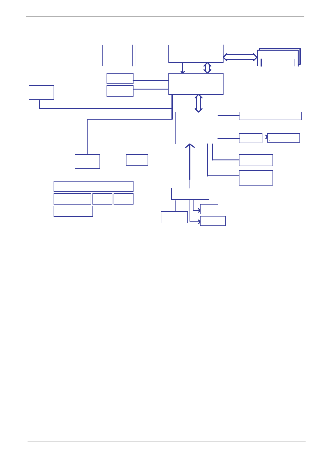
System Block Diagram
Mini card
Thermal Sensor
ADM1032ARM
CRT
LCD CONN
PCIE X1
PCIE X1
Realtek
RTL8102EL
Power On/Off CKT / LID switch / Power OK CKT
DC/DC Interface CKT.
LED
RTC CKT.
Power Circuit DC/DC
Clock Generator
ICS951462
RJ45 CONN
AMD AM2 CPU
940P PGA
H_A#(3..31) H_D#(0..63)
ATI-RS690MC
465 BGA
A-Link Express
4 x PCIE
ATI-SB600
549 BGA
page 18,19,20,21,22
LPC BUS
ENE KB926
Int. KBD
Touch Pad
CONN.
SPI BIOS
533/667
DDRII DDRII-SO-DIMM X2
Dual Channel
HT 16x16 1000MHZ
USB 2.0
HD Audio
SATA
SATA
SIG1 : 35mm x 35mm x (2.20mm+2.11mm) 638pin
AM2 : 40mm x 40mm x (4.56mm+2.11mm) 940pin
RS485 : 21mm x 21mm (19.2mm x 19.2mm) x2.33mm 465pin
RS690 : 21mm x 21mm (19.2mm x 19.2mm) x2.33mm 465pin
SB460 : 27mm x 27mm (21.6mm x 21.6mm) x2.33mm 549pin
SB600 : 23mm x 23mm (21.6mm x 21.6mm) x2.33mm 549pin
USB conn x 2 / Camera
HDA Codec
ALC268
HDD Conn.
CDROM Conn.
AMP & Audio Jack
APA2057
Chapter 1 3
Your Acer Notebook tour
After knowing your computer features, let us show you around your new computer.
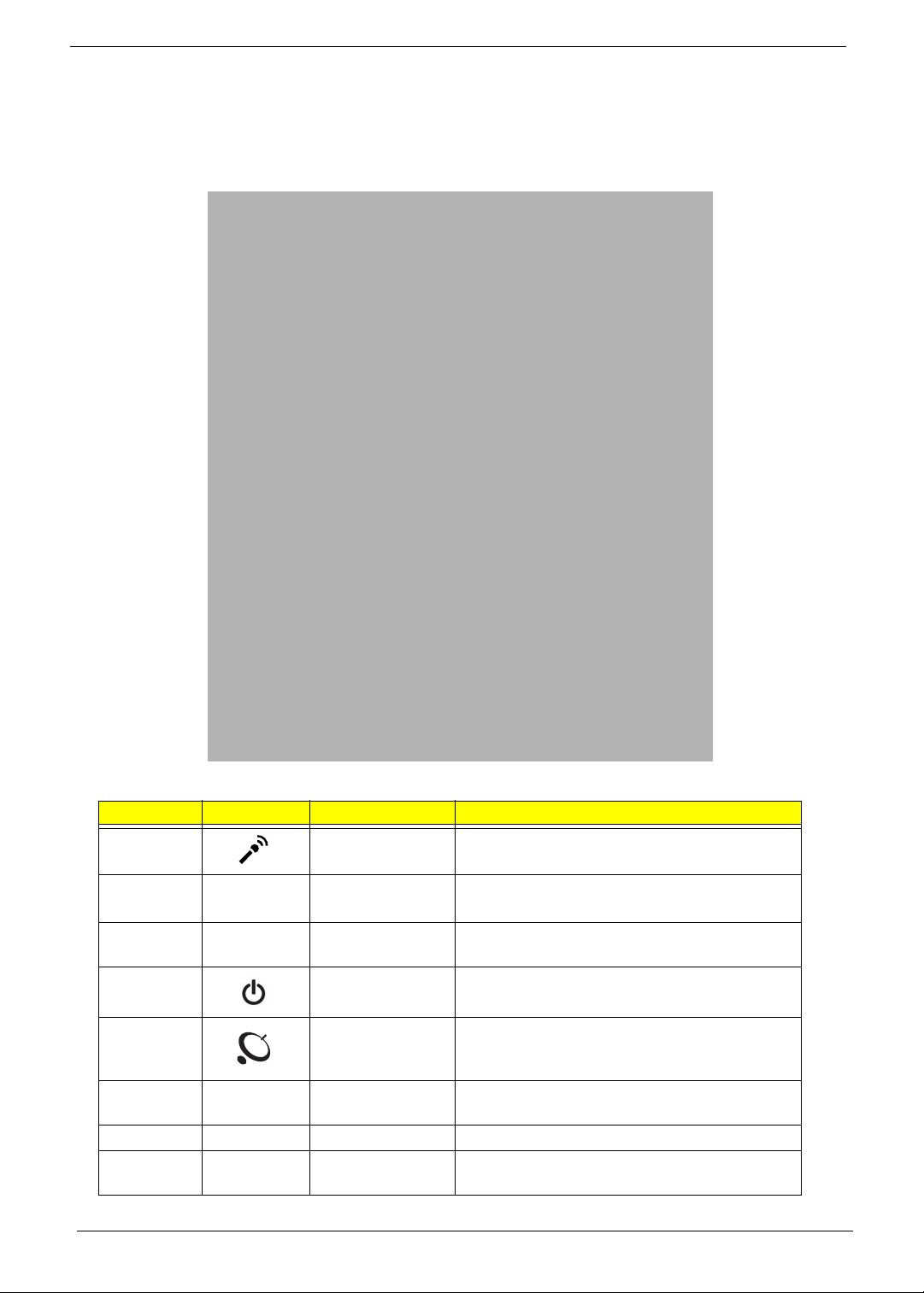
Front View
No. Icon Item Description
1 Microphone Internal microphone for sound recording.
2 Integrated
webcam
3 Display screen Also called Liquid-Crystal Display (LCD),
4 Power button Turns the computer on and off.
5 Wireless LAN
communication
button/indicator
6 Speakers Left and right speakers deliver stereo audio
7 Keyboard For entering data into your computer.
8 Palmrest Comfortable support area for your hands when
4 Chapter 1
Web camera for video communication
(for selected models).
displays computer output.
Enables/disables the wireless LAN function.
Indicates the status of wireless LAN
communication.
output.
you use the computer.
No. Icon Item Description
9 T ouchPad T ouch-sensitive pointing device which functions
like a computer mouse.
10 Click buttons (left
and right)
11 Power Indicates the computer's power status.
Battery Indicates the computer's battery status.
HDD Indicates when the hard disk drive is active.
Num Lock Lights up when Num Lock is activated.
Caps Lock Lights up when Caps Lock is activated.
NOTE: The Power and Battery indicators are visible even when the computer cover is closed
The left and right buttons function like the left
and right mouse buttons.
1. Charging: The light shows amber when the
battery is charging.
2. Fully charged: The light shows green when
in AC mode.
Closed Front View
No. Icon Item Description
1 Latch Locks and releases the lid
Rear View
No. Icon Item Description
1 Ventilation slots Enable the computer to stay cool, even after
prolonged use.
Chapter 1 5
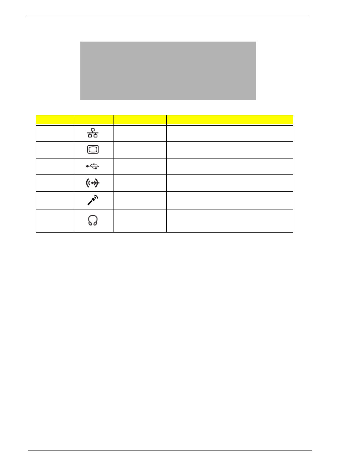
Left View
No. Icon Item Description
1 Ethernet (RJ-45)
port
2 External display
(VGA) port
3 USB 2.0 ports Connect to USB 2.0 devices (e.g. USB mouse,
Line-in jack Accepts audio line-in devices (e.g., audio CD
Microphone-in
jack
Connects to an Ethernet 10/100-based
network.
Connects to a display device
(e.g. external monitor, LCD projector).
USB camera).
player, stereo walkman, mp3 player).
Accepts input from external microphones.
Headphones/
speaker/line-out
jack
Connects to audio line-out devices
(e.g. speakers, headphones).
6 Chapter 1
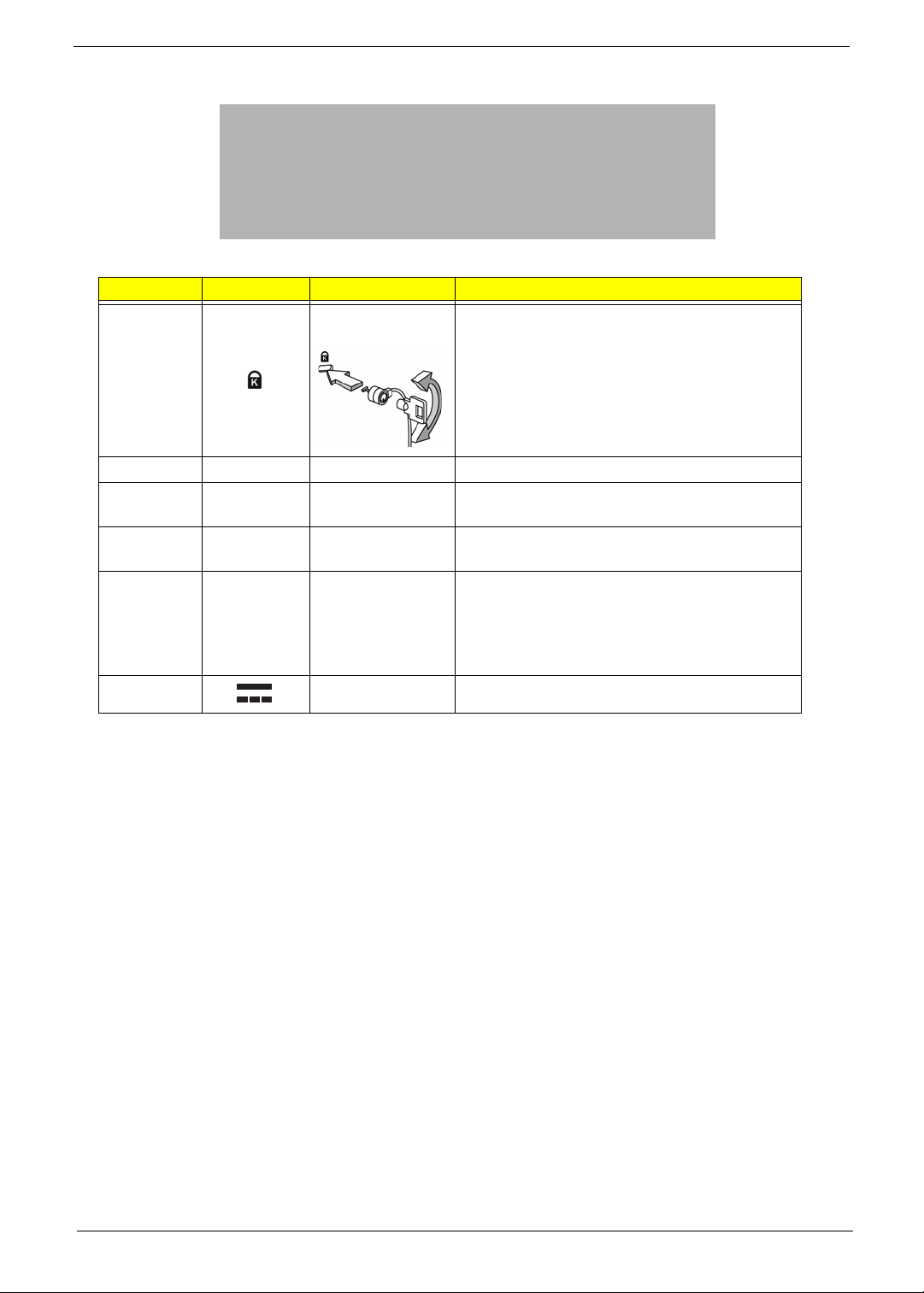
Right View
No. Icon Item Description
1 Kensington lock
slot
2 Optical drive Internal optical drive; accepts CDs or DVDs.
3 Optical disk access
indicator
4 Optical drive eject
button
5 Emergency eject
hole
8 DC-in jack Connects to an AC adapter
Connects to a Kensington-compatible computer
security lock.
Note: Wrap the computer security lock cable
around an immovable object such as a table or
handle of a locked drawer. Insert the lock into the
notch and turn the key to secure the lock.
Some keyless models are also available.
Lights up when the optical drive is active.
Ejects the optical disk from the drive.
Ejects the optical drive tray when the computer is
turned off.
Note: Insert a paper clip into the emergency eject
hole to eject the optical drive tray when the
computer is off.
Chapter 1 7
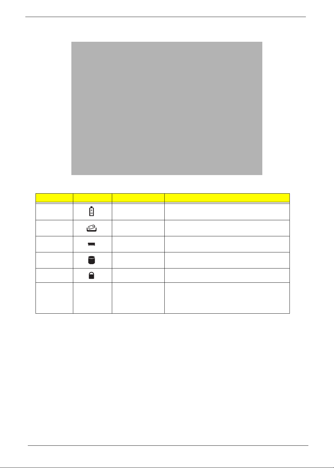
Bottom View
No. Icon Item Description
1 Battery bay Houses the computer's battery pack.
2 Battery release
latch
3 Memory
compartment
4 Hard disk bay Houses the computer's hard disk (secured with
5 Battery lock Locks the battery in position.
6 Ventilation slots
and cooling fan
Releases the battery for removal.
Houses the computer's main memory.
screws).
Enable the computer to stay cool, even after
prolonged use.
Note: Do not cover or obstruct the opening of the
fan.
8 Chapter 1
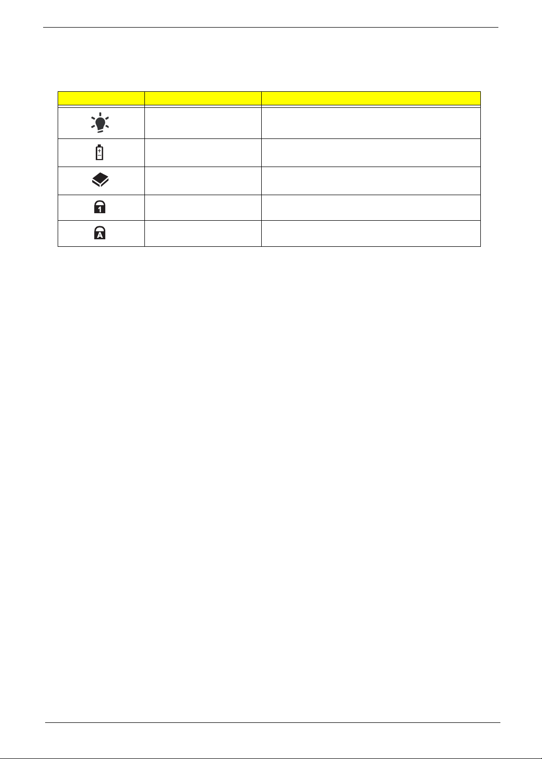
Indicators
The computer has several easy-to-read status indicators. The front panel indicators are visible even when the
computer cover is closed.
Icon Function Description
Power Indicates the computer's power status.
Battery Indicates the computer's battery status.
HDD Indicates when the hard disk drive is active.
Num Lock Lights up when Num Lock is activated.
Caps Lock Lights up when Caps Lock is activated.
NOTE: 1. Charging: The light shows amber when the battery is charging. 2. Fully charged: The light shows
green when in AC mode.
Chapter 1 9
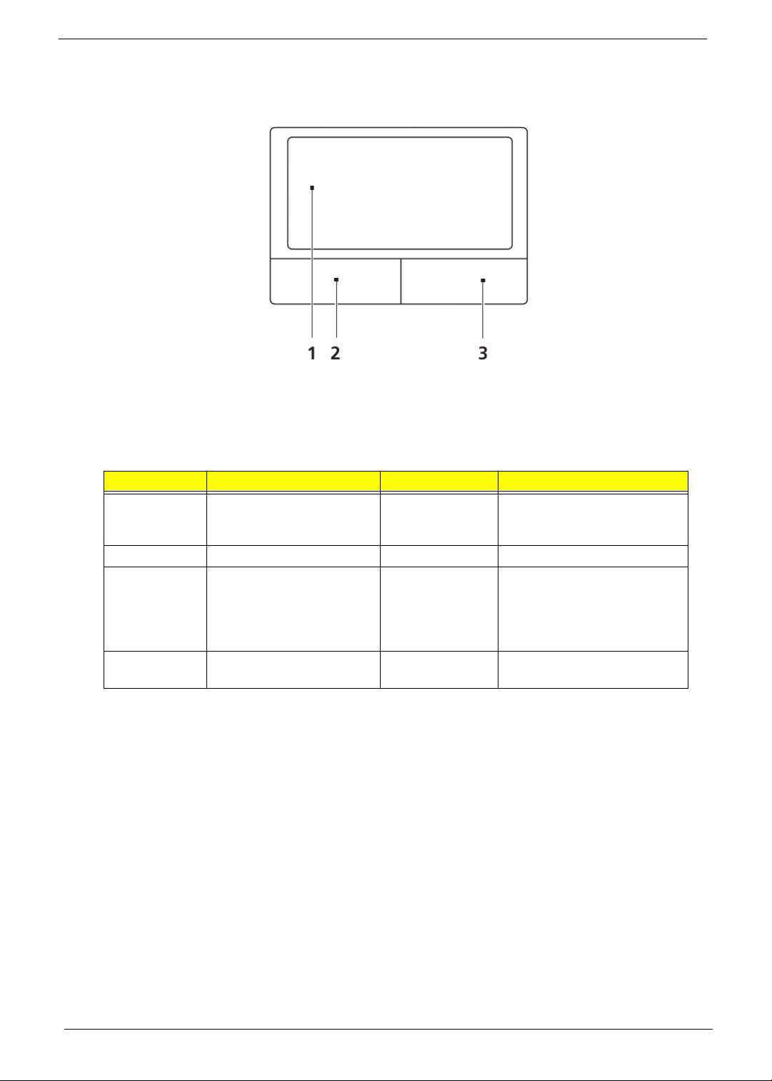
TouchPad Basics (with fingerprint reader)
The following items show you how to use the TouchPad with Acer Bio-Protection finge r p rint reader:
• Move your finger across the TouchPad (1) to move the cursor.
• Press the left (2) and right (3) buttons located beneath the TouchPad to perform selection and
execution functions. These two buttons are similar to the left and right buttons on a mouse.
Tapping on the TouchPad is the same as clicking the left button.
Function Left Button (2) Right Button (3) Main TouchPad (2)
Execute Quickly click twice. Tap twice (at the same speed
as double-clicking a mouse
button).
Select Click once. Tap once.
Drag Click and hold, then use
finger on the TouchPad to
drag the cursor.
Access
context menu
Click once.
Tap twice (at the same speed
as double-clicking a mouse
button); rest your finger on
the TouchPad on the second
tap and drag the cursor.
NOTE: When using the T ouchPad, keep it - and your fingers - dry and clean. The TouchPad is sensitive to
finger movement; hence, the lighter the touch, the better the response. Tapping too hard will not
increase the TouchPad’s responsiveness.
10 Chapter 1
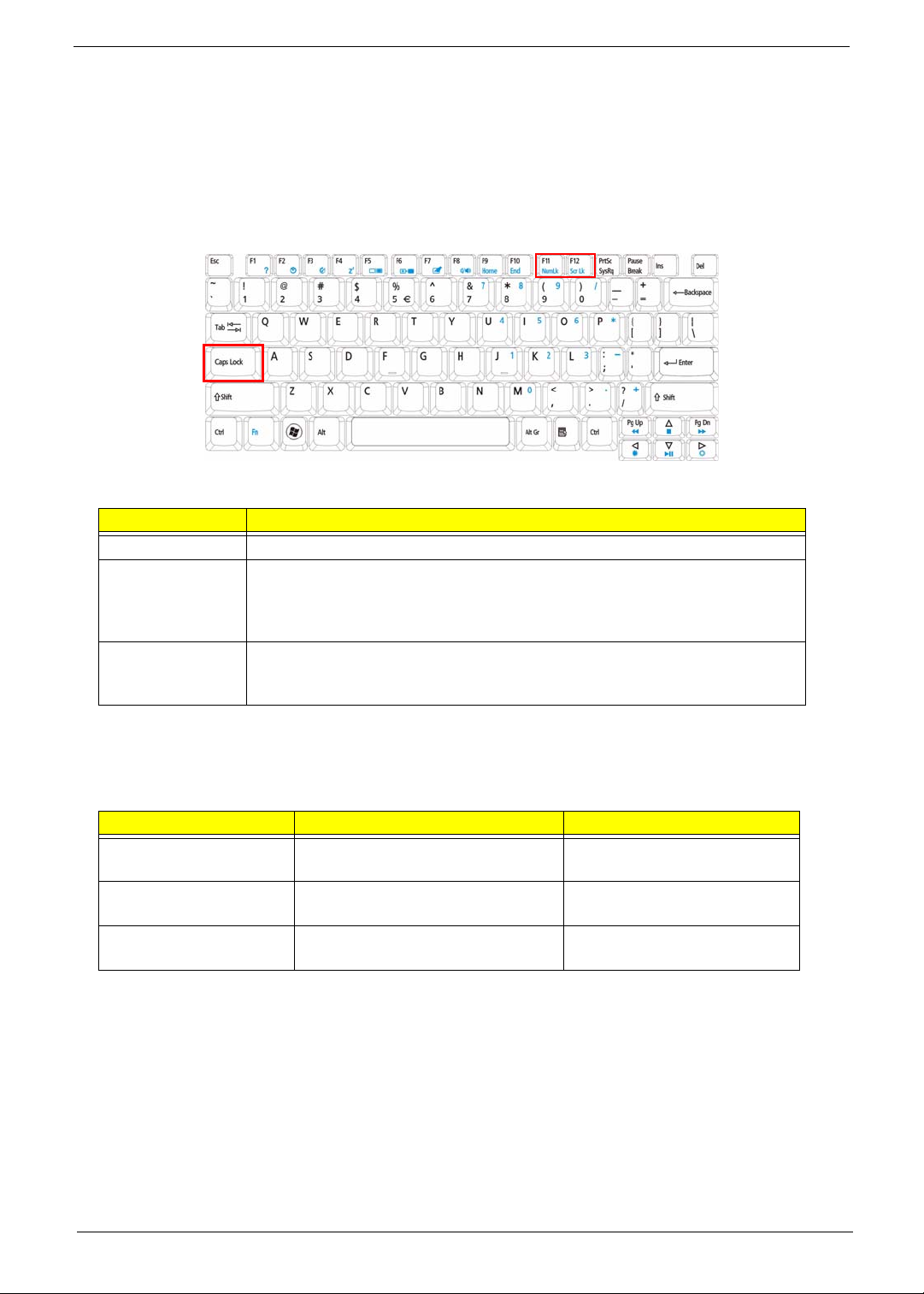
Using the Keyboard
The keyboard has full-sized keys and an embedded numeric keypad, separate cursor, lock, Windows, function
and special keys.
Lock Keys and embedded numeric keypad
The keyboard has three lock keys which you can toggle on and off.
Lock key Description
Caps Lock When Caps Lock is on, all alphabetic cha ra c ters typed are in uppercase.
Num Lock
<Fn> + <F11>
Scroll Lock <Fn> +
<F12>
When Num Lock is on, the embedded keypad is in numeric mode. The keys
function as a calculator (complete with the arithmetic operators +, -, *, and /). Use
this mode when you need to do a lot of numeric data entry. A better solution
would be to connect an external keypad.
When Scroll Lock is on, the screen moves one line up or down when you press
the up or down arrow keys respectively. Scroll Lock does not work with some
applications.
The embedded numeric keypad functions like a desktop numeric keypad. It is indicated by small characters
located on the upper right corner of the keycaps. To simplify the keyboard legend, cursor-control key symbols
are not printed on the keys.
Desired access Num Lock on Num Lock off
Number keys on
embedded keypad
Cursor-control keys on
embedded keypad
Main keyboard keys Hold <Fn> while typing letters on
Type numbers in a normal manner.
Hold <Shift> while using cursorcontrol keys.
embedded keypad.
Hold <Fn> while using cursorcontrol keys.
Type the letters in a normal
manner.
Chapter 1 11
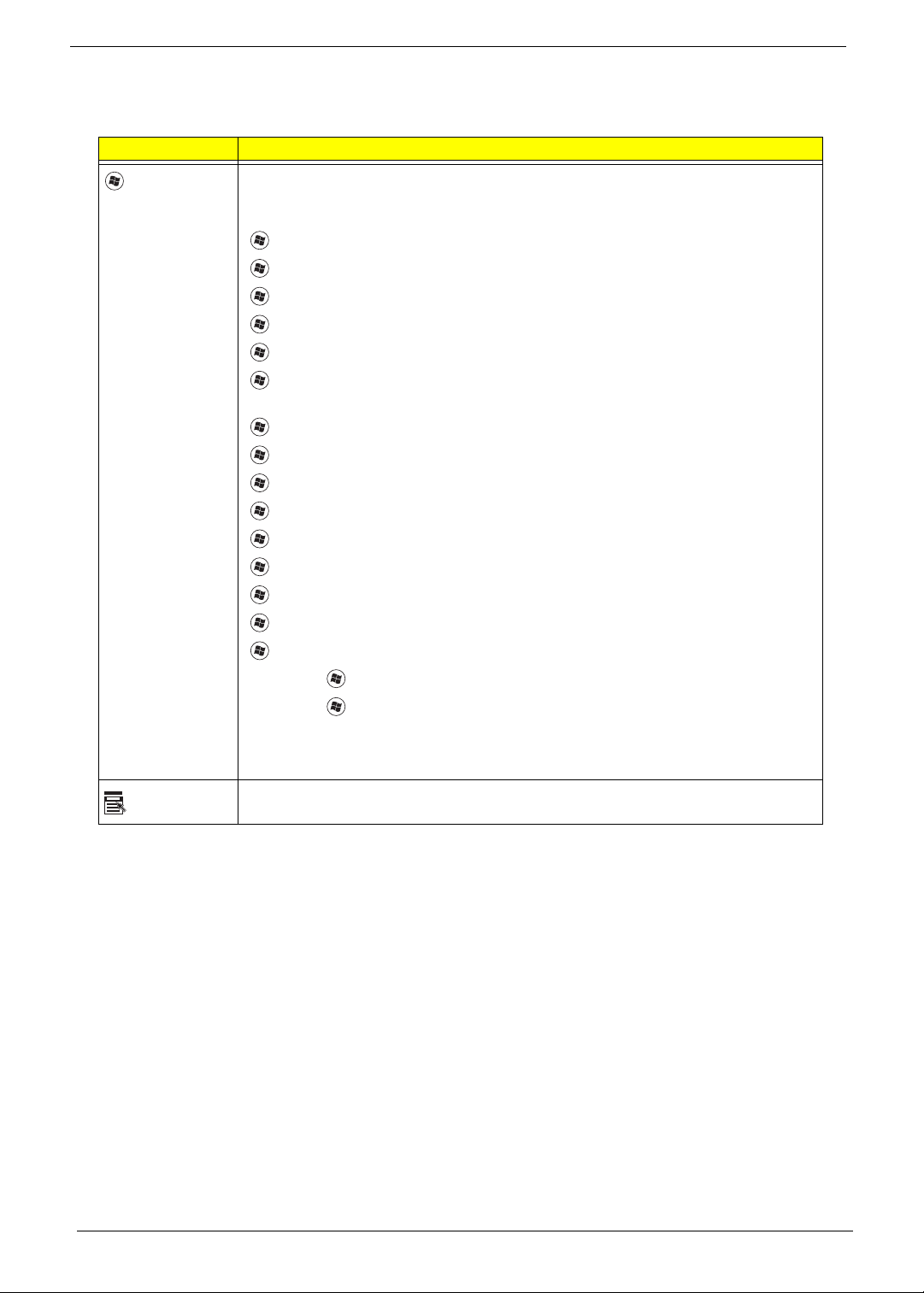
Windows Keys
The keyboard has two keys that perform Windows-specific functions.
Key Description
Windows key Pressed alone, this key has the same effect as clicking on the Windows Start button;
it launches the Start menu. It can also be used with other keys to provide a variety of
functions:
<>: Open or close the S tart menu
<> + <D>: Display the desktop
<> + <E>: Open Windows Explore
<> + <F>: Search for a file or folder
<> + <G>: Cycle through Sidebar gadgets
<> + <L>: Lock your computer (if you are connected to a network domain), or
switch users (if you're not connected to a network domain)
<> + <M>: Minimizes all windows
<> + <R>: Open the Run dialog box
<> + <T>: Cycle through programs on the taskbar
<> + <U>: Open Ease of Access Center
<> + <X>: Open Windows Mobility Center
<> + <BREAK>: Display the System Properties dialog box
<> + <SHIFT+M>: Restore minimized windows to the desktop
<> + <TAB>: Cycle through programs on the taskbar by using Windows Flip 3-D
<> + <SPACEBAR>: Bring all gadgets to the front and select Windows Sidebar
Application
key
<CTRL> +
<CTRL> + <> + <TAB>: Use the arrow keys to cycle through programs on the
Note: Depending on your edition of Windows Vista, some shortcuts may not function
This key has the same effect as clicking the right mouse button; it opens the
application's context menu.
<> + <F>: Search for computers (if you are on a network)
taskbar by using Windows Flip 3-D
as described.
12 Chapter 1
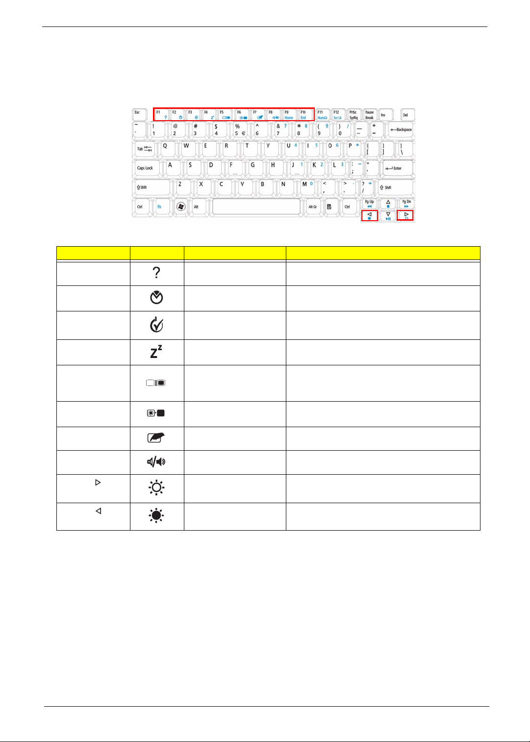
Hot Keys
The computer employs hotkeys or key combinations to access most of the computer’s controls like screen
brightness, volume output and the BIOS utility.
To activate hot keys, press and hold the <Fn> key before pressing the other key in the hotkey combination.
Hotkey Icon Function Description
<Fn> + <F1> Hotkey help Displays help on hotkeys.
<Fn> + <F2> Acer eSettings
Management
<Fn> + <F3> Acer ePower
Management
<Fn> + <F4> Sleep Puts the computer in Sleep mode.
<Fn> + <F5> Display toggle Switches display outp ut between the display
<Fn> + <F6> Screen blank Turns the display screen backlight off to save
<Fn> + <F7> TouchPad toggle Turns the internal TouchPad on and off.
<Fn> + <F8> Speaker toggle Turns the speakers on and off.
<Fn> + < > Brightness up Increases the screen brightness.
<Fn> + < > Brightness down Decreases the screen brightness.
Launches Acer eSettings Management in Acer
Empowering Technology.
Launches Acer ePower Management in Acer
Empowering Technology.
screen, external monitor (if connected) and
both.
power. Press any key to return.
Chapter 1 13
Special Key
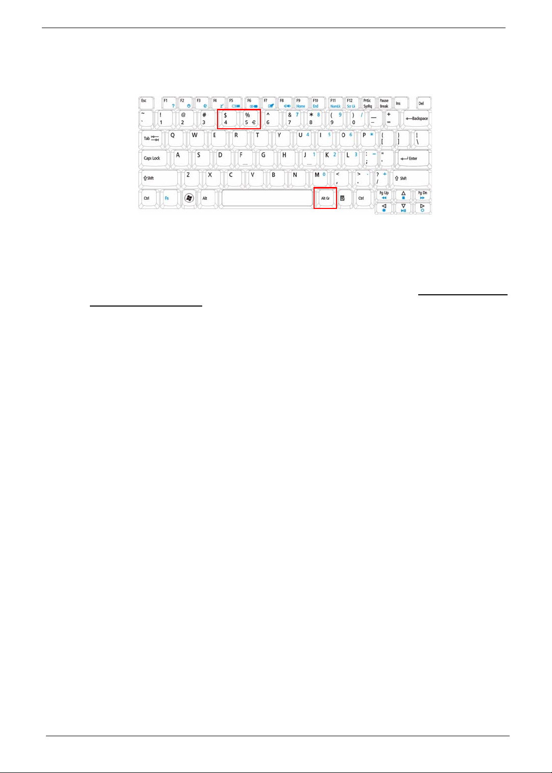
You can locate the Euro symbol and the US dollar sign at the upper-center and/or bottom-right of your
keyboard.
The Euro symbol
1. Open a text editor or word processor.
2. Hold <Alt Gr> and then press the <5> key at the upper-center of the keyboard.
NOTE: Note: Some fonts and software do not support the Euro symbol. Please refer to www.microsoft.com/
typography/faq/faq12.htm for more information.
The US dollar sign
1. Open a text editor or word processor.
2. Hold <Shift> and then press the <4> key at the upper-center of the keyboard.
NOTE: This function varies by the operating system version.
14 Chapter 1
Using the System Utilities
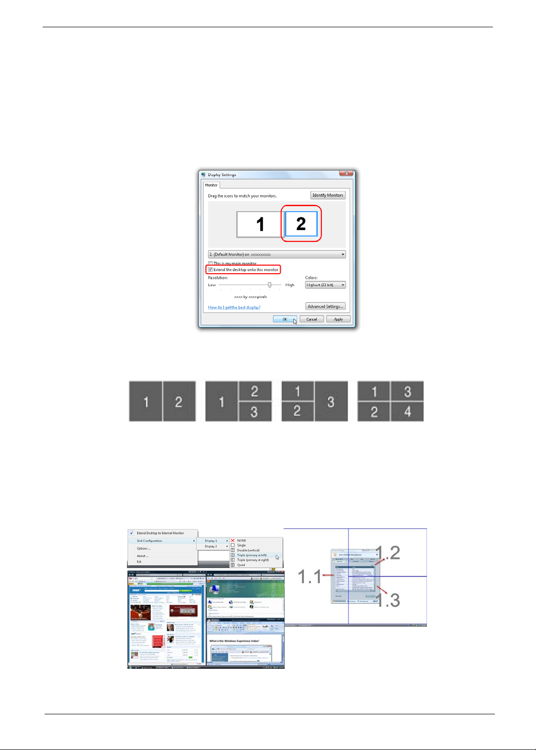
Acer GridVista (dual-display compatible)
NOTE: This feature is only available on certain models.
To enable the dual monitor feature of the notebook, first ensure that the second monitor is connected, then
select Start, Control Panel, Display and click on Settings. Select the secondary monitor (2) icon in the
display box and then click the check box Extend my windows desktop onto this monitor. Finally, click
Apply to confirm the new settings and click OK to complete the process.
Acer GridVista is a handy utility that offers four pre-defined display settings so you can view multiple windows
on the same screen. To access this function, please go to Start´ All Programs and click on Acer GridVista.
You may choose any one of the four display settings indicated below:
Double (vertical), Triple (primary at left), Triple (primary at right), or Quad Acer Gridvista is dual-display
compatible, allowing two displays to be partitioned independently.
Acer Gridvista is dual-display compatible, allowing two displays to be partitioned independently.
AcerGridVista is simple to set up:
1. Run Acer GridVista and select your preferred screen configuration for each display from the task bar.
2. Drag and drop each window into the appropriate grid.
3. Enjoy the convenience of a well-organized desktop.
NOTE: Please ensure that the resolution setting of the second monitor is set to the manufacturer's
recommended value.
Chapter 1 15
Hardware Specifications and Configurations
Processor
Item Specification
CPU type AMD Desktop Athlon, Socket AM2, 512KB catch, HyperTransport
I/F up to 1000 MHz
Core Logic
CPU Package AM2 PGA-940
CPU Fan True Value Table
CPU Temperature
Core 0 Core 1
•
BIOS
Item Specification
BIOS vendor PhoenixBIOS
BIOS Version V0.08
BIOS ROM type Flash
BIOS ROM size 1 MB
Supported protocols
BIOS password control Supervisor, User, and HDD0
• AMD RS690MC
• AMD SB600
Fan Speed (rpm) SPL Spec (dBA)
• Support ISIPP
• Support Acer UI
• Support multi-boot
• Suspend to RAM (S3)/Disk (S4)
• Va rious hot-keys for system control
• Support SMBIOS 2.3, PCI2.2
• ACPI 2.0 compliance with Intel Speed Step Support C1, C2, C3
and S3, S4 for desktop CPU
• DMI utility for BIOS serial number configurable/asset tag
• Support PXE
• Support Y2K solution
• Support Win Flash Wake on LAN from S3
• Wake on LAN form S4 in AC mode
• System information
16 Chapter 1
System Memory
Item Specification
Memory controller On Board
Memory size 0 MB
DIMM socket number 2
Supports memory size per socket 2 GB
Supports maximum memory size 4 GB
Supports DIMM type DDR SODIMM
Supports DIMM Speed DDR II 667/800 SDRAM
Supports DIMM voltage +1.8V
Cache 512KB cache on CPU
Features Adjustable 64/128/256MB UMA VGA memory share from North
Bridge
Memory Combinations
Slot 1 Slot 2 Total Memory
0MB 512MB 512MB
0MB 1024MB 1024MB
0MB 2048MB 2048MB
512MB 512MB 1024MB
512MB 1024MB 1536MB
512MB 2048MB 2560MB
1024MB 0MB 1024MB
1024MB 512MB 1536MB
1024MB 1024MB 2048MB
1024MB 2048MB 3072MB
2048MB 0MB 2048MB
2048MB 512MB 2560MB
2048MB 1024MB 3072MB
2048MB 2048MB 4096MB
NOTE: Above table lists some system memory configurations. You may combine DIMMs with various
capacities to form other combinations. On above table, the configuration of slot 1 and slot 2 could be
reversed.
LAN Interface
Item Specification
LAN Chipset Realtek RTL8102EL for 10/100 LAN
Supports LAN protocol
LAN connector type RJ-45
LAN connector location Left side
Features
Wireless Module 802.11b/g
Item Specification
Chipset
Data throughput
Protocol
Chapter 1 17
Item Specification
Interface
Hard Disk Drive Interface
Item Specification
Vendor Seagate Momentus 5400.4 SATA
Model Name ST9250827AS ST9160827AS ST9120817AS
Capacity (MB) 250 160 120
Bytes per sector 512
Data heads 4 3 2
Drive Format
Disks 2 2 1
Spindle speed (RPM) 5 ,400
Performance Specifications
Buffer size 8MB
Interface SATA
Internal transfer rate (Mbits/
sec max)
Sustained transfer rate
(Mbytes/sec max)
I/O data transfer rate
(Mbytes/sec max)
DC Power Requirements
Voltage tolerance 5V(DC) +/- 5%
778
58
300
Item Specification
Vendor Seagate Momentus 5400.5 SATA
Model Name ST9320320AS ST9250320AS ST9160310AS ST9120310AS
Capacity (MB) 320 250 160 120
Bytes per sector 512
Data heads 4 4 or 3 2 2
Drive Format
Disks 2 or 1 2 1 1
Spindle speed (RPM) 5,400
Performance Specifications
Buffer size 8 MB
Interface SATA
Internal transfer rate
(Mbits/sec max)
I/O data transfer rate
(Mbytes/sec max)
DC Power Requirements
Voltage tolerance 5V(DC) +/- 5%
352
150
18 Chapter 1
Super-Multi Drive Module
Item Specification
Vendor & model name HLDS/GSA-T50N, Philips DS-8A2S, Sony/AD-7560S, Toshiba Digi/TS-L633A
Performance S p ecification With CD Diskette With DVD Diskette
Transfer rate (MB/sec) Sustained:
Max 3.5 Mbytes/sec
Sustained:
Max 10 Mbytes/sec
Buffer Memory 2MB
Interface SATA
Applicable disc format Applicab le media types:
Writing:
Confirms to DVD+R Version 1.2 and DVD+RW Version 1.3 / DVD+R DL
Version 1.0 /DVD-R Version 2.0 / DVD-RW Version 1.2 / DVD-R DL Version
3.0.
Reading:
DVD single/dual layer (PTP, OTP), DVD-R single/dual layer
DVD+R single/double layer
DVD-RW
DVD+RW
CD-DA
CD-ROM
CD-ROM/XA
Photo-CD, Multi-session, Video CD
CD-I FMV, CD Extra, CD Plus, CD-R, and CD-RW
Loading mechanism Drawer (Solenoid Open)
Tact SW (Open)
Emergency Release (draw open hole)
Power Requirement
Input Voltage DC 5 V +/- 5%
Audio Interface
Item Specification
Audio Controller REALTEK ALC268 for High Definition Audio Codec
Mono or Stereo Stereo
Compatibility
• MIC IN
• AC-coupled input,100mVP-P maximum
• Headphone out
• 1VP-P
• 44.1/48/96/192kHz output
• Build-in Speaker
• 4CC 1.5W Speaker
System Board Major Chips
Item Controller
Core logic
• AMD RS690MC (1000MHz HT supported)
• AMD SB600
• Integrated VGA solution for RS690MC
LAN Realtek RTL8102EL for 10/100 LAN
Audio Codec REALTEK ALC268 for High Definition Audio Codec
Keyboard ENE KB926 for Keyboard Controller, Battery management Unit.
Chapter 1 19
Keyboard
Item Specification
Keyboard controller ENE KB926
Total number of keypads 87
Windows logo key Yes
Internal & external keyboard work
Yes
simultaneously
Battery
Item Specification
Vendor & model name SIMPLO
Battery Type Li-ion
Pack capacity
Number of battery cell
Package configuration
LCD 14.1”
Item Specification
Vendor/model name LG.Philips/LP141WX3, AUO/B141EW04 V4,
Chimei/N141I3 - L02, Samsung/LTN141W3-L01
Screen Diagonal (mm) 14.1 inches
Active Area (mm) 303.74 x 189.84 mm
Display resolution (pixels) 1280 x 800 WXGA
Pixel Pitch 0.2373 × 0.2373 mm
Pixel Arrangement R.G.B. Vertical Stripe
Display Mode Transmissive mode, normally white
2
200 cd/m2(Typ.5 point)
Typical White Luminance (cd/m
)
also called Brightness
Luminance Uniformity 1.3 max.
Contrast Ratio 300 minimum
Response Time (Optical Rise
16
Time/Fall Time) msec
Nominal Input Voltage VDD +3.3V
Typical Power Consumption (watt) 1.4W max.
Weight (without inverter) 400g max.
Physical Size (mm) 319.5 (±0.5) x 205.5 (± 0.5) x 5.5 max.
Electrical Interface 3.3V LVDS interface with 1 pixel/clock
Support Color g reater than 262144
Viewing Angle (degree)
Horizontal: Right/Left
Vertical: Upper/Lower
Minimum: 40/40, Typical: 45/45
Minimum: 10/30, Typical: 20/35
Temperature Range (°C)
Operating
Storage (shipping)
0 to +50
-20 to +60
20 Chapter 1
 Loading...