

Page 1

Aspire 4930/4930G Series
Service Guide
Service guide files and updates are available
on the ACER/CSD web; for more information,
please refer to http://csd.acer.com.tw
PRINTED IN TAIWAN
Page 2

Revision History
Please refer to the table below for the updates made on Aspire 4930 Series service guide.
Date Chapter Updates
II
Page 3

Copyright
Copyright © 2008 by Acer Incorporated. All rights reserved. No part of this publication may be reproduced,
transmitted, transcribed, stored in a retrieval system, or translated into any language or computer language, in
any form or by any means, electronic, mechanical, magnetic, optical, chemical, manual or otherwise, without
the prior written permission of Acer Incorporated.
Disclaimer
The information in this guide is subject to change without notice.
Acer Incorporated makes no representations or warranties, either expressed or implied, with respect to the
contents hereof and specifically disclaims any warranties of merchantability or fitness for any particular
purpose. Any Acer Incorporated software described in this manual is sold or licensed "as is". Should the
programs prove defective following their purchase, the buyer (and not Acer Incorporated, its distributor, or its
dealer) assumes the entire cost of all necessary servicing, repair, and any incidental or consequential
damages resulting from any defect in the software.
Acer is a registered trademark of Acer Corporation.
Intel is a registered trademark of Intel Corporation.
Pentium and Pentium II/III are trademarks of Intel Corporation.
Other brand and product names are trademarks and/or registered trademarks of their respective holders.
III
Page 4

Conventions
The following conventions are used in this manual:
SCREEN MESSAGES Denotes actual messages that appear
on screen.
NOTE Gives bits and pieces of additional
information related to the current
topic.
WARNING Alerts you to any damage that might
result from doing or not doing specific
actions.
CAUTION Gives precautionary measures to
avoid possible hardware or software
problems.
IMPORTANT Reminds you to do specific actions
relevant to the accomplishment of
procedures.
IV
Page 5

Preface
Before using this information and the product it supports, please read the following general information.
1. This Service Guide provides you with all technical information relating to the BASIC CONFIGURATION
decided for Acer's "global" product offering. To better fit local market requirements and enhance product
competitiveness, your regional office MAY have decided to extend the functionality of a machine (e.g.
add-on card, modem, or extra memory capability). These LOCALIZED FEATURES will NOT be covered
in this generic service guide. In such cases, please contact your regional offices or the responsible
personnel/channel to provide you with further technical details.
2. Please note WHEN ORDERING FRU PARTS, that you should check the most up-to-date information
available on your regional web or channel. If, for whatever reason, a part number change is made, it will
not be noted in the printed Service Guide. For ACER-AUTHORIZED SERVICE PROVIDERS, your Acer
office may have a DIFFERENT part number code to those given in the FRU list of this printed Service
Guide. You MUST use the list provided by your regional Acer office to order FRU parts for repair and
service of customer machines.
V
Page 6

VI
Page 7

Table of Contents
System Specifications 1
Features . . . . . . . . . . . . . . . . . . . . . . . . . . . . . . . . . . . . . . . . . . . . . . . . . . . . . . . . . . . .1
System Block Diagram . . . . . . . . . . . . . . . . . . . . . . . . . . . . . . . . . . . . . . . . . . . . . . . . .4
Your Acer Notebook tour . . . . . . . . . . . . . . . . . . . . . . . . . . . . . . . . . . . . . . . . . . . . . . .5
Front View . . . . . . . . . . . . . . . . . . . . . . . . . . . . . . . . . . . . . . . . . . . . . . . . . . . . . . .5
Closed Front View . . . . . . . . . . . . . . . . . . . . . . . . . . . . . . . . . . . . . . . . . . . . . . . . .6
Left View . . . . . . . . . . . . . . . . . . . . . . . . . . . . . . . . . . . . . . . . . . . . . . . . . . . . . . . .7
Right View . . . . . . . . . . . . . . . . . . . . . . . . . . . . . . . . . . . . . . . . . . . . . . . . . . . . . . .8
Rear View . . . . . . . . . . . . . . . . . . . . . . . . . . . . . . . . . . . . . . . . . . . . . . . . . . . . . . .8
Bottom View . . . . . . . . . . . . . . . . . . . . . . . . . . . . . . . . . . . . . . . . . . . . . . . . . . . . .9
Indicators . . . . . . . . . . . . . . . . . . . . . . . . . . . . . . . . . . . . . . . . . . . . . . . . . . . . . .10
Easy-Launch Buttons . . . . . . . . . . . . . . . . . . . . . . . . . . . . . . . . . . . . . . . . . . . . .11
Touch Pad Basics (with fingerprint reader) . . . . . . . . . . . . . . . . . . . . . . . . . . . . .12
Using the Keyboard . . . . . . . . . . . . . . . . . . . . . . . . . . . . . . . . . . . . . . . . . . . . . . . . . .13
Lock Keys and embedded numeric keypad . . . . . . . . . . . . . . . . . . . . . . . . . . . .13
Windows Keys . . . . . . . . . . . . . . . . . . . . . . . . . . . . . . . . . . . . . . . . . . . . . . . . . .14
Hot Keys . . . . . . . . . . . . . . . . . . . . . . . . . . . . . . . . . . . . . . . . . . . . . . . . . . . . . . .15
Special Key . . . . . . . . . . . . . . . . . . . . . . . . . . . . . . . . . . . . . . . . . . . . . . . . . . . . .16
Acer Empowering Technology . . . . . . . . . . . . . . . . . . . . . . . . . . . . . . . . . . . . . . . . . .17
Empowering Technology password . . . . . . . . . . . . . . . . . . . . . . . . . . . . . . . . . .17
Acer eNet Management . . . . . . . . . . . . . . . . . . . . . . . . . . . . . . . . . . . . . . . . . . .18
Acer ePower Management . . . . . . . . . . . . . . . . . . . . . . . . . . . . . . . . . . . . . . . .19
Acer eAudio Management . . . . . . . . . . . . . . . . . . . . . . . . . . . . . . . . . . . . . . . . .21
Acer ePresentation Management . . . . . . . . . . . . . . . . . . . . . . . . . . . . . . . . . . .22
Acer eDataSecurity Management (for selected models) . . . . . . . . . . . . . . . . . .23
Acer eLock Management . . . . . . . . . . . . . . . . . . . . . . . . . . . . . . . . . . . . . . . . . .24
Acer eRecovery Management . . . . . . . . . . . . . . . . . . . . . . . . . . . . . . . . . . . . . .25
Acer eSettings Management . . . . . . . . . . . . . . . . . . . . . . . . . . . . . . . . . . . . . . .26
Windows Mobility Center . . . . . . . . . . . . . . . . . . . . . . . . . . . . . . . . . . . . . . . . . .27
Using the System Utilities . . . . . . . . . . . . . . . . . . . . . . . . . . . . . . . . . . . . . . . . . . . . . .28
Acer GridVista (dual-display compatible) . . . . . . . . . . . . . . . . . . . . . . . . . . . . . .28
Launch Manager . . . . . . . . . . . . . . . . . . . . . . . . . . . . . . . . . . . . . . . . . . . . . . . . .29
Norton Internet Security . . . . . . . . . . . . . . . . . . . . . . . . . . . . . . . . . . . . . . . . . . .30
Hardware Specifications and Configurations . . . . . . . . . . . . . . . . . . . . . . . . . . . . . . .31
System Utilities 39
BIOS Setup Utility . . . . . . . . . . . . . . . . . . . . . . . . . . . . . . . . . . . . . . . . . . . . . . . . . . . .39
Navigating the BIOS Utility . . . . . . . . . . . . . . . . . . . . . . . . . . . . . . . . . . . . . . . . .39
Information . . . . . . . . . . . . . . . . . . . . . . . . . . . . . . . . . . . . . . . . . . . . . . . . . . . . .40
Main . . . . . . . . . . . . . . . . . . . . . . . . . . . . . . . . . . . . . . . . . . . . . . . . . . . . . . . . . .41
Advanced . . . . . . . . . . . . . . . . . . . . . . . . . . . . . . . . . . . . . . . . . . . . . . . . . . . . . .42
Security . . . . . . . . . . . . . . . . . . . . . . . . . . . . . . . . . . . . . . . . . . . . . . . . . . . . . . . .44
Power . . . . . . . . . . . . . . . . . . . . . . . . . . . . . . . . . . . . . . . . . . . . . . . . . . . . . . . . .47
Boot . . . . . . . . . . . . . . . . . . . . . . . . . . . . . . . . . . . . . . . . . . . . . . . . . . . . . . . . . . .49
Exit . . . . . . . . . . . . . . . . . . . . . . . . . . . . . . . . . . . . . . . . . . . . . . . . . . . . . . . . . . .50
BIOS Flash Utility . . . . . . . . . . . . . . . . . . . . . . . . . . . . . . . . . . . . . . . . . . . . . . . . . . . .51
Remove HDD/BIOS Utility . . . . . . . . . . . . . . . . . . . . . . . . . . . . . . . . . . . . . . . . . . . . .52
Machine Disassembly and Replacement 57
Disassembly Requirements . . . . . . . . . . . . . . . . . . . . . . . . . . . . . . . . . . . . . . . . . . . .57
General Information . . . . . . . . . . . . . . . . . . . . . . . . . . . . . . . . . . . . . . . . . . . . . . . . . .58
Pre-disassembly Instructions . . . . . . . . . . . . . . . . . . . . . . . . . . . . . . . . . . . . . . .58
Disassembly Process . . . . . . . . . . . . . . . . . . . . . . . . . . . . . . . . . . . . . . . . . . . . .58
External Module Disassembly Process . . . . . . . . . . . . . . . . . . . . . . . . . . . . . . . . . . .59
VII
Page 8

Table of Contents
External Modules Disassembly Flowchart . . . . . . . . . . . . . . . . . . . . . . . . . . . . .59
Removing the Battery Pack . . . . . . . . . . . . . . . . . . . . . . . . . . . . . . . . . . . . . . . .60
Removing the SD dummy card . . . . . . . . . . . . . . . . . . . . . . . . . . . . . . . . . . . . . .61
Removing the ExpressCard dummy card . . . . . . . . . . . . . . . . . . . . . . . . . . . . . .62
Removing the Lower Covers . . . . . . . . . . . . . . . . . . . . . . . . . . . . . . . . . . . . . . . .63
Removing the DIMM Module . . . . . . . . . . . . . . . . . . . . . . . . . . . . . . . . . . . . . . .65
Removing the WLAN Board Module . . . . . . . . . . . . . . . . . . . . . . . . . . . . . . . . . .66
Removing the Hard Disk Drive Module . . . . . . . . . . . . . . . . . . . . . . . . . . . . . . . .68
Removing the Optical Drive Module . . . . . . . . . . . . . . . . . . . . . . . . . . . . . . . . . .70
Main Unit Disassembly Process . . . . . . . . . . . . . . . . . . . . . . . . . . . . . . . . . . . . . . . . .73
Main Unit Disassembly Flowchart . . . . . . . . . . . . . . . . . . . . . . . . . . . . . . . . . . . .73
Removing the Switch Cover . . . . . . . . . . . . . . . . . . . . . . . . . . . . . . . . . . . . . . . .74
Removing the Keyboard . . . . . . . . . . . . . . . . . . . . . . . . . . . . . . . . . . . . . . . . . . .76
Removing the Antenna . . . . . . . . . . . . . . . . . . . . . . . . . . . . . . . . . . . . . . . . . . . .78
Removing the LCD Module . . . . . . . . . . . . . . . . . . . . . . . . . . . . . . . . . . . . . . . . .82
Removing the Upper Cover . . . . . . . . . . . . . . . . . . . . . . . . . . . . . . . . . . . . . . . .84
Removing the Touch Pad Bracket . . . . . . . . . . . . . . . . . . . . . . . . . . . . . . . . . . .88
Removing the Finger Print Reader . . . . . . . . . . . . . . . . . . . . . . . . . . . . . . . . . . .91
Removing the Launch Board . . . . . . . . . . . . . . . . . . . . . . . . . . . . . . . . . . . . . . .93
Removing the Speaker Module . . . . . . . . . . . . . . . . . . . . . . . . . . . . . . . . . . . . . .95
Removing the Switch Board . . . . . . . . . . . . . . . . . . . . . . . . . . . . . . . . . . . . . . . .97
Removing the Touch Pad Board . . . . . . . . . . . . . . . . . . . . . . . . . . . . . . . . . . . . .98
Removing the I/O Board . . . . . . . . . . . . . . . . . . . . . . . . . . . . . . . . . . . . . . . . . . .99
Removing the Bluetooth board . . . . . . . . . . . . . . . . . . . . . . . . . . . . . . . . . . . . .101
Removing the Modem Module . . . . . . . . . . . . . . . . . . . . . . . . . . . . . . . . . . . . .103
Removing the Main Board . . . . . . . . . . . . . . . . . . . . . . . . . . . . . . . . . . . . . . . .106
Removing the Thermal Module . . . . . . . . . . . . . . . . . . . . . . . . . . . . . . . . . . . . .110
Removing the CPU . . . . . . . . . . . . . . . . . . . . . . . . . . . . . . . . . . . . . . . . . . . . . .112
Removing the CPU Fan . . . . . . . . . . . . . . . . . . . . . . . . . . . . . . . . . . . . . . . . . .114
Removing the HDMI Module . . . . . . . . . . . . . . . . . . . . . . . . . . . . . . . . . . . . . . .116
LCD Module Disassembly Process . . . . . . . . . . . . . . . . . . . . . . . . . . . . . . . . . . . . .118
LCD Module Disassembly Flowchart . . . . . . . . . . . . . . . . . . . . . . . . . . . . . . . .118
Removing the LCD Bezel . . . . . . . . . . . . . . . . . . . . . . . . . . . . . . . . . . . . . . . . .119
Removing the Inverter Board . . . . . . . . . . . . . . . . . . . . . . . . . . . . . . . . . . . . . .121
Removing the Camera Module . . . . . . . . . . . . . . . . . . . . . . . . . . . . . . . . . . . . .123
Removing the LCD Panel . . . . . . . . . . . . . . . . . . . . . . . . . . . . . . . . . . . . . . . . .125
Removing the LCD Brackets and FPC Cable . . . . . . . . . . . . . . . . . . . . . . . . . .126
Removing the Antennas . . . . . . . . . . . . . . . . . . . . . . . . . . . . . . . . . . . . . . . . . .129
Removing the MIC Module . . . . . . . . . . . . . . . . . . . . . . . . . . . . . . . . . . . . . . . .131
LCM Module Reassembly Procedure . . . . . . . . . . . . . . . . . . . . . . . . . . . . . . . . . . . .132
Replacing the LCD Panel . . . . . . . . . . . . . . . . . . . . . . . . . . . . . . . . . . . . . . . . .132
Replacing the LCM Bezel . . . . . . . . . . . . . . . . . . . . . . . . . . . . . . . . . . . . . . . . .134
Main Module Reassembly Procedure . . . . . . . . . . . . . . . . . . . . . . . . . . . . . . . . . . . .135
Replacing the CPU . . . . . . . . . . . . . . . . . . . . . . . . . . . . . . . . . . . . . . . . . . . . . .135
Replacing the Thermal Module . . . . . . . . . . . . . . . . . . . . . . . . . . . . . . . . . . . . .135
Replacing the CPU Fan Module . . . . . . . . . . . . . . . . . . . . . . . . . . . . . . . . . . . .136
Replacing the HDMI Module . . . . . . . . . . . . . . . . . . . . . . . . . . . . . . . . . . . . . . .136
Replacing the Mainboard . . . . . . . . . . . . . . . . . . . . . . . . . . . . . . . . . . . . . . . . .137
Replacing the I/O Board . . . . . . . . . . . . . . . . . . . . . . . . . . . . . . . . . . . . . . . . . .138
Replacing the Bluetooth Board . . . . . . . . . . . . . . . . . . . . . . . . . . . . . . . . . . . . .138
Replacing the Modem Module . . . . . . . . . . . . . . . . . . . . . . . . . . . . . . . . . . . . .139
Replacing the Finger Print Reader . . . . . . . . . . . . . . . . . . . . . . . . . . . . . . . . . .140
Replacing the Touch Pad . . . . . . . . . . . . . . . . . . . . . . . . . . . . . . . . . . . . . . . . .141
Replacing the Launch Board . . . . . . . . . . . . . . . . . . . . . . . . . . . . . . . . . . . . . . .142
Replacing the Switch Board . . . . . . . . . . . . . . . . . . . . . . . . . . . . . . . . . . . . . . .142
VIII
Page 9

Table of Contents
Replacing the Antenna Cables . . . . . . . . . . . . . . . . . . . . . . . . . . . . . . . . . . . . .143
Replacing the Speaker Module . . . . . . . . . . . . . . . . . . . . . . . . . . . . . . . . . . . . .144
Replacing the Keyboard . . . . . . . . . . . . . . . . . . . . . . . . . . . . . . . . . . . . . . . . . .144
Replacing the Switch Cover . . . . . . . . . . . . . . . . . . . . . . . . . . . . . . . . . . . . . . .145
Replacing the WLAN Module . . . . . . . . . . . . . . . . . . . . . . . . . . . . . . . . . . . . . .145
Replacing the Hard Disk Drive Module . . . . . . . . . . . . . . . . . . . . . . . . . . . . . . .146
Replacing the DIMM Modules . . . . . . . . . . . . . . . . . . . . . . . . . . . . . . . . . . . . . .147
Replacing the ODD Module . . . . . . . . . . . . . . . . . . . . . . . . . . . . . . . . . . . . . . .148
Replacing the Lower Covers . . . . . . . . . . . . . . . . . . . . . . . . . . . . . . . . . . . . . . .148
Replacing the Express and SD Card Trays . . . . . . . . . . . . . . . . . . . . . . . . . . .149
Troubleshooting 151
Common Problems . . . . . . . . . . . . . . . . . . . . . . . . . . . . . . . . . . . . . . . . . . . . . . . . . .151
Power On Issue . . . . . . . . . . . . . . . . . . . . . . . . . . . . . . . . . . . . . . . . . . . . . . . .152
No Display Issue . . . . . . . . . . . . . . . . . . . . . . . . . . . . . . . . . . . . . . . . . . . . . . . .153
Random Loss of BIOS Settings . . . . . . . . . . . . . . . . . . . . . . . . . . . . . . . . . . . .154
LCD Failure . . . . . . . . . . . . . . . . . . . . . . . . . . . . . . . . . . . . . . . . . . . . . . . . . . . .155
Built-In Keyboard Failure . . . . . . . . . . . . . . . . . . . . . . . . . . . . . . . . . . . . . . . . .155
Touch Pad Failure . . . . . . . . . . . . . . . . . . . . . . . . . . . . . . . . . . . . . . . . . . . . . . .156
Internal Speaker Failure . . . . . . . . . . . . . . . . . . . . . . . . . . . . . . . . . . . . . . . . . .156
Internal Microphone Failure . . . . . . . . . . . . . . . . . . . . . . . . . . . . . . . . . . . . . . .158
HDD Not Operating Correctly . . . . . . . . . . . . . . . . . . . . . . . . . . . . . . . . . . . . . .159
ODD Failure . . . . . . . . . . . . . . . . . . . . . . . . . . . . . . . . . . . . . . . . . . . . . . . . . . .160
USB Failure (Rightside) . . . . . . . . . . . . . . . . . . . . . . . . . . . . . . . . . . . . . . . . . .163
Modem Function Failure . . . . . . . . . . . . . . . . . . . . . . . . . . . . . . . . . . . . . . . . . .163
Wireless Function Failure . . . . . . . . . . . . . . . . . . . . . . . . . . . . . . . . . . . . . . . . .164
EasyTouch Button Failure . . . . . . . . . . . . . . . . . . . . . . . . . . . . . . . . . . . . . . . . .164
MediaTouch Button Failure . . . . . . . . . . . . . . . . . . . . . . . . . . . . . . . . . . . . . . . .165
Fingerprint Reader Failure . . . . . . . . . . . . . . . . . . . . . . . . . . . . . . . . . . . . . . . .165
Thermal Unit Failure . . . . . . . . . . . . . . . . . . . . . . . . . . . . . . . . . . . . . . . . . . . . .166
HDTV Switch Failure . . . . . . . . . . . . . . . . . . . . . . . . . . . . . . . . . . . . . . . . . . . . .166
External Mouse Failure . . . . . . . . . . . . . . . . . . . . . . . . . . . . . . . . . . . . . . . . . . .167
Other Failures . . . . . . . . . . . . . . . . . . . . . . . . . . . . . . . . . . . . . . . . . . . . . . . . . .167
Intermittent Problems . . . . . . . . . . . . . . . . . . . . . . . . . . . . . . . . . . . . . . . . . . . . . . . .168
Undetermined Problems . . . . . . . . . . . . . . . . . . . . . . . . . . . . . . . . . . . . . . . . . . . . . .168
Jumper and Connector Locations 169
Top View . . . . . . . . . . . . . . . . . . . . . . . . . . . . . . . . . . . . . . . . . . . . . . . . . . . . . . . . . .169
Bottom View . . . . . . . . . . . . . . . . . . . . . . . . . . . . . . . . . . . . . . . . . . . . . . . . . . . . . . .170
Clearing Password Check and BIOS Recovery . . . . . . . . . . . . . . . . . . . . . . . . . . . .171
Clearing Password Check . . . . . . . . . . . . . . . . . . . . . . . . . . . . . . . . . . . . . . . . .171
BIOS Recovery by Crisis Disk . . . . . . . . . . . . . . . . . . . . . . . . . . . . . . . . . . . . .172
FRU (Field Replaceable Unit) List 173
Aspire 4930 Exploded Diagram . . . . . . . . . . . . . . . . . . . . . . . . . . . . . . . . . . . . . . . .174
Model Definition and Configuration 182
Aspire 4930 Series . . . . . . . . . . . . . . . . . . . . . . . . . . . . . . . . . . . . . . . . . . . . . . . . . .182
Test Compatible Components 205
Microsoft® Windows® Vista Environment Test . . . . . . . . . . . . . . . . . . . . . . . . . . . .206
Online Support Information 209
Index 211
IX
Page 10

Table of Contents
X
Page 11

System Specifications
Features
Below is a brief summary of the computer’s many feature:
Operating System
• Windows® Vista™
Platform
• Intel® Centrino® 2 processor technology, featuring:
• Intel® Core™2 Duo processor*
• Mobile Intel® PM45/GM45 Express Chipset*
• Intel® Wireless WiFi Link 5100/5300, 5150/5350*
System Memory
Chapter 1
• Dual-Channel DDR2 SDRAM support
• Up to 2 GB of DDR2 667 MHz memory, upgradeable to 4 GB using two soDIMM modules*
TV Tuner
• Digital TV-tuner supporting DVB-T*
Display and graphics
• 14.1" WXGA 1280 x 800
• Mobile Intel® GM45 Express Chipset
• NVIDIA GeForce 9300M GS / 9600M GT (For Aspire 4390G only)
Storage subsystem
• 2.5" hard disk drive
• Optical drive options:
• Blu-ray Disc™ /DVD-Super Multi double-layerdrive
• DVD-Super Multi double-layer drive
• 5-in-1 card reader
Audio
• Dolby-certified surround sound system with two built-in stereo speakers and one subwoofer
supporting low-frequency effects
• S/PDIF (Sony/Philips Digital Interface) support for digital speakers
• Acer PureZone technology with two built-in stereo microphones
Chapter 1 1
Page 12

Dimensions and Weight
• 340.4 (W) x 247 (D) x 22.9/42.3 (H) mm (13.4 x 9.7 x 0.9/1.6 inches)
• 2.4 kg (5.29 lbs.)
Communication
• Acer Video Conference, featuring:
• Integrated Acer Crystal Eye webcam
• Acer Video Conference Manager software
• Acer PureZone technology
• Optional Acer Xpress VoIP phone
• WLAN: Intel® Wireless WiFi Link 5100/5300*
• WiFi®/WiMAX™: Intel® Wireless WiFi Link 5150/5350*
• WPAN: Bluetooth® 2.0+EDR (Enhanced Data Rate)
• LAN: Gigabit Ethernet; Wake-on-LAN ready
• Modem: 56K ITU V.92
Privacy control
• Acer Bio-Protection fingerprint solution
• BIOS user, supervisor, HDD passwords
• Kensington lock slot
Power subsystem
• ACPI 3.0
• 48.8 W 4400 mAh*
• 3-pin 90 W AC adapter*
• 3-pin 65 W AC adapter*
• Energy Star 4.0
Special keys and controls
• 88-/89-/93-key keyboard
• Touch Pad pointing de vi ce
• Empowering Key
• Easy-launch buttons: WLAN, Internet, email, Bluetooth, Acer Arcade™
• Acer MediaTouch keys: play/pause, stop, previous, next and record keys
• Volume wheel
• Acer Media Center remote control*
I/O interface
• Acer EasyPort IV connector
• ExpressCard™/54 slot
• 5-in-1 card reader (SD/MMC/MS/MS PRO/xD)
2 Chapter 1
Page 13

• 3 USB 2.0 ports
• HDMI™ port with HDCP support
• Consumer infrared (CIR) port
• External display (VGA) port
• Headphones/speaker/line-out port with S/PDIF support
• Microphone-in jack
• Line-in jack
• Ethernet (RJ-45) port
• Modem (RJ-11) port
• DC-in jack for AC adapter
Environment
• Temperature:
• Operating: 5 °C to 35 °C
• Non-operating: -20 °C to 65 °C
• Humidity (non-condensing):
• Operating: 20% to 80%
• Non-operating: 20% to 80%
NOTE: Items marked with * denote only selected models.
Chapter 1 3
Page 14
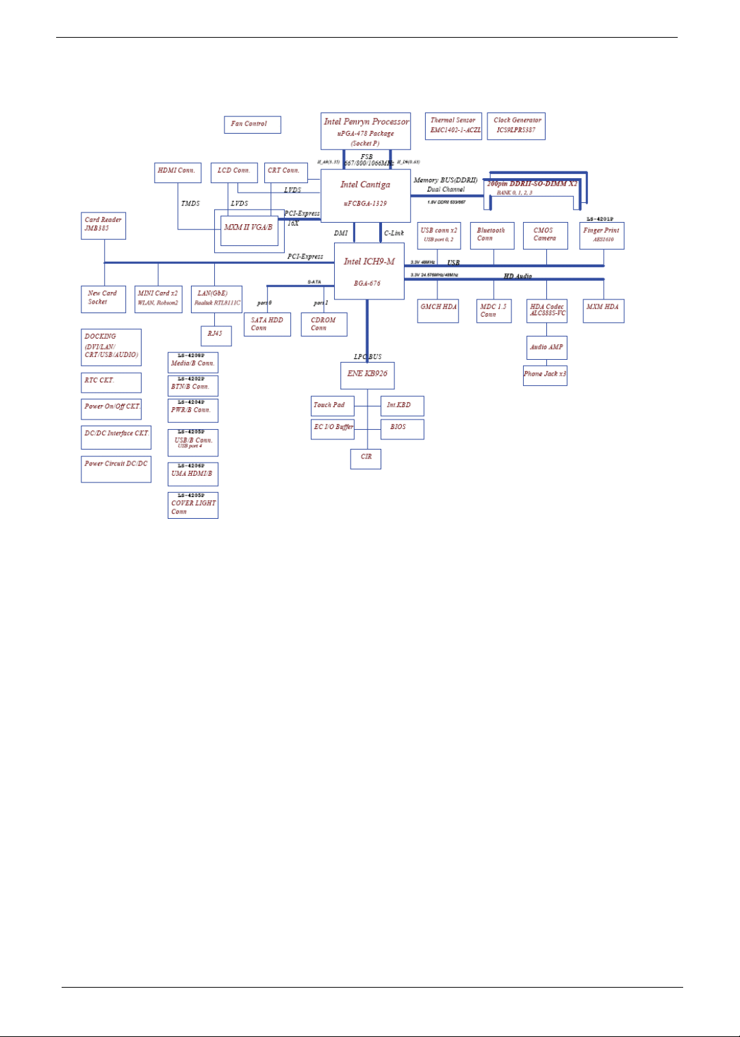
System Block Diagram
4 Chapter 1
Page 15
Your Acer Notebook tour
After knowing your computer features, let us show you around your new computer.
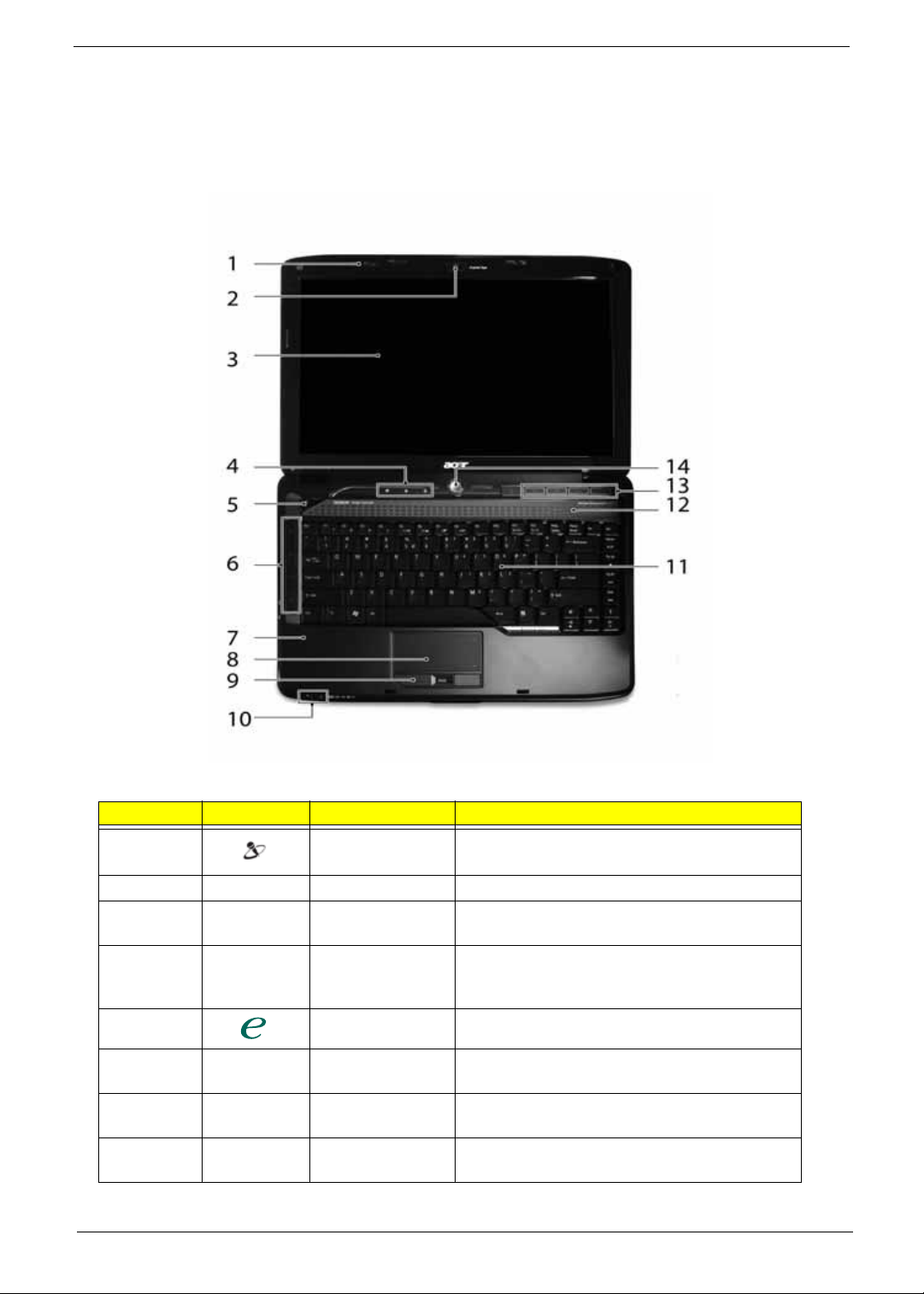
Front View
No. Icon Item Description
1 Acer PureZone Two internal stereo microphones for sound
recording.
2 Acer Crystal Eye Web camera for video communication.
3 Display screen Also called Liquid-Crystal Display (LCD),
displays computer output.
4 Status indicators Light-Emitting Diodes (LEDs) that light up to
show the status of the computer's functions
and components.
5 Empowering key Launch Acer Empowering Technol ogy
6 Easy-launch
buttons
7 Palmrest Comfortable support area for your hands when
8 T ouch Pad T ouch-sensitive pointing device which functions
Chapter 1 5
Buttons for launching frequently used program.
you use the computer.
like a computer mouse.
Page 16
No. Icon Item Description
9 Click buttons
(left, center* and
right)
10 Status indicators Light-Emitting Diodes (LEDs) that light up to
11 Keyboard For entering data into your computer.
12 Speakers Left and right speakers deliver stereo audio
13 Acer MediaT ouch
keys
14 Power button Turns the computer on and off.
The left and right buttons function like the left
and right mouse buttons. *The center button
serves as Acer Bio-Protection fingerprint
reader supporting Acer FingerNav 4-way
control function.
show the status of the computer's functions
and components.
output.
For use with Acer Arcade and other media
playing programs.
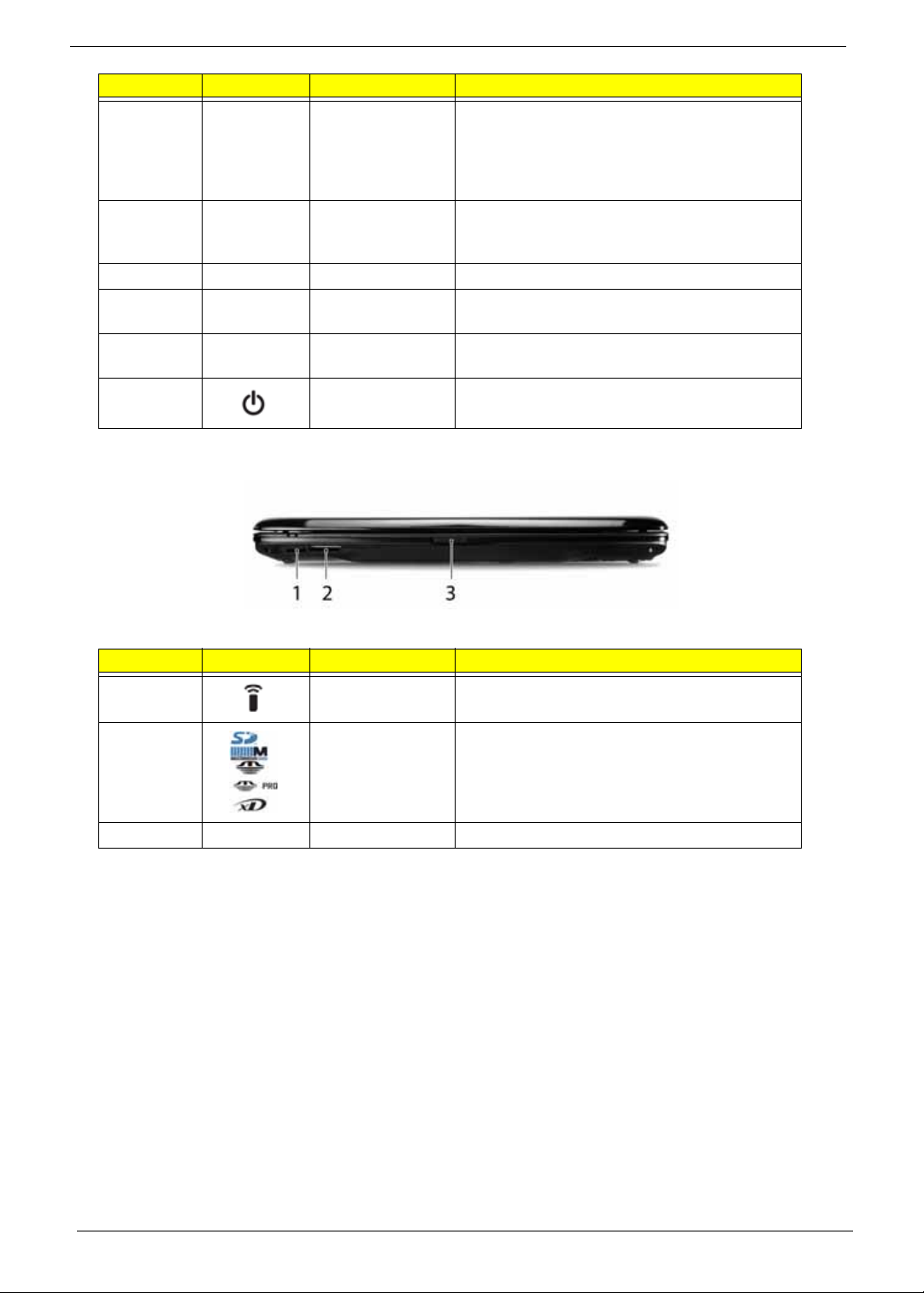
Closed Front View
No. Icon Item Description
1 CIR receiver Receives signals from a remote control.
2 5-in-1 card
reader
3 Latch Locks and releases the lid
Accepts Secure Digital (SD), MultiMediaCard
(MMC), Memory Stick (MS), Memory Stick
PRO (MS PRO), xD-Picture Card (xD).
6 Chapter 1
Page 17
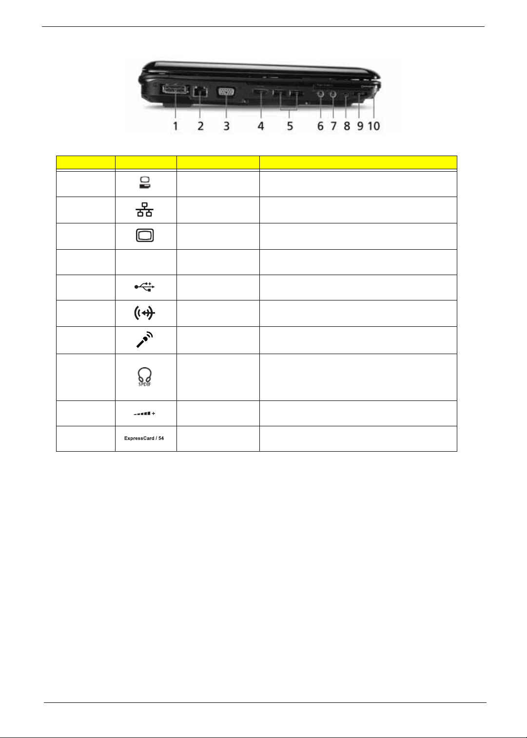
Left View
No. Icon Item Description
1 Acer EasyPort IV
connector
2 Ethernet (RJ-45)
port
3 External display
(VGA) port
4
5 USB 2.0 ports Connect to USB 2.0 devices (e.g. USB mouse,
6 Line-in jack Accepts audio line-in devices (e.g. audio CD
7 Microphone-in
HDMI
HDMI Connects to a television or display device with
jack
Connects to Acer EasyPort IV.
Connects to an Ethernet 10/100/1000-based
network.
Connects to a display device
(e.g. external monitor, LCD projector).
HDMI input.
USB camera).
player, stereo walkman).
Accepts input from external microphones.
8 Headphones/
speaker/line-out
jack with S/PDIF
support
9 Unlimited volume
control wheel
10 ExpressCard/54
slot
Connects to audio line-out devices
(e.g. speakers, headphones).
Adjust the volume of the audio-out.
Accepts one ExpressCard/54 module.
Chapter 1 7
Page 18
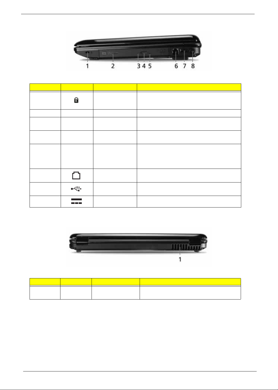
Right View
No. Icon Item Description
1 Kensington lock
slot
2 Optical drive Internal optical drive; accepts CDs or DVDs.
3 Optical disk access
indicator
4 Optical drive eject
button
5 Emergency eject
hole
6 Modem (RJ-11)
port
7 USB 2.0 port Connect to USB 2.0 devices (e.g. USB mouse,
8 DC-in jack Connects to an AC adapter
Connects to a Kensington-compatible computer
security lock.
Lights up when the optical drive is active.
Ejects the optical disk from the drive.
Ejects the optical drive tray when the computer is
turned off. Note: Insert a paper clip into the
emergency eject hole to eject the optical drive
tray when the computer is off.
Connects to a phone line.
USB camera).
Rear View
No. Icon Item Description
1 Ventilation slots Enable the computer to stay cool, even after
prolonged use.
8 Chapter 1
Page 19
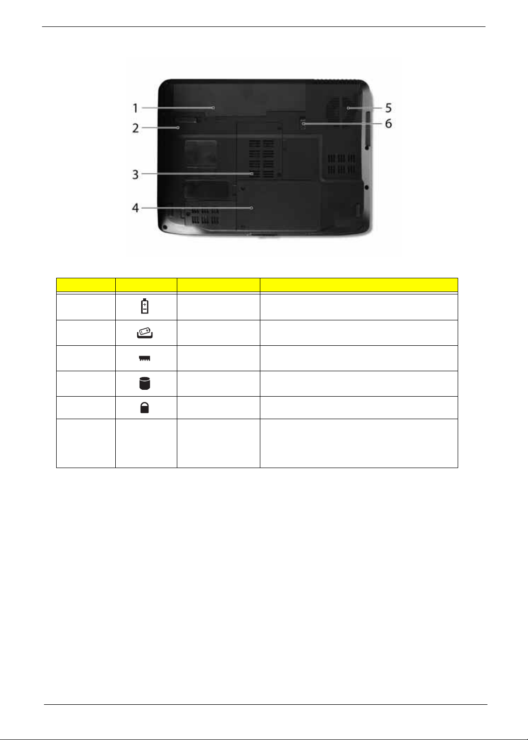
Bottom View
No. Icon Item Description
1 Battery bay Houses the computer's battery pack.
2 Battery release
latch
3 Memory
compartment
4 Hard disk bay Houses the computer's hard disk (secured with
5 Battery lock Locks the battery in position.
6 Ventilation slots
and cooling fan
Releases the battery for removal.
Houses the computer's main memory.
screws).
Enable the computer to stay cool, even after
prolonged use.
Note: Do not cover or obstruct the opening of the
fan.
Chapter 1 9
Page 20
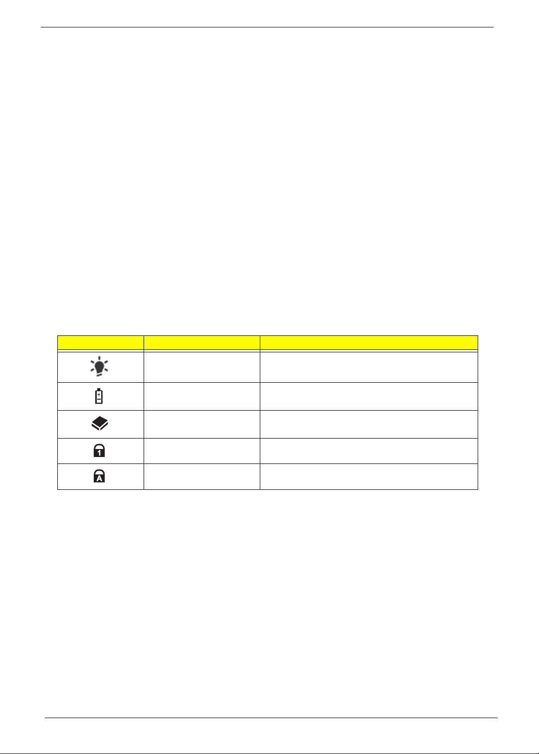
Indicators
The computer has several easy-to-read status indicators:
The front panel indicators are visible even when the computer cover is closed.
Icon Function Description
Power Indicates the computer's power status.
Battery Indicates the computer's battery status.
HDD Indicates when the hard disk drive is active.
Num Lock Lights up when Num Lock is activated.
Caps Lock Lights up when Caps Lock is activated.
NOTE: 1. Charging: The light shows amber when the battery is charging. 2. Fully charged: The light shows
green when in AC mode.
10 Chapter 1
Page 21
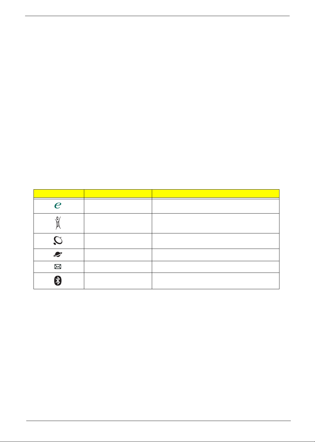
Easy-Launch Buttons
Located beside the keyboard are application buttons. These buttons are called easy-launch buttons. They are:
WLAN, Internet, email, Bluetooth, Arcade and Acer Empowering Technology.
The mail and Web browser buttons are pre-set to email and Internet programs, but can be reset by users. To
set the Web browser, mail and programmable buttons, run the Acer Launch Manager.
Icon Function Description
Empowering Technology Launch Acer Empowering Technology.
(user-programmable)
Acer Arcade Launch Acer Arcade utility
Wireless communication
button/indicator
Web browser Internet browser (user-Programmable)
Mail Email application (user-Programmable)
Bluetooth communication
button/indicator
Enables/disables the wireless function. Indicates
the status of wireless LAN communication.
Enables/disables the Bluetooth function. Indicates
the status of Bluetooth communication.
Chapter 1 11
Page 22
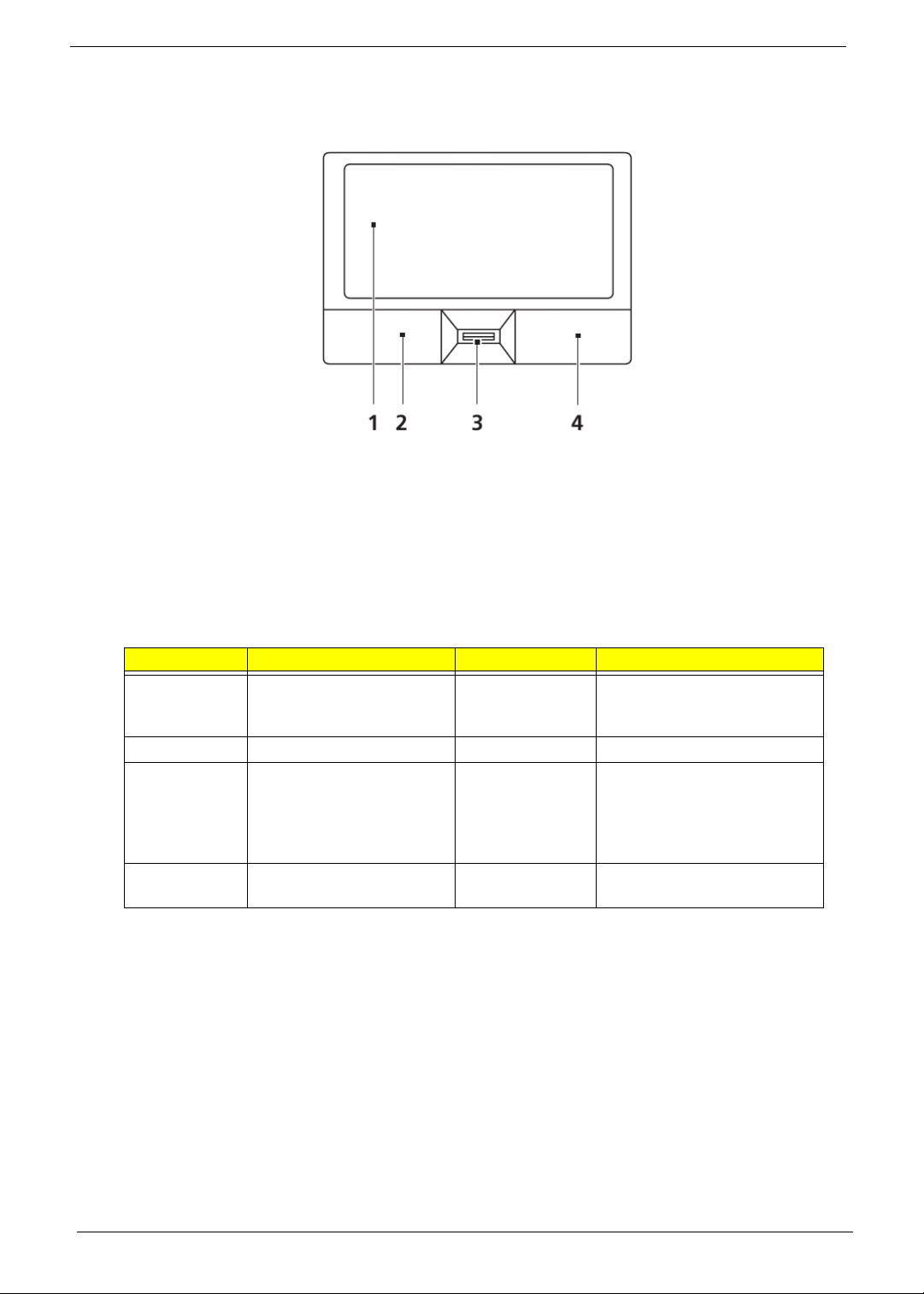
Touch Pad Basics (with fingerprint reader)
The following items show you how to use the Touch Pad with Acer Bio-Protection fingerprint reader:
• Move your finger across the Touch Pad (2) to move the cursor.
• Press the left (1) and right (4) buttons located beneath the Touch Pad to perform selection and
execution functions. These two buttons are similar to the left and right buttons on a mouse.
Tapping on the Touch Pad is the same as clicking the left button.
• Use Acer Bio-Protection fingerprint reader (3) supporting Acer FingerNav 4-way control function
(only for certain models) or the 4-way scroll (3) button (only for certain models) to scroll up or down
and move left or right a page. This fingerprint reader or button mimics your cursor pressing on the
right scroll bar of Windows applications.
Function Left Button (1) Right Button (3) Main Touch Pad (2)
Execute Quickly click twice. Tap twice (at the same speed
as double-clicking a mouse
button).
Select Click once. Tap once.
Drag Click and hold, then use
finger on the Touch Pad to
drag the cursor.
Tap twice (at the same speed
as double-clicking a mouse
button); rest your finger on
the Touch Pad on the second
tap and drag the cursor.
Access
Click once.
context menu
NOTE: When using the Touch Pad, keep it - and your fingers - dry and clean. The Touch Pad is sensitive to
finger movement; hence, the lighter the touch, the better the response. Tapping too hard will not
increase the Touch Pad’s responsiveness.
12 Chapter 1
Page 23
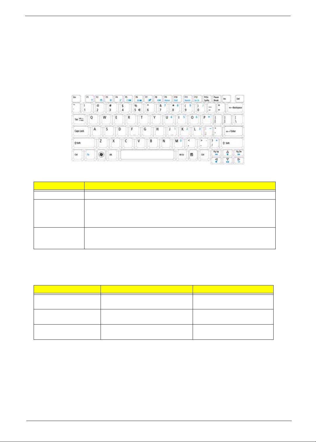
Using the Keyboard
The keyboard has full-sized keys and an embedded numeric keypad, separate cursor, lock, Windows, function
and special keys.
Lock Keys and embedded numeric keypad
The keyboard has three lock keys which you can toggle on and off.
Lock key Description
Caps Lock When Caps Lock is on, all alphabetic charac ters typed are in uppercase.
Num Lock
<Fn> + <F11>
Scroll Lock <Fn> +
<F12>
When Num Lock is on, the embedded keypad is in numeric mode. The keys
function as a calculator (complete with the arithmetic operators +, -, *, and /). Use
this mode when you need to do a lot of numeric data entry. A better solution
would be to connect an external keypad.
When Scroll Lock is on, the screen moves one line up or down when you press
the up or down arrow keys respectively. Scroll Lock does not work with some
applications.
The embedded numeric keypad functions like a desktop numeric keypad. It is indicated by small characters
located on the upper right corner of the keycaps. To simplify the keyboard legend, cursor-control key symbols
are not printed on the keys.
Desired access Num Lock on Num Lock off
Number keys on
embedded keypad
Cursor-control keys on
embedded keypad
Main keyboard keys Hold <Fn> while typing letters on
Type numbers in a normal manner.
Hold <Shift> while using cursorcontrol keys.
embedded keypad.
Hold <Fn> while using cursorcontrol keys.
Type the letters in a normal
manner.
Chapter 1 13
Page 24
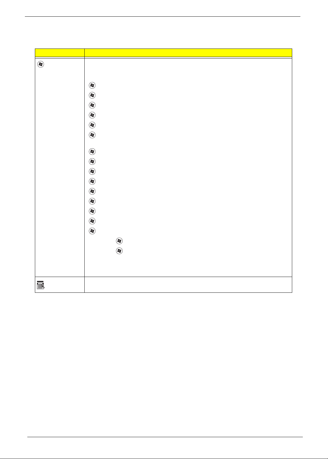
Windows Keys
The keyboard has two keys that perform Windows-specific functions.
Key Description
Windows key Pressed alone, this key has the same effect as clicking on the Windows Start button;
it launches the Start menu. It can also be used with other keys to provide a variety of
functions:
<> : Open or close the Start menu
<> + <D>: Display the desktop
<> + <E>: Open Windows Explore
<> + <F>: Search for a file or folder
<> + <G>: Cycle through Sidebar gadgets
<> + <L>: Lock your computer (if you are connected to a network domain), or
switch users (if you're not connected to a network domain)
<> + <M>: Minimizes all windows
<> + <R>: Open the Run dialog box
<> + <T>: Cycle through programs on the taskbar
<> + <U>: Open Ease of Access Center
<> + <X>: Open Windows Mobility Center
<> + <BREAK>: Display the System Properties dialog box
<> + <SHIFT+M>: Restore minimized windows to the desktop
<> + <TAB>: Cycle through programs on the taskbar by using Windows Flip 3-D
<> + <SPACEBAR>: Bring all gadgets to the front and select Windows Sidebar
Application
key
<CTRL> +
<CTRL> + <> + <TAB>: Use the arrow keys to cycle through programs on the
Note: Depending on your edition of Windows Vista, some shortcuts may not function
This key has the same effect as clicking the right mouse button; it opens the
application's context menu.
<> + <F>: Search for computers (if you are on a network)
taskbar by using Windows Flip 3-D
as described.
14 Chapter 1
Page 25
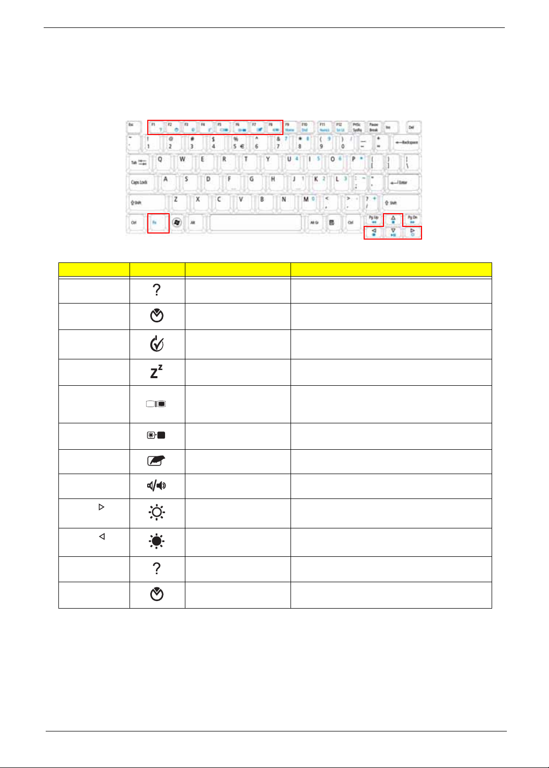
Hot Keys
The computer employs hotkeys or key combinations to access most of the computer’s controls like screen
brightness, volume output and the BIOS utility.
To activate hot keys, press and hold the <Fn> key before pressing the other key in the hotkey combination.
Hotkey Icon Function Description
<Fn> + <F1> Hotkey help Displays help on hotkeys.
<Fn> + <F2> Acer eSettings
Management
<Fn> + <F3> Acer ePower
Management
<Fn> + <F4> Sleep Puts the computer in Sleep mode.
<Fn> + <F5> Display toggle Switches display output between the display
<Fn> + <F6> Screen blank Turns the display screen backlight off to save
<Fn> + <F7> Touch Pad toggle Turns the internal Touch Pad on and off.
<Fn> + <F8> Speaker toggle Turns the speakers on and off.
<Fn> + < > Brightness up Increases the screen brightness.
<Fn> + < > Brightness down Decreases the screen brightness.
<Fn> + <F1> Hotkey help Displays help on hotkeys.
<Fn> + <F2> Acer eSettings
Management
Launches Acer eSettings Management in Acer
Empowering Technology.
Launches Acer ePower Management in Acer
Empowering Technology.
screen, external monitor (if connected) and
both.
power. Press any key to return.
Launches Acer eSettings Management in Acer
Empowering Technology.
Chapter 1 15
Page 26
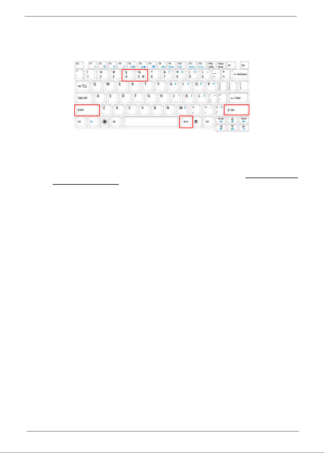
Special Key
You can locate the Euro symbol and the US dollar sign at the upper-center and/or bottom-right of your
keyboard.
The Euro symbol
1. Open a text editor or word processor.
2. Hold <Alt Gr> and then press the <5> key at the upper-center of the keyboard.
NOTE: Note: Some fonts and software do not support the Euro symbol. Please refer to www.microsoft.com/
typography/faq/faq12.htm for more information.
The US dollar sign
1. Open a text editor or word processor.
2. Hold <Shift> and then press the <4> key at the upper-center of the keyboard.
NOTE: This function varies by the operating system version.
16 Chapter 1
Page 27

Acer Empowering Technology
The Empowering Technology toolbar makes it easy for you to access frequently used functions and manage
your new Acer system. Displayed by default in the upper half of your screen, it provides access to the following
utilities:
• Acer eNet Management hooks up to location-based networks intelligently.
• Acer ePower Management optimizes battery usage via customizable power plans.
• Acer ePresenta tion Management connects to a projector and adjusts display settings.
• Acer eDataSecurity Management protects data with passwords and encryption.
• Acer eLock Management limits access to external storage media.
• Acer eRecovery Management backs up and recovers data flexibly, reliably and completely.
• Acer eSettings Management accesses system information and adjusts settings easily.
For more information, right click on the Empowering Technology toolbar, then select the "Help" or "Tutorial"
function.
Empowering Technology password
Before using Acer eLock Management and Acer eRecovery Management, you must initialize the Empowering
Technology password. Right-click on the Empowering Technology toolbar and select "Password Setup" to do
so. If you have not initialized the Empowering Technology password and run Acer eLock Management or Acer
eRecovery Management, you will be asked to create it.
NOTE: If you lose the Empowering Technology password, there is no way to reset it except by reformatting
your system. Make sure to remember or write down your password!
Chapter 1 17
Page 28
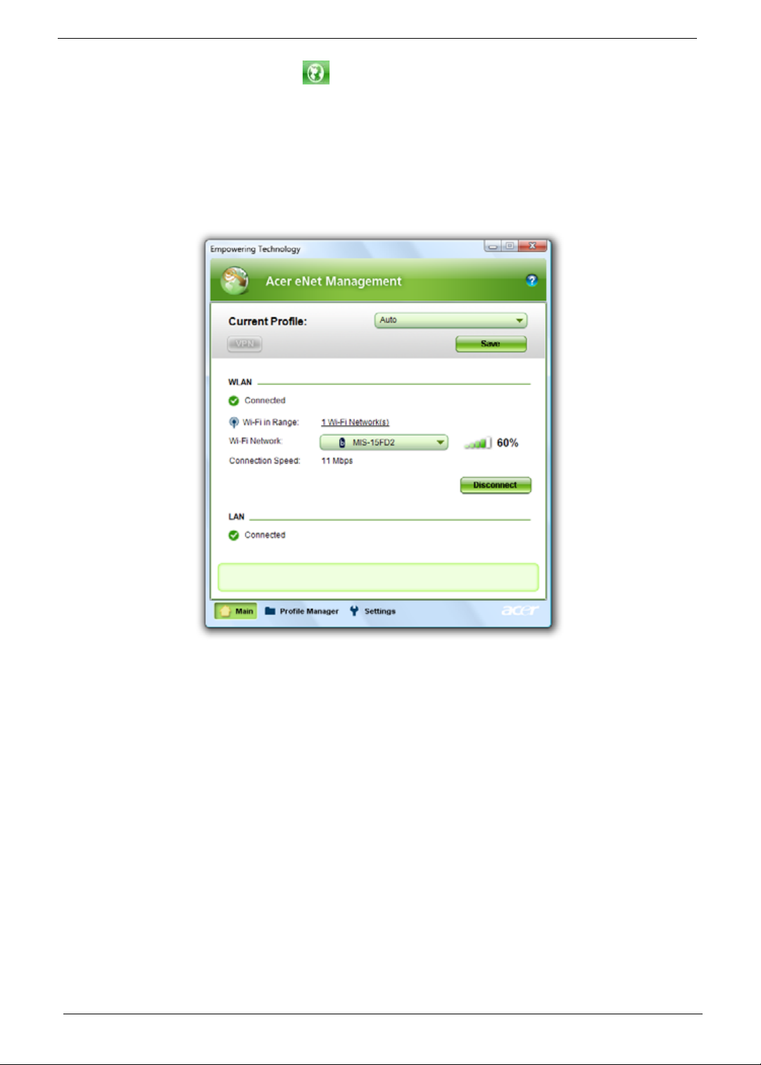
Acer eNet Management
Acer eNet Management helps you quickly connect to both wired and wireless networks in a variety of
locations. To access this utility, select "Acer eNet Management" from the Empowering Technology toolbar or
run the program from the Acer Empowering Technology program group in Start menu. You can also set Acer
eNet Management to start automatically when you boot up your PC.
Acer eNet Management automatically detects the best settings for a new location, while offering you the option
to manually adjust the settings to match your needs.
18 Chapter 1
Page 29
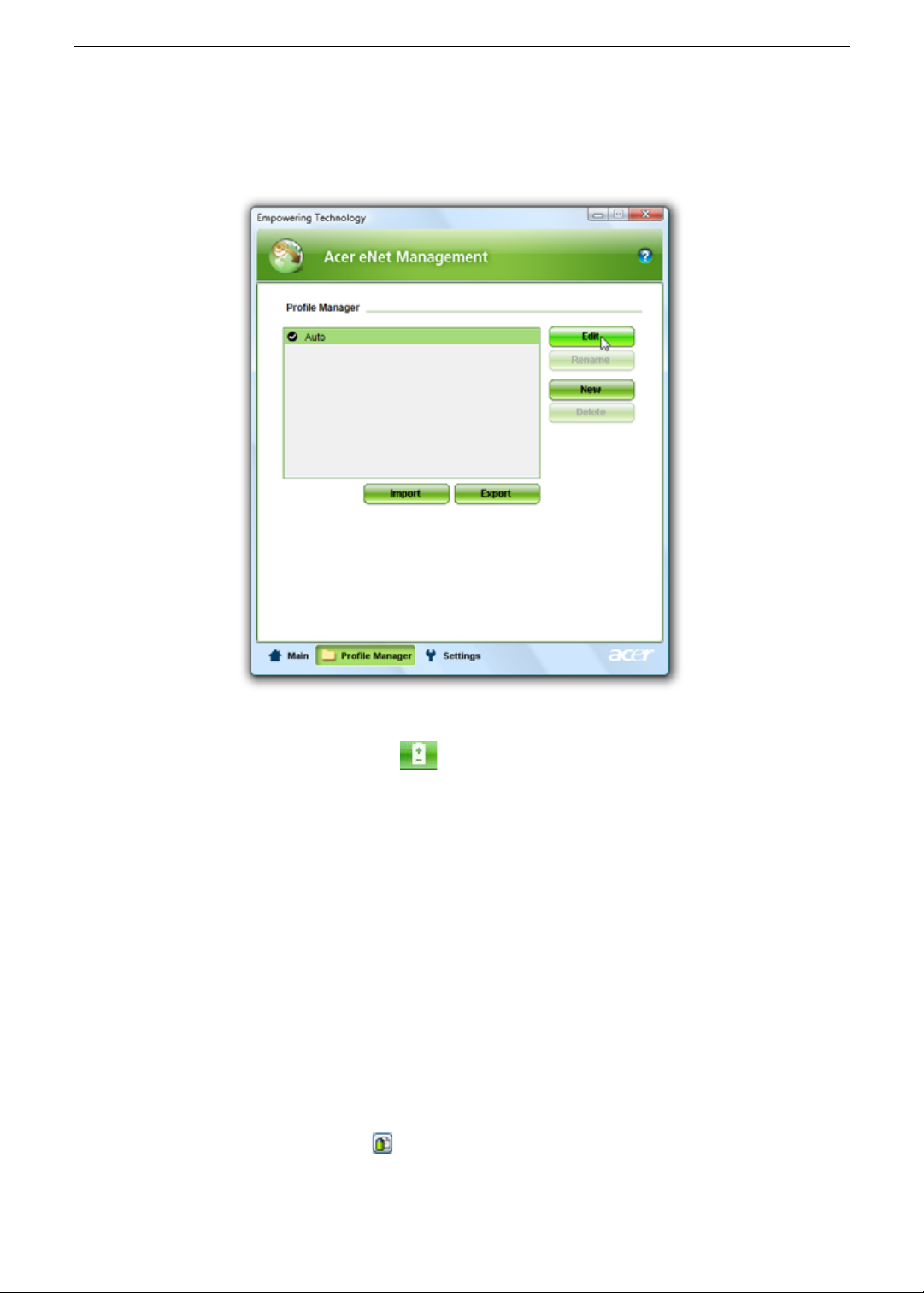
Acer eNet Management can save network settings for a location to a profile, and automatically switch to the
appropriate profile when you move from one location to another. Settings stored include network connection
settings (IP and DNS settings, wireless AP details, etc.), as well as default printer settings. Security and safety
concerns mean that Acer eNet Management does not store username and password information.
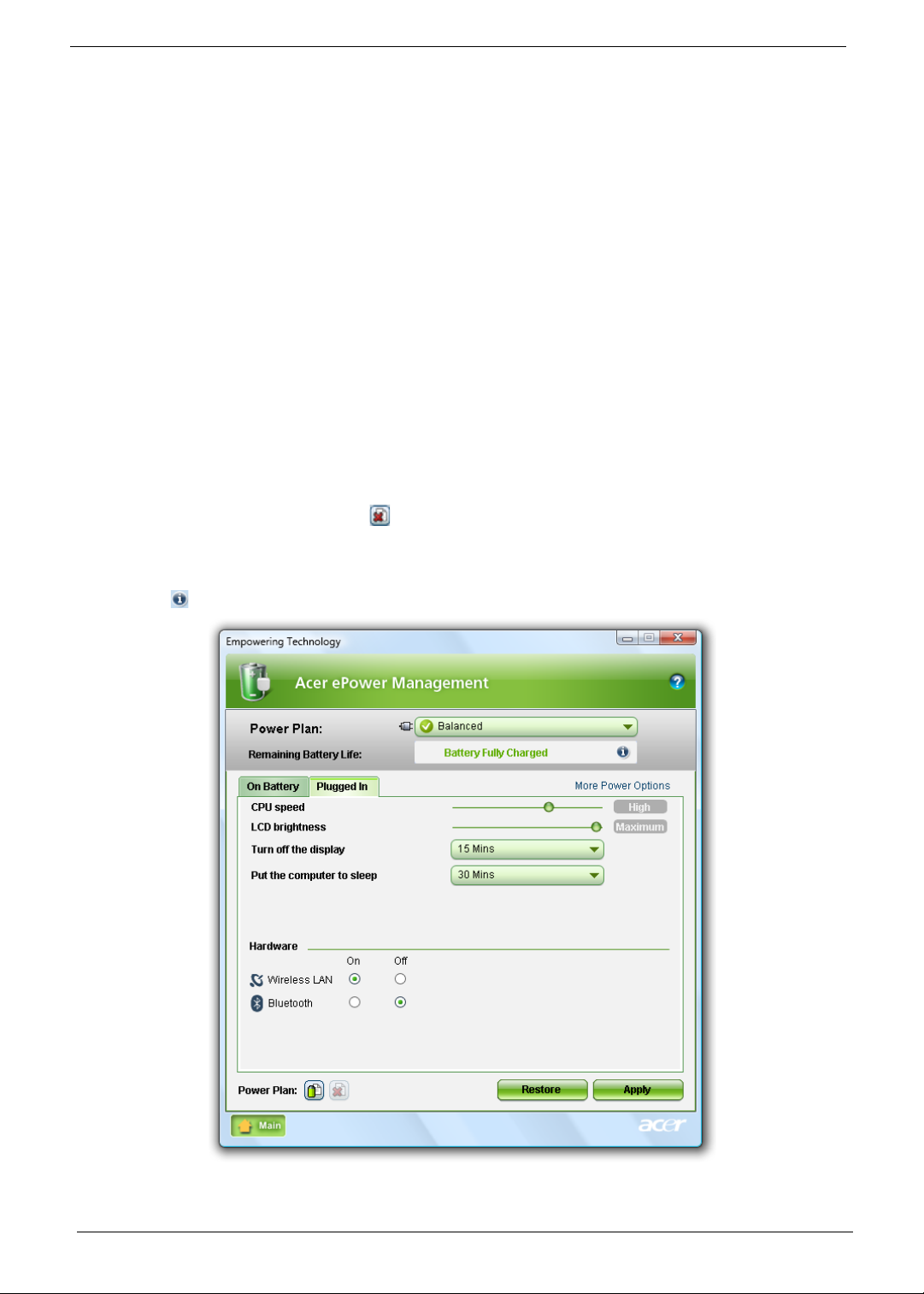
Acer ePower Management
Acer ePower Management features a straightforward user interface for configuring your power management
options. To access this utility, select "Acer ePower Management" from the Empowering Technology toolbar,
run the program from the Acer Empowering Technology program group in Start menu, or right-click the
Windows power icon in the system tray and select "Acer ePower Management".
Using power plans
Acer ePower Management comes with three predefined power plans: Balanced, High performance and Power
saver. You can also create customized power plans. You can create, switch between, edit, delete and restore
power plans, as described below.
View and adjust settings for On Battery and Plugged In modes by clicking the appropriate tabs. You can open
Windows power options by clicking "More Power Options".
NOTE: You cannot delete the predefined power plans.
To create a new power plan:
Creating customized power plans allows you to save and quickly switch to a personalized set of power
options.
1. Click the Create Power Plan icon.
2. Enter a name for your new power plan.
3. Choose a predefined power plan to base your customized plan on.
Chapter 1 19
Page 30
4. If necessary, change the display and sleep settings you want your computer to use.
5. Click "OK" to save your new power plan.
To switch between power plans:
1. Select the power plan you wish to switch to from the drop-down list.
2. Click "Apply".
To edit a power plan:
Editing a power plan allows you to adjust system settings like LCD brightness and CPU speed. You can also
turn on/off system components to extend battery life.
1. Switch to the power plan you wish to edit
2. Adjust settings as required.
3. Click "Apply" to save your new settings.
To delete a power plan:
Y ou cannot delete the power plan you are currently using. If you want to delete the active power plan, switch to
another one first.
1. Select the power plan you wish to delete from the drop-down list.
2. Click the Delete Power Plan icon.
Battery status
For real-time battery life estimates based on current usage, refer to the panel in the upper half of the window.
Click the to view estimated battery life in sleep and hibernate modes.
20 Chapter 1
Page 31

Acer eAudio Management
Acer eAudio Management allows you to easily control the enhanced sound effects of Dolby® Home Theater™
on your system. Select "Movie" or "Game" mode to experience the awesome realism of 5.1-channel surround
sound from just 2 speakers, via Dolby Virtual Speaker technology. "Music" mode lets you enjoy your favorite
tunes, in vivid detail.
Chapter 1 21
Page 32

Acer ePresentation Management
Acer ePresentation Management lets you project your computer's display to an external display device or
projector using the hotkey: <Fn> + <F5>. If auto-detection hardware is implemented in the system and the
external display supports it, your system display will be automatically switched out when an external display is
connected to the system. For projectors and external devices that are not auto-detected, launch Acer
ePresentation Management to choose an appropriate display setting.
NOTE: If the restored resolution is not correct after disconnecting a projector, or you need to use an external
resolution that is not supported by Acer ePresentation Management, adjust your display settings using
Display Properties or the utility provided by the graphics vendor.
22 Chapter 1
Page 33

Acer eDataSecurity Management (for selected models)
Acer eDataSecurity Management is an encryption utility that protects your files from being accessed by
unauthorized persons. It is conveniently integrated with Windows Explorer as a shell extension for quick data
encryption/decryption and also supports on-the-fly file encryption for Lotus Notes and Micro s oft Outlook.
The Acer eDataSecurity Management setup wizard will prompt you for a supervisor password and default
encryption password. This password will be used to encrypt files by default, or you can choose to enter your
own password when encrypting a file.
NOTE: The password used to encrypt a file is the unique key that the system needs to decrypt it. If you lose
the password, the supervisor password is the only other key capable of decrypting the file. If you lose
both passwords, there will be no way to decrypt your encrypted file! Be sure to safeguard all related
passwords!
Chapter 1 23
Page 34

Acer eLock Management
Acer eLock Management is simple yet effective utility that allows you to lock removable storage, optical and
floppy drive devices to ensure that data can't be stolen while your system is unattended.
• Removable Storage Devices — includes USB disk drives, USB pen drives, USB flash drives, USB
MP3 drives, USB memory card readers, IEEE 1394 disk drives, and any other removable storage
devices that can be mounted as a file system when plugged into the system.
• Optical Drive Devices — includes any kind of CD-ROM, DVD-ROM, HD-DVD or Blu-ray drive
devices.
• Floppy Drive Devices — 3.5-inch floppy drives only.
To use Acer eLock Management, the Empowering Technology password must be set first. Once set, you can
apply locks to any of the devices types. Lock(s) will immediately be set without any reboot necessary, and will
remain after rebooting, until removed.
NOTE: If you lose the Empowering T echnology password, there is no method to reset it except by reformatting
your system. Make sure to remember or write down your password.
24 Chapter 1
Page 35

Acer eRecovery Management
Acer eRecovery Management is a versatile backup utility. It allows you to create full or incremental backups,
burn the factory default image to optical disc, and restore from previously created backups or reinstall
applications and drivers. By default, user-created backups are stored to the D:\ drive.
Acer eRecovery Management provides you with:
• Password protection (Empowering Technology password)
• Full and incremental backups to hard disk or optical disc
• Creation of backups:
• Factory default image
• User backup image
• Current system configuration
• Application backup
• Restore and recovery:
• Factory default image
• User backup image
• From previously-created CD/DVD
• Reinstall applications/drivers
NOTE: If your computer did not come with a Recovery CD or System CD, please use Acer eRecovery
Management's "System backup to optical disc" feature to burn a backup image to CD or DVD. To
ensure the best results when recovering your system using a CD or Acer eRecovery Management,
detach all peripherals (except the external Acer ODD, if your computer has one), including your Acer
ezDock.
Chapter 1 25
Page 36

Acer eSettings Management
Acer eSettings Management allows you to inspect hardware specifications, set BIOS passwords and modify
boot options.
Acer eSettings Management also:
• Provides a simple graphical user interface for navigation.
• Prints and saves hardware specifications.
• Lets you set an asset tag for your system.
26 Chapter 1
Page 37

Windows Mobility Center
The Windows Mobility Center collects key mobile-related system settings in one easy-to-find place, so you can
quickly configure your Acer system to fit the situation as you change locations, networks or activities. Settings
include display brightness, power plan, volume, wireless networking on/off, external display settings, display
orientation and synchronization status.
Windows Mobility Center also includes Acer-specific settings like Bluetooth Add Device (if applicable), sharing
folders overview/sharing service on or off, and a shortcut to the Acer user guide, drivers and utilities.
To launch Windows Mobility Center:
• Use the shortcut key < > + <X>
• Start Windows Mobility Center from the Control panel
• Start Windows Mobility Center from the Accessories program group in the Start menu.
Chapter 1 27
Page 38

Using the System Utilities
Note:
Start Control Panel Display
Settings (2)
Extend my windows desktop onto this monitor
Apply OK
Start All Programs Acer GridVista
Acer Bio-Protection (only for certain models) Acer Bio-Protection Fingerprint Solution is a multi-purpose
fingerprint software package integrated with the Microsoft Windows operating system. Utilizing the uniqueness
of one's fingerprint features, Acer Bio-Protection Fingerprint Solution has incorporated protection against
unauthorized access to your computer with centralized password management with Password Bank, easy
music player launching with Acer MusicLaunch, secure Internet favorites via Acer MyLaunch, and fast
application/website launching and login with Acer FingerLaunch, while Acer ProfileLaunch can launch up to
three applications/websites from a single finger swipe.
Acer Bio-Protection Fingerprint Solution also allows you to navigate through web browsers and documents
using Acer FingerNav. With Acer Bio-Protection Fingerprint Solution, you can now enjoy an extra layer of
protection for your personal computer, as well as the convenience of accessing your daily tasks with a simple
swipe of your finger!
For more information refer to the Acer Bio-Protection help files.
Acer GridVista (dual-display compatible)
NOTE: This feature is only available on certain models.
To enable the dual monitor feature of the notebook, first ensure that the second monitor is connected, then
select Start, Control Panel, Display and click on Settings. Select the secondary monitor (2) icon in the
display box and then click the check box Extend my windows desktop onto this monitor. Finally, click
Apply to confirm the new settings and click OK to complete the process.
Acer GridVista is a handy utility that offers four pre-defined display settings so you can view multiple windows
on the same screen. To access this function, please go to Start´ All Programs and click on Acer GridVista.
You may choose any one of the four display settings indicated below:
28 Chapter 1
Page 39

Double (vertical), Triple (primary at left), Triple (primary at right), or Quad Acer Gridvista is dual-display
compatible, allowing two displays to be partitioned independently.
Acer Gridvista is dual-display compatible, allowing two displays to be partitioned independently.
AcerGridVista is simple to set up:
1. Run Acer GridVista and select your preferred screen configuration for each display from the task bar.
2. Drag and drop each window into the appropriate grid.
3. Enjoy the convenience of a well-organized desktop.
NOTE: Please ensure that the resolution setting of the second monitor is set to the manufacturer's
recommended value.
Launch Manager
Launch Manager allows you to set the four easy-launch buttons located above the keyboard. You can access
the Launch Manager by clicking on Start > All Programs > Launch Manager to start the application.
Chapter 1 29
Page 40

Norton Internet Security
Norton Internet Security is an anti-virus utility that can protect against viruses, keeping your data safe and
secure.
How do I check for viruses?
1. Double-click the Norton Internet Security icon on the Windows desktop.
2. Select Tasks & Scans.
3. Select Run Scan to scan your system.
4. When the scan is complete, review the results of the scan.
NOTE: For optimal security, run a Full System Scan when scanning your computer for the first time.
You can schedule customized virus scans that run unattended on specific dates and times or at periodic
intervals. If you are using the computer when the scheduled scan begins, it runs in the background so that you
do not have to stop working.
For more information refer to the Norton Internet Security help files.
30 Chapter 1
Page 41

Hardware Specifications and Configurations
Processor
Item Specification
CPU type Intel® Core™2 Duo mobile processor, supporting Intel® 64
architecture
Core logic Mobile Intel® GM45/PM45 + ICH9M
CPU package Socket M (FCPGA6)
CPU core voltage 1.0375V to 1.3V
CPU Fan True Value Table
CPU Temperature
Core 0 Core 1
58 58 2500 29
66 66 3000 31
74 74 3400 34
85 85 3800 37
100 100 4200 40
• Throttling 50%: On= 100°C; OFF=90°C
• OS shut down at 105°C; H/W shut down at 96°C
BIOS
Item Specification
BIOS vendor Insyde
BIOS Version 1.00 (MP version)
BIOS ROM type Macronix_MX25L8005/ EON_EN25F80
BIOS ROM size 1M bytes
BIOS package SPI Flash part
Supported protocols ACPI 1.0b/2.0/3.0
BIOS password control Set by setup manual
Fan Speed (rpm) SPL Spec (dBA)
PCI 2.2 or later
System/HDD Password Security Control
INT 13h Extensions
PnP BIOS 1.0a
SMBIOS 2.4 or later·
BIOS Boot Specification (Compal, Phoenix, Intel)
Simple Boot Flag 1.0
Boot Block
PCI Bus Power Management Interface Specification
USB Specification 1.1/2.0
USB Boot Up support
Support HD audio
WfM 2.0
Preboot Execution Environment (PXE) 2.1
Boot Integrity Service Application Program Interface (BIS) 1.0·
PC2002/2005 compliant
Intel Enhanced SpeedStep Technology
AHCI support.
Chapter 1 31
Page 42

Cache
Item Specification
Cache controller Built-in CPU
Cache size Up to 6-MB second-level shared cache (See CPU type)
System Memory
Item Specification
Memory controller Built-in
Memory size 0MB (no on-board memory)
DIMM socket number 2 sockets
Supports memory size per socket 2 GB
Supports maximum memory size 4G for 64bit OS (with two 2GB SODIMM)
Supports DIMM type DDR 2 Synchronous DRAM
Supports DIMM Speed 667/800 MHz
Supports DIMM voltage 1.8V and 0.9V
Supports DIMM package 200-pin soDIMM
Memory module combinations You can install memory modules in any combinations as long as
they match the above specifications.
Memory Combinations
Slot 1 Slot 2 Total Memory
0MB 256MB 256MB
0MB 512MB 512MB
0MB 1024MB 1024MB
0MB 2048MB 2048MB
256MB 256MB 512MB
256MB 512MB 768MB
256MB 1024MB 1280MB
256MB 2048MB 2304MB
512MB 256MB 768MB
512MB 512MB 1024MB
512MB 1024MB 1536MB
512MB 2048MB 2560MB
1024MB 0MB 1024MB
1024MB 256MB 1280MB
1024MB 512MB 1536MB
1024MB 1024MB 2048MB
1024MB 2048MB 3072MB
2048MB 0MB 2048MB
2048MB 256MB 2304MB
2048MB 512MB 2560MB
2048MB 1024MB 3072MB
2048MB 2048MB 4096MB
NOTE: Above table lists some system memory configurations. You may combine DIMMs with various
capacities to form other combinations. On above table, the configuration of slot 1 and slot 2 could be
reversed.
32 Chapter 1
Page 43

LAN Interface
Item Specification
LAN Chipset Realtek RTL8111C-GR
Supports LAN protocol 10/100/1000 Mbps
LAN connector type RJ45
LAN connector location Left side
Features PCI-E Giga LAN
Support Wake-On-Lan (AC mode S5)
No ASF 2.0/iAMT 4.0
Bluetooth Interface
Item Specification
Chipset Broadcom 2045 & Broadcom 2070
Data throughput 723 bps (full speed data rate)
Protocol Bluetooth 2.0
Interface Mini USB modul e and built-in antenna
Connector type Mini USB
Wireless Module 802.11b/g
Item Specification
Chipset Intel Shirley Peak and Echo Peak (for Centrino platform)
Atheros WLAN XB63 and Broadcom WLAN BCM4312 (for
Non-Centrino)
Data throughput 11~54 Mbps, up to 270 Mbps for Draft-N
Protocol 802.11b+g, Draft-N
Interface PCI bus (mini PCI socket for wireless module)
Hard Disk Drive Interface
Item
Vendor &
Model
Name
Capacity
(MB)
Bytes per
sector
Data heads 2 3 3/4 4
Drive Format
Disks12 22
Spindle
speed
(RPM)
Performance Specifications
Buffer size 8MB 8MB 8MB 8MB
Interface SATA SATA SATA SATA
HGST 2.5”
HTS542580K9SA0
0 BRONCO-B
SA TA II, WD 2.5”
WD800BEVS22RST0 ML80
SATA
80000 120000 160000 250000
512 512 512 512
5400 RPM 5400 RPM 5400 RPM 5400 RPM
HGST 2.5”
HTS542512K9SA00
BRONCO-B SATA II
WD 2.5”
WD1600BEVS22RST0 ML80
SATA, HGST 2.5”
HTS542516K9SA0
0 BRONCO-B
SATA II
HGST 2.5”
HTS542525K9SA0
0 BRONCO-B
SAT A II, WD 2.5”
WD2500BEVS22UST0 ML80
SATA
Chapter 1 33
Page 44

Item
Max. media
transfer
rate (diskbuffer,
Mbytes/s)
Data
transfer
rate
(host~buffe
r, Mbytes/s)
DC Power Requirements
Voltage
tolerance
Combo Drive Module
Vendor & model name PLDS Corp./DS-8A2S, Pioneer/DVR-TD08RS, Hitachi/GSA-T50N,
Performance Specification With CD Diskette With DVD Diskette
Transfer rate (KB/sec) Sustained:
Buffer Memory 2MB
Interface SATA
Applicable disc format App licable media types:
Loading mechanism Drawer (Solenoid Open)
Power Requirement
Input Voltage DC 5 V +/- 0.25V
540 540 540 540
100 MB/Sec.
Ultra DMA mode-5
5V(DC) +/- 5% 5V(DC) +/- 5% 5V(DC) +/- 5% 5V(DC) +/- 5%
Item Specification
Acer/UJ870ABAA-A, Sony/BC-5500S-AR, Toshiba/TS-L633A
Max 3.6Mbytes/sec
CD-ROM, CD-R and CD-RW
DVD-ROM (4.7G/8.54G) single layer
on single/double side (Read Only),
DVD-ROM dual layer (PTP/OTP) on
single/double side, (Read Only)
DVD-R (3.9G, 4.7G for General and Authoring),
DVD-RW, DVD+RW (4.7G),
DVD+R, DVD+R DL, DVD-R DL
DVD-RAM
CD-DA, CD-TEXT, CD ROM Mode-1,
CD-ROM/XA Mode-2 Form-1 and Form-2,
CD-I Ready, Video-CD (MPEG-1),
Photo-CD, Enhance CD,
CD extra, I-Trax CD and UDF
DVD-ROM, DVD-Video, DVD-Audio,
DVD-R single/multi border(s)
DVD+R single/multi session(s)
DVD-RW
DVD+RW
DVD-RAM
Tact SW (Open)
Emergency Release (draw open hole)
150 MB/Sec.
Ultra DMA mode-5
150 MB/Sec.
Ultra DMA mode-5
Sustained:
Max 10.8Mbytes/sec
150 MB/Sec.
Ultra DMA mode-5
34 Chapter 1
Page 45

Audio Interface
Item Specification
Audio Controller Realtek ALC888S-VC
Audio onboard or optional Built-in
Mono or Stereo Stereo
Resolution True 5.1
Compatibility Headphone-out/Line-out/SPDIF-out: UAA
Supports Dolby Home Theater
Sampling rate 1Hz resolution VSR (Variable Sampling Rate)
Internal microphone Mic Array (ForteMe dia, Digital Mic type)
Internal speaker / Quantity 2.0 Watt speaker/10cc chamber/speaker size 18 phi, x2
Video Memo ry
Item Specification
Chipset UMA NB9PGE2-256MB-GDDR3/NB9MGS-256MB-
GDDR2
Memory size 256 MB
USB Interface
Item Specification
Chipset ICH9M
USB Compliancy Level 2.0
OHCI USB 1.1 and USB 2.0 Host controller
Number of USB port 3
Location Two on the left side/one on the right side
Serial port function control Enable/Disable by BIOS Setup
System Board Major Chips
Item Controller
Core logic Intel® Cantiga (GM-45 & PM-45)/ICH9M Express Chipset
VGA UMA
LAN Realtek RTL8111C-GR
USB 2.0 In tel ICH9M
Super I/O controller N/A
MODEM Foxconn/LSI AM5 V2 1.5_3.3V
Bluetooth Broadcom 2045 & Broadcom 2070
Wireless 802.11 b+g Atheros WLAN XB63 and Broadcom WLAN BCM4312
Audio Codec Realtek ALC888S-VC
Keyboard
Item Specification
Keyboard controller LPC interface
Total number of keypads 88-/89-/93-key
Windows logo key Yes
Internal & external keyboard work
simultaneously
Chapter 1 35
Plug USB keyboard to the USB port directly: Yes
Page 46

Battery
Item Specification
Vendor & model name Sanyo AS07A
Sony AS07A
Simplo AS07A
Panasonic AS07A
Battery Type Li-ion
Pack capacity 4400 mAh
Number of battery cell 6
Package configuration 3 cells in series, 2 series in
parallel
Normal voltage 11.1V (Panasonic 10.8V)
Charge voltage 12.6V
LCD 14.1”
Item Specification
Vendor/model name LG.Philips/LP141WX3, AUO/B141EW04 V4,
Chimei/N141I3 - L02, Samsung/LTN141W3-L01
Screen Diagonal (mm) 14.1 inches
Active Area (mm) 303.74 x 189.84 mm
Display resolution (pixels) 1280 x 800 WXGA
Pixel Pitch 0.2373 × 0.2373 mm
Pixel Arrangement R.G.B. Vertical Stripe
Display Mode Transmissive mode, normally white
2
200 cd/m2(Typ.5 point)
Typical White Luminance (cd/m
)
also called Brightness
Luminance Uniformity 1.3 max.
Contrast Ratio 300 minimum
Response Time (Optical Rise
16
Time/Fall Time) msec
Nominal Input Voltage VDD +3.3V
Typical Power Consumption (watt) 1.4W max.
Weight (without inverter) 400g max.
Physical Size (mm) 319.5 (±0.5) x 205.5 (± 0.5) x 5.5 max.
Electrical Interface 3.3V LVDS interface with 1 pixel/clock
Support Color g reater than 262144
Viewing Angle (degree)
Horizontal: Right/Left
Vertical: Upper/Lower
Minimum: 40/40, Typical: 45/45
Minimum: 10/30, Typical: 20/35
Temperature Range (°C)
Operating
Storage (shipping)
0 to +50
-20 to +60
36 Chapter 1
Page 47

LCD Inverter
Item Specification
Vendor & model name YEC YNV-C01H
Brightness conditions N/A
Input voltage (V) 9~20(V)
Input current (mA) Typical 0.33(mA)
Output voltage (V, rms) Typical 650 Vrms
Output current (mA, rms) MAX. 6.8mA
Output voltage frequency (k Hz) 45~65 (KHz)
AC Adapter
Item Specification
Input rating 100~240Vac/ 50-60Hz
Maximum input AC current 1.5A
Inrush current No damage
Efficiency Meet EPA level-4 requirement
System Power Management
ACPI mode Power Management
Mech. Off (G3) All devices in the system are turned off completely.
Soft Off (G2/S5) OS initiated shutdown. All devices in the system are turned
off completely.
Working (G0/S0) Individual devices such as the CPU and hard disk may be
power managed in this state.
Suspend to RAM (S3) CPU set power down
VGA Suspend
PCMCIA Suspend
Audio Power Down
Hard Disk Power Down
CD-ROM Power Down
Super I/O Low Power mode
Save to Disk (S4) Also called Hibernation Mode. System saves all system
states and data onto the disc prior to power off the whole
system.
Chapter 1 37
Page 48

38 Chapter 1
Page 49

Chapter 2
System Utilities
BIOS Setup Utility
The BIOS Setup Utility is a hardware configuration program built into your computer’s BIOS (Basic Input/
Output System).
Y our computer is already properly configured and optimized, and you do not need to run this utility . However, if
you encounter configuration problems, you may need to run Setup. Please also refer to Chapter 4
Troubleshooting when problem arises.
To activate the BIOS Utility, press F2 during POST (when “Press <F2> to enter Setup” message is prompted
on the bottom of screen).
Press F2 to enter setup. The default parameter of F12 Boot Menu is set to “disabled”. If you want to change
boot device without entering BIOS Setup Utility, please set the parameter to “enabled”.
Press <F12> during POST to enter multi-boot menu. In this menu, user can change boot device without
entering BIOS SETUP Utility.
Navigating the BIOS Utility
There are six menu options: Information, Main, Advanced, Security, Boot, and Exit.
Follow these instructions:
• To choose a menu, use the left and right arrow keys.
• To choose an item, use the up and down arrow keys.
• To change the value of a parameter, press F5 or F6.
• A plus sign (+) indicates the item has sub-items. Press Enter to expand this item.
• Press Esc while you are in any of the menu options to go to the Exit menu.
• In any menu, you can load default settings by pressing F9. You can also press F10 to save any
changes made and exit the BIOS Setup Utility.
NOTE: You can change the value of a parameter if it is enclosed in square brackets. Navigation keys for a
particular menu are shown on the bottom of the screen. Help for parameters are found in the Item
Specific Help part of the screen. Read this carefully when making changes to parameter values. Please
note that system information is subject to different models.
Chapter 2 39
Page 50

Information
InsydeH20 Setup Utility Rev. 3.5
Advanced Security Power Boot Exit
CPU Type: Intel (R) Core (TM)2 Duo CPU @ 2.40GHz
CPU Speed: 2.40GHz
HDD Model Name: Hitachi HTS543516K9SA00
HDD Serial Number: 071129BB0C02WGHDKKGC
ATAPI Model Name: Slimtype DVD A DS8A2S
System BIOS Version: V0.15T2
VGA BIOS Version: Intel V1588
Serial Number:
Asset Tag Number:
Product Name: Aspire 4930
Manufacturer Name: Acer
UUID: 864BD4BE-6B22-5843-38D2-001B38D637FC
r
The Information screen displays a summary of your computer hardware information.
Information Main
F1 Help ↑↓ Select Item F5/F6 Change Item F9 Setup Default
ESC Exit ←→ Select Menu Ente
SelectXSubmenu F10 Save and Exit
NOTE: The system information is subject to different models.
Parameter Description
CPU Type This field shows the CPU type and speed of the system.
CPU Speed This field shows the speed of the CPU.
HDD Model Name This field shows the model name of HDD installed on primary IDE master.
HDD Serial Number This field displays the serial number of HDD installed on primary IDE master.
ATAPI Model Name This field shows the model name of the Optical device installed in the system.
System BIOS Version Displays system BIOS version.
VGA BIOS Version This field displays the VGA firmware version of the system.
Serial Number This field displays the serial number of this unit.
Asset Tag Number This field displays the asset tag number of the system.
Product Name This field shows product name of the system.
Manufacturer Name This field displays the manufacturer of this system.
UUID Number Universally Unique Identifier (UUID) is an identifier standard used in software
construction, standardized by the Open Software Foundation (OSF) as part of
the Distributed Computing Environment (DCE).
40 Chapter 2
Page 51

Main
InsydeH20 Setup Utility Rev. 3.5
Advanced Security Power Boot Exit
Item Specific Help
System Time
This is the help for the
System Date [04/21/2008] hour field. Valid range
is from 0 to 23.
Total Memory 3017 MB INCREASE/REDUCE : F5/F6
Video Memory [32MB]
Quick Boot [Enabled]
Network Boot [Enabled]
F12 Boot Menu [Disabled]
D2D Recovery [Enabled]
SATA Mode [ACHI]
r
The Main screen allows the user to set the system time and date as well as enable and disable boot option
and recovery.
Information Main
[13:04:04]
F1 Help ↑↓ Select Item F5/F6 Change Item F9 Setup Default
ESC Exit
NOTE: The screen above is for your reference only. Actual values may differ.
The table below describes the parameters in this screen. Settings in boldface are the default and suggested
parameter settings.
Parameter Description Format/Option
System Time Sets the system time. The hours are displayed with 24-
System Date Sets the system date. Format MM/DD/YYYY
System Memory This field reports the memory size of the system.
Video Memory
Quick Boot Allows startup to skip certain tests while booting,
Network Boot Enables, disables the system boot fro m LAN (remote
F12 Boot Menu Enables, disables Boot Menu during POST. Option: Disabled or
D2D Recovery Enables, disables D2D Recovery function. The function
SATA Mode Control the mode in which the SATA controller should
←→ Select Menu Ente
hour format.
Memory size is fixed to 3071 MB.
Shows the video memory size. VGA Memory size=32 MB
decreasing the time needed to boot the system.
server).
allows the user to create a hidden partition on hard disc
drive to store operation system and restore the system
to factory defaults.
operate.
SelectXSubmenu F10 Save and Exit
Format: HH:MM:SS
(hour:minute:second)
(month/day/year)
N/A
N/A
Option: Enabled or
Disabled
Option: Enabled or
Disabled
Enabled
Option: Enabled or
Disabled
Option: AHCI Mode or IDE
Mode
NOTE: The sub-items under each device will not be shown if the device control is set to disable or auto. This is
because the user is not allowed to control the settings in these cases.
Chapter 2 41
Page 52

Advanced
InsydeH20 Setup Utility Rev. 3.5
Advanced Security Power Boot Exit
Item Specific Help
Configures Boot
Settings.
Express Card [Disabled]
↑↓
r
The Advanced screen allows the user to configure the various advanced BIOS options.
IMPORTANT:Making incorrect settings to items on these pages may cause the system to malfunction. Unless
you have experience adjusting these items, we recommend that you leave these settings at the
default values. If making settings to items on these pages causes your system to malfunction or
prevents the system from booting, open BIOS and choose Load Optimal Defaults in the Exit menu to
boot up normally.
Information Main
X
Boot Configuration
X
Peripheral Configuration
X
IDE Configuration
X
Video Configuration
X
USB Configuration
X
Chipset Configuration
X
ACPI Table/Features Control
X
PCI Express Root Port 1
X
PCI Express Root Port 2
X
PCI Express Root Port 3
X
PCI Express Root Port 4
X
PCI Express Root Port 5
X
PCI Express Root Port 6
X
ASF Configuration
F1 Help
ESC Exit
The table below describes the items, menus, and submenus in this screen. Settings in boldface are the default
and suggested parameter settings.
Parameter Description Submenu Items
Boot
Configuration
Peripheral
Configuration
IDE
Configuration
Video
Configuration
Select Item F5/F6 Change Item F9 Setup Default
←→ Select Menu Ente
Enter the Boot Configuration menu. • Numlock
Enter the Peripheral Configuration menu. • Serial Port A
Enter the IDE Configuration menu. • IDE Controller
Enter the Video Configuration menu. • IGD Device2, Function1
SelectXSubmenu F10 Save and Exit
• Zip Emulation Type
• Infrared Port
• Azalia
•LAN
• HDC C onfigure as
• ACHI Option ROM Support
• SATA Port 0, 1, 4, and 5 Hotplug
• Channel 1 to 4 Master and Slave
• IGD Pre-allocate Memory
• IGD DVMT Size
• Clock Chi p Inti a l ize
• Enabled CK SSC
• IGD Boot Type
• IGD LCD Panel T ype
• IGD TV
42 Chapter 2
Page 53

Parameter Description Submenu Items
USB
Configuration
Chipset
Configuration
ACPI Table/
Features Control
Express Card Disable or Enable the Express Card
PCI Express
Root Port 1 to 6
ASF
Configuration
Enter the USB Configuration menu. • USB Driver Select
• EHCI 1 and 2
• UHCI 1 to 5
• Per-Port Control
Enter the Chipset Configuration menu. • Port 80h Cycles
• DMI Link ASPM Control
• PCI Latency Timer
•VT-d
Enter the ACPI Table/Features Control
menu.
solution for windows Standby and
Hibernation.
Enter the PCI Port 1 to 6 configuration
menus.
Enter the ASF Configuration menu. • Mini Watchdog Timeout
• FACP C2 Latency Value
• FACP C3 Latency Value
• FACP RTC S4 Wakeup
• APIC IO APIC Mode
• HPET Support
• Base Address Select
N/A
• VC1 Enable
• ASPM
•URR
•FER
•NFER
•CER
•CTO
• SEFE
• SENFE
• SECE
• PME Interrupt
•PME SCI
• Hot Plug SCI
• BIOS Boot Timeout
• OS Boot Timeout
• Power-on wait time
Chapter 2 43
Page 54

Security
InsydeH20 Setup Utility Rev. 3.5
Advanced Security Power Boot Exit
Item Specific Help
Supervisor Password Is: Clear Install or Change the
User Password Is: Clear password and the length
HDD Password Is: Clear of password must be less
than eight words.
Set Supervisor Password [32MB]
Set User Password
Set Hdd Password
Power on password [Enabled]
r
The Security screen contains parameters that help safeguard and protect your computer from unauthorized
use.
Information Main
F1 Help ↑↓ Select Item F5/F6 Change Item F9 Setup Default
ESC Exit
The table below describes the parameters in this screen. Settings in boldface are the default and suggested
parameter settings.
Parameter Description Option
Supervisor Password Is Shows the setting of the Supervisor password Clear or Set
User Password Is Shows the setting of the user password. Clear or Set
HDD Password Is Shows the setting of the hard disk password. Clear or Set
Set Supervisor Password Press Enter to set the supervisor password. When
Set User Password Press Enter to set the user password. When user
Set HDD Password Enter HDD Password.
Password on Boot Defines whether a password is required or not while
←→ Select Menu Ente
set, this password protects the BIOS Setup Utility
from unauthorized access. The user can not either
enter the Setup menu nor change the value of
parameters.
password is set, this password protects the BIOS
Setup Utility from unauthorized access. The user can
enter Setup menu only and does not have right to
change the value of parameters.
the events defined in this group happened. The
following sub-options are all requires the Supervisor
password for changes and should be grayed out if the
user password was used to enter set u p.
SelectXSubmenu F10 Save and Exit
Disabled or
Enabled
NOTE: When you are prompted to enter a password, you have three tries before the system halts. Don’t forget
your password. If you forget your password, you may have to return your notebook computer to your
dealer to reset it.
44 Chapter 2
Page 55

Setting a Password
Follow these steps as you set the user or the supervisor password:
1. Use the ↑ and ↓ keys to highlight the Set Supervisor Password parameter and press the Enter key. The
Set Supervisor Password box appears:
2. Type a password in the “Enter New Password” field. The password length can not exceeds 8
alphanumeric characters (A-Z, a-z, 0-9, not case sensitive). Retype the password in the “Confirm New
Password” field.
IMPORTANT:Be very careful when typing your password because the characters do not appear on the screen.
3. Press Enter. After setting the password, the computer sets the User Password parameter to “Set”.
4. If desired, you can opt to enable the Password on boot parameter.
5. When you are done, press F10 to save the changes and exit the BIOS Setup Utility.
Removing a Password
Follow these steps:
1. Use the w and y keys to highlight the Set Supervisor Password parameter and press the Enter key. The
Set Password box appears:
2. Type the current password in the Enter Current Password field and press Enter.
3. Press e twice without typing anything in the Enter New Password and Confirm New Password fields. The
computer then sets the Supervisor Password parameter to “Clear”.
4. When you have changed the settings, press u to save the changes and exit the BIOS Setup Utility.
Chapter 2 45
Page 56

Changing a Password
1. Use the ↑ and ↓ keys to highlight the Set Supervisor Password parameter and press the Enter key. The
Set Password box appears.
2. Type the current password in the Enter Current Password field and press Enter.
3. Type a password in the Enter New Password field. Retype the password in the Confirm New Password
field.
4. Press Enter. After setting the password, the computer sets the User Password parameter to “Set”.
5. If desired, you can enable the Password on boot parameter.
6. When you are done, press F10 to save the changes and exit the BIOS Setup Utility.
If the verification is OK, the screen will display as following.
The password setting is complete after the user presses Enter.
If the current password entered does not match the actual current password, the screen will show you the
Setup Warning.
If the new password and confirm new password strings do not match, the screen will display the following
message.
46 Chapter 2
Page 57

Power
InsydeH20 Setup Utility Rev. 3.5
Advanced Security Power Boot Exit
Item Specific Help
These items control
various CPU parameters.
ACPI S3: [Enabled]
Wake on PME [Enabled]
Wake on Modem Ring [Enabled]
Auto wake on S5 [Disabled]
Quickly S4 Resume [Disabled]
r
The Power screen allows the user to configure various CPU and power management options and device
wakeup behavior.
Information Main
X
Advanced CPU Control
X
Platform Power Management
F1 Help ↑↓ Select Item F5/F6 Change Item F9 Setup Default
ESC Exit
The table below describes the items, menus, and submenus in this screen. Settings in boldface are the default
and suggested parameter settings.
Parameter Description Submenu Items
Advanced CPU
Control
←→ Select Menu Ente
Enter the Advanced CPU Control menu. • P-States (IST)
SelectXSubmenu F10 Save and Exit
• Boot performance mode
• Thermal Mode
• CMP Support
• Use XD capability
• VT Support
•C-States
• Enhanced C-States
• C-State Pop Up Mode
• C-State Pop Down Mode
• C4 Exit Timing Mode
• DeepC4
•Hard C4E
• Enable C6
•EMTTM
• Bi-directional PROCHOT#
• Dynamic FSB Switching
• Turbo Mode
• ACPI 3.0 T-States
•DTS
• DTS Calibration
• Thermal Trip Points Setting (Fan
On Temp., Throttle On Temp.)
Chapter 2 47
Page 58

Parameter Description Submenu Items
Platform Power
management
ACPI S3 Enable or Disable ACPI S1/S3 Sleep State N/A
Wake on PME Enable or Disable wake up when the
Wake on Modem
Ring
Auto wake on S5 Disable or Enable auto wake up by date
Quickly S4
Resume
Enter the Platform Power Management
menu.
system power is off and a PCI Power
Management Enable wake up event occurs.
Enable or Disable wake up when the
system power is off and a modem attached
to the serial port is ringing.
and time or at a fixed time everyday.
Disable or Enable optional quick boot from
S4 Resume.
• PCI Clock Run
• _CST - C4 Latency Value
• C4 on C3 - Deeper Sleep
N/A
N/A
N/A
N/A
48 Chapter 2
Page 59

Boot
InsydeH20 Setup Utility Rev. 3.5
Advanced Security Power Boot Exit
Item Specific Help
Boot priority order:
a device, then press
1. IDE0 : Hitachi HTS542516K9SA00 <F5> to move it down the
2. IDE1 : Slimtype DVD A DS8A2S list, or <F6> to move
3 . USB FDD : it up the list. Press
4. Network Boot : Realtek Boot Agent <Esc> to escape the menu
5. USB HDD :
6. USB CDROM :
r
This menu allows the user to decide the order of boot devices to load the operating system. Bootable devices
includes the USB diskette drives, the onboard hard disk drive and the DVD drive in the module bay.
Information Main
Use <↑> or <↓> to select
F1 Help ↑↓ Select Item F5/F6 Change Item F9 Setup Default
ESC Exit
←→ Select Menu Ente
SelectXSubmenu F10 Save and Exit
Chapter 2 49
Page 60

Exit
InsydeH20 Setup Utility Rev. 3.5
Advanced Security Power Boot Exit
Item Specific Help
Exit Saving Changes Exit System Setup and
Exit Discarding Changes save your changes to
Load Setup Defaults CMOS.
Discard Changes
Save Changes
r
The Exit screen allows you to save or discard any changes you made and quit the BIOS Utility.
Information Main
F1 Help ↑↓ Select Item F5/F6 Change Item F9 Setup Default
ESC Exit
←→ Select Menu Ente
SelectXSubmenu F10 Save and Exit
The table below describes the parameters in this screen.
Parameter Description
Exit Saving Changes Exit System Setup and save your changes to CMOS.
Exit Discarding
Changes
Load Setup Default Load default values for all SETUP item.
Discard Changes Load previous values from CMOS for all SETUP items.
Save Changes Save Setup Data to CMOS.
Exit utility without saving setup data to CMOS.
50 Chapter 2
Page 61

BIOS Flash Utility
The BIOS flash memory update is required for the following conditions:
• New versions of system programs
• New features or options
• Restore a BIOS when it becomes corrupted.
Use the Phlash utility to update the system BIOS flash ROM.
NOTE: If you do not have a crisis recovery diskette at hand, then you should create a Crisis Recovery
Diskette before you use the Phlash utility.
NOTE: Do not install memory-related drivers (XMS, EMS, DPMI) when you use the Phlash.
NOTE: Please use the AC adaptor power supply when you run the Phlash utility. If the battery pack does not
contain enough power to finish BIOS flash, you may not boot the system because the BIOS is not
completely loaded.
Fellow the steps below to run the Phlash.
1. Prepare a bootable diskette.
2. Copy the flash utilities to the bootable diskette.
3. Then boot the system from the bootable diskette. The flash utility has auto-execution function.
Chapter 2 51
Page 62

Remove HDD/BIOS Utility
This section provide you with removing HDD/BIOS method:
Remove HDD Password:
• If you key in wrong HDD password for three time, “HDD password error code” would display on the
screen. See the image below.
• If you need to solve HDD password locked problem, you can run HDD_PW.EXE
1.
Key in “hdd_pw 15494 0”
2. Select “2”
3. Choose one upper-case string
• Reboot system and key in “0KJFN42” or “UVEIQ96” to HDD user password.
52 Chapter 2
Page 63

Chapter 2 53
Page 64

Remove BIOS Password:
• If you key in wrong Supervisor Password for three time, “System Disabled” would display on the
screen. See the image below.
• If you need to solve BIOS password locked problem, you can run BIOS_PW.EXE
1.
Key in “bios_pw 14452 0”
2. Choose one upper-case string
• Reboot the system and key in “qjjg9vy” or “07yqmjd” to BIOS user password.
54 Chapter 2
Page 65

Chapter 2 55
Page 66

56 Chapter 2
Page 67

Machine Disassembly and Replacement
This chapter contains step-by-step procedures on how to disassemble the notebook computer for
maintenance and troubleshooting.
Disassembly Requirements
To disassemble the computer, you need the following tools:
• Wrist grounding strap and conductive mat for preventing electrostatic discharge
• Flat screwdriver
• Philips screwdriver
• Hex screwdriver
• Plastic flat screwdriver
• Plastic tweezers
NOTE: The screws for the different components vary in size. During the disassembly process, group the
screws with the corresponding components to avoid mismatch when putting back the components.
Chapter 3
Chapter 3 57
Page 68

General Information
Pre-disassembly Instructions
Before proceeding with the disassembly procedure, make sure that you do the following:
1. Turn off the power to the system and all peripherals.
2. Unplug the AC adapter and all power and signal cables from the system.
3. Place the system on a flat, stable surface.
4. Remove the battery pack.
Disassembly Process
The disassembly process is divided into the following stages:
• External module disassembly
• Main unit disassembly
• LCD module disassembly
The flowcharts provided in the succeeding disassembly sections illustrate the entire disassembly sequence.
Observe the order of the sequence to avoid damage to any of the hardware components. For example, if you
want to remove the main board, you must first remove the keyboard, then disassemble the inside assembly
frame in that order.
Main Screw List
Screw Quantity Part Number
M2.5*8 (NL) 15 MA000005YG0
M2.5*5 (NL) 22 MA000007YG0
M2.5*3 (NL) 2 MA000005WG0
M2*3 (NL) 36 MA0000060G0
M2.5*4 (NL) 2 MA0000005G0
M2*6 (NL) 4 MMCK20060G0
M2*4-NI (NL) 5 MACK20040G0
M3*3 (NL) 4 MAAA03032G0
M2*6.5 4 MA0000096G0
M2.5*5.0 2 MA000002NG0
M2.5*6.5 4 MA000006C00
58 Chapter 3
Page 69

External Module Disassembly Process
External Modules Disassembly Flowchart
The flowchart below gives you a graphic representation on the entire disassembly sequence and instructs you
on the components that need to be removed during servicing. For example, if you want to remove the main
board, you must first remove the keyboard, then disassemble the inside assembly frame in that order.
Screw List
Item Screw Color Part No.
Chapter 3 59
Page 70

Removing the Battery Pack
1. Turn computer over.
2. Slide the battery lock/unlock latch to the unlock position.
3. Slide and hold the battery release latch to the release position (1), then slide out the battery pack from the
main unit (2).
60 Chapter 3
Page 71

Removing the SD dummy card
1. Push the SD dummy card all the way in to eject it (1, 2).
2. Pull it out from the slot.
Chapter 3 61
Page 72

Removing the ExpressCard dummy card
1. Push the ExpressCard dummy card all the way in to eject it.
2. Pull it out from the slot.
62 Chapter 3
Page 73

Removing the Lower Covers
1. See “Removing the Battery Pack” on page 60.
2. See “Removing the SD dummy card” on page 61.
3. See “Removing the ExpressCard dummy card” on page 62.
4. Remove the five screws from the memory, HDD, and WLAN bays.
Step Size (Quantity) Color Torque
Memory Cover M2.5*8 NL (2) Black
HDD Cover M2*6 NL (2) Black
WLAN Cover M2.5*8 NL (1) Black
5. Carefully open the memory cover.
Chapter 3 63
Page 74

6. Remove the HDD cover as shown.
7. Remove the WLAN cover as shown.
64 Chapter 3
Page 75

Removing the DIMM Module
1. See “Removing the Battery Pack” on page 60.
2. Remove the Memory Module cover See “Removing the Lower Covers” on page 63.
3. Push out the release latches on both sides of the DIMM socket to release the DIMM module.
4. Remove the DIMM module.
5. Repeat steps for the second DIMM module if present.
Chapter 3 65
Page 76

Removing the WLAN Board Module
1. See “Removing the Battery Pack” on page 60.
2. Remove the WLAN cover. See “Removing the Lower Covers” on page 63.
3. Disconnect the antenna cables from the WLAN board.
4. Move the antenna away and remove the two screws (A) on the WLAN board to release the WLAN board.
Step Size (Quantity) Color Torque
1~2 M 2 x L3 (2) Black 1.6 kgf-cm
66 Chapter 3
Page 77

5. Detach the WLAN board from the WLAN socket.
NOTE: When attaching the antenna back to the WLAN board, make sure the cables are arranged properly.
Chapter 3 67
Page 78

Removing the Hard Disk Drive Module
1. See “Removing the Battery Pack” on page 60.
2. Remove the HDD cover, See “Removing the Lower Covers” on page 63.
3. Use the mylar tab to slide and lift up the hard disk drive module to remove.
NOTE: To prevent damage to device, avoid pressing down on it or placing heavy objects on top of it.
4. Remove the four screws securing the hard disk to the carrier.
68 Chapter 3
Page 79

5. Remove the HDD from the carrier.
Chapter 3 69
Page 80

Removing the Optical Drive Module
1. See “Removing the Battery Pack” on page 60.
2. Remove the Memory cover. See “Removing the Lower Covers” on page 63.
3. Remove the screw securing the ODD module.
4. Carefully use a plastic screw driver to release the locking catch.
70 Chapter 3
Page 81

5. Pull the optical drive module out from the main unit.
6. Remove the two screws (A) securing the ODD bracket and remove the ODD bracket from the optical disk
drive module.
Chapter 3 71
Page 82

7. Insert a pin in the eject hole of the ODD to eject the ODD tray.
8. Press down on the locking catch to release the ODD cover, and remove.
Step Size (Quantity) Color Torque
1 M2.5 x L5 (1) Black
5 M2 x L4 (3) Black 1.6 Kgf-cm
72 Chapter 3
Page 83

Main Unit Disassembly Process
Main Unit Disassembly Flowchart
Screw List
Item Screw Color Part No.
A M2 x L3 Black 86.00D29.620
D M2 x L5 Black 86.00E32.725
F M2 x L4 Black 86.00F24.724
H M2.5 x L8 Black 86.00E34.738
Chapter 3 73
Page 84

Removing the Switch Cover
CAUTION: Using tools to remove the Switch Cover may cause damage to the outer casing. It is
recommended that only fingers are used to remove the Switch Cover.
1. See “Removing the Battery Pack” on page 60.
2. Locate and remove the two securing screws as shown.
Step Size (Quantity) Color Torque
2 M2.5 x 5 (2) Black
3. Turn the computer over and open the LCD module fully to expose the Switch Cover.
4. Lift the Switch Cover as shown, leftside first.
74 Chapter 3
Page 85

5. Turn the Switch Cover over to expose the interface cable and detach it using the tweezers.
6. Lift the Switch Cover clear of the chassis.
Chapter 3 75
Page 86

Removing the Keyboard
1. See “Removing the Battery Pack” on page 60..
2. Push down on the two latches securing the keyboard to the upper case.
3. Lift the keyboard away from the chassis as shown .
76 Chapter 3
Page 87

4. Turn over the keyboard on the Touch Pad area.
5. Disconnect both sides of the keyboard cable from the mainboard to remove the keyboard.
Chapter 3 77
Page 88

Removing the Antenna
1. Remove the Antenna Cables from the securing pins as shown.
78 Chapter 3
Page 89

2. Turn the computer over. Remove the adhesive tape from the antenna cable.
3. Feed the antenna cables from the underside of the computer.
Chapter 3 79
Page 90

4. Remove the Antenna Cables from the securing pins as shown.
5. Pull the cables under the speaker panel as shown.
80 Chapter 3
Page 91

6. Place the antenna cable as shown to avoid damaging them.
Chapter 3 81
Page 92

Removing the LCD Module
1. See “Removing the Battery Pack” on page 60.
2. See “Removing the Lower Covers” on page 63.
3. See “Removing the WLAN Board Module” on page 66.
4. See “Removing the Keyboard” on page 76.
5. See “Removing the Antenna” on page 78.
6. Remove the two securing screws from the bottom of the chassis.
Step Size (Quantity) Color Torque
6 M2.5*5 NL (2) Black
7. Turn the computer over. Disconnect the three LCD interface cables from the chassis.
82 Chapter 3
Page 93

8. Remove the six securing screws from the LCD module.
Step Size (Quantity) Color Torque
8 M2.5*8 NL (4) Black
8 M2.5*5 NL (2) Black
9. Carefully remove the LCD module from the chassis.
Chapter 3 83
Page 94

Removing the Upper Cover
1. See “Removing the Battery Pack” on page 60.
2. See “Removing the SD dummy card” on page 61.
3. See “Removing the ExpressCard dummy card” on page 62.
4. See “Removing the Lower Covers” on page 63.
5. See “Removing the DIMM Module” on page 65.
6. See “Removing the WLAN Board Module” on page 66.
7. See “Removing the Hard Disk Drive Module” on page 68.
8. See “Removing the Optical Drive Module” on page 70.
9. See “Removing the Switch Cover” on page 74.
10. See “Removing the Keyboard” on page 76.
11. See “Removing the LCD Module” on page 82.
12. Turn the computer over. Remove the eight screws on the bottom panel.
Step Size (Quantity) Color Torque
12 M2.5*8 NL (8) Black
84 Chapter 3
Page 95

13. Turn the computer over. Remove the seven screws on the top panel.
A
B
C
D
E
Step Size (Quantity) Color Torque
13 M2.5*5 NL (7) Black
14. Disconnect the five cables from the mainboard as shown.
Chapter 3 85
Page 96

Disconnect A as shown. Release the securing latches and disconnect B as
shown.
Release the securing latches and disconnect C as
shown.
Release the securing latches and disconnect E as shown.
Release the securing latches and disconnect D as
shown.
86 Chapter 3
Page 97

15. Remove the upper cover by lifting upward from the chassis, rear edge first.
16. Turn the upper cover over. The upper cover appears as follows.
Chapter 3 87
Page 98

Removing the Touch Pad Bracket
1. See “Removing the Battery Pack” on page 60.
2. See “Removing the SD dummy card” on page 61.
3. See “Removing the ExpressCard dummy card” on page 62.
4. See “Removing the Lower Covers” on page 63.
5. See “Removing the DIMM Module” on page 65.
6. See “Removing the WLAN Board Module” on page 66.
7. See “Removing the Hard Disk Drive Module” on page 68.
8. See “Removing the Optical Drive Module” on page 70.
9. See “Removing the Keyboard” on page 76.
10. See “Removing the LCD Module” on page 82.
11. See “Removing the Upper Cover” on page 84.
12. Disconnect the Touch Pad cable from the Touch Pad board.
88 Chapter 3
Page 99

13. Move the Finger Print Reader FFC cable out of the way to prevent damage.
14. Remove the two securing screws from the Touch Pad bracket.
Step Size (Quantity) Color Torque
14 M2*3 NL (2) Black
Chapter 3 89
Page 100

15. Remove the Touch Pad bracket.
IMPORTANT:The Touch Pad cannot be removed individually. To replace the Touch Pad, replace the entire
Upper Cover.
90 Chapter 3
 Loading...