

Acer ASPIRE 1800 Service Manual

Aspire 1800
Service Guide
Service guide files and updates are available
on the ACER/CSD web; for more information,
please refer to http://csd.acer.com.tw
PRINTED IN TAIWAN
NOTE: Service CD P/N:VD.A18V5.001

Revision History
Please refer to the table below for the updates made on Aspire 1800 service guide.
D ate Chapter Updates
II

Copyright
Copyright © 2004 by Acer Incorporated. All rights reserved. No part of this publication may be reproduced,
transmitted, transcribed, stored in a retrieval system, or translated into any language or computer language, in
any form or by any means, electronic, mechanical, magnetic, optical, chemical, manual or otherwise, without
the prior written permission of Acer Incorporated.
Disclaimer
The information in this guide is subject to change without notice.
Acer Incorporated makes no representations or warranties, either expressed or implied, with respect to the
contents hereof and specifically disclaims any warranties of merchantability or fitness for any particular
purpose. Any Acer Incorporated software described in this manual is sold or licensed "as is". Should the
programs prove defective following their purchase, the buyer (and not Acer Incorporated, its distributor, or its
dealer) assumes the entire cost of all necessary servicing, repair, and any incidental or consequential
damages resulting from any defect in the software.
Acer is a registered trademark of Acer Corporation.
Intel is a registered trademark of Intel Corporation.
Pentium and Pentium II/III are trademarks of Intel Corporation.
Other brand and product names are trademarks and/or registered trademarks of their respective holders.
III

Conventions
The following conventions are used in this manual:
SCREEN
MESSAGES
NOTE Gives bits and pieces of additional
WARNING Alerts you to any damage that might
CAUTION Gives precautionary measures to
IMPORTANT Reminds you to do specific actions
Denotes actual messages that appear
on screen.
information related to the current
topic.
result from doing or not doing specific
actions.
avoid possible hardware or software
problems.
relevant to the accomplishment of
procedures.
IV

Preface
Before using this information and the product it supports, please read the following general information.
1. This Service Guide provides you with all technical information relating to the BASIC CONFIGURATION
decided for Acer's "global" product offering. To better fit local market requirements and enhance product
competitiveness, your regional office MAY have decided to extend the functionality of a machine (e.g.
add-on card, modem, or extra memory capability). These LOCALIZED FEATURES will NOT be covered
in this generic service guide. In such cases, please contact your regional offices or the responsible
personnel/channel to provide you with further technical details.
2. Please note WHEN ORDERING FRU PARTS, that you should check the most up-to-date information
available on your regional web or channel. If, for whatever reason, a part number change is made, it will
not be noted in the printed Service Guide. For ACER-AUTHORIZED SERVICE PROVIDERS, your Acer
office may have a DIFFERENT part number code to those given in the FRU list of this printed Service
Guide. You MUST use the list provided by your regional Acer office to order FRU parts for repair and
service of customer machines.
V

VI

Table of Contents
Chapter 1 System Specifications 1
Features . . . . . . . . . . . . . . . . . . . . . . . . . . . . . . . . . . . . . . . . . . . . . . . . . . . . . . . .1
System Block Diagram . . . . . . . . . . . . . . . . . . . . . . . . . . . . . . . . . . . . . . . . . . . . .4
Board Layout . . . . . . . . . . . . . . . . . . . . . . . . . . . . . . . . . . . . . . . . . . . . . . . . . . . . 5
Outlook View . . . . . . . . . . . . . . . . . . . . . . . . . . . . . . . . . . . . . . . . . . . . . . . . . . . . .7
Indicators . . . . . . . . . . . . . . . . . . . . . . . . . . . . . . . . . . . . . . . . . . . . . . . . . . . . . . 13
Keyboard . . . . . . . . . . . . . . . . . . . . . . . . . . . . . . . . . . . . . . . . . . . . . . . . . . . . . .15
Embedded Numberic Keypad . . . . . . . . . . . . . . . . . . . . . . . . . . . . . . . . . . . . . . .16
Touchpad . . . . . . . . . . . . . . . . . . . . . . . . . . . . . . . . . . . . . . . . . . . . . . . . . . . . . .19
Launch Keys . . . . . . . . . . . . . . . . . . . . . . . . . . . . . . . . . . . . . . . . . . . . . . . . . . . .21
Hardware Specifications and Configurations . . . . . . . . . . . . . . . . . . . . . . . . . . .22
Chapter 2 System Utilities 35
BIOS Setup Utility . . . . . . . . . . . . . . . . . . . . . . . . . . . . . . . . . . . . . . . . . . . . . . . .35
Information . . . . . . . . . . . . . . . . . . . . . . . . . . . . . . . . . . . . . . . . . . . . . . . . . 36
Main . . . . . . . . . . . . . . . . . . . . . . . . . . . . . . . . . . . . . . . . . . . . . . . . . . . . . . 37
Advanced . . . . . . . . . . . . . . . . . . . . . . . . . . . . . . . . . . . . . . . . . . . . . . . . . . 38
Security . . . . . . . . . . . . . . . . . . . . . . . . . . . . . . . . . . . . . . . . . . . . . . . . . . . .39
Boot . . . . . . . . . . . . . . . . . . . . . . . . . . . . . . . . . . . . . . . . . . . . . . . . . . . . . . .41
Exit . . . . . . . . . . . . . . . . . . . . . . . . . . . . . . . . . . . . . . . . . . . . . . . . . . . . . . .42
Chapter 3 Machine Disassembly and Replacement 43
General Information . . . . . . . . . . . . . . . . . . . . . . . . . . . . . . . . . . . . . . . . . . . . . . 44
Disassemble the Battery and HDD . . . . . . . . . . . . . . . . . . . . . . . . . . . . . . . . . . .45
Disassemble the Wireless . . . . . . . . . . . . . . . . . . . . . . . . . . . . . . . . . . . . . . . . .45
Disassemble the Modem Card . . . . . . . . . . . . . . . . . . . . . . . . . . . . . . . . . . . . . . 46
Disassemble the RAM and ODD . . . . . . . . . . . . . . . . . . . . . . . . . . . . . . . . . . . .46
Disassemble the Keyboard . . . . . . . . . . . . . . . . . . . . . . . . . . . . . . . . . . . . . . . . .47
Disassemble the Panel Module . . . . . . . . . . . . . . . . . . . . . . . . . . . . . . . . . . . . . .47
Disassemble the Bluetooth and Cables . . . . . . . . . . . . . . . . . . . . . . . . . . . . . . .48
Disassemble the Cables, Touchpad and CD-Player . . . . . . . . . . . . . . . . . . . . .48
Disassemble the Card Reader. . . . . . . . . . . . . . . . . . . . . . . . . . . . . . . . . . . . . . . 49
Disassemble the Speaker . . . . . . . . . . . . . . . . . . . . . . . . . . . . . . . . . . . . . . . . . .49
Disassemble the System Fan and Mainboard . . . . . . . . . . . . . . . . . . . . . . . . . .50
Disassemble the LCD Module . . . . . . . . . . . . . . . . . . . . . . . . . . . . . . . . . . . . . .50
Chapter 4 Troubleshooting 52
System Check Procedures . . . . . . . . . . . . . . . . . . . . . . . . . . . . . . . . . . . . . . . . .53
External Diskette Drive Check . . . . . . . . . . . . . . . . . . . . . . . . . . . . . . . . . .53
External CD-ROM Drive Check . . . . . . . . . . . . . . . . . . . . . . . . . . . . . . . . . 53
Keyboard or Auxiliary Input Device Check . . . . . . . . . . . . . . . . . . . . . . . . .54
Memory Check . . . . . . . . . . . . . . . . . . . . . . . . . . . . . . . . . . . . . . . . . . . . . .54
Power System Check . . . . . . . . . . . . . . . . . . . . . . . . . . . . . . . . . . . . . . . . .54
Power Adapter . . . . . . . . . . . . . . . . . . . . . . . . . . . . . . . . . . . . . . . . . . . . . . .55
Check the Battery Pack . . . . . . . . . . . . . . . . . . . . . . . . . . . . . . . . . . . . . . . 56
Touchpad Check . . . . . . . . . . . . . . . . . . . . . . . . . . . . . . . . . . . . . . . . . . . . 56
Display Check . . . . . . . . . . . . . . . . . . . . . . . . . . . . . . . . . . . . . . . . . . . . . . 56
Sound Check . . . . . . . . . . . . . . . . . . . . . . . . . . . . . . . . . . . . . . . . . . . . . . .57
PhoenixBIOS POST Tasks and Beep Codes . . . . . . . . . . . . . . . . . . . . . . . . . . . 58
Terminal POST Errors . . . . . . . . . . . . . . . . . . . . . . . . . . . . . . . . . . . . . . . . . . . . 59
POST Task Routines . . . . . . . . . . . . . . . . . . . . . . . . . . . . . . . . . . . . . . . . . . . . . 60
VII

Table of Contents
Chpater 5 Jumper and Connector Locations 64
Top View . . . . . . . . . . . . . . . . . . . . . . . . . . . . . . . . . . . . . . . . . . . . . . . . . . . . . . .64
Bottom View . . . . . . . . . . . . . . . . . . . . . . . . . . . . . . . . . . . . . . . . . . . . . . . . . . . .65
Touch Pad Board . . . . . . . . . . . . . . . . . . . . . . . . . . . . . . . . . . . . . . . . . . . . . . . . 66
Clear CMOS . . . . . . . . . . . . . . . . . . . . . . . . . . . . . . . . . . . . . . . . . . . . . . . . . . . .67
Chapter 6 FRU (Field Replaceable Unit) List 68
Exploded Diagram . . . . . . . . . . . . . . . . . . . . . . . . . . . . . . . . . . . . . . . . . . . . . . .69
Aspire 1800 Parts . . . . . . . . . . . . . . . . . . . . . . . . . . . . . . . . . . . . . . . . . . . . . . .71
Appendix A Model Definition and Configuration 83
Appendix B Test Compatible Components 84
Microsoft Windows XP / Professional Environment Test . . . . . . . . . . . . . . . . . .85
Appendix C Online Support Information 88
VIII

System Specifications
Features
This computer was designed with the user in mind. Here are just a few of its many features:
Performance
T Intel Grantsdale 915P + ICH6 with PCI-Express technology
T Support PC3200 (400MHz)
T Intel Prescott CPU 2.8G/3.0G/3.2G/3.4G/3.6G/3.8G
T CPU Package is LGA775 Package
T FSB 800MHz+
T Thermal requirement should upgrade to Prescott-T (3.8G,115W)
T Allow to have a new logic lower to support 125W CPU in the further (Z-height will be 47mm ~
49mm)
T Wireless LAN is integrated 802.11b/g solution
Memory
T DDR-I
T 256MB of DDR 333
T Upgradeable to 2GB Memory by Dual channels of SODIMM
Chapter 1
Display
T 17” widescreen WXGA color TFT LCD with 1400x900 pixel resolution, 16.7 million colours,
T 16:10 aspect ratio
T External resolution/refresh rate
T 2040x1536: 75/77/66/60 Hz
T 1920x1440: 85/75/60 Hz
T 1920/1200: 100/85/80/75/72/60 Hz
T 1600x1200: 120/100/92/85/76/75/72/70/66/65/60/58/52 Hz
T 1280x1024: 160/120/100/90/85/75/74/72/70/60 Hz
T 1280x768: 85/75/60/56 Hz
T 1024x768: 200/160/150/140/120/100/90/85/75/72/70/60 Hz
T 800x600: 200/160/140/120/100/90/85/75/72/70/60/56 Hz
Console display for Arcade media playback status
Chapter 1 1

Video
T ATI MOBILITY RADEON X600 with 64MB of external DDR video RAM, supporting Microsoft
DirectX 9.0
T Simultaneous LCD and CRT display at 2040x1536 pixel resolution, 75Hz
T DualView Support
T Aspire cinema vision video technology (Aspire Arcade)
T Aspire clear vision video optimisation technology (Aspire Arcade)
T S-video/TV-out support (NTSC/PAL)
Audio
T Realtek ALC250
T Built-in two 1.5W speakers
T 2.1 channel speakers with 2W built-in subwoofer
T MS-Sound Compatible
T Built-in microphone
T Microphone-in / Line-in jack
T Headphone-out/Speaker-out/ Line-out/ SPDIF
Storage
T 40/60/80 GB ATA/100 hard disc drive
T 5-in1 card reader, supporting MultiMedia Card (MMC), Secure Digital (SD), SmartMedia, xD and
Memory Stick
PCMCIA
T PC Card & Carbus card supported with one type II or one type-III
Communication
T 56Kbps V.90/V.92 AC-Link modem card (MDC)
T 10/100M LAN or Giga LAN (option) on board
T WLAN 802.11b/g with Mini-PCI interface
T TV-tuner with USB interface (option)
T Swappable with Battery pack (user option)
T Audio-in L (RCA jack), Audio-in R (RCA jack), Video-in (RCA jack), TV-in
T TV tunner operation under AC mode
T Bluetooth module (USB solution) (Option, Broadcom solution)
I/O Ports
T Four USB 2.0
T DDC-2B compliant VGA port (15PINs)
T TV-Out
T Build-in microphone
T Microphone-in/Line-in
T Line-out/Headphone-out/Speaker-out/SPDIF
T IEEE1394 ports (4 PINs)
T Modem (RJ-11)
2 Chapter 1

Battery
IOMP
T Ethernet (RJ-45)
T DC-In in jack for AC adaptor
T 5-in-1 card reader slot (xD/SD/MMC/MS-pro/SM)
T CIR
T Infrared (FIR) port
T PC Card Slot (one type II)
T MCE receiver with USB outside device (option)
T Kensington Lock
T 8 cells high-drained Li-Ion 18650 size main battery pack with 59Wh (2000 mAh per cell)
T Supports 45 min operation time
T Instant-on supported (CD-Player buttons in front of system, system can also be power on, CD-
Player all function by the remote control)
Chapter 1 3
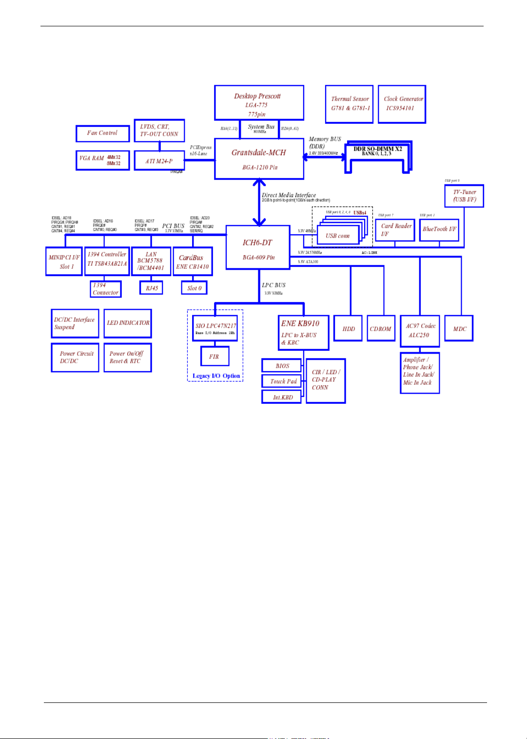
Block Diagram
4 Chapter 1
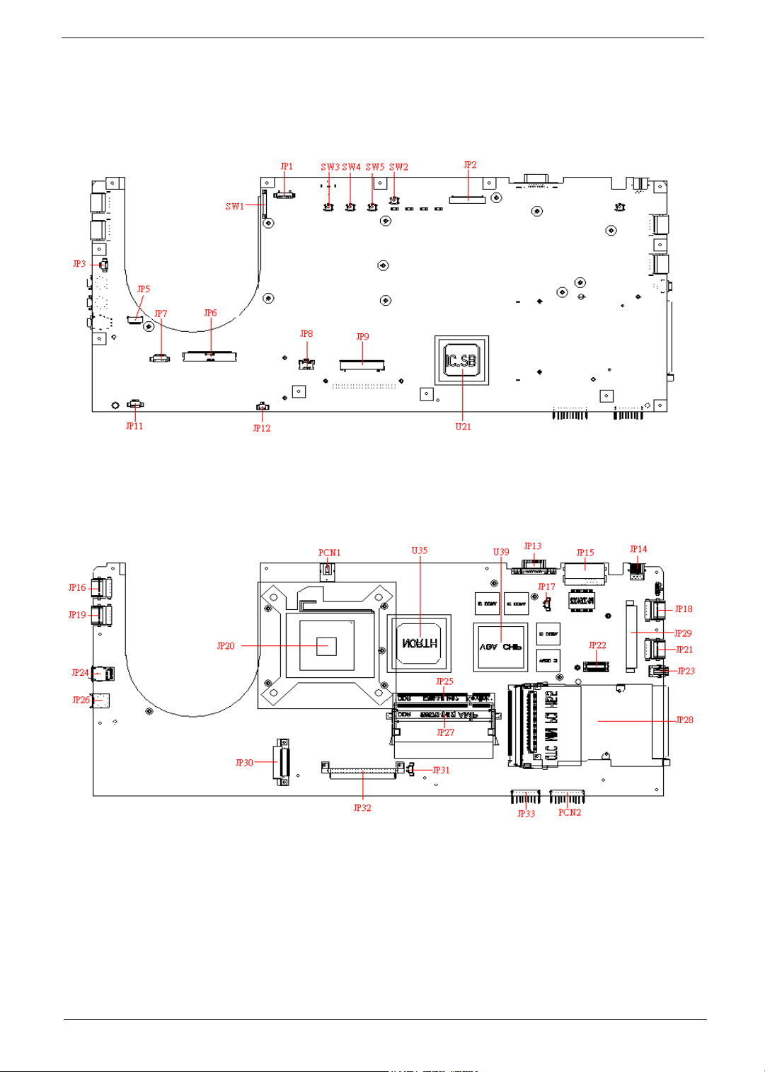
Mainboard Placement
Top View
Rear View
Chapter 1 5

ITEM DESCRIPTION ITEM DESCRIPTION
JP1/JP2 LVDS CONN. JP26 LINE IN CONN.
JP3/17/31 FAN CONN. JP27 DDR SO-DIMM0 CONN.
JP5 BLUETOOTH CONN. JP28 PCMCIA CONN.
JP6 LCM CONN. JP29 MINI-PCI CONN.
JP7 CARD READER CONN. JP30 ODD CONN.
JP8 TOUCH-PAD CONN. JP32 HDD CONN.
JP9 KEYBOARD CONN. JP33 TV-TUNER CONN.
JP11 SPEAKER CONN. PCN1 AC-IN CONN
JP12 SUBWOOFER CONN. PCN2 BATTERY CONN.
JP13 CRT CONN. SW1 LID SWITCH
JP14 TV-OUT CONN. SW2 E-MAIL BTN
JP15 RJ-11/RJ-45 CONN. SW3 USER BTN1
JP16/18/19/21 USB CONN. SW4 USER BTN2
JP20 CPU SOCKET SW5 INTERNET BTN
JP22 MDC CONN. U35 NORTH BRIDGE
JP23 1394 CONN. U21 SOUTH BRIDGE
JP24 LINE OUT CONN. U39 VGA CHIP
JP25 DDR SO-DIMM1 CONN.
6 Chapter 1
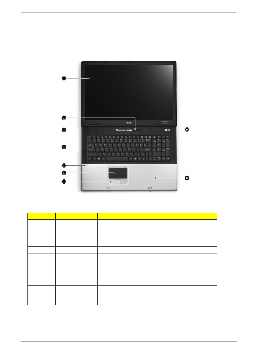
Outlook View
A general introduction of ports allow you to connect peripheral devices, as you would with a desktop PC.
Open View
# Item Description
1 Screen Wide scrren display provides visual output
2 Status Indicators LEDs that turn on and off to show system statuss.
3 Launch keys Buttons that can be programmed to start frequently used
applications.
4 Keyboard Full-size keyboard for inputting typed data.
5 Built-in Microphone For recording audio on the computer
6 Touchpad Touch sensitive pad that functions like a computer mouse.
7 Click buttons and 4-
way scroll key
8 Palm rest Provides a comfortable platform for your hands when typing
9 Power Button Turns the computer on or off.
Chapter 1 7
Right and left buttons that provide the same functions as the
buttons on a computer mouse. The scroll key scrolls the
contents of a window up and down, as well as right and left.
on the keyboard.
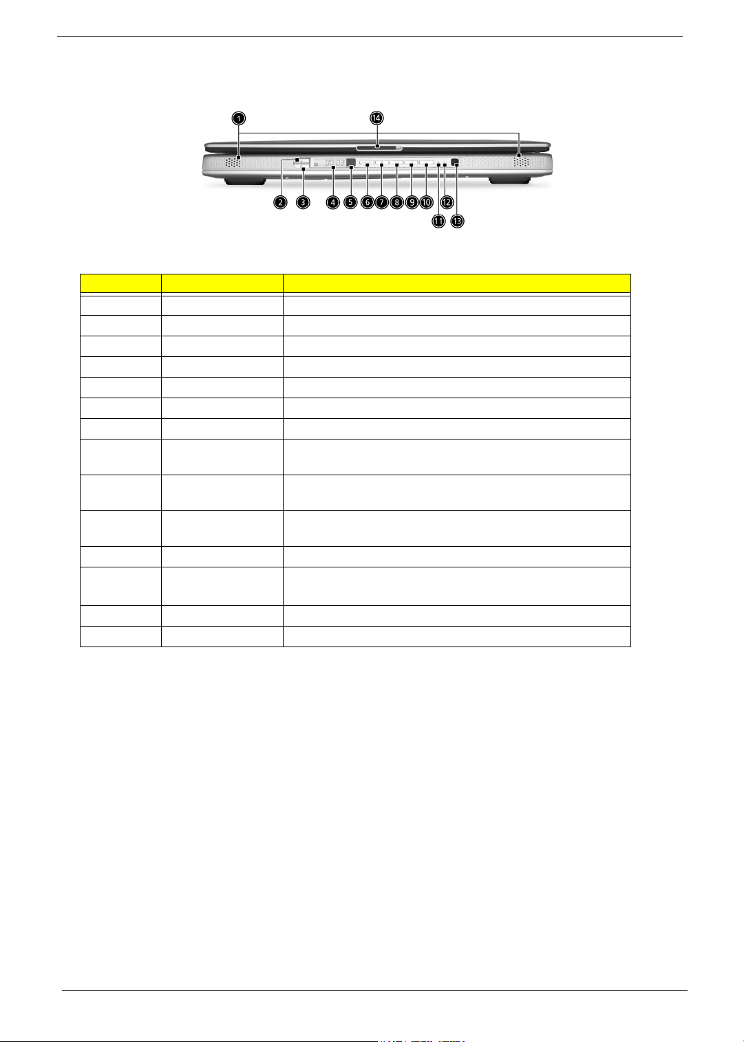
Front Panel
# Item Description
1 Stereo Speakers Produce stereo sound
2 InviLin
3 Bluetooth Button Enables BluetoothR functionality (manufacturing option)
4 Console display Media status display
5 Remote sensor Receive the signal from the remote control
6 Arcade button Multimedia button
7 Stop Press to stop playing the audio track or video file
8 Play/Pause Press to start playing the audio track or video file/Press again
9 Backward Press to skip backward to the previous track or video file and
10 Forward Press to skip forward to the next track or video file and start
11 Power indicator Lights when the computer is on
12 Battery charge
13 Media Controls Multimedia Button
14 Latch Locks and releases the lid
K Button Enables Wireless LAN connectivity (manufacturing option)
to pause
start playing
playing
Lights orange when the battery is in charging.
indicator
Lights green when the battery is fully charged
8 Chapter 1
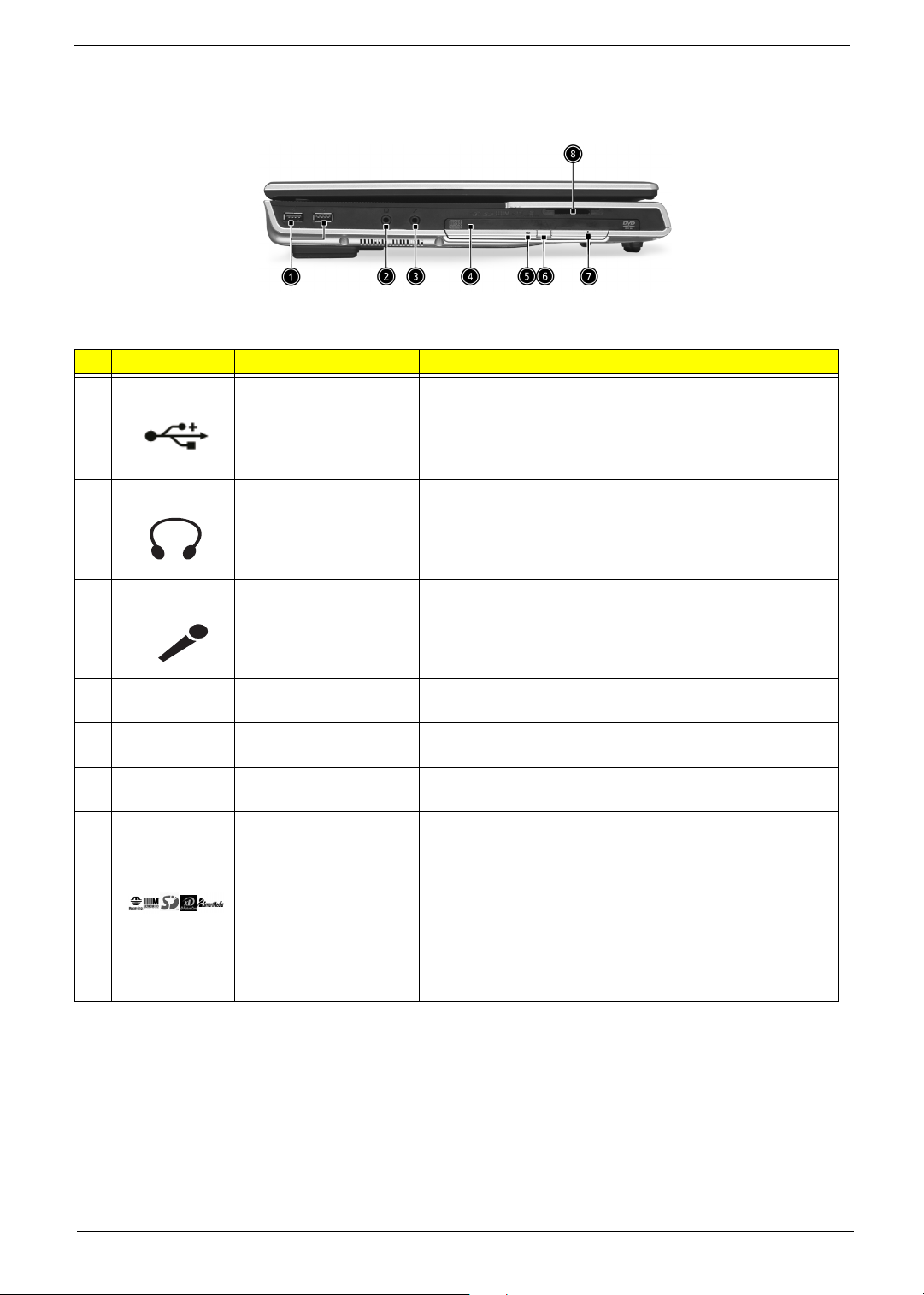
Left View
# Icon Item Description
1 USB ports USB 2.0 ports
2 Headphone-in jack Connects headphones for analog audio output and digital S/
PDIF output
3 Microphone-in jack Connects an external microphone for audio input
4 N/A Optical drive Internal optical drive; accepts CDs or DVDs depending on
the optical drive type
5 N/A Optical disc read
indicator
Light emitting diode (LED) that indicates when an optical
disc is being read
6 N/A Optical drive eject button Press the eject button to remove a disc from the optical
drive
7 N/A Optical drive emergency
Used to eject an optical disc when the computer is turned off
eject hole
8 5 in 1 Card Reader Supports:
T E Memory Stick (MS)
T MultiMediaCard (MMC)
T SecureDigital (SD)
T SmartMedia (SM)
T xD
Chapter 1 9
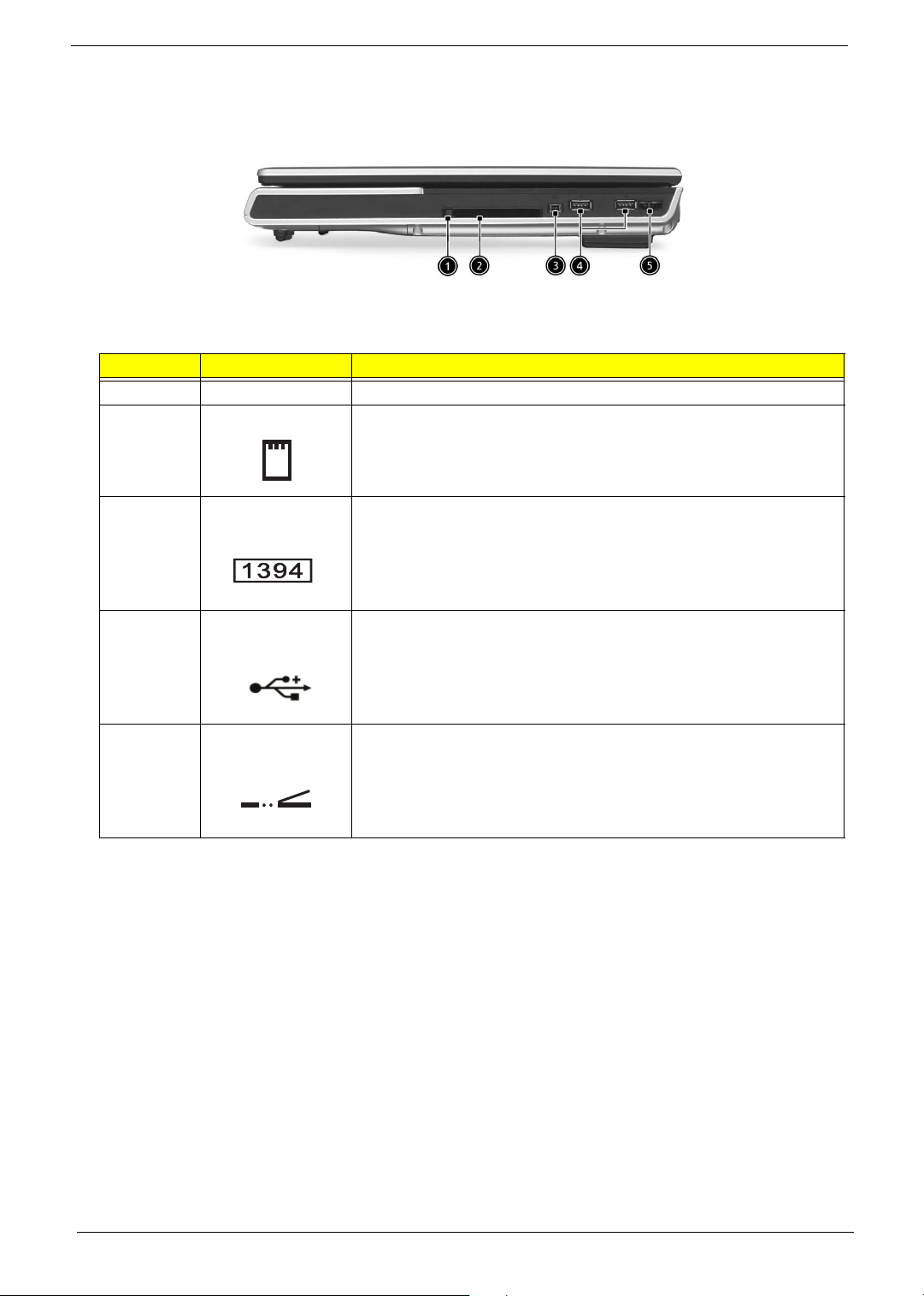
Right View
# Item Description
1 PC card eject button Press the eject button to remove a PC card from the PC card slot.
2 PC card slot Type II PC card supports PCMCIA or CardBus.
3 IEEE 1394 Port Connects IEEE 1394 devices.
4 USB Ports USB 2.0 ports
5 Infrared port Interfaces with infrared devices (e.g. infrared printer, IR-aware
computer, etc...)
10 Chapter 1
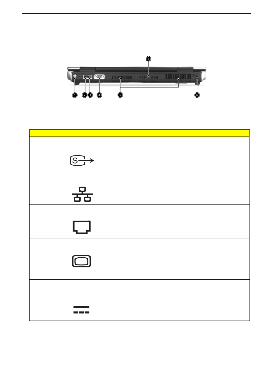
Rear View
# Item Description
1 S-video out port Connects to a television or display device supporting S-video input.
2 Network jack Connects the computer to the 10/100/1000 Ethernet network.
3 Modem Jack Connects the built-in fax/data modem to a phone line.
4 External display port Connects an external (VGA) monitor.
5 Ventilation slot Enables the computer to stay cool, even after prolonged use.
6 Kensington lock slot For attaching a security device.
7 DC-in jack Connect the AC power adapter
Chapter 1 11
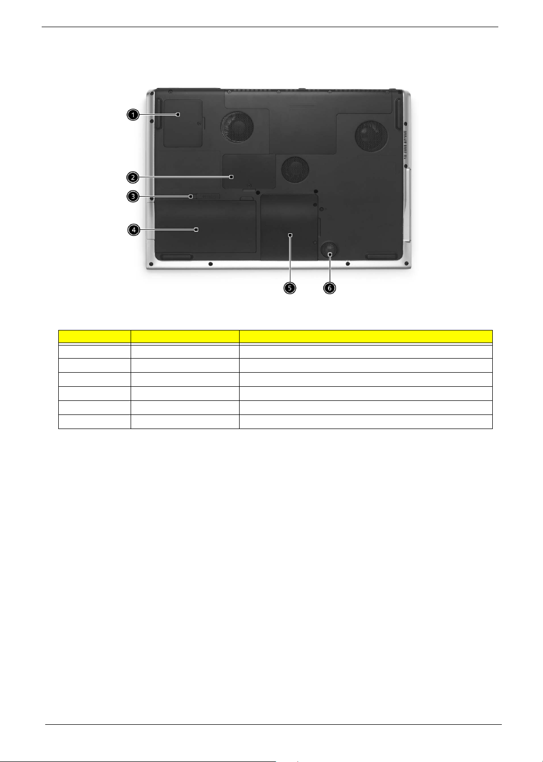
Bottom View
# Item Description
1 Mini-PCI Slot Slot for adding mini-PCI cards
2 Memory compartment Removable cover provides access to the
3 Battery release latch Unlatches the battery to remove the battery pack.
4 Battery pack The computer's removable battery.
5 Hard disk bay Removable cover provides access to the computer's hard drive.
6 Sub-Woofer Outputs low/mid range audio
12 Chapter 1
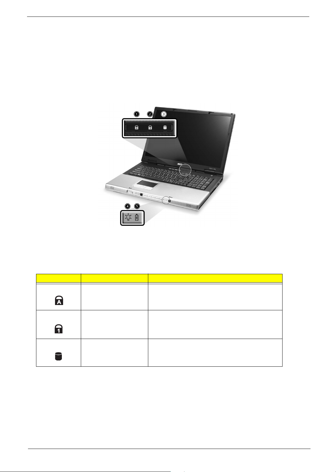
Indicators
Your computer provides an array of three indicators located above the keyboard, in addition to four
indicators positioned at the front of the palm rest area. These indicators show the status of the computer
and its componetns.
The three indicators located above the keyboard provide the following status information:
Icon Item Description
Caps Lock activity Lights when Caps Lock is activated.
Num Lock activiy Lights when Num Lock is activated.
Media activity Lights when the hard disk or optical drive is active.
NOTE: The keypad lock must be turned on to use the embedded numeric keypad.
Chapter 1 13
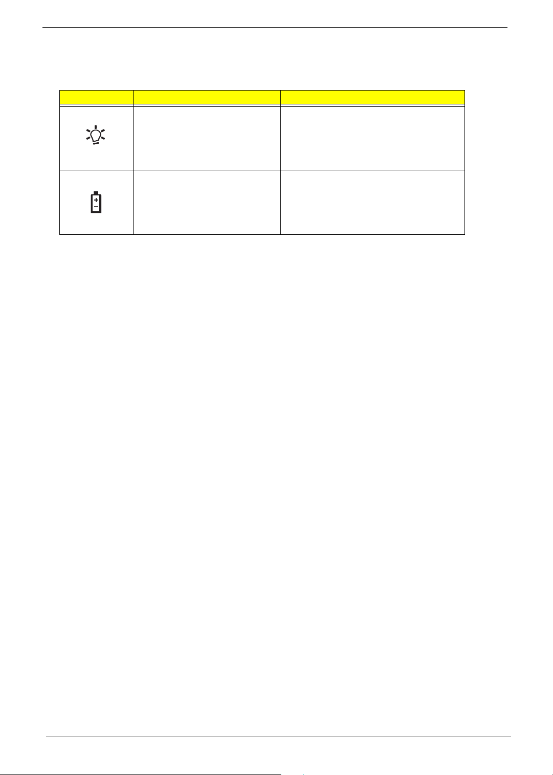
The four indicators located at the front of the unit provide the following status information:
Icon Item Description
Power mode Lights green when the computer is on and
lights orange when the computer is
in standby mode and lights flashing orange
when the computer is in hibernation.
Battery mode Lights green when the battery is fully
charged and lights orange when the battery
is in charged and lights flashing orange
when the battry power is low.
14 Chapter 1
Keyboard
The keyboard features full-size keys with an embedded keypad, separated cursor keys, two Windows
keys, and twelve function keys (hot keys).
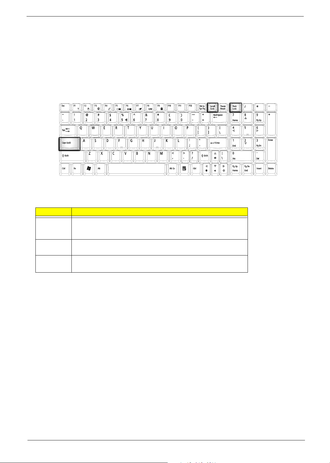
Special keys
Lock keys
The computer features three lock keys, each with its own status indicator light.
Lock Key Description
Caps Lock When Caps Lock is on, all alphabetic characters are typed in
uppercase. Toggle on and off by pressing the Caps Lock key on the left
side of the keyboard.
Num lock When Num Lock is on, the embedded numeric keyboard can be used.
Toggle on and off by pressing the Fn+tkeys simultaneously.
Scroll lock When Scroll Lock is on, the screen toggles up or down one line
at a time when the up and down cursor control keys are pressed.
NOTE: Scroll Lock doesn’t work in all applications. Toggle on and off by pressing the Fn+F12 keys
simultaneously.
Chapter 1 15
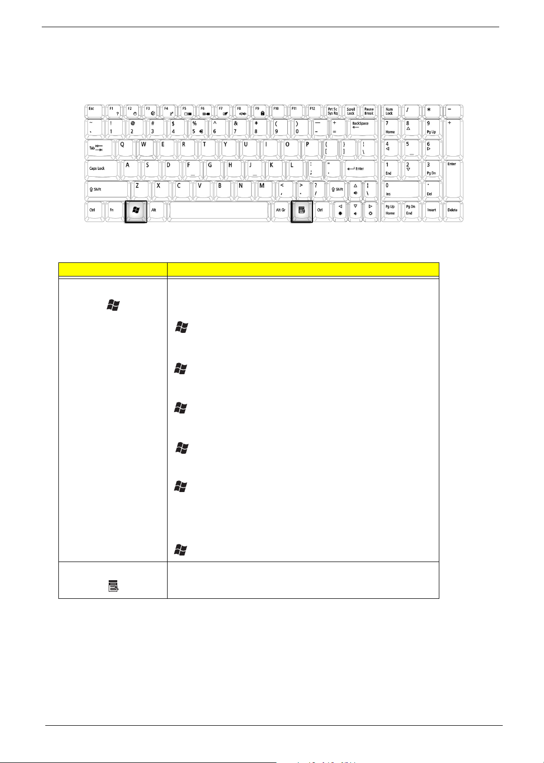
Windows Keys
The keyboard features two keys that perform Windows-specific functions.
Key Description
Windows logo key Pressed alone, this key has the same effect as clicking on the
Windows Start button; it launches the Start menu. It can also be
used with other keys to provide a variety of functions:
+ Tab (Activates the next Taskbar button)
+ E (Opens the My Computer window)
+ F1 (opens Help and Support)
+ F (opens the Find: All Files dialog box)
+ M (minimizes all windows)
j + Windows icon + M (undoes the minimize all windows
action)
+ R (opens the Run dialog box)
Application key This key has the same effect as clicking the right mouse button; it
opens the application’s context menu.
16 Chapter 1
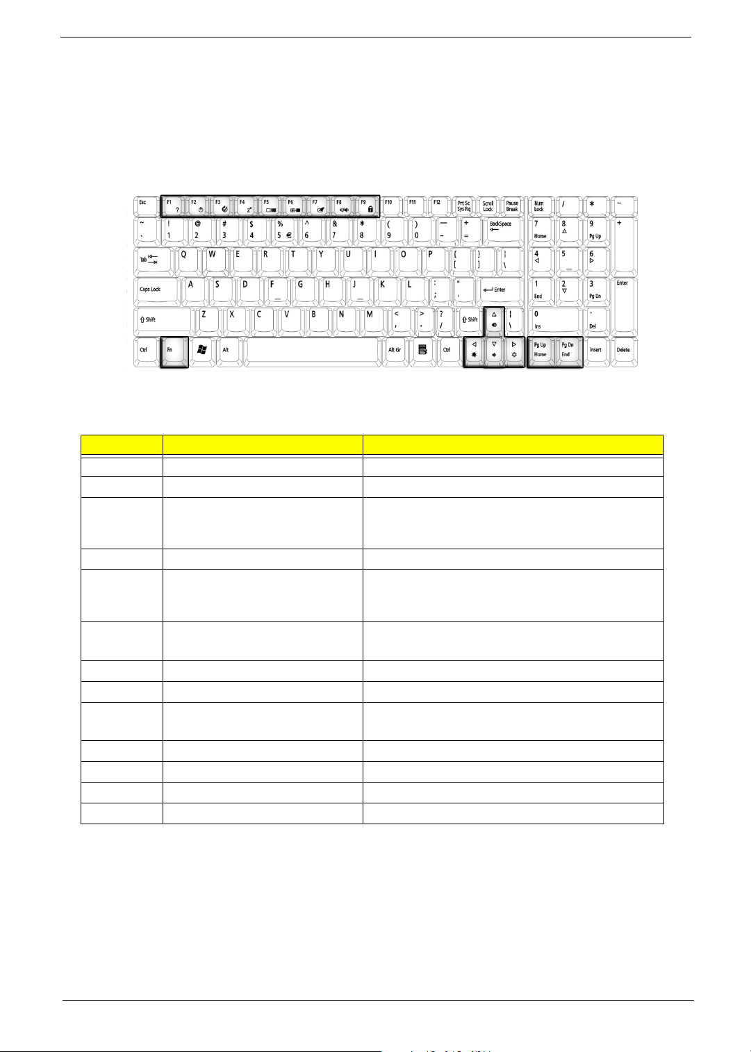
Function Keys
Using the Fn key with another key creates a hot key, providing a quick and convenient method for controlling
various functions.
To use a hot key, first hold down the Fn key. Next, press the second key in combination. Finally, release
both keys.
Your computer provides the following hot keys:
Hot Key Function Description
Fn+F1 Hot key help Displays help on hot keys
Fn+F2 Setup Access the computer’s configuration utility.
Fn+F3 Power management scheme
toggle
Fn+F4 Sleep Puts the computer in Sleep mode.
Fn+F5 Display toggle Switches display output between the display screen,
Fn+F6 Screen blank Turns the display screen backlight
Fn+F7 Touchpad toggle Turns the internal touchpad on and off.
Fn+F8 Speaker toggle Turns the speaker on and off.
Fn+Sub-
woofer key
Fn+w Volume up Increases the speaker volume.
Fn+y Volume down Decreases the speaker volume.
Fn+x Brightness up Increases the screen brightness.
Fn+z Brightness down Decreases the screen brightness.
Sub-woofer Turns the sub woofer on and off
Switches the power management scheme used by
the computer (function available if supported by
operating system).
external monitor ( if connected) and both the display
screen and external monitor.
off to save power. Press any key to return.
NOTE: When activating hotkeys, press and hold the Fn key before pressing the other key in the hotkey
combination.
Chapter 1 17
Fn F6
Fn F7
Fn F8
Fn
Fn
Fn
Fn
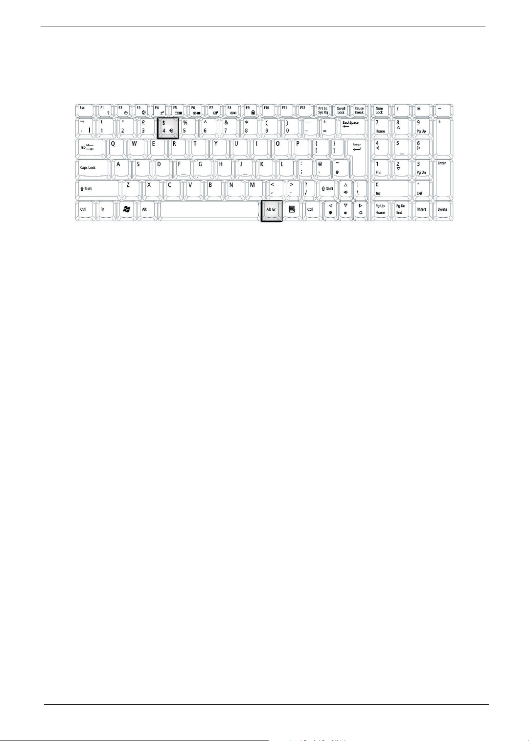
Euro key
Your computer supports the new Euro currency character. First, hold down the Alt Gr key, and then press the
Euro key.
18 Chapter 1
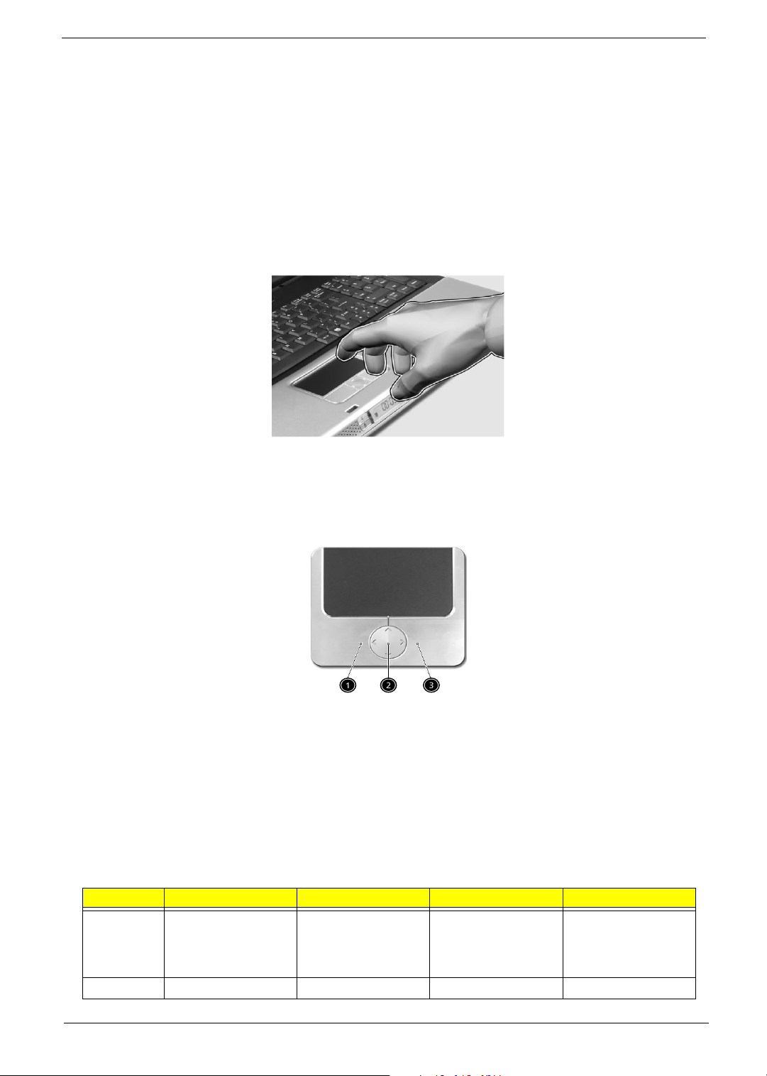
Touchpad
The build-in touchpad is a PS/2 compatible pointing device that senses movement on its surface.
The cursor responds to your finger movements on the touchpad. In addition, the two click buttons provide
the same functionality as a computer mouse, while the scroll key enables easy up and down scrolling in
documents and web pages.
The touchpad is located in the middle of the palm rest area, providing maximum comfort and efficiency.
Touchpad Basics
Use the touchpad as follows:
T Slide your finger over the surface of the touchpad to control the movement of the cursor. Tap the
touchpad to perform selection and execution functions.
T Press the left (1) and right (3) buttons to perform selection and execution functions, just as you
would use the buttons on a computer mouse.
T Use the scroll key (2) to scroll through long documents and web pages. Press the top of the key to
scroll up, and the bottom to scroll down; left to scroll left, and right to scroll right.
Function Left Button Righ Button 4-Way Scroll Way Ta p
Execute Click twice quickly Tap twice (at the
same speed as
double-clicking the
mouse button)
Select Click once Tap once
Chapter 1 19

Function Left Button Righ Button 4-Way Scroll Way Ta p
Drag Click and hold.
Then slide your
finger across the
touchpad to drag
the cursor over the
selection.
Access
context
menu
Scroll Click and hold the
NOTE: Keep your fingers, as well as the surface of the touchpad dry and clean. The touchpad is sensitive to
your finger movements: the lighter the touch, the better the response. Tapping hard will not increase the
touchpad’s responsiveness.
Click once
up/down/left/right
button
Tap twice quickly.
On the second tap,
slide your finger
across the
touchpad to drag
the cursor over the
selection.
20 Chapter 1
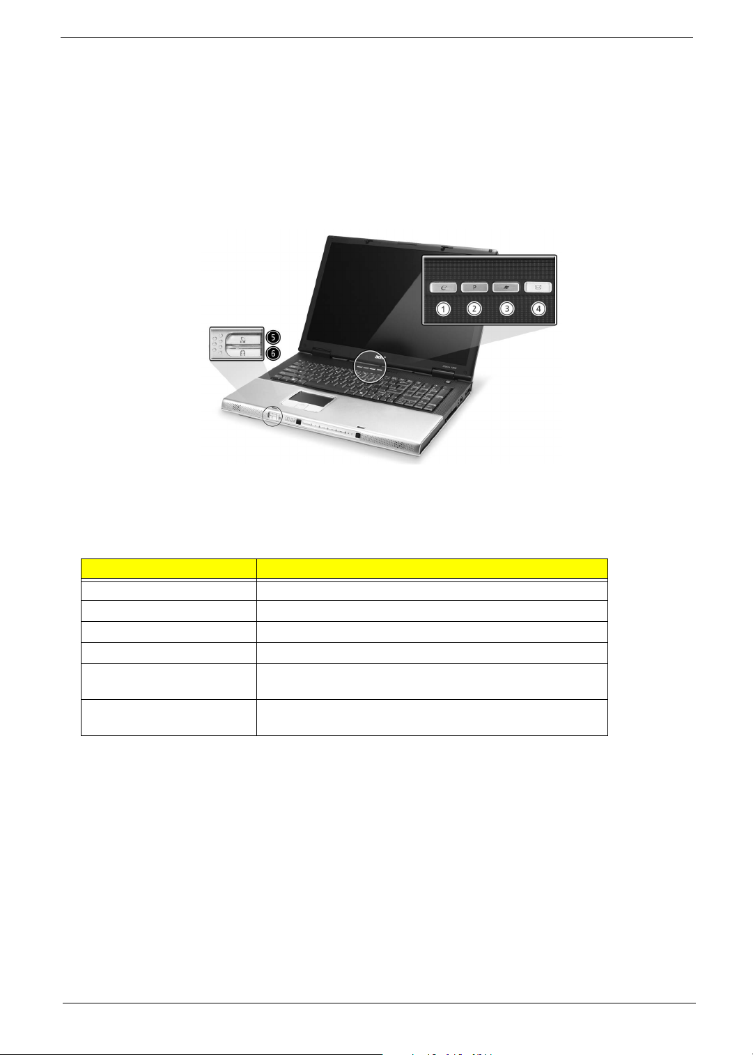
Launch Keys
Located at the top of the keyboard are four buttons, in addition to the power button. These buttons are
called launch keys. They are designed as key 1, key 2, key 3 and key 4, from right to left. By default,
key 1 is used to launch the email application and key 2 is used to launch the Internet browser. Key 3
and key 4 start the Launch Manager application. The first four launch keys can be set by the user. To set
the launch keys, run the Acer Launch Manager.
# Description
e Launches your email application.
P User-programmable
Web browser Internet browser application
Mail Email application
Wireless communication Lights to indicate the status of wireless LAN (optional)
communications.
Bluetooth communication Lights to indicate the status of Bluetooth (optional)
communications.
Chapter 1 21

Hardware Specifications and Configurations
Processor
Item Specification
CPU type
CPU package LGA775
CPU core voltage Depend on DVI
CPU I/O voltage 1.2V
BIOS
Item Specification
BIOS vendor Phoenix
BIOS Version Phoenix First BIOS
BIOS ROM type Flash ROM
BIOS ROM size 512KB
BIOS package 32 lead of TSSOP
BIOS password control Set by setup manual
Second Level Cache
Item Specification
Cache controller Built-in CPU
Cache size 1MB
1st level cache control Always enabled
2nd level cache control Always enabled
Cache scheme control Always enabled
Intel Prescott at 2.8~3.8GHz or faster
System Memory
Item Specification
Memory controller Intel Grantsdale 915P MCH
Memory size 128MB/256MB/512MB/1GB
DIMM socket number 2 slots
Supports memory size per slot 1024MB
Supports maximum memory size 2GB (by two 1024MB SO-DIMM module)
Supports DIMM type DDR Synchronous DRAM
Supports DIMM Speed 333MHz
Supports DIMM voltage 2.6V
Supports DIMM package 200-pin SO-DIMM
Memory module combinations You can install memory modules in any combinations as long as
they match the above specifications.
22 Chapter 1
 Loading...