

Acer ASPIRE 1700 Service Manual
Acer Aspire 1700 Series
Service Guide
Service guide files and updates are available
on the ACER/CSD web; for more information,
please refer to http://csd.acer.com.tw
PART NO.: VD.A08V7.001
PRINTED IN TAIWAN

Revision History
Please refer to the table below for the updates made on TravelMate 800 service guide.
Date Chapter Updates
2

Copyright
Copyright © 2003 by Acer Incorporated. All rights reserved. No part of this publication may be reproduced,
transmitted, transcribed, stored in a retrieval system, or translated into any language or computer language, in
any form or by any means, electronic, mechanical, magnetic, optical, chemical, manual or otherwise, without
the prior written permission of Acer Incorporated.
Disclaimer
The information in this guide is subject to change without notice.
Acer Incorporated makes no representations or warranties, either expressed or implied, with respect to the
contents hereof and specifically disclaims any warranties of merchantability or fitness for any particular
purpose. Any Acer Incorporated software described in this manual is sold or licensed "as is". Should the
programs prove defective following their purchase, the buyer (and not Acer Incorporated, its distributor, or its
dealer) assumes the entire cost of all necessary servicing, repair, and any incidental or consequential
damages resulting from any defect in the software.
Acer is a registered trademark of Acer Corporation.
Intel is a registered trademark of Intel Corporation.
Pentium and Pentium II/III are trademarks of Intel Corporation.
Other brand and product names are trademarks and/or registered trademarks of their respective holders.
3
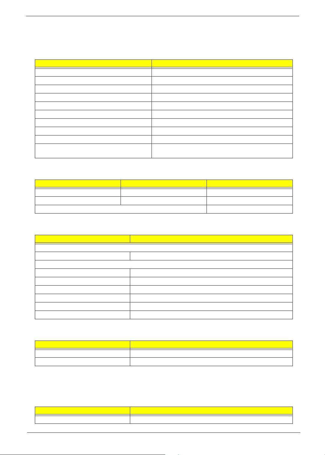
Conventions
The following conventions are used in this manual:
SCREEN MESSAGES Denotes actual messages that appear
on screen.
NOTE Gives bits and pieces of additional
information related to the current
topic.
WARNING Alerts you to any damage that might
result from doing or not doing specific
actions.
CAUTION Gives precautionary measures to
avoid possible hardware or software
problems.
IMPORTANT Reminds you to do specific actions
relevant to the accomplishment of
procedures.
4

Preface
Before using this information and the product it supports, please read the following general information.
1. This Service Guide provides you with all technical information relating to the BASIC CONFIGURATION
decided for Acer's "global" product offering. To better fit local market requirements and enhance product
competitiveness, your regional office MAY have decided to extend the functionality of a machine (e.g.
add-on card, modem, or extra memory capability). These LOCALIZED FEATURES will NOT be covered
in this generic service guide. In such cases, please contact your regional offices or the responsible
personnel/channel to provide you with further technical details.
2. Please note WHEN ORDERING FRU PARTS, that you should check the most up-to-date information
available on your regional web or channel. If, for whatever reason, a part number change is made, it will
not be noted in the printed Service Guide. For ACER-AUTHORIZED SERVICE PROVIDERS, your Acer
office may have a DIFFERENT part number code to those given in the FRU list of this printed Service
Guide. You MUST use the list provided by your regional Acer office to order FRU parts for repair and
service of customer machines.
5

6

Table of Contents
Chapter 1 System Specifications 1
Overview . . . . . . . . . . . . . . . . . . . . . . . . . . . . . . . . . . . . . . . . . . . . . . . . . . . . . . . . . . 1
Features . . . . . . . . . . . . . . . . . . . . . . . . . . . . . . . . . . . . . . . . . . . . . . . . . . . . . . . . . . 2
Outlook . . . . . . . . . . . . . . . . . . . . . . . . . . . . . . . . . . . . . . . . . . . . . . . . . . . . . . . . . . . 3
Main Board Layout . . . . . . . . . . . . . . . . . . . . . . . . . . . . . . . . . . . . . . . . . . . . . . . . . . 9
Hardware Specifications and Configurations . . . . . . . . . . . . . . . . . . . . . . . . . . . . . 10
Power Management Function (ACPI support function) . . . . . . . . . . . . . . . . . . . . . 18
BIOS Setup Utility . . . . . . . . . . . . . . . . . . . . . . . . . . . . . . . . . . . . . . . . . . . . . . . . . . 19
Chapter 2 System Utilities 19
Navigating the BIOS Utility . . . . . . . . . . . . . . . . . . . . . . . . . . . . . . . . . . . . . . . 20
Info. . . . . . . . . . . . . . . . . . . . . . . . . . . . . . . . . . . . . . . . . . . . . . . . . . . . . . . . . . 21
Main . . . . . . . . . . . . . . . . . . . . . . . . . . . . . . . . . . . . . . . . . . . . . . . . . . . . . . . . 22
System Devices . . . . . . . . . . . . . . . . . . . . . . . . . . . . . . . . . . . . . . . . . . . . . . . 24
Security . . . . . . . . . . . . . . . . . . . . . . . . . . . . . . . . . . . . . . . . . . . . . . . . . . . . . . 25
Boot . . . . . . . . . . . . . . . . . . . . . . . . . . . . . . . . . . . . . . . . . . . . . . . . . . . . . . . . . 28
Exit . . . . . . . . . . . . . . . . . . . . . . . . . . . . . . . . . . . . . . . . . . . . . . . . . . . . . . . . . 29
Chapter 3 Machine Disassembly and Replacement 31
General Information . . . . . . . . . . . . . . . . . . . . . . . . . . . . . . . . . . . . . . . . . . . . . . . . 32
Before You Begin . . . . . . . . . . . . . . . . . . . . . . . . . . . . . . . . . . . . . . . . . . . . . . 32
Disassembly Procedure Flowchart . . . . . . . . . . . . . . . . . . . . . . . . . . . . . . . . . . . . . 33
Disassembling . . . . . . . . . . . . . . . . . . . . . . . . . . . . . . . . . . . . . . . . . . . . . . . . . . . . 36
Remove the battery . . . . . . . . . . . . . . . . . . . . . . . . . . . . . . . . . . . . . . . . . . . . . 36
Remove the HDD module . . . . . . . . . . . . . . . . . . . . . . . . . . . . . . . . . . . . . . . . 36
Remove the combo drive . . . . . . . . . . . . . . . . . . . . . . . . . . . . . . . . . . . . . . . . 36
Remove the thermal module . . . . . . . . . . . . . . . . . . . . . . . . . . . . . . . . . . . . . . 37
Remove CPU . . . . . . . . . . . . . . . . . . . . . . . . . . . . . . . . . . . . . . . . . . . . . . . . . 37
Remove the memory . . . . . . . . . . . . . . . . . . . . . . . . . . . . . . . . . . . . . . . . . . . . 37
Remove VGA card . . . . . . . . . . . . . . . . . . . . . . . . . . . . . . . . . . . . . . . . . . . . . 37
Detach the wireless card . . . . . . . . . . . . . . . . . . . . . . . . . . . . . . . . . . . . . . . . . 38
Remove moden card . . . . . . . . . . . . . . . . . . . . . . . . . . . . . . . . . . . . . . . . . . . . 38
Remove the inverter cover . . . . . . . . . . . . . . . . . . . . . . . . . . . . . . . . . . . . . . . 38
Detach the upper system cover . . . . . . . . . . . . . . . . . . . . . . . . . . . . . . . . . . . 39
Remove the LCD module . . . . . . . . . . . . . . . . . . . . . . . . . . . . . . . . . . . . . . . . 39
Remove the LCD panel . . . . . . . . . . . . . . . . . . . . . . . . . . . . . . . . . . . . . . . . . . 40
Remove the inverter board . . . . . . . . . . . . . . . . . . . . . . . . . . . . . . . . . . . . . . . 40
Remove the mylars . . . . . . . . . . . . . . . . . . . . . . . . . . . . . . . . . . . . . . . . . . . . . 42
Remove the wireless module . . . . . . . . . . . . . . . . . . . . . . . . . . . . . . . . . . . . . 42
Remove the side bracket 42
Remove the LED cable attached on the LCD outer shield. . . . . . . . . . . . . . . . 43
Remove the subwoofer . . . . . . . . . . . . . . . . . . . . . . . . . . . . . . . . . . . . . . . . . . 43
Release the MDC cable. . . . . . . . . . . . . . . . . . . . . . . . . . . . . . . . . . . . . . . . . . 44
Disconnect the cable to the modem header. . . . . . . . . . . . . . . . . . . . . . . . . . 44
Remove the keyboard . . . . . . . . . . . . . . . . . . . . . . . . . . . . . . . . . . . . . . . . . . . 44
Remove the LED board . . . . . . . . . . . . . . . . . . . . . . . . . . . . . . . . . . . . . . . . . 44
Detach the front panel . . . . . . . . . . . . . . . . . . . . . . . . . . . . . . . . . . . . . . . . . . . 45
Remove the Audio DJ board . . . . . . . . . . . . . . . . . . . . . . . . . . . . . . . . . . . . . . 45
Remove the touch pad . . . . . . . . . . . . . . . . . . . . . . . . . . . . . . . . . . . . . . . . . . 46
Remove the touch pad board . . . . . . . . . . . . . . . . . . . . . . . . . . . . . . . . . . . . . 47
Remove the lid switch cable . . . . . . . . . . . . . . . . . . . . . . . . . . . . . . . . . . . . . . 47
Remove the floppy drive . . . . . . . . . . . . . . . . . . . . . . . . . . . . . . . . . . . . . . . . . 47
Remove the speaker set . . . . . . . . . . . . . . . . . . . . . . . . . . . . . . . . . . . . . . . . . 48
Remove the mainboard . . . . . . . . . . . . . . . . . . . . . . . . . . . . . . . . . . . . . . . . . . 48
VII

Table of Contents
Remove the system fan . . . . . . . . . . . . . . . . . . . . . . . . . . . . . . . . . . . . . . . . . 49
FDD Module . . . . . . . . . . . . . . . . . . . . . . . . . . . . . . . . . . . . . . . . . . . . . . . . . . 50
HDD Module . . . . . . . . . . . . . . . . . . . . . . . . . . . . . . . . . . . . . . . . . . . . . . . . . . 50
Combo Module . . . . . . . . . . . . . . . . . . . . . . . . . . . . . . . . . . . . . . . . . . . . . . . . 51
General Information . . . . . . . . . . . . . . . . . . . . . . . . . . . . . . . . . . . . . . . . . . . . . . . . 54
Before You Begin . . . . . . . . . . . . . . . . . . . . . . . . . . . . . . . . . . . . . . . . . . . . . . 54
Re-assembly 55
Place the system fan . . . . . . . . . . . . . . . . . . . . . . . . . . . . . . . . . . . . . . . . . . . . 55
Re-assembling the mainboard . . . . . . . . . . . . . . . . . . . . . . . . . . . . . . . . . . . . 55
Place the speaker set back to position . . . . . . . . . . . . . . . . . . . . . . . . . . . . . . 56
Place the floppy module back to position . . . . . . . . . . . . . . . . . . . . . . . . . . . . 57
Place the touch pad back to position . . . . . . . . . . . . . . . . . . . . . . . . . . . . . . . 57
Reconnect the Audio DJ board . . . . . . . . . . . . . . . . . . . . . . . . . . . . . . . . . . . . 58
Place the system cover back to position . . . . . . . . . . . . . . . . . . . . . . . . . . . . . 58
Reconnect the LED cable . . . . . . . . . . . . . . . . . . . . . . . . . . . . . . . . . . . . . . . . 59
Place the keyboard back to position . . . . . . . . . . . . . . . . . . . . . . . . . . . . . . . . 59
Place the MDC cable back to position . . . . . . . . . . . . . . . . . . . . . . . . . . . . . . 60
Reconnect the sub-woofer . . . . . . . . . . . . . . . . . . . . . . . . . . . . . . . . . . . . . . . 60
Place the LED cable back to position . . . . . . . . . . . . . . . . . . . . . . . . . . . . . . . 60
Place the side mount back to position. . . . . . . . . . . . . . . . . . . . . . . . . . . . . . . 61
Place the wireless antenna back to position . . . . . . . . . . . . . . . . . . . . . . . . . . 61
Reattach the LCD cable . . . . . . . . . . . . . . . . . . . . . . . . . . . . . . . . . . . . . . . . . 62
Place the inverter board back to position . . . . . . . . . . . . . . . . . . . . . . . . . . . . 62
Re-assembling the LCD module . . . . . . . . . . . . . . . . . . . . . . . . . . . . . . . . . . . 63
Place the system cover and hinge back to position . . . . . . . . . . . . . . . . . . . . 64
Place the inverter cover back to position . . . . . . . . . . . . . . . . . . . . . . . . . . . . 64
Reconnect the cable to the MDC card and wireless card . . . . . . . . . . . . . . . . 64
Place the VGA card back to position. . . . . . . . . . . . . . . . . . . . . . . . . . . . . . . . 65
Insert the memory . . . . . . . . . . . . . . . . . . . . . . . . . . . . . . . . . . . . . . . . . . . . . . 65
Place the CPU back . . . . . . . . . . . . . . . . . . . . . . . . . . . . . . . . . . . . . . . . . . . . 66
Place the thermal module back to position . . . . . . . . . . . . . . . . . . . . . . . . . . . 66
Place the floppy back to position . . . . . . . . . . . . . . . . . . . . . . . . . . . . . . . . . . 66
Reconnect the HDD power and coaxial cable. . . . . . . . . . . . . . . . . . . . . . . . . 66
Place the battery or dummy battery back to position. . . . . . . . . . . . . . . . . . . . 67
Place the bottom shield back to position. . . . . . . . . . . . . . . . . . . . . . . . . . . . . 67
FDD Module . . . . . . . . . . . . . . . . . . . . . . . . . . . . . . . . . . . . . . . . . . . . . . . . . . 68
HDD Module . . . . . . . . . . . . . . . . . . . . . . . . . . . . . . . . . . . . . . . . . . . . . . . . . . 68
Combo Module . . . . . . . . . . . . . . . . . . . . . . . . . . . . . . . . . . . . . . . . . . . . . . . . 69
Chapter 4 Troubleshooting 71
System Check Procedures . . . . . . . . . . . . . . . . . . . . . . . . . . . . . . . . . . . . . . . . . . . 72
External Diskette Drive Check . . . . . . . . . . . . . . . . . . . . . . . . . . . . . . . . . . . . 72
External CD-ROM Drive Check . . . . . . . . . . . . . . . . . . . . . . . . . . . . . . . . . . . 72
Keyboard or Auxiliary Input Device Check . . . . . . . . . . . . . . . . . . . . . . . . . . . 72
Memory check . . . . . . . . . . . . . . . . . . . . . . . . . . . . . . . . . . . . . . . . . . . . . . . . . 73
Power System Check . . . . . . . . . . . . . . . . . . . . . . . . . . . . . . . . . . . . . . . . . . . 73
Touchpad check . . . . . . . . . . . . . . . . . . . . . . . . . . . . . . . . . . . . . . . . . . . . . . . 74
Power-On Self-Test (POST) Error Message . . . . . . . . . . . . . . . . . . . . . . . . . . . . . 75
Index of Error Messages . . . . . . . . . . . . . . . . . . . . . . . . . . . . . . . . . . . . . . . . . . . . . 76
Index of Symptom-to-FRU Error Message . . . . . . . . . . . . . . . . . . . . . . . . . . . . . . . 78
Intermittent Problems . . . . . . . . . . . . . . . . . . . . . . . . . . . . . . . . . . . . . . . . . . . . . . . 82
Undetermined Problems . . . . . . . . . . . . . . . . . . . . . . . . . . . . . . . . . . . . . . . . . . . . . 83
Aspire 1700 Jumpers and Connectors . . . . . . . . . . . . . . . . . . . . . . . . . . . . . . . . . . 85
VIII

Table of Contents
Chapter 5 Jumper and Connector Locations 85
Top view . . . . . . . . . . . . . . . . . . . . . . . . . . . . . . . . . . . . . . . . . . . . . . . . . . . . . 85
Connector Description . . . . . . . . . . . . . . . . . . . . . . . . . . . . . . . . . . . . . . . . . . 86
Bottom View . . . . . . . . . . . . . . . . . . . . . . . . . . . . . . . . . . . . . . . . . . . . . . . . . . 87
Connector Description . . . . . . . . . . . . . . . . . . . . . . . . . . . . . . . . . . . . . . . . . . 88
Chapter 6 FRU List 89
Exploded Diagram . . . . . . . . . . . . . . . . . . . . . . . . . . . . . . . . . . . . . . . . . . . . . . . . . 89
The System . . . . . . . . . . . . . . . . . . . . . . . . . . . . . . . . . . . . . . . . . . . . . . . . . . . 89
LCD 17” ASSY . . . . . . . . . . . . . . . . . . . . . . . . . . . . . . . . . . . . . . . . . . . . . . . . 90
FDD ASSY . . . . . . . . . . . . . . . . . . . . . . . . . . . . . . . . . . . . . . . . . . . . . . . . . . . 90
HDD ASSY . . . . . . . . . . . . . . . . . . . . . . . . . . . . . . . . . . . . . . . . . . . . . . . . . . . 91
ODD ASSY . . . . . . . . . . . . . . . . . . . . . . . . . . . . . . . . . . . . . . . . . . . . . . . . . . . 91
FRU List . . . . . . . . . . . . . . . . . . . . . . . . . . . . . . . . . . . . . . . . . . . . . . . . . . . . . . . . . 93
Appendix A Model Definition and Configuration 100
Aspire 1700 Series . . . . . . . . . . . . . . . . . . . . . . . . . . . . . . . . . . . . . . . . . . . . . . . . 100
Main Features . . . . . . . . . . . . . . . . . . . . . . . . . . . . . . . . . . . . . . . . . . . . . . . . . . . . 101
Appendix B Test Compatible Components 103
Microsoft® Windows® XP Environment Test . . . . . . . . . . . . . . . . . . . . . . . . . . . . 104
Appendix C Online Support Information 109
IX

Table of Contents
X

System Specifications
Overview
Aspire 1700 is designed to be a mobile desktop. It can support Intel Pentium 4 Northwood as well as Intel
Celeron with front side bus 400MHz or 533MHz. The LCD panel ranges from 15” to 17” and the capacity is
built to be below 6 litters.
Chapter 1
Chapter 1 1

Features
Performance
T Intel Pentium 4 Northwood 1.8~3.06 GHz/Celeron processor
T L2 cache 512k (Northwood), 128K (Celeron)
T SiS M650 with SiS 962, support 400/533MHz Bus, HTT support.
T 20GB or higher capacity Desktop 5400rpm, 7200rpm HDD
T Microsoft XP OS
T Optional 6-in-1 Multimedia memory card module.
Multimedia
T CD-ROM
T DVD-ROM
T DVD/CD-RW combo
T Audio input and output jacks
T Optional 6-in-1 Multimedia memory card module
T Hardware 3D graphic engine
T Two stereo speakers + One sub-woofer
T 15” Desktop XGA and 17” Desktop SXGA.
Connectivity
T Modem: Software Modem V9.0/V9.2 56Kbps (MDC)
T 10/100 LAN
T Optional Mini-PCI 802.11b/802.11a+b/bluetooth
T One switch for on/off of wireless
T Keyboard and touchpad with 4 way scroll buttons
T 4 universal serial bus (USB) ports.
Human-centric design and ergonomics
T Rugged and space saving
T Full size desktop keyboard
2 Chapter 1
Outlook
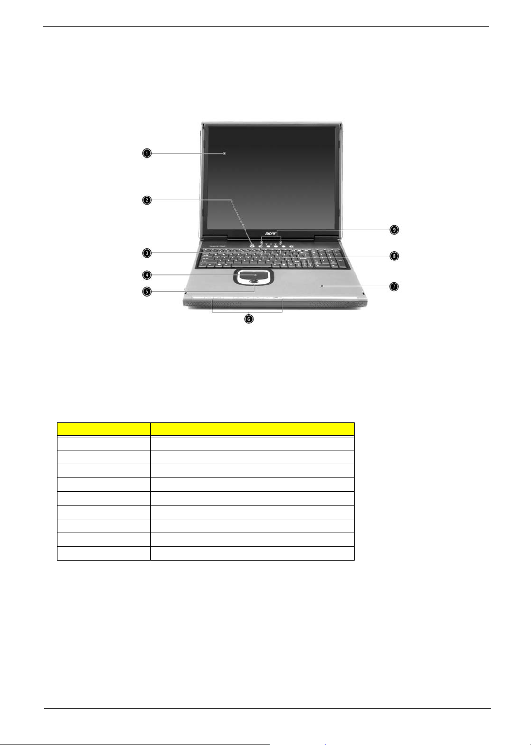
Opened Front View
Label Description
1 Display
2 Power button
3 Keyboard
4 Touchpad
5 Click button & scroll key
6 Audio DJ controls and indicator
7Palm rest
8 Launch keys
9 Status indicators
Chapter 1 3

Closed Front view
# Item Description
1 Speakers Left and right speakers deliver stereo audio output
2 Wireless
communication
indicator
3 Power indicator Lights when the computer is on.
Lights when the Wireless LAN capability is enabled.
4 Chapter 1
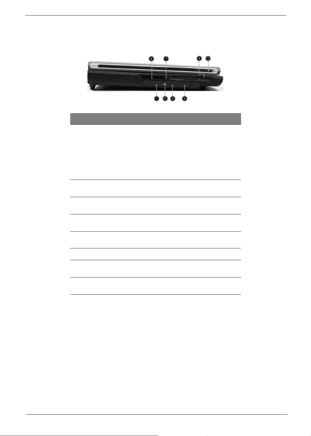
Left view
# Item Descr ipt ion
1 Optical drive Depending on your model, the optical drive
2 Optical disc read indicator Light emitting diode (LED) that indicates
3 Optical drive eject button Press the eject button to remove a disc from
4 Optical drive emergency
eject hole
Left Latch Locks and releases the lid.(One on the right
5
Floppy drive Accepts 3.5 inch floppy disk.
6
7 PC card eject button Press the eject button to remove a PC card
8 PC card slot The slot supports a standard Type II PC card
is one of the following:
• CD-ROM drive for reading CDs.
DVD-ROM drive for reading CDs and
DVDs.
DVD/CD-RW combo drive for reading
CDs and DVDs, and writing to CD-Rs
and CD-RWs..
when an optical disc is being read.
the optical drive.
Used to eject an optical disc when the
computer is turned off.
and one on the left)
from the PC card slot.
(PCM CIA).
•
•
Chapter 1 5
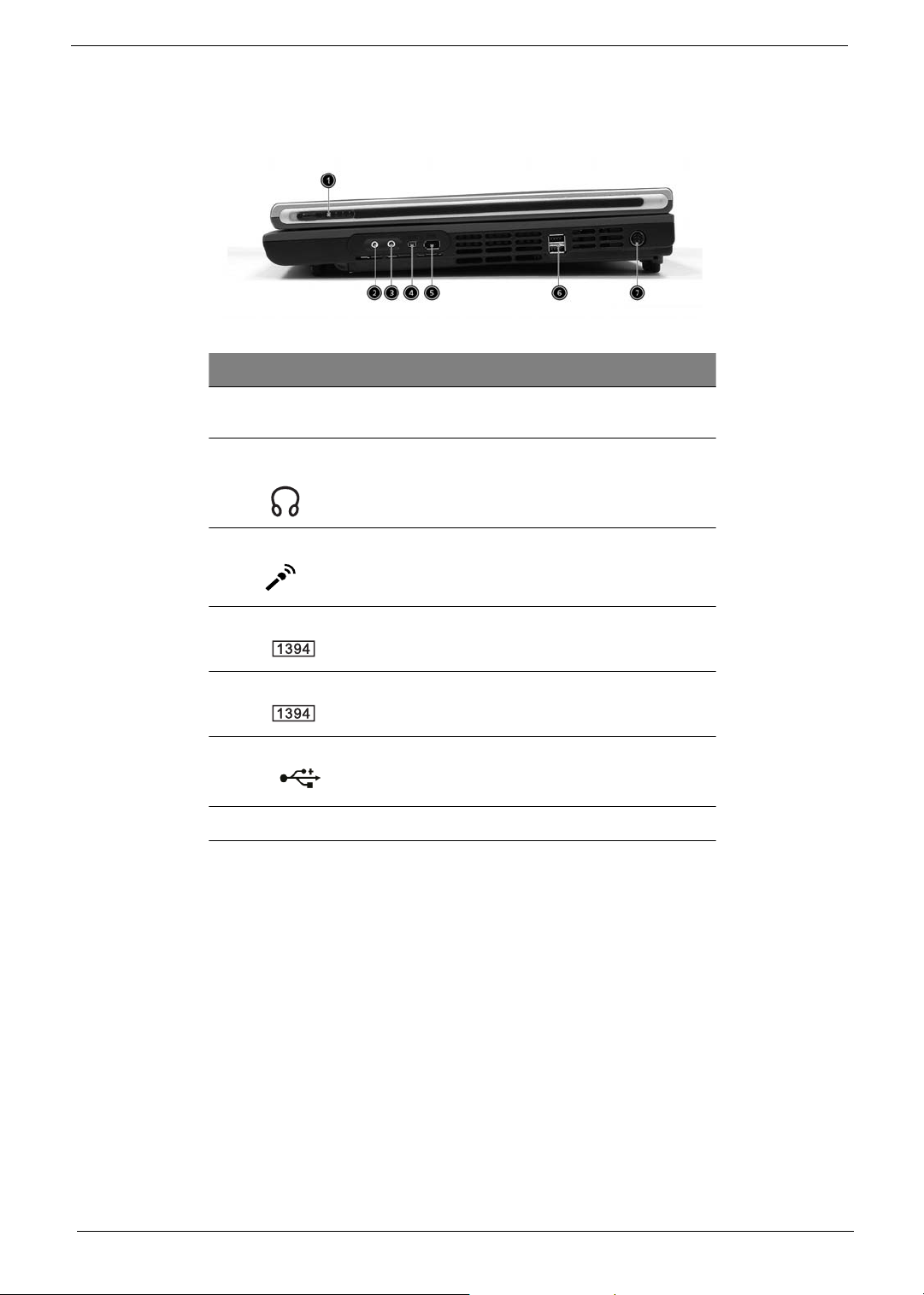
Right view
# Item Description
1 Right Latch Locks and releases the lid.(One on the right
and one on the left)
2 Speaker/Headphone-out
jack
3 Line-in/Mic-in jack Accepts audio line-in devices (e.g., audio CD
4 IEEE 1394 port
5 IEEE 1394 port
6 USB ports
7 DC-in jack Connects the AC adapter.
Connects to audio line-out devices
(e.g.,speakers, headphones).
player, stereo walkman). Selection is through
the OS Windows mixer.
Connects to an IEEE 1394 device.
Connects to an IEEE 1394 device.
2 ports for connecting USB 2.0 devices.
6 Chapter 1
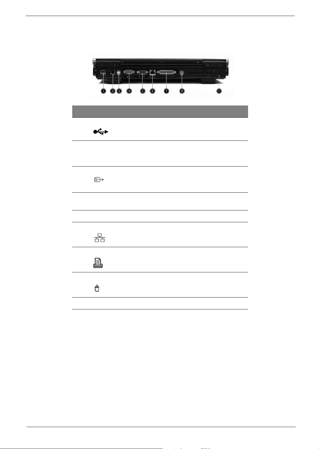
Rear view
# Item Descr ipt ion
1 USB ports 2 ports for connecting USB 2. 0 devices.
2Modem jack Connects the built-in fax/data modem to a phone
3S-video
4 External display port Connects an external (VGA) display devices
5 COM port Connects to other serial interface devices.
6 Network jack Connects to an Ethernet 10/100-based network.
7 Parallel port Connects a parallel device, such as a printer.
8 PS2 port C onnects to a PS2 mouse/ keyboard
9 Kensington lock slot For attaching a security connector.
line.
Connects to a television or dispaly device with Svideo input.
monitor.
Chapter 1 7
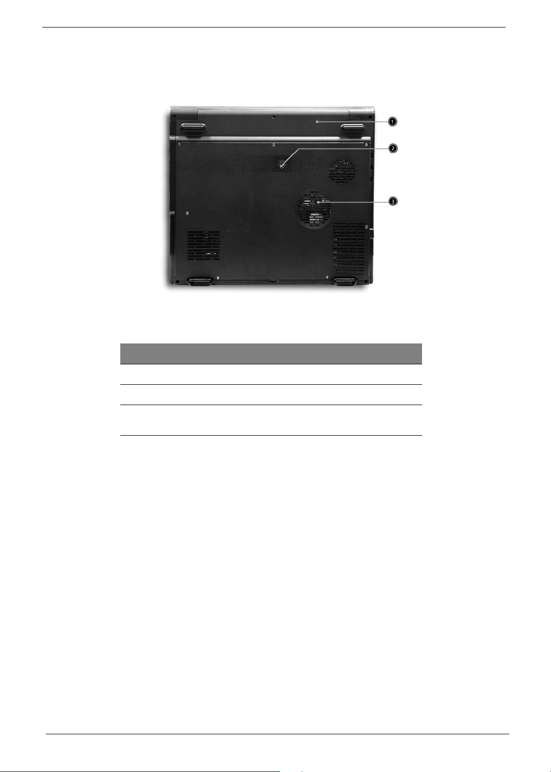
Bottom view
# Item Description
1 Battery cover Protects the battery bay.
2 Sub-woofer Enhance the audio quality.
3 Ventilation slots Enables the computer to stay cool, even after
prolonged use.
8 Chapter 1
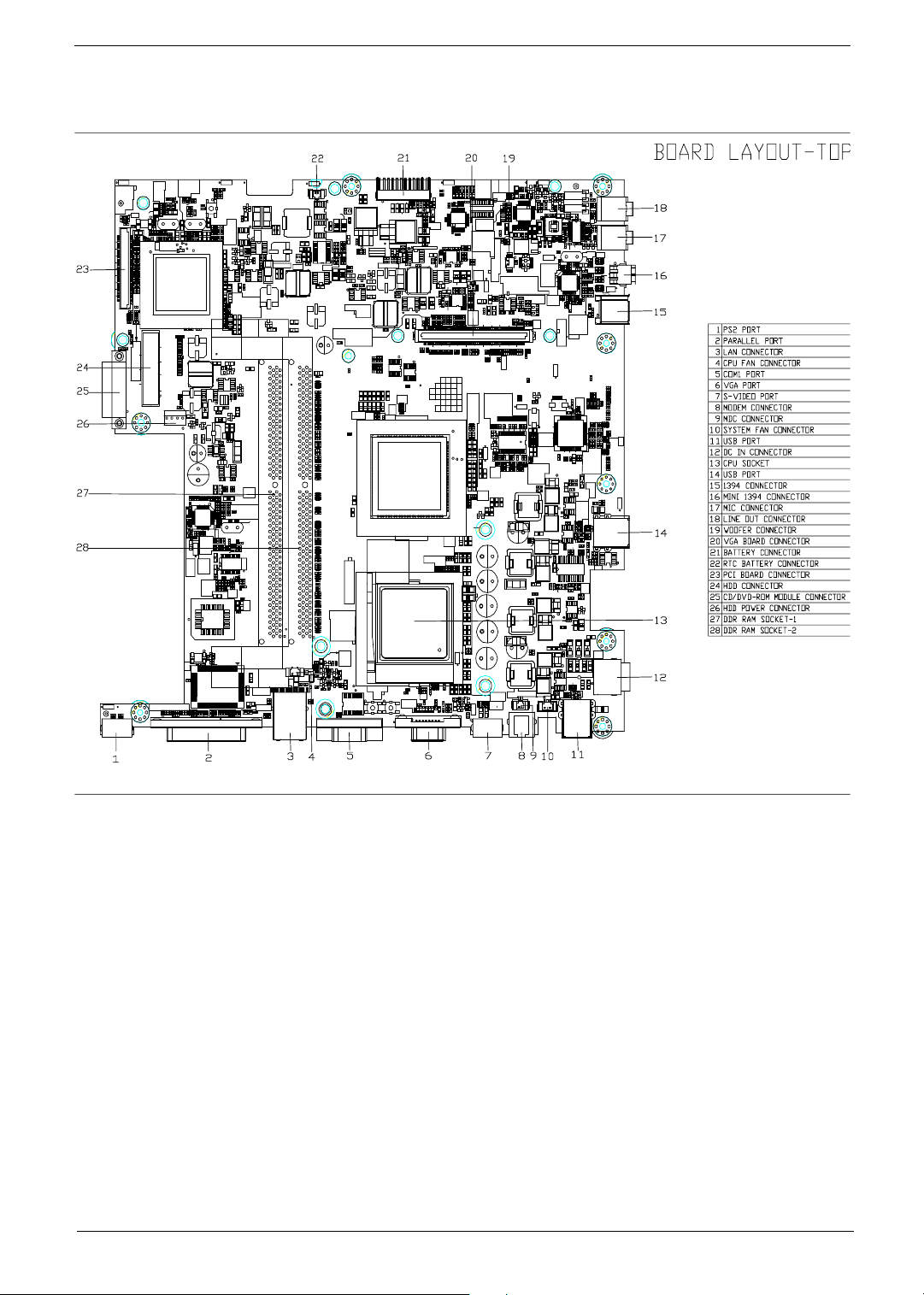
Main Board Layout
Chapter 1 9
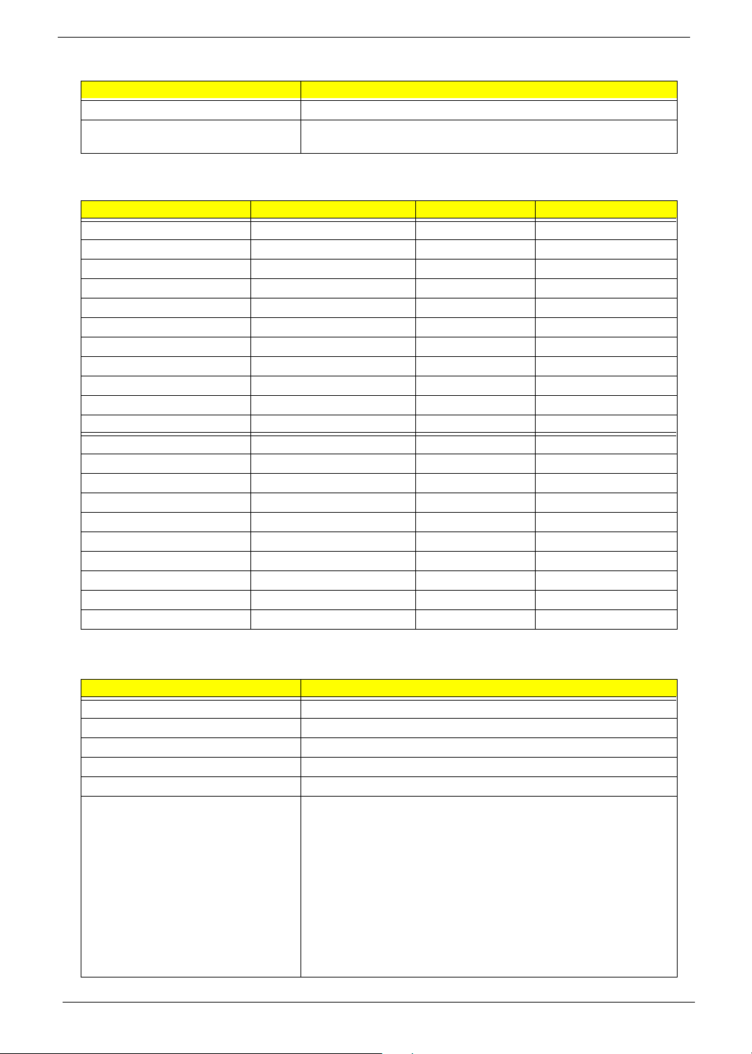
Hardware Specifications and Configurations
Processor
Item Specification
Type Pentium 4/Celeron
Socket 478
Speed 1.8G~3.06G
Minimum operating speed 0 MHz (If Stop CPU Clock in Sleep State in BIOS Setup is set to
Enabled.)
Voltage Processor voltage can be detected by the system without setting any
jumper.
BIOS
Item Specification
BIOS code programmer PhoenixBIOS
BIOS version
BIOS ROM type Flash ROM
BIOS ROM size 4MB
BIOS ROM package 32-pin PLCC package
Support protocol PCI 2.2, DMI 2.00.1, E-IDE, ACPI 1.0, ESCD 1.03, ANSI ATA 3.0,
PnP 1a, Bootable CD-ROM 1.0, ATAPI
NOTE: The BIOS can be overwritten/upgraded using the AFLASH utility.
BIOS Hotkey List
Hotkey Function Description
m
Enter BIOS Setup Utility Press while the system is booting to enter
BIOS Setup Utility.
10 Chapter 1
This section has two table lists, system memory specification and the possible combinations of memory
module.
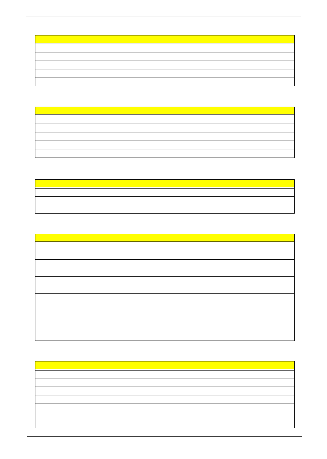
System Memory
Item Specification
Memory socket number 2 sockets (4 banks)
Support memory size per socket 128MB / 256MB/ 512MB / 1GB
Support maximum memory size 1G x2
Support memory type DDR SDRAM
Support memory speed 133MHz (PC133) (for Local Bus speed 133MHz)
Support memory voltage 2.5 V
Support memory module package 184-pin Desktop Long-DIMM
Support to parity check feature Yes
Support to Error Correction Code (ECC) feature Yes
Memory module combinations You can install memory modules in any combination as long as
they match the above specifications.
Memory Combinations
Slot Memory Module Tot al Memor y
Slot 1 128, 256, 512MB, 1G 128MB~1G
Slot 2 128, 256, 512MB, 1G 128MB~1G
Maximum System Memory Supported 128MB~2G
Cache Memory
Item Specification
First-Level Cache Configurations
Cache function control Enable/Disable by BIOS Setup
Second-Level Cache Configurations
L2 Cache RAM type PBSRAM
L2 Cache RAM size 256/512KB
L2 Cache RAM speed One-half the processor core clock frequency
L2 Cache RAM voltage
L2 Cache function control Enable/Disable by BIOS Setup
L2 Cache scheme Fixed in write-back
Video Memory
Item Specification
Memory size 64 MB
Fixed on-board or upgradeable Fixed on-board (nVIDIA) or UMA Memory (SiS M650)
This section has two table lists, the video interface specification and its supported display modes.
Video Interface
Item Specification
Video controller SiS M650 or nVIDIA NV18M
Chapter 1 11
Video Interface
Item Specification
Video controller resident bus AGP bus
Video interface support Video YUV texture in all texture formats
Display Screen Resolution Refresh Rate (Hz) Hor. Scan (KHz) Pixel Clock (MHz)
640x480 60 31.5 25.2
640x480 72 37.4 32.0
640x480 75 37.5 31.5
640x480 85 43.3 36.0
640x480 120 63.7 55.0
800x600 56 35.2 36.0
800x600 60 37.8 39.9
800x600 72 48.0 50.0
800x600 75 46.9 49.5
800x600 85 53.7 56.2
800x600 100 62.5 67.5
800x600 120 76.1 81.0
800x600 160 101.9 110.0
1024x768 70 56.5 75.0
1024x768 75 60.0 78.8
1024x768 100 79.0 110.0
1280x1024 43 50.0 80.0
1280x1024 60 64.0 110.0
1280x1024 85 91.2 157.5
1600x1200 60 76.2 156.0
1600x1200 85 106.2 229.5
H/W DVD accelerator
Audio Interface
Item Specification
Audio controller SiS962
Audio controller resident bus AC’97
Audio function control Enable/disable by OS Setup
Mono or stereo Stereo
Resolution 20 bits
Compatibility Sound Blaster Pro/16 compatible
Mixed digital and analog high performance chip
Enhanced stereo full duplex operation
High performance audio accelerator and AC’97 support
Full native DOS games compatibility
Virtual FM enhances audio experience through real-time FM-to-Wavetable
conversion
MPU-401(UART mode) interface for wavetable synthesizers and MIDI
devices
Integrated dual game port
Meets AC’97and WHQL specifications
12 Chapter 1
Audio Interface
Item Specification
Music synthesizer Yes, internal FM synthesizer
Sampling rate 48 KHz (max.)
MPU-401 UART support Yes
Microphone jack Supported
Headphone jack Supported
IDE Interface
Item Specification
IDE controller SiS962
IDE controller resident bus PCI bus
Number of IDE channel 2
Support IDE interface E-IDE (up to PIO mode-4 and Ultra DMA 33/66), ANSIS ATA rev.3.0 ATAPI
Support bootable CD-ROM Yes
Floppy disk drive Interface
Item Specification
Floppy disk drive controller SMSC LPC47M192
Floppy disk drive controller resident bus LPC interface
Support FDD format 360KB, 720KB, 1.2MB, 1.44MB, 2.88MB
Parallel Port
Item Specification
Parallel port controller SMSC LPC47M192
Parallel port controller resident bus LPC interface
Number of parallel ports 1
Support ECP/EPP SPP / Bi-directional / ECP / EPP
Connector type 25-pin D-type female connector
Parallel port function control Enable/disable by BIOS Setup
Optional ECP DMA channel
(in BIOS Setup)
Optional parallel port I/O address
(via BIOS Setup)
Optional parallel port IRQ
(via BIOS Setup)
DMA channel 1
DMA channel 3
378h
278h
IRQ5
IRQ7
Serial Port
Item Specification
Serial port controller SMSC LPC47M192
Serial port controller resident bus LPC interface
Number of serial port 1
16550 UART support Yes
Connector type 9-pin D-type female connector
Optional serial port I/O address
(via BIOS Setup)
COM1: 2F8h, 3E8h, 2E8h
Chapter 1 13
Serial Port
Item Specification
Optional serial port IRQ
(via BIOS Setup)
COM1: IRQ 3, and 4
Modem
Item Specification
Software Modem V.9.0/9.2
Modem connector type RJ11
Full duplex Yes
USB Port
Item Specification
OHCI USB 1.1/2.0
USB Class Support legacy keyboard for legacy mode
Memory Address Map
Address Size Function
000000 - 07FFFF 512KBytes Host Memory
080000 - 09FFFF 128KBytes Host/PCI Memory
0A0000 - 0BFFFF 128KBytes PCI/ISA Video Buffer Memory
0C0000 - 0CFFFF 64KBytes Video BIOS Memory
D0000 96Kbytes ISA Card BIOS & Buffer Memory
0E0000 - 0EFFFF 64Kbytes BIOS Extension Memory
Setup and Post Memory
PCI Development BIOS
0F0000 - 0FFFFF 64Kbytes System BIOS Memory
100000 - UPPER LIMIT Main Memory
UPPER LIMIT - 4GBytes PCI Memory
PCI INTx# Assignment Map
PCI INTx PCI Devices
INTA AGP
INTB 1394, Carbus
INTC AGP, Audio, Mini, Modem
INTD LAN, Mini
INTE USB 0 (1,1)
INTF USB 1 (1.1)
INTG USB 2 (1,1)
INTH USB 3 (2,0)
14 Chapter 1
I/O Address Map
Hex Range Devices
000-00F
020-021
040-043
060-060
061-061
070-071
080-08F
0A0-0A1
0C0-0DF
0F0-0FF
170-177
1F0-1F7
278-27F
2F8-2FF
378-37F
3F0-3F5
3F6-3F6
3F7-3F7
3F8-3FF
0CF8
0CFC
778-77A
DMA Controller-1
Interrupt Controller-1
System Timer
Keyboard Controller 8742
System Speaker
CMOS RAM Address and Real Time Clock
DMA Page Register
Interrupt Controller-2
DMA Controller-2
Math Co-Processor
Secondary IDE
Primary IDE
Parallel Printer Port 2
Serial Asynchronous Port 2
Parallel Printer Port 1
Floppy Disk Controller
Secondary IDE
Primary IDE
Serial Asynchronous Port 1
Configuration Address Register
Configuration Data Register
Parallel Printer Port 1
IRQ Assignment Map
IRQx System Devices Add-On-Card Devices
IRQ0 Timer N
IRQ1 Keyboard N
IRQ2 Cascade Interrupt Control N
IRQ3 Serial Alternate Reserved
IRQ4 Serial Primary Reserved
IRQ5 MPU-401(Alternate) Reserved
IRQ6 Floppy Disk Reserved
IRQ7 Parallel Port Reserved
IRQ8 Real Time Clock N
IRQ9 N Reserved
IRQ10 N Reserved
IRQ11 N Reserved
IRQ12 PS/2 Mouse Reserved
IRQ13 Math Coprocessor Exception N
IRQ14 Primary IDE Reserved
IRQ15 Secondary IDE Reserved
NOTE: N - Not be used
Chapter 1 15
APIC mode
PCI x System Devices Add-On-Card Devices
PCI 16 VGA
PCI 17 1394, Carbus
PCI 18 Modem, WLAN (Mini PCI), Audio
PCI 19 LAN
PCI 20 USB 0 (1,1)
PCI 21 USB 1 (1,1)
PCI 22 USB 2 (1,1)
PCI 23 USB 3 (2,0)
DRQ Assignment Map
DRQx System Devices Add-On-Card Devices
DRQ0 N Reserved
DRQ1 LPT (ECP mode) Reserved
DRQ2 FDD N
DRQ3 N Reserved
DRQ4 Cascade N
DRQ5 N Reserved
DRQ6 N Reserved
DRQ7 N Reserved
NOTE: N - Not be used
Main Board Major Chips
Item Controller
System core logic SiS650 / SiS962
Video controller SiS650
Super I/O controller SiS962
Audio controller SiS650
LAN controller SiS650
HDD controller Built in SiS650
Keyboard controller Built in SiS650
RTC Built in SiS650
Environmental Requirements
Item Specifications
Temperature
Operating +10 ~ +35°C
Non-operating -20 ~ +60°C (Storage package)
Humidity
Operating 20% to 80% RH
Non-operating 20% to 80% RH
Vibration
Operating (unpacked) 5 ~ 16 Hz: 0.015 mm
16 ~ 250 Hz: 0.21 G
16 Chapter 1

Environmental Requirements
Item Specifications
Non-operating (packed) 5 ~ 27.1 Hz: 0.6 G
27.1 ~ 50 Hz: 0.016 mm
50 ~ 500 Hz: 2 G
Mechanical Specifications
Item Specification
Weight
One 3 ½ FDD and one 3.5 HDD
(without packing)
Dimensions
(main footprint)
Varied by local configuration
N/A
Chapter 1 17

Power Management Function (ACPI support function)
Device Standby Mode
T Independent power management timer for hard disk drive devices
(0-15 minutes, time step=1 minute).
T Hard disk drive goes into Standby mode (for ATA standard interface).
T Disable V-sync to control the VESA DPMS monitor.
T Resume method: device activated (Keyboard for DOS, keyboard & mouse for Windows).
T Resume recovery time: 3-5 sec.
Global Standby Mode
T Global power management timer (2-120 minutes, time step=10 minute).
T Hard disk drive goes into Standby mode (for ATA standard interface).
T Disable H-sync and V-sync signals to control the VESA DPMS monitor.
T Resume method: Return to original state by pushing external switch button, modem ring in,
keyboard and mouse for APM mode.
T Resume recovery time: 7-10 sec.
Suspend Mode
T Independent power management timer (2-120 minutes, time step=10 minutes) or pushing external
switch button.
T CPU goes into SMM.
T CPU asserts STPCLK# and goes into the Stop Grant State.
T LED on the panel turns amber colour.
T Hard disk drive goes into SLEEP mode (for ATA standard interface).
T Disable H-sync and V-sync signals to control the VESA DPMS monitor.
T Ultra I/O and VGA chip go into power saving mode.
T Resume method: Return to original state by pushing external switch button, modem ring in,
keyboard and mouse for APM mode.
T Return to original state by pushing external switch button, modem ring in and USB keyboard for
ACPI mode.
ACPI
T ACPI specification 1.0.
T S0, S1, S3 and S5 sleep state support.
T On board device power management support.
T On board device configuration support.
18 Chapter 1
s
t
System Utilities
BIOS Setup Utility
The BIOS Setup Utility is a hardware configuration program built into your computer’s BIOS (Basic Input/
Output System).
Your computer is already properly configured and optimized, and you do not need to run this utility. However, if
you encounter configuration problems, you may need to run Setup. Please also refer to Chapter 4
Troubleshooting when problem arises.
Chapter 2
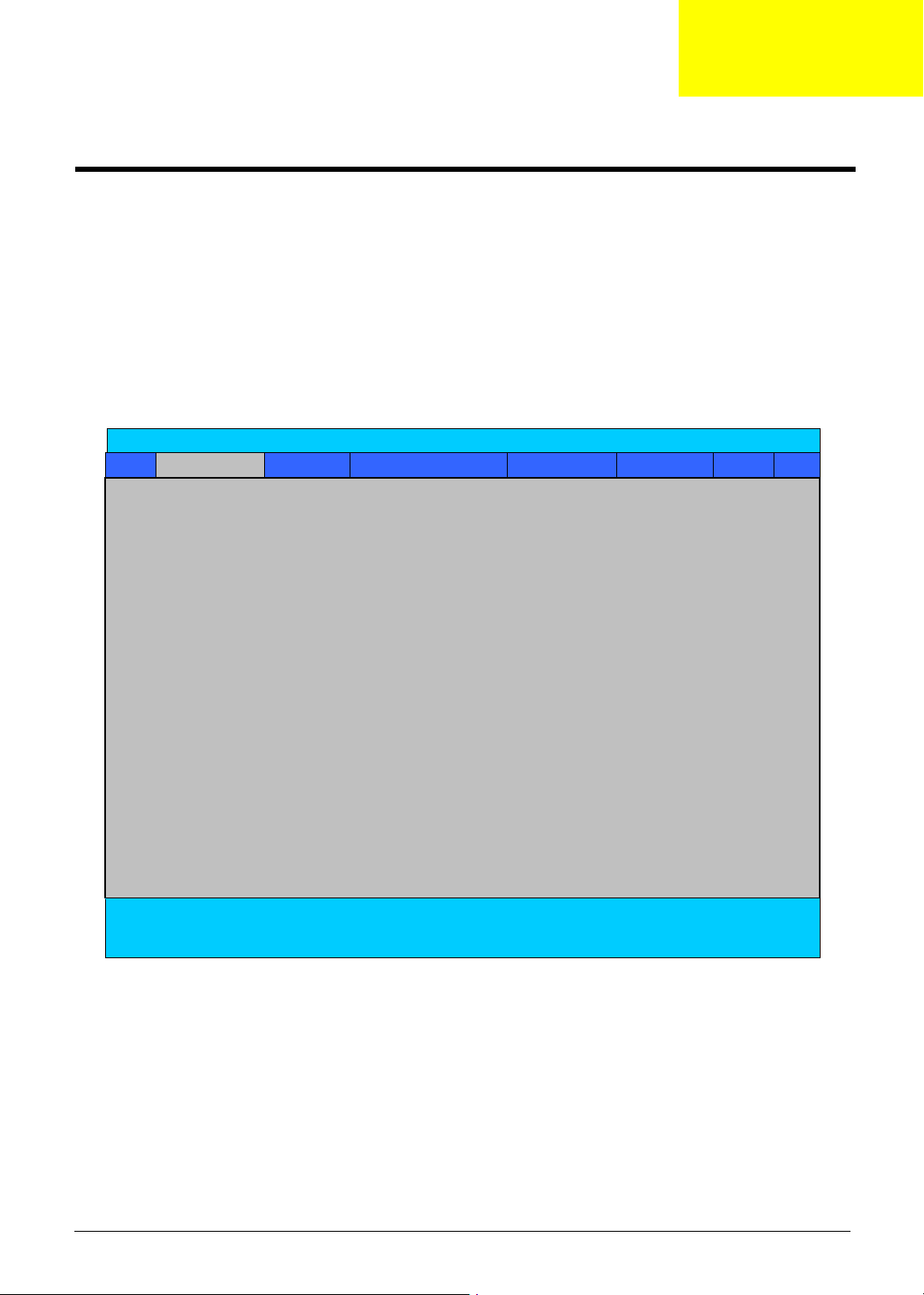
To activate the BIOS Utility, press
on the bottom of screen).
Press m to enter setup; press <C> to boot from CD-ROM; press <F12> to change boot device.
m during POST (when “Press <F2> to enter Setup” message is prompted
PhoenixBIOS Setup Utility
Info. Main System Device
Security Boot Exi
CPU Type: Intel Pentium(R) 4 CPU 2.66GHz
CPU Speed: 2660MHz
HDD1 Model Name:
HDD1 Serial Number:
ATAPI Device:
System BIOS Ver: A3Axx
VGA BIOS Ver:
KBC Ver: x.x
Serial Num: xxxxxxxxxxxxxxxxxxxxxx
Asset Tag Number:
Product Name: Aspire 1700
Manufacture Name: acer
UUID: xxxxxxxxxxxxxxxxxxxxxxxxxxxxxxxx
F1 Help ↑↓ Select Item F5/F6 Change Values F9 Setup Defaults
Esc Exit ←→ Select Menu Enter Select 4Sub-Menu F10 Save and Exit
Chapter 2 19

Navigating the BIOS Utility
There are six menu options: Info., Main, System Devices, Security, Boot, and Exit.
Follow these instructions:
T To choose a menu, use the cursor left/right keys (zx).
T To choose a parameter, use the cursor up/down keys ( wy).
T To change the value of a parameter, press por q.
T A plus sign (+) indicates the item has sub-items. Press e to expand this item.
T Press ^ while you are in any of the menu options to go to the Exit menu.
T In any menu, you can load default settings by pressing t. You can also press u to save any
changes made and exit the BIOS Setup Utility.
NOTE: You can change the value of a parameter if it is enclosed in square brackets. Navigation keys for a
particular menu are shown on the bottom of the screen. Help for parameters are found in the Item
Specific Help part of the screen. Read this carefully when making changes to parameter values.
This menu provides you the information of the system.
20 Chapter 2
 Loading...