

Page 1

ALW-3016
Acer Switch
16-port 10/100Mbps Switch
User's Guide
Page 2

Copyright
Copyright©1998-1999 Acer Netxus Inc. All rights reserved. No part of this
publication may be reproduced, transmitted, transcribed, stored in a
retrieval system, or translated into any language or computer language, in
any form or by any means, electronic, mechanical, magnetic, optical,
chemical, manual or otherwise, without the prior written permission of Acer
Netxus Inc.
Disclaimer
Acer Netxus Inc. makes no representations or warranties, either expressed
or implied, with respect to the contents hereof and specifically disclaims
any warranties, merchantability or fitness for any particular purpose. Any
software described in this manual is sold or licensed “as is”. Should the
programs prove defective following their purchase, the buyer (and not this
company, its distributor, or its dealer) assumes the entire cost of all
necessary servicing, repair, and any incidental or consequential damages
resulting from any defect in the software. Furthermore, Acer Netxus Inc.
reserves the right to revise this publication and to make changes from time
to time in the contents hereof without obligation to notify any person of
such revision or changes.
Other brand and product names are trademarks and/or registered trademarks of
their respective holders.
User's Manual
I
Page 3

Table of Contents
Chapter 1 Overview
1.1 Product goal.......................................................................1
1.2 Product configuration.........................................................1
Chapter 2 Make your Switch ready
2.1 Installing the switch............................................................2
2.2 Connecting to the power supply.........................................3
2.3 Rack mounting...................................................................4
2.4 Connecting to computers...................................................5
2.5 LEDs interface overview.....................................................5
Chapter 3 Apply a feasible networking
3.1 Connecting a hub/switch to normal port.............................7
3.2 How to use uplink port........................................................8
3.3 Application..........................................................................8
Chapter4 Trouble shooting................................................9
Appendix: Specification.......................................................10
II
User's Manual
Page 4
1. Overview
Thanks for your purchase of the AcerSwitch 3016. AcerSwitch is an 16port dual speed switch works as backbone switch in SOHO environment
for connecting the server or heavy-load user or hubs in LAN environment.
1.1 Product goal
AcerSwitch ALW-3016 provides high-speed and easy access to the LAN
and Intranet for corporations. It allows data transmission at speeds of 10
Mbps or 100 Mbps. It provides an easy installation, all you have to do is
plug the cables from the adapter cards or hub port to the ports, check the
LEDs and you can start networking. And AcerSwitch also provides some
advanced features only provided in some corporate products such as FAN
error. Advise you in advance to prevent the down of LAN or damage of the
equipment.
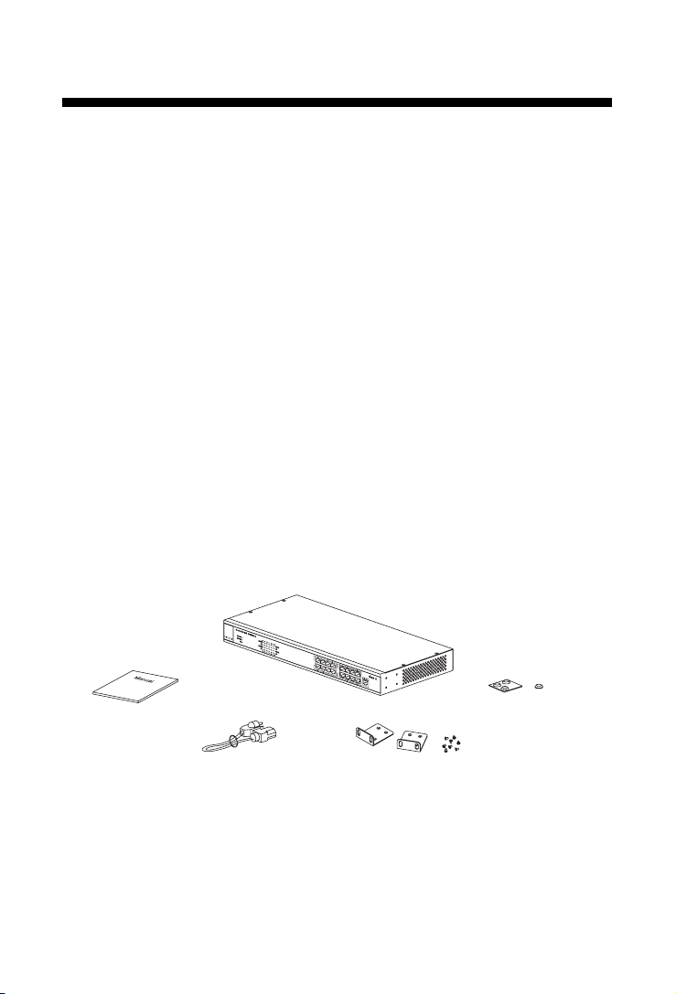
1.2 Product configuration
The product configuration inside the package is shown in the figure 1-2-1.
Please check the contents of the package if there is any missing part
before using the switch. The accessories of this product include:
1. ALW-3016 dual speed switch
2. User Manual
User's Manual
5. Rubber Footpads
3. Power Code
Figure 1-2-1 Product configuration of ALW-3016
4. Mounting Brackets and Screws
1
Page 5
2. Make Your Switch Ready
This chapter will guide you through how to install the AcerSwitch ALW-
3016. It includes procedures for connecting to the external power supply,
installing the switch on your working surface, connecting the switch to your
computer, and guidelines to see if it works well. Before setting up your
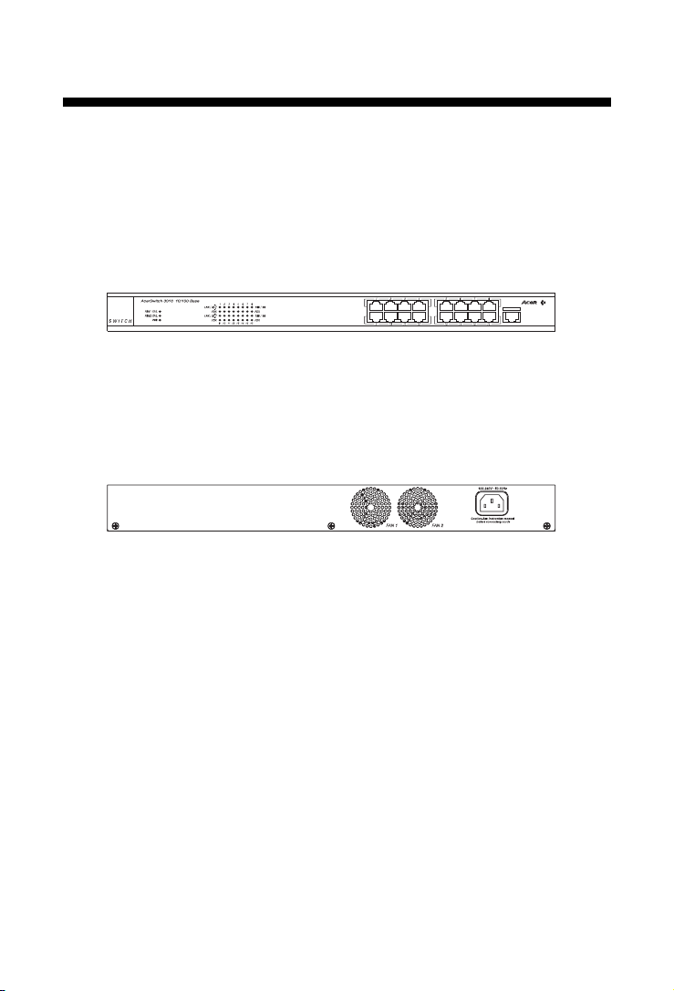
switch, please take notes of the front and rear panel of this switch, as
shown in Figure 2-1 and 2-2.
Figure 2-1 Front panel
Figure 2-2 Rear Panel
2.1 Installing the switch
You have to find a solid working surface to place the switch and make sure
the equipment is not close to any high voltage power source or overheated sources. Also keep away from electronic equipment sensitive to
electronic interface. The brief procedures of installing your switch should be:
2
User's Manual
Page 6

2.2 Connecting to the power supply
Carefully unpack the AcerSwitch ALW-3016 and it's accessories. For the
first time that you use this switch, please make sure there is all the same
as the checking list in the package. The procedure for connecting to the
power will be:
1. Place the switch on the desktop and remove the packing box of the
power adapter.
2. Please stretch and plug the cord into the power jack of the switch.
3. Check if the PWR LED lights up. If it lights up, then the switch is ready
to be connected to the network. See Figure 2-2-1.
Figure 2-2-1 Connecting to the power
User's Manual
3
Page 7

2.3 Rack mounting
To install the ALW-3016 switch in a 19-inch rack, please follow these steps:
1. If the switch has rubber footpads on the bottom of the unit, please
remove them.
2. Locate the rack mounting holes on both sides of the switch (see Figure
2- 3).
3. Using a cross-head screwdriver, attach the two mounting brackets to
both sides of the switch with the four screws supplied with the unit (see
Figure 2- 3).
4. Place the switch in the rack and align the holes in the mounting bracket
with the holes in the rack chassis (see Figure 2- 4).
5. Insert two mounting screws (the rack-mount equipment should provide
these screws), into each of the mounting brackets and tighten with a
suitable screwdriver.
Figure 2-3: Attaching mounting brackets (8 screws: M3x5)
Figure 2-4: Attaching mounting brackets for a rack mount (4 screws: M5x10)
Note: The pannel wall should be able to bear three times of the system's
weight
4
User's Manual
Page 8

2.4 Connecting to computers
Make sure the switch is ready for networking by checking if the PWR
indicator displays.
1. Shut down the computer and install an adapter card in.
2.
Plug in the one end of UTP cables to the RJ-45 phone jack of adapter.
3. Plug the other end of UTP to normal ports of the switch.
4.
Turn on the PC and check if the Link LEDs on the adapter card and the
switch (Named as LNK ACT 100/LNK ACT 10) are lit up. See Figure 2-4-1
If the LED is not lit up, there must be something wrong and please
reference to Chapter 4 for quick trouble shooting.
Figure 2-4-1 Connecting to computers
2.5 LEDs interface overview
You can observe the LEDs status to see if the hub works fine. The
meanings of LEDs are summarized as Table 2-5-1.
User's Manual
5
Page 9

Table 2-5-1 LEDs definition
2.5.1 System indicators
PWR: When the power is connected rightly, the PWR LED will be lit on
Green. If the LED is not lit on, then you should check the connection of
your power and the outlet of power.
Fan Err.: When the fan malfunction at work, then the Fan Err LED will be
lit up and blink. And when the fan is fail, the LED will be lit without blinking.
You should check you fan and your vender and have a new fan to instead
of the old one to make sure the equipment will work normally.
Note: There are two Fan inside the ALW-3016. Fan Err1 & Fan Err2 indicate the two
Fans individually.
2.5.2 Port indicators
LNK ACT 100/LNK ACT 10: When the port is linked with 100Mbps device,
the LNK ACT 100/LNK ACT 10 will be lit on GREEN, or it will be lit on
orange with 10Mbps device.And when there's any transmission activity in
the port, the LED will be blinking in GREEN with 100Mbps or in orange
with 10Mbps. If the port is linked, and the LED isn't lit up, please check if
the port connector fasten tightly.
FDX: When the port is connected with full duplex, it will be lit up on
GREEN. Others it will be DARK.
6
User's Manual
Page 10

3. Apply a feasible networking
This chapter describes the network topology for hybrid 10 Mbps and 100
Mbps networks, cabling requirement for connections, the interoperability
between hubs and switches. And tell you how to use the ALW-3016 to
expand your port numbers.
3.1 Connecting a hub/switch to normal port
You can use the ALW-3016 as a backbone switch in small and medium
size LAN environment, and for the purpose of expanding your port number
you can connect another hub/switch with it's uplink port to the normal port
of ALW-3016. See Figure 3-1-1
1. Place the hub/switch on a stable surface.
2. Use one end of the UTP/STP cord to connect to the uplink port of the
hub/switch.
3. Use the other end of the UTP/STP cord to connect to the normal port of
ALW-3016
4. Check the status of LNK ACT 100/LNK ACT 10 LED. If the LNK ACT
100 /LNK ACT 10 LED is lit on green then it works normal.
5. Then you can connect the terminal to the new hub/switch
ALW-3016
ALH-324D
Figure 3-1-1 Connecting to normal port with other hub/switch
User's Manual
7
Page 11

3.2 How to use up-link port
With up-link port you can use it to cascade to another switch to expand
your network. Please refer to the following procedure.
1. Use one end of UTP/STP to connect to the up-link port of ALW-3016
2. Use the other end to connect to the normal port of the new switch
3.
Make sure the LNK ACT 100/LNK ACT10 LED is lit then it will work
normally.(See Figure 3-2-1)
ALW-3024
ALW-3016
Figure 3-2-1 Up-link port connection
3.3 Application
With this application diagram, you can clearly see the possibility what
ALW-3016 can do for you in expand your network. (See Figure 3-3-1)
Figure 3-3-1 Application diagram
Notice: Use UTP Cat. 5 to connect to 100 Mbps equipment and UTP Cat.
3,4,5 to connect to 10 Mbps one.
8
User's Manual
Page 12

4. Trouble shooting
Symptoms Possible Reason Suggestion
All LEDs are off. The hub is not receiving 1. Check if the power adapter
DC power. plug is securely fastened into the
AC outlet.
2. Contact you vender if still
unworkable.
Fan Err. LED is The fan is dead or work 1. Check your fan, maybe you
blinking or down abnormal should have a new fan.
2. Contact the vender
LNK LED of a 1.The UTP cable is not 1. Check the cable connection
connected port securely connected
is off. 2.The port is bad 2. Try to connect another port
3.If the other party is a PC, 3. Check if the network interface
the Network Interface card (NIC) were installed
Card (NIC) could be not properly.
working
4.If the other party is 4. Make sure ALW -3016 normal
a hub or LAN switch, port is connected to the other
the connected ports signal hub's (or switch's) uplink port,
could be cross-over and ALW -3016 uplink port is
connected the other's normal port.
5.The UTP cable is broken, 5. Try another normal cable.
or it is cross-overed cable.
100 LED is not lit The auto-negotiation 1. Check if you force the connection
when connected function is failed between equipment in specific mode.
to a 100 NIC or ALW-3016 and the other If, yes, then free it to auto-negotiation
100Hub (but LNK part 2. Un-plug the UTP cable from
LED is lit.) ALW -3016 and plug-in again.
3. Check if the NIC is setted to
auto-negotiation mode.
4. Check if the other hub is set
to auto-negotiation mode
5. If the above steps does not
work, it is an interoperability
problem, contact your vender.
User's Manual
9
Page 13

Appendix: Specifications
Physical Specification
Ports 16 dual-speed 10 BASE-T/100 BASE-TX RJ-45 ports
1 Up-Link 10 Base-T/100 Base-TX RJ-45 ports
Dimension 440 (Width) x 205(Depth) x 45.2mm(Height)
Weight 2.5 Kg
Power Switching power supply
Input: 100~120/220~240V AC, 50-60Hz
LEDs indicator
Power, fan error, LNK/ACT, FDX for each port and Speed 10/100Mbps
Switch Processing Scheme
Store-and-forward
Address Table supports up to 8K unicast addresses
Cabling requirement
UTP Cat. 3,4,5 for 10Base-T
UTP Cat. 5 for 100 Base-TX
Standards Conformance
Standards IEEE 802.3/802.3u
Environmental
Operating temperature: 0~50˚C (32~122˚F)
Operating humidity: 20%~80% non-condensing
EMI FCC Class A, CE Class A, VCCI Class 1 and C-Tick
class A
10
User's Manual
Page 14

Product Limited Warranty
Acer Netxus Incorporated (ANI) warrants its product to be free from defects in
materials and workmanship, under normal use and service, for the following lengths of
time from the date of purchase from ANI or its Authorized Resellers.
Network adapter card Limited Lifetime
Unmanaged hub *Limited Lifetime
Dual-speed hub *3 year
Switch and managed hub *3 year
* Power supply/adapter and fans in these devices provide ONE YEAR warranty
All products with limited lifetime warranty have a standard five-year warranty. This
warranty does not cover the product if it is damaged by abuse, accident, misuse,
improper installation, or improper testing. If a product does not operate as warranted
during the applicable warranty period, ANI shall, at its option and expense, either repair
the defective product or part returned to ANI, or deliver to customer an equivalent
product or part to replace the defective item. Definitely, all products that are replaced
will become the property of ANI. Replacement products may be new or reconditioned.
Any replacement or repaired product or part has a ninety days warranty or the
remainder of the initial warranty period, whichever is longer. ANI shall not be
responsible for any software, firmware, information, or memory data of customer
contained in, stored on, or integrated with any products returned to ANI pursuant to any
warranty. Before you obtain warranty service, you must request an RMA (Return
Materials Authorization) number by calling, faxing or writing ANI’s Customer Service
Department at the numbers listed below. You must use the original container (or the
equivalent) and pay the shipping charge.
ANI SHALL NOT BE HELD LIABLE FOR INCIDENTAL, CONSEQUENTIAL, INDIRECT,
SPECIAL OR RUNTIME DAMAGES OF ANY KIND; OR FOR LOSS OF REVENUE,
LOSS OF BUSINESS, OR OTHER FINANCIAL LOSS ARISING OUT OF OR IN
CONNECTION WITH THE SALE, INSTALLATION, MAINTENANCE, USE,
PERFORMANCE, FAILURE, OR INTERRUPTION OF ITS PRODUCTS, EVEN IF ANI
OR ITS AUTHORIZED DEALER HAS BEEN ADVISED OF THE POSSIBILITY OF
SUCH DAMAGES.
If you purchased this product in the UNITED STATES, some states do not allow the
limitation or exclusion of liability for incidental consequential damages, so the above
limitation may not apply to you.
( Authorized distributors' or Resellers' Stamp )
Model Name
Series No. (S/N)
Purchase Date
/ /
Page 15

Contact us:
Acer Computer International Ltd.
Taiwan Branch
Tel: 886-2-2696 0123 ext.3130
Fax: 886-2-8691 2316
http://www.aci.acer.com.tw
Acer America Corporation
Tel: 1-408-432 6200
Fax:1-408-922 2993
http://www.acer.com/aac
Distribution/Information
Hotline: 1-800-369 6736
Fax: 1-408-432 0496
http://www.acer.com/aac/aod
Acer Latin America Inc.
Tel: 1-305-392 7200
Fax:1-305-392 7216
Acer Japan Corporation
Tel: 81-4-8290 1819
Fax: 81-4-8290 1820
Acer Computer B.V.
Tel: 31-73-645 9645
Fax: 31-73-645 9599
Acer UK Limited
Tel: 44-1628-533422
Fax: 44-1628-524071
http://www.aceruk.co.uk
Acer Computer France S.A.R.L.
Tel: 33-1-4817 4040
Fax: 33-1-4817 4089
Acer Computer GmbH
Tel: 49-4102-488-0
Fax: 49-4102-488-101
Dealers' Information
Hotline: Germany 0180-3234781
End users' Information
Hotline: Germany 0180-5009898
Acer Computer Iberica, S.A.
Tel: 34-3-499-0303
Fax: 34-3-499-0483
Acer Italy/Texas Instruments
Tel: 39-2-2692-2565
Fax: 39-2-2692-1021
Page 16

100% Recyclable Paper
P/N: 49.23020.001
Acer Netxus Inc.
A Communications Company of Acer
 Loading...