

Page 1

Altos R700 Series
User’s guide
Page 2

Copyright © 2002 Acer Incorporated
All Rights Reserved.
Altos R700 Server Board
User’s guide
Original issue: December 2002
Changes may be made periodically to the information in this publication without obligation
to notify any person of such revision or changes. Such changes will be incorporated in new
editions of this manual or supplementary documents and publications. This company makes
no representations or warranties, either expressed or implied, with respect to the contents
hereof and specifically disclaims the implied warranties of merchantability or fitness for a
particular purpose.
Record the model number, serial number, purchase date, and place of purchase information in
the space provided below. The serial number and model number are recorded on the label
affixed to your computer. All correspondense concerning your unit should include the serial
number, model number, and purchase information.
No part of this publication may be reproduced, stored in a retrieval system, or transmitted, in
any form or by any means, electronic, mechanical, photocopy, recording, or otherwise,
without the prior written permission of Acer Incorporated.
Model Number : _________________________________
Serial Number: ___________________________________
Purchase Date: ___________________________________
Place of Purchase: ________________________________
Acer and the Acer logo are registered trademarks of Acer Inc. Other company’s product
names or trademarks are used herein for identification purposes only and belong to their
respective companies.
Page 3

iii
Notices
FCC notice
Class A devices do not have an FCC logo or FCC IDE on the label. Class B devices
have an FCC logo or FCC IDE on the label. Once the class of the device is
determined, refer to the following corresponding statement.
Class A equipment
This device has been tested and found to comply with the limits for a Class A
digital device pursuant to Part 15 of the FCC Rules. These limits are designed to
provide reasonable protection against harmful interference when the
equipment is operated in a commercial environment. This equipment
generates, uses, and can radiate radio frequency energy, and if not installed
and used in accordance with the instructions, may cause harmful interference to
radio communications. Operation of this equipment in a residential area is
likely to cause harmful interference, in which case the user will be required to
correct the interference at personal expense.
Class B equipment
This device has been tested and found to comply with the limits for a Class B
digital device pursuant to Part 15 of the FCC Rules. These limits are designed to
provide reasonable protection against harmful interference in a residential
installation. This device generates, uses, and can radiate radio frequency
energy, and if not installed and used in accordance with the instructions, may
cause harmful interference to radio communications.
However, there is no guarantee that interference will not occur in a particular
installation. If this device does cause harmful interference to radio or television
reception, which can be determined by turning the device off and on, the user
is encouraged to try to correct the interference by one or more of the following
measures:
• Reorient or relocate the receiving antenna
• Increase the separation between the device and receiver
• Connect the device into an outlet on a circuit different from that to which
the receiver is connected
• Consult the dealer or an experienced radio/television technician for help
Page 4

iv
Notice: Shield cables
All connections to other computing devices must be made using shielded cables
to maintain compliance with FCC regulations.
Notice: Peripheral devices
Only peripherals (input/output devices, terminals, printers, etc.) certified to
comply with the Class A or Class B limits may be attached to this equipment.
Operation with noncertified peripherals is likely to result in interference to
radio and TV reception.
Caution! Changes or modifications not expressly approved by
the manufacturer could void the user’s authority, which is granted
by the Federal Communications Commission, to operate this
server.
Use conditions
This part complies with Part 15 of the FCC Rules. Operation is subject to the
following two conditions: (1) this device may not cause harmful interference,
and (2) this device must accept any interference received, including interference
that may cause undesired operation.
Notice: Canadian users
This Class A/Class B digital apparatus meets all requirements of the Canadian
Interference-Causing Equipment Regulations.
Page 5

Important safety instructions
Read these instructions carefully. Save these instructions for future reference.
1 Follow all warnings and instructions marked on the product.
2 Unplug this product from the wall outlet before cleaning. Do not use
liquid cleaners or aerosol cleaners. Use a damp cloth for cleaning.
3 Do not use this product near water.
4 Do not place this product on an unstable cart, stand, or table. The product
may fall, causing serious damage to the product.
5 Slots and openings on the back or bottom side of the chassis are provided
for ventilation; to ensure reliable operation of the product and to protect
it from overheating, these openings must not be blocked or covered. The
openings should never be blocked by placing the product on a bed, sofa,
rug, or other similar surface. This product should never be placed near or
over a radiator or heat register, or in a built-in installation unless proper
ventilation is provided.
6 This product should be operated from the type of power indicated on the
marking label. If you are not sure of the type of power available, consult
your dealer or local power company.
7 Do not allow anything to rest on the power cord. Do not locate this
product where persons will walk on the cord.
8 If an extension cord is used with this product, make sure that the total
ampere rating of the equipment plugged into the extension cord does not
exceed the extension cord ampere rating. Also, make sure that the total
rating of all products plugged into the wall outlet does not exceed the fuse
rating.
9 Never push objects of any kind into this product through chassis slots as
they may touch dangerous voltage points or short out parts that could
result in a fire or electric shock. Never spill liquid of any kind on the
product.
10 Do not attempt to service this product yourself, as opening or removing
covers may expose you to dangerous voltage points or other risks. Refer all
servicing to qualified service personnel.
11 Unplug this product from the wall outlet and refer servicing to qualified
service personnel under the following conditions:
a When the power cord or plug is damaged or frayed
b If liquid has been spilled into the product
c If the product has been exposed to rain or water
v
Page 6

vi
d If the product does not operate normally when the operating
instructions are followed. Adjust only those controls that are covered
by the operating instructions since improper adjustment of other
controls may result in damage and will often require extensive work
by a qualified technician to restore the product to normal condition.
e If the product has been dropped or the cabinet has been damaged
f If the product exhibits a distinct change in performance, indicating a
need for service.
12 Replace the battery with the same type as the product's battery we
recommend. Use of another battery may present a risk of fire or explosion.
Refer battery replacement to a qualified service technician.
13 Warning! Batteries may explode if not handled properly. Do not
disassemble or dispose of them in fire. Keep them away from children and
dispose of used batteries promptly.
14 Use only the proper type of power supply cord set (provided in your
accessories box) for this unit. It should be a detachable type: UL listed/CSA
certified, type SPT-2, rated 7A 125V minimum, VDE approved or its
equivalent. Maximum length is 15 feet (4.6 meters).
Page 7

Notices iii
FCC notice iii
Important safety instructions v
1 Description 1
Server Board Features 2
Server Board Connector and
Component Locations 3
Back Panel Connectors 5
Processor 7
Memory 8
PCI Riser Slots 9
Video 10
SCSI Controller 11
Network Controller 12
NIC Connector and Status LEDs 12
System Cooling 13
Keyboard and Mouse 14
RJ-45 Serial Port 15
ACPI 17
System Management 18
Baseboard Management Controller 18
Field Replaceable Units and Sensor Data Records 18
System Event Log 19
Platform Event Management 19
Emergency Management Port 20
Acer Advance Server Management (ASMe) 21
Security 22
Intrusion Switch Monitoring 22
Software Locks 22
Using Passwords 22
Secure Mode 23
Summary of Software
Security Features 24
vii
2 Installation Procedures 27
Rearrange the Standoffs 28
Install the Server Board 29
Install the Processor Retention Brackets 30
Installing Processors 31
Memory 34
Connect Cables 35
Installing a Service Partition on the Server (Optional) 36
Page 8

viii
Installing your Operating System 36
Installing Acer Advance Server Management 36
3 Upgrading 39
Tools and Supplies Needed 40
Cautions 41
Replacing the Back up Battery 43
4 Configuration Software and Utilities 45
Service Partition (Optional) 47
Configuration Utilities 48
System Software Update Sequence 48
Hot Keys 50
Power-On Self-Test (POST) 51
BIOS Setup 52
If BIOS Setup Is Inaccessible 52
Temporarily Changing the Boot Device Priority 52
Running the Adaptec SCSISelect Utility 54
When to Run the Adaptec SCSISelect Utility 54
Running the SCSISelect Utility 54
Configuring the Adaptec SCSI Adapter 55
Direct Platform Control (DPC) Console 57
DPC Console Modes of Operation 57
Running the DPC Console 58
Using the System Setup Utility 59
Creating SSU Diskettes 59
Running the SSU 60
Setting Boot Device Priority 62
Setting Passwords and Security Options 62
Viewing the System Event Log 63
Viewing FRU Information 64
Viewing Sensor Data Records 65
Updating System Firmware and BIOS 65
Saving and Restoring the System Configuration 67
Alerting for Platform Events 68
Managing the Server Remotely 71
Software Updates 74
Creating a Bootable Diskette 74
Software Update Package 74
Recovering the BIOS 75
Firmware Update Utility Description 76
Running the Firmware Update Utility 76
FRU/SDR Load Utility Description 76
Page 9

5 Solving Problems 81
Resetting the System 82
Initial System Startup 83
Checklist 83
Running New Application Software 85
Checklist 85
After the System Has Been
Running Correctly 86
Checklist 86
More Problem Solving Procedures 87
Monitoring POST 87
Verifying Proper Operation of Key System Lights 87
Confirming Loading of the Operating System 88
Specific Problems and
Corrective Actions 89
Power Light Does Not Light 89
No Characters Appear on Screen 89
Characters Are Distorted or Incorrect 90
System Cooling Fans Do Not Rotate Properly 90
Diskette Drive Activity Light Does Not Light 91
CD-ROM Drive Activity Light Does Not Light 91
Problems with Application Software 92
Bootable CD-ROM Is Not Detected 92
Problems with Network 93
ix
6 Technical Reference 95
Server Board Jumpers 97
Diagnostic LEDs 99
POST Error Codes and Messages 108
BIOS Recovery Beep Codes 112
Bootblock Error Beep Codes 113
Appendix A: Equipment Log and
Power Consumption Worksheets 115
Equipment Log 116
Current Usage 118
Calculating Power Usage 118
Worksheet, Calculating DC Power Usage 118
Worksheet, Total Combined Power
Used by the System 120
Page 10

x
Page 11

1 Description
Page 12

2
1 Description
Server Board Features
Table 1 Server Board Features
Feature Description
Processors Dual processor slots supporting Intel® Xeon™ processors
in an INT3/FCPGA Socket 604 package.
Memory Six dual inline memory module (DIMM) slots support:
• DDR-200 or DDR-266
168-pin, DIMMs
• From 256MB to 12 GB of memory
Graphics Integrated onboard ATI RAGE† XL PCI SVGA controller.
Video Memory 8 MB SDRAM of video memory.
PCI bus Two PCI riser slots capable of supporting either of the
following configurations:
• 1U configuration-one full-length, full-height 64-bit PCI
riser slot and one Low Profile (LP) 64-bit PCI riser slot.
• 2U configuration-three full-length, full-height 64-bit PCI
riser slots and three LP 64-bit PCI riser slots.
1
compliant, ECC, registered, 72-bit,
Network Dual on-board 10/100/1000 Network Interface Controllers
(NIC).
System I/O
(see Table 1)
Form Factor Server ATX form factor.
N lеду=aaoJOSS=бл=лмййзкнЙЗ=пбнЬ=RPPjeт=cкзен=pбЗЙ=_мл=Ecp_FK
aaoJOMM=зк=aaoJOSS=~кЙ=ДзнЬ=лмййзкнЙЗ=пбнЬ=QMMjeт=cp_K
One PS/2† keyboard/mouse port (6 pin DIN).
One VGA video port (15 pin).
Two external USB ports, internal header providing two
additional USB.
One external serial port (RJ-45), one internal COM 1
header.
One external SCSI port (SCSI server board only), one
internal.
Two NIC ports (RJ-45).
Page 13
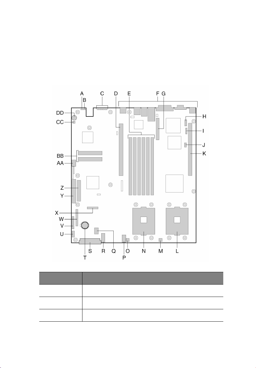
Server Board Connector and Component Locations
The Altos R700 Server Board comes only in SCSI version. Figure 1 is a
view of SCSI versions.
3
Label Description
A System status LED
B ID LED
C Diagnostic LEDs (POST code)
Page 14

4
Label Description
D 64-bit PCI riser slot for PCI-X bus B (full height)
EDIMM slots
F I/O ports
G SCSI channel B connector (SCSI version only)
H COM 1 serial header
I ICMB connector
J IPMB connector
K 64-bit PCI riser slot for PCI-X bus C (low profile)
L Secondary processor socket
M Secondary processor fan connector
N Primary processor socket
O Primary processor fan connector
1 Description
P Auxiliary signal connector
Q Sys fan 1 connector
R Sys fan 2 connector
S Main power connector
T Battery
U Power supply signal connector
V ATX front panel connector
W SSI front panel connector
X Floppy/FP/IDE connector
Y ATA/IDE connector
Z Floppy drive connector
Page 15
Label Description
AA USB 2 & 3 header
BB ATA-100 connectors (ATA version only)
CC Hard Disk Drive LED header
DD Speaker
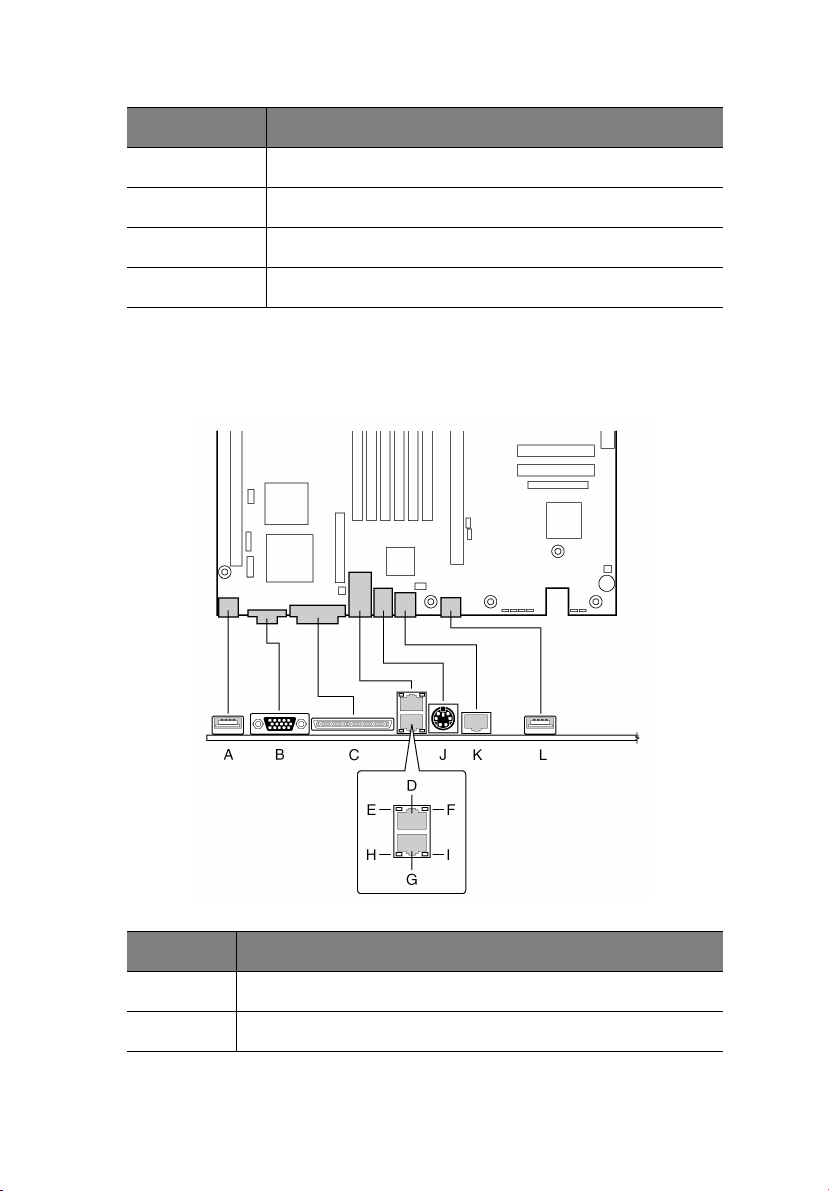
Back Panel Connectors
5
Label Description
A USB 0 connector
B Video connector
Page 16

6
Label Description
C SCSI channel A connector (SCSI server board only)
D NIC 2 RJ-45 connector
E Status LED
F Speed LED
G NIC 1 RJ-45 connector
H Status LED
I Speed LED
J PS/2 keyboard/mouse connector
K RJ-45 serial port
L USB 1 connector
1 Description
Page 17

Processor
The Altos R700 server board accommodates one or two Intel Xeon
processors with 512k cache in the INT3/FCPGA Socket 604 package. This
processor uses the .13 micron technology.
7
Page 18

8
1 Description
Memory
The system board has six 168-pin DIMM slots each supporting 72-bit
ECC registered DDR DIMMs (DDR-200 or DDR-266 compatible). Memory
is partitioned in three banks. You may install a minimum of 256 MB
(128MB x 2) and as much as 12 GB. Memory must be installed in pairs,
starting with bank 1 (slots 1B and 1A).
The controller automatically detects, sizes, and initializes the memory
array, depending on the type, size, and speed of the installed DIMMs,
and reports memory size and allocation to the server via configuration
registers.
Note: Use DIMMs that have been tested for compatibility with the
server board. Contact your sales representative or dealer for a
current list of approved memory modules.
Page 19

PCI Riser Slots
The server board has two PCI riser slots. Riser slot B provides the
following features:
• 184 pin, 5 volt keyed, 64-bit expansion slot connector
• Support for either a 1-slot or a 3-slot PCI riser card
• Support for both full length and low profile PCI cards
Riser C provides the following features:
• 184 pin, 5 volt keyed, 64-bit expansion slot connector
• Support for either a 1-slot or a 3-slot PCI riser card
• Support for only low profile PCI cards
9
Page 20

10
1 Description
Video
The Altos R700 Server Board uses an ATI RAGE XL PCI graphics
accelerator with 8 MB of video SDRAM.
The embedded SVGA video subsystem supports:
• Resolutions up to 1600 x 1200 under 2D and 1024 x 768 under 3D
• CRT and LCD monitors up to 100 Hz vertical refresh rate
The server board supports disabling of the onboard video through the
BIOS setup menu or when a plug in video card is installed in any of the
PCI slots.
Page 21

11
SCSI Controller
The SCSI version of the server board includes an embedded Adaptec
AIC-7899W / 7902W controller providing dual Ultra160/Ultra 320* Low
Voltage Differential (LVD) SCSI channels.
The SCSI bus is terminated on the server board with active terminators
that cannot be disabled. The onboard device must always be at one
end of the bus. The device at the other end of the cable must also be
terminated. LVD devices generally do not have termination built-in and
need to have a termination source provided. Non-LVDs devices
generally are terminated through a jumper or resistor pack on the
device itself..
Note: Ultra 320 only for AIC-7902W
Page 22

12
1 Description
Network Controller
Note: To ensure EMC product regulation compliance, the system
must be used with a shielded LAN cable.
The server board uses the Intel® 82546EB Fast Ethernet Controller and
supports two 10Base-T/1000Base-TX network subsystems.
The 82546EB controller supports the following features:
• 32-bit PCI master interface
• Integrated IEEE 802.3 10Base-T, 100Base-TX and 1000Base-TX
compatible PHY†
• IEEE 820.3u auto-negotiation support
• Full duplex support at 10 Mbps, 100 Mbps, and 1000 Mbps
operation
• Low power +3.3 V device
On the Altos R700 Server Board, NIC 1 can be used as both a network
interface and server management interface.
NIC Connector and Status LEDs
The 82546 controller drives LEDs on the network interface connector
that indicate link/activity on the LAN and speed of operation. The
green LED indicates network connection when on and TX/RX activity
when blinking. The speed LED indicates 1000 Mbps when amber, 100
Mbps when green, and 10 Mbps when off.
Page 23

13
System Cooling
The chassis includes four 60-mm non-hot-swappable system fans for
cooling the processor(s), hard drives, and add-in cards. The system fans
are mounted in a fan module located in the middle of the chassis to
pull cooling air through the chassis. The power supply contains a single
fan for cooling.
Note: The noise emission is under 70 dB.
Page 24

14
1 Description
Keyboard and Mouse
The keyboard/mouse controller is PS/2-compatible. If specified through
the System Setup Utility (SSU), the server may be locked automatically
if there is no keyboard or mouse activity for a predefined length of
time. Once the inactivity (lockout) timer has expired, the keyboard and
mouse do not respond until the previously stored password is entered.
A Y-cable can be used if both a PS/2 mouse and keyboard are required
at the same time.
Page 25
15
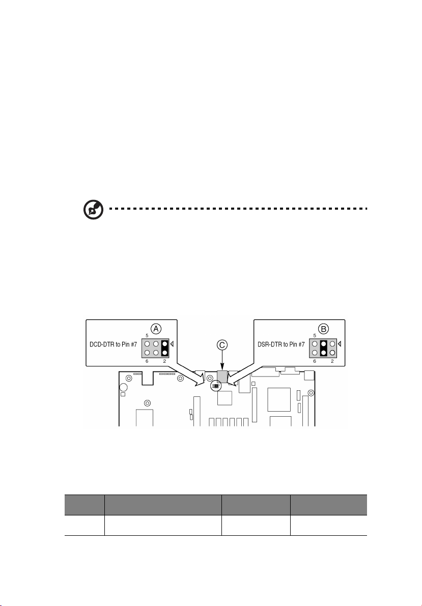
RJ-45 Serial Port
The rear RJ-45 serial port is a fully functional serial port that supports
any standard serial device and provides support for serial
concentrators. For server applications that use a serial concentrator to
access the server management features of the baseboard, a standard 8pin CAT-5 cable from the serial concentrator is plugged directly into
the rear RJ-45 serial port. The 8 pins of the RJ-45 connector can be
configured to match either of two pin-out standards used by serial port
devices. To accommodate either standard, the J5A2 jumper block
located directly behind the rear RJ-45 serial port must be jumpered
appropriately according to the desired standard.
Note: By default, the RJ-45 serial port is configured to support a
DSR signal.
For serial devices that require a DSR signal (default), the J5A2 jumper
must be configured in position 3-4 (See figure below, B).
For serial devices that require a DCD signal, the jumper must be in
position 1-2 (See figure below, A).
For server applications that require a DB9 serial connector, you must
use an 8-pin RJ-45-to-DB9 adapter. The following table defines the pinout required for the adapters to provide RS232 support.
RJ-45 Signal Abbreviation DB9
1 Request to Send RTS 7
Page 26

16
RJ-45 Signal Abbreviation DB9
2 Data Terminal Ready DTR 4
3 Transmitted Data TD 3
4 Signal Ground SGND 5
5 Ring Indicator RI 9
6 Received Data RD 2
7 DCD or DSR DCD/DSR 1 or 6
8 Clear to Send CTS 8
1 Description
Page 27

17
ACPI
The Altos R700 server board supports the Advanced Configuration and
Power Interface (ACPI) as defined by the ACPI 2.0 specification. An
ACPI aware operating system can put the system into a state where the
hard drives spin down, the system fans stop, and all processing is
halted. However, the power supply will still be on and the processors
will still be dissipating some power, so the power supply fans will still
run.
The Altos R700 server board supports sleep states s0, s1, s4, and s5:
• s0: Normal running state.
• s1: Processor sleep state. No context will be lost in this state and
the processor caches will maintain coherency.
• s4: Hibernate or Save to Disk: The memory and machine state are
saved to disk. Pressing the power button or other wakeup event
will restore the system state from the disk and resume normal
operation. This assumes that no hardware changes have been
made to the system while it was off.
• s5: Soft off: Only the RTC section of the CSB and the BMC are
running in this state. No context is saved by the OS or hardware.
Caution: The system is off only when the AC power cord is
disconnected.
Page 28

18
1 Description
System Management
ASMe integrates system management features into the hardware and
provides additional features through ASMe Server Management
software. This section describes the integrated hardware features, Acer
Advance Server Management software, and the System Setup Utility
and FRU/SDR Load Utility used to configure the hardware features.
Baseboard Management Controller
Acer server boards incorporate a baseboard management controller
(BMC), which is a dedicated microcontroller for system management
activities. The BMC performs the following functions:
• Monitors system components and sensors, including processors,
memory, fans, power supplies, temperature sensors, and chassis
intrusion sensors.
• Manages nonvolatile storage for the system event log (SEL), sensor
data records (SDRs), and baseboard field-replaceable unit (FRU)
inventory.
• Interfaces with the emergency management port (EMP) and LAN1
port to send alerts and interact with remote management systems.
• Provides the main front panel control functions (power on/off,
reset, and so on).
Field Replaceable Units and Sensor Data Records
Field replaceable units (FRUs) are major modules in the chassis that
contain active electronic circuitry. FRUs can store information-such as
board serial number, part number, name, and asset tag-that can be
read using the System Setup Utility (see “Viewing FRU Information” on
page 64). The BMC stores FRU information for the baseboard in a
nonvolatile storage component on the board.
The BMC uses Sensor Data Records (SDRs) to identify the sensors in the
system for monitoring. SDRs provide a list of the sensors, their
characteristics, location, type, and type-specific information, such as
default threshold values, factors for converting a sensor reading into
the appropriate units (mV, rpm, degrees Celsius), and information on
the types of events that a sensor can generate. The BMC stores SDR
information in a nonvolatile storage component on the baseboard.
Page 29

19
You can use the FRU/SDR Load Utility (see “FRU/SDR Load Utility
Description” on page 76) to initialize or update the FRU and SDR
information. Acer server boards are shipped from the factory with
some sensors disabled, because the actual configuration of the chassis
is only determined when the user completes the system configuration.
Chassis-specific information in the FRU, such as chassis part number, is
also absent. For these reasons, it is important to run the FRU/SDR Load
Utility as part of the system setup process. You should also run the FRU/
SDR Load Utility whenever you change the number of fans, processors,
or power supplies in the server.
System Event Log
The BMC manages a system event log (SEL), where it records significant
or critical system events. Such events include temperatures and events.
The BIOS, software, and other devices can also log events by sending
messages to the BMC. The SEL is stored in nonvolatile storage.
You can view the current contents of the SEL by using the System Setup
Utility (see “Viewing the System Event Log” on page 63).
Platform Event Management
Events can trigger alerts and other actions by the BMC. The server is
configured with the following set of standard events:
• Temperature sensor out of range
• Voltage sensor out of range
• Fan failure
• Chassis intrusion
• Power supply fault
• BIOS uncorrectable ECC error
• BIOS POST error
• Processor fault resilient booting (FRB) failure
• Fatal nonmaskable interrupt (NMI) from a source other than the
front panel switch
• Watchdog timer reset, power down, or power cycle
• System restart (reboot)
Alerts can take either of these forms:
Page 30

20
1 Description
• Platform event pages -- the BMC dials a paging service and
sends a predefined paging string. To use platform event paging
(PEP), you must attach an external modem to the emergency
management port (Serial 2).
• BMC LAN alerts -- the BMC sends an alert to a predefined
destination on the LAN.
You can configure PEP and BMC LAN alerts by using the System Setup
Utility (see “Alerting for Platform Events” on page 68).
Emergency Management Port
The emergency management port (EMP) refers to the use of the Serial
2 port, with either an external modem or direct serial connection, for
remote management. The BMC controls the port and interfaces with
remote access software, such as the Direct Platform Control application
in Acer Advance Server Management.
You can configure the EMP by using the System Setup Utility (SSU) or
the System Configuration Wizard (SCW).
EMP and Serial Over LAN
The RJ-45 Serial 2 port on the back panel can be configured in several
different ways: as a standard serial port, as an Emergency
Management Port, or for serial output redirection over a LAN. You can
configure these settings using either the SSU or the SCW.
Note:
Important Altos R700 Server Chassis considerations: If you
have configured the Serial 2 port for use as an Emergency
Management Port and “always available”, the Serial 2 port will be
accessible only by remote server management software. The
operating system will never be able to access the port.
If you have configured the Serial 2 port for Serial Over LAN, the
port’s functionality will only be impacted when there is an active
Serial Over LAN session from a remote console. At all other times
either the operating system or EMP will control the port,
depending on your configuration.
Page 31

21
Acer Advance Server Management (ASMe)
Acer Advance Server Management (ASMe) is a system management
package that is included on the ASMe CD. ASMe applications interact
with the integrated hardware system management features of the
server to allow you to monitor and manage a server from a remote
workstation:
• Remote connection from a Windows-based client workstation over
a LAN, or over a modem or direct serial connection to the
emergency management port on the server.
• Real-time monitoring and alerting for server hardware sensors.
• Emergency management when the server is off (but still connected
to AC power) lets you verify the state of the server, diagnose
hardware problems, and power on/off or reset the server.
• Run the System Setup Utility to change the server configuration.
ASMe can use an optional service partition on the server that you are
managing. The service partition is a special disk partition on the system
drive that contains a ROM-DOS operating system and DOS-based
utilities, including the System Setup Utility, FRU/SDR Load Utility, and
Remote Diagnostics. The server can be booted to the service partition,
either locally or remotely, to provide access to the utilities.
For more information on Acer Advance Server Management and the
individual ASMe applications, see the ASMe CD.
Page 32

22
1 Description
Security
Intrusion Switch Monitoring
To help prevent unauthorized entry or use of the server, Acer Advance
Server Management server management software monitors the chassis
intrusion switch if one is installed. Opening an access cover will
transmit an alarm signal to the server board, where BMC firmware and
server management software process the signal. The system can be
configured through ASMe to respond to an intrusion a number of
ways, including powering down or locking the keyboard.
Software Locks
The BIOS Setup and the System Setup Utility (SSU) provide a number of
security features to prevent unauthorized or accidental access to the
system. Once the security measures are enabled, you can access the
system only after you enter the correct password(s). For example:
• Enable the keyboard lockout timer so that the server requires a
password to reactivate the keyboard and mouse after a specified
time out period¾1 to 120 minutes.
• Set and enable a supervisor password.
• Set and enable a user password.
• Set secure mode to prevent keyboard or mouse input and to
prevent use of the front panel reset and power switches.
• Activate a hot key combination to enter secure mode quickly.
• Disable writing to the diskette drive when secure mode is set.
• Disable access to the boot sector of the operating system hard disk
drive.
Using Passwords
You can set either the user password, the supervisor password, or both
passwords. If only the user password is set, you:
• Must enter the user password to enter BIOS Setup or the SSU.
• Must enter the user password to boot the server if Password on
Boot is enabled in either the BIOS Setup or SSU.
Page 33

23
• Must enter the user password to exit secure mode.
If only the supervisor password is set, you:
• Must enter the supervisor password to enter BIOS Setup or the
SSU.
• Must enter the supervisor password to boot the server if Password
on Boot is enabled in either the BIOS Setup or SSU.
• Must enter the supervisor password to exit secure mode.
If both passwords are set, you:
• May enter the user password to enter BIOS Setup or the SSU.
However, you will not be able to change many of the options.
• Must enter the supervisor password if you want to enter BIOS
Setup or the SSU and have access to all of the options.
• May enter either password to boot the server if Password on Boot
is enabled in either the BIOS Setup or SSU.
• May enter either password to exit secure mode.
Secure Mode
Configure and enable the secure boot mode by using the SSU. When
secure mode is in effect:
• You can boot the server and the operating system will run, but you
must enter the user password to use the keyboard or mouse.
• You cannot turn off system power or reset the server from the
front panel switches.
Secure mode has no effect on functions enabled via remote server
management or power control via the watchdog timer.
Taking the server out of secure mode does not change the state of
system power. That is, if you press and release the power switch while
secure mode is in effect, the system will not be powered off when
secure mode is later removed. However, if the front panel power
switch remains depressed when secure mode is removed, the server
will be powered off.
Page 34

24
1 Description
Summary of Software Security Features
The table below lists the software security features and describes what
protection each offers. In general, to enable or set the features listed
here, you must run the SSU and go to the Security Subsystem Group,
menu. The table also refers to other SSU menus and to the Setup
utility.
Feature Description
Secure Mode How to enter secure mode:
• Setting and enabling passwords automatically
places the system in secure mode.
• If you set a hot-key combination (through
Setup), you can secure the system simply by
pressing the key combination. This means you
do not have to wait for the inactivity time-out
period.
When the system is in secure mode:
• The server can boot and run the operating
system, but mouse and keyboard input is not
accepted until the user password is entered.
• At boot time, if a CD is detected in the CDROM drive or a diskette in drive A, the system
prompts for a password. When the password is
entered, the server boots from CD or diskette
and disables the secure mode.
• If there is no CD in the CD-ROM drive or
diskette in drive A, the server boots from drive
C and automatically goes into secure mode. All
enabled secure mode features go into effect at
boot time.
To leave secure mode: Enter the correct
password(s).
Disable writing to
diskette
In secure mode, the server will not boot from or
write to a diskette unless a password is entered.
To write protect access to diskette whether the
server is in secure mode or not, use the Setup
main menu, Floppy Options, and specify Floppy
Access as read only.
Page 35

Feature Description
25
Set a time out period so
that keyboard and
mouse input are not
accepted
Also, screen can be
blanked, and writes to
diskette can be
inhibited
Control access to using
the SSU: set supervisor
password
Control access to the
system other than SSU:
set user password
Specify and enable an inactivity time out period
of from 1 to 120 minutes.
If no keyboard or mouse action occurs for the
specified period, attempted keyboard and mouse
input will not be accepted.
The monitor display will go blank, and the
diskette drive will be write protected (if these
security features are enabled through Setup).
To resume activity: Enter the correct password(s).
To control access to setting or changing the
system configuration, set a supervisor password
and enable it through Setup.
If both the supervisor and user passwords are
enabled, either can be used to boot the server or
enable the keyboard and/or mouse, but only the
supervisor password will allow Setup to be
changed.
To disable a password, change it to a blank entry
or press CTRL-D in the Change Password menu of
the Supervisor Password Option menu found in
the Security Subsystem Group.
To clear the password if you cannot access Setup,
change the Clear Password jumper (see “6
Technical Reference” on page 95).
To control access to using the system, set a user
password and enable it through Setup.
To disable a password, change it to a blank entry
or press CTRL-D in the Change Password menu of
the User Password Option menu found in the
Security Subsystem Group.
To clear the password if you cannot access Setup,
change the Clear Password jumper (see “6
Technical Reference” on page 95).
Boot without keyboard The system can boot with or without a keyboard.
During POST, before the system completes the
boot sequence, the BIOS automatically detects
and tests the keyboard if it is present and displays
a message.
Page 36

26
Feature Description
1 Description
Specify the boot
sequence
The sequence that you specify in setup will
determine the boot order. If secure mode is
enabled (a user password is set), then you will be
prompted for a password before the server fully
boots. If secure mode is enabled and the “Secure
Boot Mode” option is also enabled, the server will
fully boot but will require a password before
accepting any keyboard or mouse input.
Page 37

2 Installation
Procedures
Page 38

28
2 Installation Procedures
Rearrange the Standoffs
If your chassis does not have board mount standoffs placed as shown,
you must rearrange them so they match the holes in the server board.
Failure to properly rearrange the metal standoffs may cause the server
board to malfunction and may permanently damage it. Your chassis
may be different from the illustration.
Page 39

29
Install the Server Board
To ensure proper grounding and support, it is recommended that you
install screws in all the required mounting holes for your chassis. You
may need to move cables out of the way to properly install your server
board.
1 While placing the board on the chassis standoffs, carefully position
the board I/O connectors into the rear chassis I/O openings.
2 Adjust board position to align mounting holes with standoffs.
3 Using the screws that came with your chassis, mount the board to
the chassis.
Note: If you install the server board into an Altos R700 chassis,
you will not use all of the mounting holes. See your chassis
documentation for more details.
Page 40

30
2 Installation Procedures
Install the Processor Retention Brackets
There are four brackets, two for each processor socket. For each
bracket, do the following:
1 Place the bracket (A) on the server board.
2 Insert and tighten two screws (B) to secure the bracket.
Page 41

Installing Processors
1 Raise the locking bar on the socket.
2 Aligning the pins of the processor with the socket, insert the
processor into the socket.
31
Page 42

32
2 Installation Procedures
3 Lower the locking bar completely.
4 Follow the instructions packaged with your boxed processor for
preparing the heat sink and processor for installation.
5 Position the heat sink above the processor.
6 Aligning the raised metal surfaces, place the heat sink on top of
the processor.
7 Place the heat sink clip (1) so the tab on the clip engages the slot
on the heat sink (A).
Page 43

8 Press one end of the clip down (2).
9 Press the other end of the clip down (3).
33
Page 44

34
2 Installation Procedures
Memory
Only DDR-200 or DDR-266 compliant SDRAM is supported by the server
board. Install from 256 MB to 12 GB of registered, ECC memory, using
up to six DIMMs. A 1U chassis requires lowprofile (LP) 1.2-inch DIMMs.
DIMMs must be installed in pairs and in the following order: 1B and
1A, 2B and 2A, 3B and 3A.
Installed DIMMs must be the same speed and must all be registered.
Page 45

Connect Cables
Before connecting cables, consult the documentation supplied with
your chassis.
35
Label Description
A External SCSI channel A connector (SCSI server board only)
B Internal SCSI channel B connector (SCSI server board only)
C Serial 1 header
D Combined Floppy/Front Panel/IDE connector (For use in an Altos
chassis only)
E Fan module connector
F Fan module connector
G Processor fan connectors (For use in a non Altos chassis only)
H Auxiliary power connector
Page 46

36
Label Description
I Main power connector
J Power supply signal connector
K Front panel connector (For use in a non Altos chassis only)
L Floppy connector (For use in a non Altos chassis only)
M IDE connector (For use in a non Altos chassis only)
N USB header
O ATA-100 primary/secondary connectors (ATA server board only)
2 Installation Procedures
Installing a Service Partition on the Server (Optional)
The Service Partition provides advanced remote management and
configuration functionality. Installing it on a server is optional.
1 Power-on the server, insert the Acer Advance Server Management
CD into the CD-ROM drive, and boot to the CD.
2Select Utilities > Run Service Partition Administrator > Create
Service Partition-first time.
3 Select an available hard drive. The server will reboot to the CD.
4Select Format Service Partition and Install Software.
5 Exit the menu. Remove the CD and reboot to install the server
operating system. After installing the operating system, proceed
to Acer Advance Server Management Installation.
Installing your Operating System
Install your operating system now.
Installing Acer Advance Server Management
You can install Acer Advance Server Management on a local server or
on a remote workstation that is used to manage a LAN/WAN.
Page 47

1 Insert the Acer Advance Server Management CD into the system’s
CD-ROM.
2 Click Install Server Management.
3 Select the applicable system option.
4 Review the Acer Software License Agreement and click Accept.
5 If installing to a local server, click Install Now. If this is a multiple
system installation, click Add to compile a list of systems and then
click Install Now.
6Select Reboot Now or Reboot Later.
7 Remove the Acer Advance Server Management CD.
37
Page 48

38
2 Installation Procedures
Page 49

3 Upgrading
Page 50

40
3 Upgrading
Tools and Supplies Needed
• Jumper removal tool or needle nosed pliers
• Phillips† (cross head) screwdriver (#1 bit and #2 bit)
• Pen or pencil
• Antistatic wrist strap and conductive foam pad (recommended)
Page 51

Cautions
These warnings and cautions apply throughout this chapter. Only a
technically qualified person should configure the server board.
Cautions:
System power on/off: The power button DOES NOT completely
turn off the system AC power, 5V standby is still active whenever
the system is plugged in. To remove power from system, you must
unplug the AC power cord from the wall outlet. Make sure the AC
power cord is unplugged before you open the chassis, add, or
remove any components.
Hazardous conditions, devices & cables: Hazardous electrical
conditions may be present on power, telephone, and
communication cables. Turn off the server and disconnect the
power cord, telecommunications systems, networks, and modems
attached to the server before opening it. Otherwise, personal
injury or equipment damage can result.
Electrostatic discharge (ESD) & ESD protection: ESD can
damage disk drives, boards, and other parts. We recommend that
you perform all procedures in this chapter only at an ESD
workstation. If one is not available, provide some ESD protection
by wearing an antistatic wrist strap attached to chassis ground
(any unpainted metal surface) on your server when handling
parts.
41
ESD and handling boards: Always handle boards carefully. They
can be extremely sensitive to ESD. Hold boards only by their
edges. After removing a board from its protective wrapper or
from the server, place the board component side up on a
grounded, static free surface. Use a conductive foam pad if
available but not the board wrapper. Do not slide board over any
surface.
Installing or removing jumpers: A jumper is a small plastic
encased conductor that slips over two jumper pins. Some jumpers
have a small tab on top that you can grip with your fingertips or
with a pair of fine needle nosed pliers. If your jumpers do not
have such a tab, take care when using needle nosed pliers to
Page 52

42
3 Upgrading
remove or install a jumper; grip the narrow sides of the jumper
with the pliers, never the wide sides. Gripping the wide sides can
damage the contacts inside the jumper, causing intermittent
problems with the function controlled by that jumper. Take care
to grip with, but not squeeze, the pliers or other tool you use to
remove a jumper, or you may bend or break the stake pins on the
board.
Page 53

43
Replacing the Back up Battery
The lithium battery on the server board powers the real time clock
(RTC) in the absence of AC power. When the battery starts to weaken,
it loses voltage, and the server settings stored in CMOS RAM in the RTC
(for example, the date and time) may be wrong. Contact your customer
service representative or dealer for a list of approved devices.
To replace the battery:
1 Before proceeding, record your custom BIOS settings.
2 Observe the safety and ESD precautions at the beginning of this
chapter.
3 Open the chassis and locate the battery.
4 Push the upper end of the metal retainer away from the battery-
the battery pops up.
5 Remove the battery from its socket.
6 Dispose of the battery according to local ordinance.
7 Remove the new lithium battery from its package.
8 Being careful to observe the correct polarity, lay the battery in the
socket.
9 Push the battery down-the metal retainer locks the battery in the
socket.
10 Close the chassis.
11 Run Setup to restore the configuration settings to the RTC.
12 Restore your custom BIOS settings.
Page 54

44
3 Upgrading
Page 55

4 Configuration
Software
Utilities
and
Page 56

46
4 Configuration Software and Utilities
Page 57

Service Partition (Optional)
When you are setting up your server system, you can install a service
partition onto your hard drive. The service partition includes utilities,
and other software that be run locally or remotely to assist in system
management. The service partition uses approximately 40 MB of hard
disk space.
Note: It is highly recommended that you install the service
partition before installing an operating system. For more
information, see the Service Partition section in the Installation
Guide for Acer Advance Server Management. This document is
included on the ASMe CD shipped with your server board.
47
Page 58

48
4 Configuration Software and Utilities
Configuration Utilities
System Software Update Sequence
When you update the system software, you should do it in the
following order.
1 Update firmware (BMC & HSC)
2Update FRU/SDR
3 Unplug system for 30 seconds
4Update BIOS
5 Clear CMOS
Configuration Utilities Table:
Utility Description and brief procedure Page
Adaptec SCSISelect
Utility
Direct Platform
Control (DPC) Console
System Setup Utility
(SSU) and Client
System Setup Utility
(CSSU)
BIOS Update Utility Use to update the BIOS or recover from a
Use to configure or view the settings of
the SCSI host adapters and onboard SCSI
devices in the system.
Use to access and monitor the server
remotely.
Use for viewing and configuring server
management options, viewing the
system event log (SEL), setting boot
device priority, or setting system security
options.
The SSU can run either from the
configuration software CD or from a set
of bootable diskettes. You can create the
diskettes from the CD.
The CSSU is run from the service
partition via the DPC console. It provides
the same functionality as the SSU, but
from a remote console.
Information entered via the SSU/CSSU
overrides information entered via BIOS
Setup.
corrupted BIOS update.
54
57
59
65, 75
Page 59

Utility Description and brief procedure Page
49
Firmware Update
Utility
FRU/SDR Load Utility Use to update the Field Replaceable Unit
Use to update BMC flash ROM or other
firmware.
(FRU) and Sensor Data Record (SDR) flash
components.
NOTE: You must run the FRU/SDR Load
utility whenever the BMC is updated or if
you change your processors.
76
76
Page 60

50
4 Configuration Software and Utilities
Hot Keys
Use the numeric pad of the keyboard to enter numbers and symbols.
To Do T h i s : Press These Keys
Secure your system immediately. <Ctrl+Alt>+hot key (Set your hot key
combination with the SSU or BIOS
Setup)
Enter the Adaptec SCSI Utility
during POST.
Enter BIOS Setup during POST. <F2>
Abort memory test during POST. <ESC> (Press while BIOS is updating
Display a menu for selecting the
boot device.
To remove the splash screen. <ESC>
<Ctrl+A> (SCSI version only)
memory size on screen)
<ESC> (Press anytime after memory
check)
Page 61

51
Power-On Self-Test (POST)
Each time you turn on the system the BIOS begins execution of the
Power-On Self-Test (POST). POST discovers, configures, and tests the
processors, memory, keyboard, and most installed peripheral devices.
The time needed to test memory depends on the amount of memory
installed. POST is stored in flash memory.
1 Turn on your video monitor and system. After a few seconds, POST
begins to run and displays a splash screen.
2 While the splash screen is displayed:
• Press <F2> to enter the BIOS Setup (see “BIOS Setup”)
OR
• Press <Esc> to view POST diagnostic messages and change the
boot device priority for this boot only (see “Temporarily
Changing the Boot Device Priority” on page 52).
3 After pressing <F2> or <Esc> during POST, you can press <Ctrl+A>
to run the SCSISelect Utility. For more information, see“Running
the Adaptec SCSISelect Utility” on page 54.
4 If you do not press <F2> or <Esc> and do NOT have a device with
an operating system loaded, the boot process continues and the
system beeps once. The following message is displayed:
“Operating System not found”
5 At this time, pressing any key causes the system to attempt a
reboot. The system searches all removable devices in the order
defined by the boot priority.
Page 62

52
4 Configuration Software and Utilities
BIOS Setup
You can run BIOS Setup with or without an operating system being
present. BIOS Setup stores most of the configuration values in batterybacked CMOS; the rest of the values are stored in flash memory. The
values take effect when the system is booted. POST uses these values to
configure the hardware. If the values and the actual hardware do not
agree, POST generates an error message.
Record BIOS Setup Settings
Record your BIOS Setup settings. If default values ever need restoring
(after a CMOS clear, for example), you must run BIOS Setup again. Your
record will make this much easier.
If BIOS Setup Is Inaccessible
If you have a misconfigured diskette drive, and you cannot use BIOS
Setup to correct the problem, you might need to clear CMOS memory.
To clear CMOS, either of two methods can be used.
1 Press the reset button and hold it down for four seconds or more,
and then, while holding the reset button down, press the power
button. Release both buttons at the same time.
2 Move the Clear CMOS jumper found on the configuration jumper
block on the baseboard.
Temporarily Changing the Boot Device Priority
During POST, you can change the boot device priority for the current
boot process. The changes are not saved for the next boot process.
1 Boot the server.
2 At any time during POST, press <Esc>. When POST completes, a
popup Boot menu displays.
3 Use the arrow keys to highlight the device you want the server
system to boot from first. For example, if you want the server
system to boot from the CD-ROM first, you select “ATAPI CD-ROM
Drive.”
Note: One of the selections on the popup Boot menu is “Enter
Setup.” Selecting this option brings you into the BIOS Setup.
Page 63

4Press <Enter>.
5 The boot process continues. When finished, a system prompt
displays.
53
Page 64

54
4 Configuration Software and Utilities
Running the Adaptec SCSISelect Utility
Each host adapter includes an onboard SCSISelect configuration utility
that allows you to configure/view the settings of the host adapter and
devices in the server.
The system finds the Adaptec SCSI host adapter and displays the
message Adaptec SCSI BIOS V x.xxx where x.xxx is the version number
of the SCSISelect utility.
Pressing <Ctrl+A> at this time allows you to configure the Adaptec AIC7XXX SCSI host adapter.
When to Run the Adaptec SCSISelect Utility
Use the SCSISelect utility to:
• Change default values
• Check and/or change SCSI device settings that may conflict with
those of other devices in the server
• Do a low-level format on SCSI devices installed in the server
Running the SCSISelect Utility
1 When this message appears on the video monitor:
<<<Press <Ctrl><A> for SCSISelect(TM) Utility!>>>
2 Press <Ctrl+A> to run the utility. When the main menu for the host
adapter appears, choose the device that you want to configureeach SCSI bus accepts up to 15 devices.
Use the following keys to navigate through the menus and submenus:
Press To
ESC Exit the utility
Enter Select an option
↑ Return to previous option
↓ Move to the next option
Page 65

Press To
F5 Switch between color and
monochrome
F6 Reset to host adapter defaults
Configuring the Adaptec SCSI Adapter
The Adaptec SCSI adapter has two busses. Select the bus from the
following menu:
Menu Item Options
55
You have an adapter in your system.
Move the cursor to the bus:device:channel of
the one for configuration and press Enter.
<F5> - Toggle color/monochrome.
Bus:Device:Channel
01:06:A
01:06:B
After selecting the bus, the following menu displays:
Host Adapter Option Comment
AIC-7XXX at
Bus:Device:Channel
01:06:A (or 01:06:B)
Configure/View
Host Adapter
Settings
SCSI Distk
Utilities
Press Enter to view the
Configuration Menu.
Press Enter to view the SCSI Disk
Utilities Menu. This menu allows
you to format hard disks and/or
verify disk media.
Page 66

56
4 Configuration Software and Utilities
When you are finished, press Esc> and make your selection from the
following menu:
Feature Option Comment
Exit Utility? Yes
No
When you finish configuring your SCSI
devices, press Esc. Then select Yes and press
Enter. When this message appears:
Please press any key to reboot.
Press any key, and the server reboots.
Page 67

57
Direct Platform Control (DPC) Console
Direct Platform Control (DPC) Console is part of Acer Advance Server
Management. Direct Platform Control is a server management
application that supports remote system management via LAN, or an
RS-232 serial connection to the server serial 2 port over a modem or a
direct serial cable. The Direct Platform Control Console provides the
ability for remote management of Acer servers via modem or LAN with
a capability to run DOS-based programs.
DPC console runs on a client workstation. It communicates with a
server by:
• Accessing the server management capabilities of the on-board NIC
• A Windows 2000 compatible modem.
• An RS-232 connection to the server’s serial 2 port.
DPC Console is independent of the server operating system.
Even when the server is off, you can use DPC Console to verify the state
of a server or diagnose a problem with the server hardware. DPC
console features allows you to:
• Establish connection to remote servers
• Server Control: power on, power off, and reset operations
• Retrieve and display entries in the System Event Log (SEL)
• Retrieve and display Sensor Data Records (SDR)
• Retrieve and display Field Replaceable Unit (FRU) information
• Retrieve and display current Remote Sensor Access (RSA)
information
• Access a phone book for remote connection management
• Remote control of the service partition
• File transfer from / to the server
DPC Console Modes of Operation
There are four DPC console modes of operation:
• EMP mode. Access the DPC console features using the DPC console
window menus and/or toolbar. Active when a connection is
established through the EMP port.
Page 68

58
• DPC over LAN mode. Access the DPC console features using the
DPC console window menus and/or toolbar. Active when a
connection is established through the LAN.
• Re-direct mode. Active when the server is running BIOS console
redirection. In this mode, the DPC console launches a separate
window. The window operates as an ANSI terminal and
communicates with the server through the port. Character-based
commands you type in the DPC Console go directly to the server,
and the DPC Console displays the text that you would normally see
on the server console.
To use this mode, you must configure the Console Redirection
option of BIOS Setup for Redirect mode. Enabling Console
Redirection requires that the Boot Time Diagnostics Screen be
Enabled in BIOS Setup. If the redirection window does not display
information, the Console Redirection is either incorrectly
configured or disabled, the EMP is disabled in BIOS Setup, or the
server is in protected mode. For DPC to function, the server must
NOT be in graphics mode.
• If the DPC console fails to connect in EMP within 10 seconds and
the server can operate in Redirect mode, a prompt is displayed
with the option to switch to Re-direct mode.
• Service Partition mode. Entered when the server reboots from the
service partition and the DPC Console has successfully connected to
the server through a modem. This mode allows running of DOSbased programs that are stored on the service partition and
transferring of files.
4 Configuration Software and Utilities
Running the DPC Console
For more information about setting up and running the DPC Console,
see the document named “ASMe_Install_Guide.pdf.” This document is
in the ASMe\DOCS directory on the ASMe CD accompanying the Altos
R700 server board.
Page 69

59
Using the System Setup Utility
The System Setup Utility (SSU) is located on the System Resource CDROM shipped with the server.
Run the System Setup Utility to:
• Set boot device priority
• Set passwords and security options
• View system events
• View FRU information
• View sensor data records
• Update system firmware and BIOS
• Save and restore the system configuration
• Set up the server to send alerts for platform events
• Set up the server for remote management
Using either the System Setup Utility or BIOS Setup, you can specify the
boot device sequence and set up system passwords and security
options. Both utilities access the same stored configuration data for
these items, and the result of making a change to these settings using
either utility is identical.
The SSU consists of a collection of task-oriented modules plugged into
a common framework called the Application Framework (AF). The
Application Framework provides a launching point for individual tasks
and a location for setting customization information.
Creating SSU Diskettes
You can run the SSU directly from the Utilities menu of the System
Resource CD-ROM, from a set of DOS diskettes, or from the service
partition of the hard disk.
If you choose to run the SSU from a set of DOS diskettes, you must
create the SSU diskettes from the Resource CD-ROM as follows:
1 Boot to the System Resource CD-ROM.
2 Choose Create Diskettes > Create Diskettes by Device/Function >
System Setup Utility.
3 Follow the instructions displayed.
Page 70

60
Alternatively, if you have a workstation with the Microsoft Windows
operating system, you can insert the CD into that system and create the
diskettes on that system.
4 Configuration Software and Utilities
Running the SSU
When the SSU starts in the default local execution mode, the SSU
accepts input from the keyboard or mouse. The SSU presents a VGAbased GUI on the primary monitor.
If you run the SSU from read-only media, such as the CD-ROM, you
cannot save user preference settings (such as screen colors).
The SSU supports ROM-DOS version 6.22. The SSU will not operate
from a “DOS box” running under an operating system such as
Windows.
Start the SSU using one of the following methods:
• From diskettes: Insert the first SSU diskette in drive A and boot the
server from the diskette.
You are prompted to insert the second diskette. After loading
completes the SSU starts automatically.
• From the System Resource or ASMe CD-ROM: Boot the server to
the System Resource CD and start the SSU from the Utilities menu.
• From the Service Partition: Boot the server to the Service Partition
and execute the following DOS commands:
C:\> cd ssu
C:\SSU> ssu.bat
The mouse driver loads if it is available; press Enter to continue.
When the SSU title appears on the screen, press Enter to continue.
Working with the SSU Interface
You can access features of the SSU interface using the mouse or
keyboard:
• Mouse-Click once to choose menu items and buttons or to select
items in a list, such as the Available Tasks list. To run a list item,
such as one of from the Available Tasks list, select the item and
click OK or double-click the item.
Page 71

61
• Keyboard-Use the tab and arrow keys to highlight buttons and
press the spacebar or Enter to execute. You can also execute a
menu or button by using the Alt key in combination with the
underlined letter in the name of the menu or button.
You can have more than one task open at the same time, although
some tasks might require complete control to avoid possible conflicts.
The tasks achieve complete control by keeping the task as the center of
operation until you close the task window.
The SSU has a build-in help system, which you access by clicking a Help
button or choosing the Help menu.
Customizing the SSU Interface
The SSU lets you customize your interface using the Preferences section
of the main window. The AF sets these preferences and saves them in
the AF.INI file so that they take effect the next time you start the SSU.
There are four user customizable settings:
• Color-lets you change the default colors associated with different
items on the screen using predefined color combinations. The
color changes take effect immediately.
• Mode-lets you set the desired expertise level: novice, intermediate,
or expert. The expertise level determines which tasks are visible in
the Available Tasks section and which actions each task performs.
For a new mode setting to take effect, you must exit the SSU and
restart it.
• Language-lets you change the text in the SSU to the appropriate
language. For a new language setting to take effect, you must exit
the SSU and restart it.
• Other-lets you show or hide the status bar at the bottom of the
SSU main window. The change takes effect immediately.
Note: If you run the SSU from read-only media (CD-ROM, for
example), these preferences are lost when you exit the SSU.
Exiting the SSU
Exiting the SSU closes all SSU windows.
Page 72

62
4 Configuration Software and Utilities
Setting Boot Device Priority
To change the boot priority of a device:
1 From the SSU Main window, choose Boot Devices.
2 In the Multiboot Options Add-in window, select a device.
3 Click the Move Up button to move it up in the list. Click the Move
Down button to move it down.
Setting Passwords and Security Options
You can set a user password and an administrator password. On some
systems, you must set an administrator password before you can set a
user password. On other systems, the passwords are independent. You
can set the same passwords and security options by using BIOS Setup.
Setting the Administrator Password
The Admin Password button lets you set or change the administrator
password used by both the SSU and the system BIOS. This option is not
available if both an administrator and a user password are set and you
entered only the user password when you started the SSU. All changes
to the administrator password take effect immediately.
To change or clear the administrator password:
1 From the SSU Main window, choose Security.
2 Click the Admin Password button.
3 If you are changing passwords, enter the old password.
4 Enter the new password (or leave blank to clear).
5 Confirm the password by entering it again (or leave blank to
clear).
6 Click OK to save the password and return to the Security window.
Setting the User Password
The User Password button lets you set or change the user password
used by both the SSU and the system BIOS. All changes to the user
password take effect immediately.
To change or clear the user password:
Page 73

1 From the SSU Main window, choose Security.
2 Click the User Password button.
3 If you are changing passwords, enter the old password in the first
box.
4 Enter the new password (or leave blank to clear).
5 Confirm the password by entering it again (or leave blank to
clear).
6 Click OK to save the password and return to the Security window.
Setting Security Options
For a description of security features, see “Security” on page 22.
To set the security options:
1 In the Security window, click the Options button.
2 For each option, select the desired setting from the list. The
options are:
• Security Hot Key: The key combination that can be used to
put the server into secure mode.
• Secure Mode Timer: If no keyboard or mouse activity occurs
during the chosen time interval, the server enters secure
mode.
• Secure Mode Boot: Enable forces the server to boot directly
into secure mode.
• Video Blanking: Enable turns off the video when the server is
in secure mode.
• Floppy Write: Enable prevents writing to the diskette drive
while the server is in secure mode.
• Power Switch Inhibit: Enable prevents the power and reset
buttons from functioning when the server is in secure mode.
Disable allows the power and reset buttons to function
normally when the server is in secure mode.
3 Click Save to save the settings and return to the Security window.
63
Viewing the System Event Log
To view the System Event Log (SEL):
Page 74

64
1 From the SSU Main window, choose SEL Manager.
When you start the SEL Manager, it automatically loads the current
list of events from nonvolatile memory.
2 Use the F4 and F5 keys to scroll the window contents to the left
and right to view all of the columns.
3 Use the File and SEL menu items to work with the SEL information:
• Open: Views data from a previously saved SEL file.
• Save As: Saves the currently loaded SEL data to a file.
• Properties: Displays information about the SEL.
• Clear SEL: Clears the SEL data from the nonvolatile storage
area.
• Reload: Refreshes the display by reading the current SEL
entries from the server.
• Sort By: Sorts the displayed events by event number, time
stamp, sensor type and number, event description, or event
generator ID.
4 Configuration Software and Utilities
Viewing FRU Information
To view the Field Replaceable Unit (FRU) information:
1 From the SSU Main window, choose FRU Manager.
When you start the FRU Manager, it automatically loads the
current list of events from nonvolatile memory.
The FRU Manager window has a navigation pane on the left that
displays, in a tree format, the inventory of components in the
server. The tree has three categories: Chassis, Board, and Product.
Clicking on a category expands or collapses a list of components
for that category. Clicking on an individual component displays the
FRU information for that component in the presentation pane in
the upper right. The description pane in the lower right displays a
description of the currently selected FRU area.
2 Use the F4 and F5 keys to scroll the window contents to the left
and right to view all of the columns.
3 Use the File and FRU menu items to work with the FRU
information:
• Open: Views data from a previously saved FRU file.
Page 75

65
• Save As: Saves the currently loaded FRU data to a file.
• Properties: Displays the number of FRU devices in the system and
the number being displayed. Only FRU devices with valid FRU areas
are displayed.
• Reload: Refreshes the display by reading the current FRU entries
from the server.
Viewing Sensor Data Records
To view the Sensor Data Records (SDR):
1 From the SSU Main window, choose SDR Manager.
When you start the SDR Manager, it automatically loads the SDR
entries from non-volatile memory.
The SDR Manager window has a navigation pane on the left that
displays, in a tree format, the sensor data records. The tree has
categories for each type of record. Clicking on a category expands
or collapses a list of SDRs for that category. Clicking on an
individual SDR displays the information for that SDR in the
presentation pane in the upper right. The description pane in the
lower right displays a description of the currently selected SDR
type.
2 Use the F4 and F5 keys to scroll the window contents to the left
and right to view all of the columns.
3 Use the File and SDR menu items to work with the SDR
information:
• Open: Views data from a previously saved SDR file.
• Save As: Saves the currently loaded SDR data to a file.
• Properties: Displays information about the SDR, including IPMI
version, number of SDR entries, time stamps for changes to the
SDR information, and free space remaining.
• Reload: Refreshes the display by reading the current SDR entries
from the server.
Updating System Firmware and BIOS
Using the SSU, you can update the BIOS, update the firmware, and
verify the firmware. Procedures for each are given below. You can also
update the BIOS and firmware without using the SSU.
Page 76

66
4 Configuration Software and Utilities
Updating the BIOS
To update the BIOS:
1 Download the update from the Acer support website.
2 From the SSU Main window, choose System Update. (System
Update is available only in Expert mode.)
When you start System Update, it automatically displays the
current revision information for the system firmware and BIOS.
3 From the File menu, choose Load and choose a .uif or .bio file to
use for the update.
4 Click the Update button to update the BIOS.
Updating the Firmware
To update the system firmware:
1 Download the update from the Acer support website.
2 From the SSU Main window, choose System Update. (System
Update is available only in Expert mode.)
When you start System Update, it automatically displays the
current revision information for the system firmware and BIOS.
3 From the File menu, choose Load and choose a .uif or .hex file to
use for the update.
4 Click the Update button to perform the update.
Verifying the Firmware
To compare the system firmware in nonvolatile memory with a
firmware file:
1 Download the update from the Acer support website.
2 From the SSU Main window, choose System Update. (System
Update is available only in Expert mode.)
When you start System Update, it automatically displays the
current revision information for the system firmware and BIOS.
3 From the File menu, choose Load and choose a .hex file to use for
the update.
4 Click the Verify button to compare the firmware code in
nonvolatile storage with the selected file.
Page 77

Saving and Restoring the System Configuration
Using the SSU, you can save the following configuration information
to a file:
• Platform type, BIOS revision, and firmware revision
• CMOS settings
• Extended system configuration data (ESCD)
• Settings for the emergency management port (EMP), platform
event paging (PEP), and BMC LAN alerts
Data is saved from all sources. There is no way to choose only certain
pieces of configuration data to save. You can also restore the
information from a saved configuration file.
Note: BIOS passwords are stored in the file. Restoring a
configuration can change passwords on a server. EMP and LAN
passwords are not stored in the file.
Saving a Configuration
To save the system configuration:
1 From the SSU Main window, choose Config Save/Restore.
(Configuration Save/Restore is available only in Expert mode.)
2 Click Save To File and specify a filename and location.
67
Restoring a Configuration
To restore the system configuration from a file:
1 From the SSU Main window, choose Config Save/Restore.
(Configuration Save/Restore is available only in Expert mode.)
2. Click Restore from File and specify a filename and location.
The CSR reads the platform type, BIOS revision, and firmware
revision from the file and compares that information with the
same information retrieved from the server. If the two do not
match, an error message is displayed and the restore operation
aborts. If they do match, the CSR restores the configuration data
to the server. It prompts you to reboot the server for the new
settings to take effect.
Page 78

68
4 Configuration Software and Utilities
Alerting for Platform Events
You can set up the server to alert you when various events occur. Alerts
can be delivered either as telephone pages or over the LAN.
Instructions for setting up both telephone paging alerts and LAN alerts
are given below.
Setting Up Paging Alerts
To set up the server to send alerts as telephone pages:
1 Install an external modem on the Emergency Management Port
(serial 2).
2 From the SSU Main window, choose Platform Event Manager
(PEM).
3 In the PEM window, click Configure EMP.
4 In the corresponding boxes, enter the following command strings
for the modem attached to the EMP port (boxes that aren’t listed
here are not required for paging alerts):
• ESC Sequence: the escape sequence. This string is sent to the
modem before sending command strings. The maximum
length for the string is five characters; longer strings are
truncated.
• Hangup String: hang up or drop the connection. The EMP
automatically sends an <ENTER> character following this
string. The maximum length for the string is eight characters;
longer strings are truncated.
• Modem Dial Command: the command to dial a phone
number. This string is sent to the modem before sending the
paging string.
• Modem Init String: the initialization string for the modem.
This string is sent every time the EMP initializes. The maximum
length for the string is determined at run-time from firmware.
You will be notified if the string is truncated. Following a save,
the actual string saved is displayed in the edit box.
5 Click Save to save the changes.
6 Click Close to return to the PEM window.
7 In the PEM window, click Configure PEP.
8 Select the Enable PEP check box.
Page 79

9 In the Blackout Period box, enter the minimum time, in minutes,
between successive pages. The valid range is [0 - 255] where 0
disables the blackout period. Setting a blackout period can save
you from being flooded with repeat pages. After you receive a PEP
page, no additional pages are sent by PEP for the duration of the
blackout period.
10 In the Paging String box, enter the phone number to dial for the
page and the message you want sent with the page. The maximum
length for the paging string is determined at run-time from
firmware. You will be notified if the string is truncated. Following
a save, the actual string saved is displayed in the edit box.
11 From the Options menu, choose Configure Event Actions.
12 In the Platform Event Paging Actions window, move the events
that you want to generate an alert to the Enabled column and
move all other events to the disabled column using the following
buttons:
• >>: Moves all events from the enabled list to the disabled list.
• >: Moves the selected event from the enabled list to the
disabled list.
• <: Moves the selected event from the disabled list to enabled
the list.
• <<: Moves all events from the disabled list to the enabled list.
13 Click Save to save the changes.
14 Click Close to return to the PEP Configuration window.
15 To send a test page to verify that you have correctly configured
PEP, from the Options menu, choose Send Alert.
16 Click Save to save the configuration.
17 Click Close to return to the Platform Event Manager window.
69
Setting Up LAN Alerts
To set up the server to send alerts over the LAN:
1 Configure the remote system to receive alerts. For more
information, see the documentation for Acer Advance Server
Management software.
2 From the SSU Main window, choose Platform Event Manager
(PEM).
Page 80

70
4 Configuration Software and Utilities
3 In the PEM window, click Configure LAN and fill in the boxes
described in the following steps (boxes that aren’t listed here are
not required for LAN alerts).
4 Select the Enable LAN Alerts check box.
5 (Optional) In the SNMP Community String box, enter a string for
the community field in the Header section of the SNMP trap sent
for an alert. The string must be from 5 to 16 characters.
The default string is public.
6 In the IP Setup box, choose either:
• DHCP: the IP address for the server is automatically assigned
by the DHCP (dynamic host control protocol) server on the
network. The Host, Gateway, and Subnet Mask boxes in the
dialog are ignored.
• Static: assign the IP address for the server using the Host,
Gateway, and Subnet Mask boxes in the dialog.
7 If you chose Static IP Setup in the previous step, fill in the IP
addressing boxes:
• Host IP Address: the IP address of this server.
• Gateway IP Address: the IP address of the router for this
server.
• Subnet Mask: the IP address for the server’s subnet. The server
uses this to decide if the alert destination is on the same
subnet.
8 In the Alert IP Address box, fill in the IP address of the system you
want to receive alerts from this server. If you want the alert to be
broadcast to an entire subnet, enter the IP address for the subnet.
9 From the Options menu, choose Configure Event Actions.
10 In the BMC LAN Alerting Actions window, move the events that
you want to generate an alert to the Enabled column and move all
other events to the disabled column using the following buttons:
• >>: Moves all events from the enabled list to the disabled list.
• >: Moves the selected event from the enabled list to the
disabled list.
• <: Moves the selected event from the disabled list to enabled
the list.
• <<: Moves all events from the disabled list to the enabled list.
Page 81

71
11 Click Save to save the changes.
12 Click Close to return to the BMC LAN Configuration window.
13 To send a test alert to verify that you have correctly configured
BMC LAN alerts, from the Options menu, choose Send Alert.
14 Click Save to save the changes.
15 Click Close to return to the PEM window.
Managing the Server Remotely
You can set up the server so that you can connect to it from a remote
client system to perform management tasks. You can make the
connection over a LAN or by using a modem or direct serial cable to
the Emergency Management Port (EMP). Instructions for setting up the
server for remote LAN and serial/modem access are given below.
Setting Up Remote LAN Access
To configure remote LAN access:
1 From the SSU Main window, choose Platform Event Manager
(PEM).
2 In the PEM window, click Configure LAN and fill in the boxes
described in the following steps (boxes that aren’t listed here are
not required for remote access).
3 To require a password for remote access, enter the password in the
Enter New Password box and in the Verify New Password box.
Passwords can be from 1 to 16 characters long, using any ASCII
character in the range [32-126]. To clear the passwords, leave both
boxes blank. (You can also clear the password by choose the menu
Options > Clear LAN Password.)
4 From the LAN Access Mode list, select the remote access mode:
• Full Access: a remote system can initiate a LAN connection
regardless of the state or health of the server.
• Restricted: a remote system can initiate a LAN connection,
but cannot perform control operations such as power down,
reset, or front panel NMI.
• Disabled: remote systems are not allowed to initiate LAN
connections.
5 In the IP Setup box, choose either:
Page 82

72
• DHCP: the IP address for the server is automatically assigned
by the DHCP (dynamic host control protocol) server on the
network. The Host, Gateway, and Subnet Mask boxes in the
dialog are ignored.
• Static: assign the IP address for the server using the Host,
Gateway, and Subnet Mask boxes in the dialog.
6 If you chose Static IP Setup in the previous step, fill in the IP
addressing boxes:
• Host IP Address: the IP address of this server.
• Gateway IP Address: the IP address of the router for this
server.
• Subnet Mask: the IP address for the server’s subnet. The
server uses this to decide if the alert destination is on the same
subnet.
7 Click Save to save the changes.
8 Click Close to return to the PEM window.
4 Configuration Software and Utilities
Setting Up Remote Modem or Serial Access
To configure remote modem or serial access:
1 From the SSU Main window, choose Platform Event Manager
(PEM).
2 In the PEM window, click Configure EMP and fill in the boxes
described in the following steps (boxes that aren’t listed here are
not required for remote access).
3 To require a password for remote access, enter the password in the
Enter New Password box and in the Verify New Password box.
Passwords can be from 1 to 16 characters long, using any ASCII
character in the range [32-126]. To clear the passwords, leave both
boxes blank. (You can also clear the password by choose the menu
Options > Clear LAN Password.)
4 In the Modem Ring Time box, enter the number of 500ms intervals
that the BMC should wait before taking control of the serial 2 port
and answering an incoming call. A value greater than zero gives
the BIOS time to answer before the BMC takes control. A value of
zero causes the BMC to answer immediately. The maximum value,
63, tells the BMC to ignore the call. Modem Ring Time applies only
to Preboot access mode and is ignored for other access modes.
Page 83

73
5 In the System Phone Number box, enter the number for the phone
line connected to the modem on the EMP.
6 From the Access Mode list, choose the remote access mode:
• Always Active: the EMP is available at any time.
• Preboot: the EMP is available only when the server is
powered down or is in the running POST during startup.
• Disabled: remote systems are not allowed to initiate
connections.
7 From the Restricted Mode list, choose either:
• Enabled: a remote system can initiate a connection, but
cannot perform control operations such as power down, reset,
or front panel NMI.
• Disabled: the remote system has full control of the server.
8 From the Connection Mode list, choose either:
• Direct Connect: the serial 2 port on the server is connected
by a serial cable to the remote system.
• Modem Connect: the serial 2 port on the server is connected
to a modem.
9 Click Save to save the changes.
10 Click Close to return to the PEM window.
Page 84

74
4 Configuration Software and Utilities
Software Updates
Your system comes with preinstalled system BIOS and BMC firmware.
Creating a Bootable Diskette
Each update diskette created must be made bootable with ROM-DOS
Ver. 6.22 or MS-DOS Ver. 6.22.
Note: It is recommended that the target system be booted with
the Resource CD that accompanied the product. However, the
process for making the diskettes is the same for all the compatible
versions of DOS. ROM-DOS Ver. 6.22 is included on the Resource
CD.
1 Insert and boot to the Resource CD.
2 Exit from the menu to a DOS prompt.
3 Insert a diskette into the floppy drive.
4 At the DOS prompt, for an unformatted diskette, type:
format a:/s
or, for a formatted diskette, type:
sys a:
5 Press Enter.
Software Update Package
1 Download the software update.
2 Print, review, and follow the instruction file (it supercedes any
other instructions).
Note: Be sure to record the current custom BIOS settings. They
will be cleared and reset to their default values during the BIOS
update portion of the operation. You will need these settings to
configure your computer at the end of the update procedure. To
record the current custom settings, boot the computer and press
F2 when you see the splash screen. Write down the current
custom settings in the BIOS Setup program.
Page 85

Recovering the BIOS
It is unlikely that anything will interrupt the BIOS upgrade; however,
an interruption could damage the BIOS. The following steps explain
how to recover the BIOS if an upgrade fails. The following procedure
uses recovery mode for the Setup program.
Note: Because of the small amount of code available in the nonerasable boot block area, there is no video support. You will not
see anything on the screen during the procedure. Monitor the
procedure by listening to the speaker and looking at the floppy
drive LED.
1 Turn off all connected peripherals, turn off system power, and
disconnect the AC power cord.
2 Remove the access cover and expose the server board. For
instructions, see the product guide accompanying your chassis.
3 Move the Recovery Boot (RCVRY BOOT) jumper from its normal
position to the BIOS recovery position (see “Server Board Jumpers”
on page 97).
4 Reinstall the access cover and connect the power cord.
5 Insert the diskette holding the BIOS upgrade and recovery files
into drive A.
6 Turn on system power and listen to the speaker:
• Two beeps indicate successful BIOS recovery-Go to the next
step.
• A series of continuous beeps indicates failed BIOS recoveryReturn to Step 1 and repeat the recovery process.
7 Turn off system power and disconnect all AC power cords.
8 Remove the access cover.
9 Move the Recovery Boot jumper back to its normal position.
10 Reinstall the access cover.
11 Connect all AC power cords and turn on system power.
75
Page 86

76
4 Configuration Software and Utilities
Firmware Update Utility Description
The Firmware Update Utility is a DOS-based program used to update
the BMCs firmware code. You need to run the utility only if new
firmware code is necessary.
Running the Firmware Update Utility
Review the release notes before proceeding.
1 Create a DOS-bootable diskette. The version of DOS must be 6.22
or higher.
2 Place the firmware update utility (FWUPDATE.EXE) and the *.hex
file on the diskette. Make a note of the *.hex file name, because
you will need it later.
3 Insert the diskette into the drive and boot to it.
4 At the DOS prompt, run the executable file (FWUPDATE.EXE).
5 The utility displays a menu screen. Select Upload Flash.
6 The utility asks for a file name. Enter the name of the *.hex file.
7 The program will load the file and then ask if it should upload
boot code. Press N to continue unless otherwise directed by the
release notes or an Acer support professional.
8 The program next asks if it should upload operational code. Press
Y to continue. The process of uploading operational code takes a
few minutes.
9 Once the operational code updates and verifies, press any key to
continue. Then press ESC to exit the program.
10 Shut the system down and remove any diskettes in the system.
11 Disconnect the AC power cord from the system and wait 30
seconds.
12 Reconnect the AC power cord and power up the system.
FRU/SDR Load Utility Description
The Field Replaceable Unit (FRU) and Sensor Data Record (SDR) load
utility is a DOS-based program used to update the server management
subsystem’s product level FRU and SDR nonvolatile storage
components (EEPROMs). The utility:
Page 87

77
• Discovers the product configuration based on instructions in a
master configuration file
• Displays the FRU information
• Updates the EEPROM associated with the Baseboard Management
Controller (BMC) that holds the SDR and FRU area
• Generically handles FRU devices that might not be associated with
the BMC
What You Need to Do
Either run the utility directly from the Resource CD or from diskettes
created from the CD.
If you run the FRU/SDR Load Utility from a diskette, copy the utility
from the CD. Follow the instructions in the included README.TXT file.
If the diskette drive is disabled, or improperly configured, use BIOS
Setup to enable it. If necessary, disable the drive after you are done
with the FRU/SDR Load Utility.
How You Use the FRU/SDR Load Utility
The utility:
• Is compatible with ROM-DOS Ver. 6.22, MS-DOS Ver. 6.22 (and later
versions), Windows 95 DOS, and Windows 98 DOS
• Accepts CFG, SDR, and FRU load files (the executable file for the
utility is FRU/SDR.exe)
• Requires the following supporting files:
• One or more .fru files describing the system’s field replaceable
units
• A .cfg file describing the system configuration
• An .sdr file describing the sensors in the system
Command Line Format
If you are not performing an automated update using a Software
Update Package (SUP), the basic command line format is:
FRU/SDR [-?] [-h] [-d {fru, sdr}] [-cfg filename.cfg] [-fru
filename.fru]
Page 88

78
4 Configuration Software and Utilities
Command Line Format table:
Command Description
-? or -h Displays usage information.
-d {fru, sdr} Displays requested area only.
-cfg filename.cfg Uses custom CFG file.
-p Pause between blocks data.
Parsing the Command Line
The FRU/SDR load utility allows only one command line function at a
time. A command line function can consist of two parameters.
Example: -cfg filename.cfg. Invalid parameters cause an error message
and exit the program. You can use either a slash (/) or a minus sign (-)
to specify command line options. Use the -p and flags with any of the
other options.
Displaying a Given Area
When the utility is run with the -d FRU or -d SDR command line flag,
information about each area is read from memory and printed on the
screen. Each area represents one sensor for each instrumented device
in the server. If the given display function fails because of an inability
to parse the data present or a hardware failure, the utility displays an
error message and exits.
Using Specified CFG File
Run the utility with the command line parameter of -cfg filename.cfg.
The filename can be any DOS-accepted, eight-character filename
string. The utility loads the specified CFG file and uses the entries in
that file to probe the hardware and to select the proper SDRs to load
into nonvolatile storage.
Displaying Utility Title and Version
The utility displays its title:
FRU & SDR Load Utility, Version Y.Y, Revision X.XX where Y.Y is the
version number and X.XX is the revision number for the utility.
Page 89

79
Configuration File
The configuration file is in ASCII text. The utility executes commands
formed by the strings present in the configuration file. These
commands cause the utility to run tasks needed to load the proper
SDRs into the nonvolatile storage of the BMC and possibly generic FRU
devices. Some of the commands may be interactive and require you to
make a choice.
Prompting for Product Level FRU Information
With a configuration file, the utility might prompt you for FRU
information.
Filtering Records from the SDR File
The MASTER.SDR file has all the possible SDRs for the system. You
might need to filter these records based on the current product
configuration. The configuration file directs the filtering of the SDRs.
Updating the SDR Nonvolatile Storage Area
After the utility validates the header area of the supplied SDR file, it
updates the SDR repository area. Before programming, the utility
clears the SDR repository area. The utility filters all tagged SDRs
depending on the product configuration set in the configuration file.
Untagged SDRs come automatically programmed. The utility also
copies all written SDRs to the SDR.TMP file; it contains an image of
what was loaded. The TMP file is also useful for debugging the server.
Updating FRU Nonvolatile Storage Area
After the configuration is determined, the utility updates the FRU
nonvolatile storage area. First, it verifies the common header area and
checksum from the specified FRU file. The internal use area reads out
of the specified .FRU file then programmed into the nonvolatile
storage. The chassis area reads out of the specified .FRU file. Finally, it
reads the product area out of the specified FRU file, then the area
programs into the FRU nonvolatile storage. All areas write to the
FRU.TMP file.
Page 90

80
4 Configuration Software and Utilities
Page 91

5 Solving
Problems
Page 92

82
5 Solving Problems
This chapter helps you identify and solve problems that might occur
while you are using the system.
Resetting the System
To do t h i s : Press:
Soft boot reset, which clears system memory and
reloads the operating system.
Clear system memory, restart POST, and reload the
operating system
Cold boot reset. Turn the system power off and then
on. This clears system memory, restarts POST, reloads
the operating system, and halts power to all
peripherals.
Ctrl+Alt+Del
Reset button
Power off/on
Page 93

83
Initial System Startup
Problems that occur at initial system startup are usually caused by
incorrect installation or configuration. Hardware failure is a less
frequent cause.
Checklist
• Are all cables correctly connected and secured?
• Are the processors fully seated in their sockets on the server
board?
• Are all add-in PCI boards fully seated in their slots on the server
board?
• Are all jumper settings on the server board correct?
• Are all jumper and switch settings on add-in boards and peripheral
devices correct? To check these settings, refer to the
manufacturer’s documentation that comes with them. If
applicable, ensure that there are no conflicts-for example, two
add-in boards sharing the same interrupt.
• Are all DIMMs installed correctly?
• Are all peripheral devices installed correctly?
• If the system has a hard disk drive, is it properly formatted or
configured?
• Are all device drivers properly installed?
• Are the configuration settings made in BIOS Setup correct?
• Is the operating system properly loaded? Refer to the operating
system documentation.
• Did you press the system power on/off switch on the front panel to
turn the server on (power on light should be lit)?
• Is the system power cord properly connected to the system and
plugged into a NEMA 5-15R outlet for 100-120 V (or a NEMA 6-15R
outlet for 200-240 V)
• Is AC power available at the wall outlet?
• Are all integrated components from the tested components lists?
Check the tested memory, and chassis lists, as well as the supported
Page 94

84
5 Solving Problems
hardware and operating system list on the Acer Customer Support
website.
Page 95

Running New Application Software
Problems that occur when you run new application software are
usually related to the software. Faulty equipment is much less likely,
especially if other software runs correctly.
Checklist
• Does the system meet the minimum hardware requirements for
the software? See the software documentation.
• Is the software an authorized copy? If not, get one; unauthorized
copies often do not work.
• If you are running the software from a diskette, is it a good copy?
• If you are running the software from a CD-ROM disk, is the disk
scratched or dirty?
• If you are running the software from a hard disk drive, is the
software correctly installed?
Were all necessary procedures followed and files installed?
• Are the correct device drivers installed?
• Is the software correctly configured for the system?
• Are you using the software correctly?
85
If the problems persist, contact the software vendor’s customer service
representative.
Page 96

86
5 Solving Problems
After the System Has Been Running Correctly
Problems that occur after the system hardware and software have
been running correctly often indicate equipment failure. Many
situations that are easy to correct, however, can also cause such
problems.
Checklist
• If you are running the software from a diskette, try a new copy of
the software.
• If you are running the software from a CD-ROM disk, try a
different disk to see if the problem occurs on all disks.
• If you are running the software from a hard disk drive, try running
it from a diskette. If the software runs correctly, there may be a
problem with the copy on the hard disk drive. Reinstall the
software on the hard disk, and try running it again. Make sure all
necessary files are installed.
• If the problems are intermittent, there may be a loose cable, dirt in
the keyboard (if keyboard input is incorrect), a marginal power
supply, or other random component failures.
• If you suspect that a transient voltage spike, power outage, or
brownout might have occurred, reload the software and try
running it again. (Symptoms of voltage spikes include a flickering
video display, unexpected system reboots, and the system not
responding to user commands.)
Note: Random errors in data files: If you are getting random
errors in your data files, they may be getting corrupted by voltage
spikes on your power line. If you are experiencing any of the
above symptoms that might indicate voltage spikes on the power
line, you may want to install a surge suppressor between the
power outlet and the system power cord.
Page 97

87
More Problem Solving Procedures
This section provides a more detailed approach to identifying a
problem and locating its source.
Preparing the System for Diagnostic Testing
Caution: Turn off devices before disconnecting cables:
Before disconnecting any peripheral cables from the system, turn
off the system and any external peripheral devices. Failure to do
so can cause permanent damage to the system and/or the
peripheral devices.
1 Turn off the system and all external peripheral devices. Disconnect
all of them from the system, except the keyboard and video
monitor.
2 Make sure the system power cord is plugged into a properly
grounded AC outlet.
3 Make sure your video display monitor and keyboard are correctly
connected to the system.
Turn on the video monitor. Set its brightness and contrast controls
to at least two thirds of their maximum ranges (see the
documentation supplied with your video display monitor).
4 If the operating system normally loads from the hard disk drive,
make sure there is no diskette in drive A. Otherwise, place a
diskette containing the operating system files in drive A.
5 Turn on the system. If the power LED does not light, see “Power
Light Does Not Light” on page 89.
6 If errors are encountered, power off the system and remove all
add-in cards.
Monitoring POST
See “Power-On Self-Test (POST)” on page 51.
Verifying Proper Operation of Key System Lights
As POST determines the system configuration, it tests for the presence
of each mass storage device installed in the system. As each device is
Page 98

88
checked, its activity light should turn on briefly. Check for the
following:
• Does the diskette drive activity light turn on briefly? If not, see
“Diskette Drive Activity Light Does Not Light” on page 91.
• If a second diskette drive is installed, does its activity light turn on
briefly? If not, see “Diskette Drive Activity Light Does Not Light”
on page 91.
5 Solving Problems
Confirming Loading of the Operating System
Once the system boots up, the operating system prompt appears on
the screen. The prompt varies according to the operating system. If the
operating system prompt does not appear, see “Initial System Startup”
on page 83.
Page 99

89
Specific Problems and Corrective Actions
This section provides possible solutions for these specific problems:
• Power light does not light.
• There is no beep or an incorrect beep pattern.
• No characters appear on screen.
• Characters on the screen appear distorted or incorrect.
• System cooling fans do not rotate.
• Diskette drive activity light does not light.
• CD-ROM drive activity light does not light.
• There are problems with application software.
• The bootable CD-ROM is not detected.
Try the solutions in the order given. If you cannot correct the problem,
contact your service representative or authorized dealer for help.
Power Light Does Not Light
Check the following:
• Is the system operating normally? If so, the power LED is probably
defective or the cable from the front panel to the server board is
loose.
• Are there other problems with the system? If so, check the items
listed under “System Cooling Fans Do Not Rotate Properly.”
If all items are correct and problems persist, contact your service
representative or authorized dealer for help.
No Characters Appear on Screen
Check the following:
• Is the keyboard functioning? Check to see that the “Num Lock”
light is functioning.
• Is the video monitor plugged in and turned on?
• Are the brightness and contrast controls on the video monitor
properly adjusted?
Page 100

90
• Are the video monitor switch settings correct?
• Is the video monitor signal cable properly installed?
• Is the onboard video controller enabled?
If you are using an add-in video controller board, do the following:
1 Verify that the video controller board is fully seated in the server
board connector.
2 Reboot the system for changes to take effect.
3 If there are still no characters on the screen after you reboot the
system and POST emits a beep code, write down the beep code
you hear. This information is useful for your service representative.
4 If you do not receive a beep code and characters do not appear,
the video display monitor or video controller may have failed.
Contact your service representative or authorized dealer for help.
5 Solving Problems
Characters Are Distorted or Incorrect
Check the following:
• Are the brightness and contrast controls properly adjusted on the
video monitor? See the manufacturer’s documentation.
• Are the video monitor signal and power cables properly installed?
If the problem persists, the video monitor may be faulty or it may be
the incorrect type. Contact your service representative or authorized
dealer for help.
System Cooling Fans Do Not Rotate Properly
If the system cooling fans are not operating properly, system
components could be damaged.
Check the following:
• Is AC power available at the wall outlet?
• Is the system power cord properly connected to the system and the
wall outlet?
• Did you press the power button?
• Is the power on light lit?
• Have any of the fan motors stopped (use the server management
subsystem to check the fan status)?
 Loading...