

Page 1

AcerAltos 9000
User’s Guide
Page 2

Document EDITION PART NUMBER DATE
History First Edition 49.AA984.001 June 1996
Copyright
Notice
Copyright © 1996 by Acer America Corporation. All rights reserved. No part of this publication may be reproduced, transmitted, transcribed, stored in a retrieval system, or translated into any language or computer language, in any form or by any means, electronic, mechanical, magnetic, optical, chemical, manual or otherwise, without the prior written permission of Acer America Corporation.
Programs Copyright
All rights reserved.
Printed in U.S.A
© 1996 Acer America Corporation.
Trademarks Acer and the Acer logo are registered trademarks of Acer Incorporated.
AcerAltos is a trademark of Acer America Corporation and Acer Inc..
Adaptec and the Adaptec logo are registered trademarks of Adaptec, Inc. SCSISelect is a trademark of
Adaptec, Inc.
Intel and Pentium are registered trademarks of Intel Corporation.
IBM is a registered trademark and PS/2 is a trademark of International Business Machines Corporation.
MS-DOS and Windows NT are registered trademarks of Microsoft Corporation.
Mylex is a registered trademark of Mylex Corporation.
Novell and NetWare are registered trademarks of Novell Incorporated.
SCO and SCO UNIX are registered trademarks of The Santa Cruz Operation, Inc.
Other brand and product names are trademarks and/or registered trademarks of their respective holders.
Disclaimer Acer and its suppliers make no representations or warranties, either expressed or implied, with respect to the
contents hereof and specifically disclaim any warranties of merchantability or fitness for a particular purpose.
Further, Acer reserves the right to revise this publication and to make changes from time to time in the
contents hereof without obligation to notify any person of such revisions or changes. Acer reserves the right
to make changes to the products described in this manual at any time and without notice.
AcerAltos 9000 User’s Guideii
Page 3

Warranty/Limitation of Liability
Any software described in this manual is licensed “as is” and Acer and its suppliers disclaim any and
all warranties, express or implied, including but not limited to any warranty of non-infringement of
third party rights, merchantability or fitness for a particular purpose. Acer does not warrant that the
operation of the software will be uninterrupted or error free. Should the programs prove defective, the
buyer (and not Acer, its distributor, or its dealer) assumes the entire cost of all necessary service, repair,
and any incidental or consequential damages resulting from any defect in the software. Please see the
Acer Limited Product Warranty for details of Acer’s limited warranty on hardware products. IN NO
EVENT SHALL ACER BE LIABLE FOR ANY INDIRECT OR CONSEQUENTIAL DAMAGES,
INCLUDING LOSS OF PROFITS OR DATA, EVEN IF ACER HAS BEEN ADVISED OF THE
POSSIBILITY OF SUCH DAMAGES.
Software License
Acer grants you a personal, non-transferable, non-exclusive license to use the software that accompanies
your computer system only on a single computer. You may not (a) make copies of the software except
for making one (1) backup copy of the software which will also be subject to this license, (b) reverse
engineer, decompile, disassemble, translate or create derivative works based upon the software, (c)
export or re-export the software to any person or destination which is not authorized to receive them
under the export control laws and regulations of the United States, (d) remove or alter in any way the
copyright notices, or other proprietary legends that were on the software as delivered to you or (e)
sublicense or otherwise make the software available to third parties. The software is the property of
Acer or Acer’s supplier and you do not have and shall not gain any proprietary interest in the software
(including any modifications or copies made by or for you) or any related intellectual property rights.
Additional restrictions may apply to certain software titles. Please refer to any software licenses that
accompany such software for details.
iii
Page 4

IMPORTANT SAFETY INSTRUCTIONS
1. Read these instructions carefully. Save them for future reference.
2. Follow all warnings and instructions marked on the product.
3. Unplug this product from the wall outlet before cleaning. Do not use liquid
cleaners or aerosol cleaners. Use a damp cloth for cleaning.
4. Do not use this product near water.
5. Do not place this product on an unstable cart, stand, or table. The product
may fall, causing serious damage to the product.
6. Slots and openings in the cabinet and the back or bottom are provided for
ventilation; to ensure reliable operation of the product and to protect it from
overheating, these openings must not be blocked or covered. This product
should never be placed near or over a radiator or heat register, or in a built-in
installation unless proper ventilation is provided.
7. This product should be operated from the type of power indicated on the
marking label. If you are not sure of the type of power available, consult your
dealer or local power company.
8. This product is equipped with a 3-wire grounding-type plug, a plug having a
third (grounding) pin. This plug will only fit into a grounding-type power
outlet. This is a safety feature. If you are unable to insert the plug into the
outlet, contact your electrician to replace the outlet. Do not defeat the
purpose of the grounding-type plug.
9. Do not allow anything to rest on the power cord. Do not locate this product
where persons will walk on the cord.
10. If an extension cord is used with this product, make sure that the total
ampere rating of the equipment plugged into the extension cord does not
exceed the extension cord ampere rating. Also, make sure that the total
rating of all products plugged into the wall outlet does not exceed 15
amperes.
11. Never push objects of any kind into this product through cabinet slots as they
may touch dangerous voltage points or short out parts that could result in a
fire or electric shock. Never spill liquid of any kind on the product.
AcerAltos 9000 User’s Guideiv
Page 5

12. Do not attempt to service this product yourself, as opening or removing
covers may expose you to dangerous voltage points or other risks. Refer all
servicing to qualified service personnel.
13. Unplug this product from the wall outlet and refer servicing to qualified
service personnel under the following conditions:
a. When the power cord or plug is damaged or frayed
b. If liquid has been spilled into the product
c. If the product has been exposed to rain or water
d. If the product does not operate normally when the operating instructions
are followed. Adjust only those controls that are covered by the
operating instructions since improper adjustment of other controls may
result in damage and will often require extensive work by a qualified
technician to restore the product to normal condition.
e. If the product has been dropped or the cabinet has been damaged
f. If the product exhibits a distinct change in performance, indicating a need
for service
14. Use only the proper type of power supply cord (provided in your
keyboard/manual accessories box) for this unit. It should be a detachable
type: UL listed/CSA certified, type SVT/SJT, rated 6A 125V minimum.
Maximum length is 15 feet (4.6 meters).
v
Page 6

FCC Class A Radio Frequency
Interference Statement
Note:
This equipment has been tested and found to comply with the limits for a Class A
digital device, pursuant to Part 15 of FCC Rules. These limits are designed to
provide reasonable protection against harmful interference in a residential
installation. This equipment generates, uses, and can radiate radio frequency
energy and, if not installed and used in accordance with the instructions, may
cause harmful interference to radio communications. However, there is no
guarantee that interference will not occur in a particular installation. If this
equipment does cause harmful interference to radio or television reception, which
can be determined by turning the equipment off and on, the user is encouraged to
try to correct the interference by one or more of the following measures:
1. Reorient or relocate the receiving antenna.
2. Increase the separation between the equipment and receiver.
3. Connect the equipment into an outlet on a circuit different from that to which
the receiver is connected.
4. Consult the dealer or an experienced radio/television technician for help.
Notice 1:
The changes or modifications not expressly approved by the party responsible for
compliance could void the user's authority to operate the equipment.
Notice 2:
Shielded interface cables, if any, must be used in order to comply with the
emission limits.
AcerAltos 9000 User’s Guidevi
Page 7

Table of Contents
Introduction................................................................................... 1
Features ................................................................................................................. 2
Options .................................................................................................................. 3
Conventions ..........................................................................................................4
Chapter 1 System Housing ................................................... 1-1
1.1 Features ...................................................................................................... 1-1
1.1.1 Front Panel ......................................................................................1-1
1.1.2 Rear Panel........................................................................................1-3
1.2 Getting Started............................................................................................1-5
1.2.1 Selecting a Site................................................................................. 1-5
1.2.2 Unpacking the System....................................................................1-6
1.2.3 Positioning the System ...................................................................1-7
1.2.4 Moving the System......................................................................... 1-9
1.3 Connecting Components......................................................................... 1-10
1.4 Installing Options .................................................................................... 1-15
1.4.1 ESD Precautions.............................................................................. 1-15
1.5 Opening the System.................................................................................1-16
1.5.1 Opening the Housing Panels ....................................................... 1-16
1.5.2 Installing Disk Drives...................................................................1-19
1.5.3 Installing An Expansion Board....................................................1-25
1.5.4 Installing a CPU Board.................................................................1-27
1.6 Drive Tray Management System (DTMS) Hot Plug Backplane...........1-29
vii
Page 8

Chapter 2 System Board........................................................2-1
2.1 Features....................................................................................................... 2-1
2.2 Major Components ....................................................................................2-2
2.3 Layout.........................................................................................................2-3
2.4 Jumpers and Connectors...........................................................................2-4
2.4.1 Jumper and Connector Locations ..................................................2-4
2.4.2 Jumper Settings ...............................................................................2-5
2.4.3 Connector Functions.......................................................................2-6
2.5 ESD Precautions.........................................................................................2-7
2.6 Memory Upgrade.......................................................................................2-7
2.6.1 Rules for Adding Memory .............................................................2-7
2.6.2 Memory Configurations .................................................................2-8
2.6.3 Installing a SIMM............................................................................2-9
2.6.4 Removing a SIMM ........................................................................2-10
2.6.5 Reconfiguring the System.............................................................2-11
2.7 Video Memory Upgrade .........................................................................2-12
2.8 PCI Slot Configuration.............................................................................2-13
2.8.1 PCI-to-PCI Bridge Feature............................................................2-13
2.8.2 Installing PCI Devices...................................................................2-13
2.9 Error Messages.........................................................................................2-14
2.9.1 Software Error Messages..............................................................2-14
2.9.2 System Error Messages.................................................................2-14
2.9.3 Correcting Error Conditions........................................................ 2-17
Chapter 3 BIOS Utility ............................................................3-1
3.1 Entering Setup............................................................................................3-2
3.2 Basic System Configuration ......................................................................3-3
3.2.1 Date and Time .................................................................................3-5
3.2.2 Diskette Drives................................................................................3-6
AcerAltos 9000 User’s Guideviii
Page 9

3.2.3 Hard Disk Drives............................................................................3-6
3.2.4 System Memory .............................................................................. 3-8
3.2.5 Math Coprocessor................................ ........................................... 3-9
3.2.6 Video Display.................................................................................. 3-9
3.2.7 Communication Settings................................................................ 3-9
3.2.8 Enhanced IDE Features ................................................................ 3-10
3.2.9 Large Memory Support Mode.....................................................3-10
3.2.10 Num Lock After Boot................................................................... 3-11
3.2.11 Memory Test................................................................................. 3-11
3.2.12 Auto Configuration Mode ...........................................................3-11
3.2.13 Fast Boot Mode............................................................................. 3-11
3.3 Advanced System Configuration...........................................................3-12
3.3.1 Shadow RAM................................................................................3-13
3.3.2 Internal Cache (CPU Cache) ........................................................3-13
3.3.3 External Cache ..............................................................................3-13
3.3.4 ECC/Parity Mode Selection ........................................................ 3-14
3.3.5 Memory at 15MB -16MB .............................................................. 3-14
3.4 PCI System Configuration ...................................................................... 3-15
3.4.1 PCI IRQ Setting............................................................................. 3-16
3.4.2 VGA Palette Snoop....................................................................... 3-17
3.4.3 Onboard SCSI................................................................................ 3-17
3.5 Non-PnP ISA Card Configuration..........................................................3-17
3.5.1 IRQ/DMA..................................................................................... 3-19
3.5.2 Expansion ROM Region ............................................................... 3-19
3.5.3 I/O Region .................................................................................... 3-19
3.6 Power Saving Configuration ..................................................................3-20
3.6.1 Power Management Mode........................................................... 3-21
3.6.2 System/Wakeup Events............................................................... 3-21
3.7 System Security Setup............................................................................. 3-22
3.7.1 Disk Drive Control ....................................................................... 3-22
ix
Page 10

3.7.2 Onboard Communication Ports...................................................3-24
3.7.3 Onboard PS/2 Mouse (IRQ12).....................................................3-26
3.7.4 Setup Password.............................................................................3-27
3.7.5 Power On Password .....................................................................3-28
3.8 Remote Diagnostic Configuration ..........................................................3-29
3.9 Load Setup Default Settings....................................................................3-30
3.10 Leaving Setup........................................................................................... 3-31
Chapter 4 SCSISelect Configuration Utility..........................4-1
4.1 The SCSISelect Configuration Utility........................................................ 4-1
4.1.1 Default Values .................................................................................4-1
4.1.2 When to Use the SCSI Select Utility ................................................4-2
4.1.3 Running the SCSISelect Utility........................................................4-2
4.2 SCSISelect Utility Options..........................................................................4-4
4.2.1 Configure/View Host Adapter Settings Menu ............................4-5
4.2.2 SCSI Disk Utilities .........................................................................4-19
4.3 Configuring Multiple SCSI Controllers..................................................4-22
4.4 Disk Drives Over 1 Gbyte .......................................................................4-23
4.4.1 Extended Translation....................................................................4-23
4.4.2 The DOS 1 Gbyte Limit.................................................................4-23
4.4.3 When to Use Extended Translation.............................................4-24
4.5 SCSI Troubleshooting Checklist..............................................................4-25
4.6 BIOS Startup Messages............................................................................ 4-26
4.6.1 Device connected, but not ready .................................................4-27
4.6.2 Start unit request failed ................................................................4-28
4.6.3 Disk Drive Configuration Problems............................................4-28
Chapter 5 EISA Configuration Utility (ECU) .........................5-1
5.1 EISA Configuration Utility........................................................................5-1
5.1.1 Functions..........................................................................................5-1
AcerAltos 9000 User’s Guidex
Page 11

5.1.2 Making Menu Selections................................................................5-2
5.1.3 Getting Help.................................................................................... 5-3
5.2 Starting the ECU........................................................................................5-4
5.3 ECU Main Menu........................................................................................ 5-5
5.3.1 Main Menu Selections ....................................................................5-6
5.4 Configuring Your Computer for the First Time.................................... 5-12
5.5 Adding or Removing Boards................................................................... 5-15
5.6 Configuring Memory .............................................................................. 5-19
5.7 Viewing or Editing Configuration Details..............................................5-22
5.8 What To Do If Your Nonvolatile Memory Is Invalid............................. 5-25
Appendix A System Resources ...............................................A-1
A.1 Memory Map............................................................................................A-1
A.2 I/O Address Map.....................................................................................A-2
A.3 Interrupt Channels ...................................................................................A-4
A.4 System Default Configuration.................................................................A-5
Appendix B Drive Tray Management System (DTMS) ...........B-1
B.1 Introduction ...............................................................................................B-1
B.1.1 Major Components.........................................................................B-2
B.2 Jumper Settings..........................................................................................B-4
B.3 Hard Disk ID Setting Options ..................................................................B-6
B.4 SCSI Channel Configurations...................................................................B-9
B.5 Installing a SCSI Hard Disk.................................................................... B-12
B.6 Using the Hot-swap Feature................................................................... B-15
Index
xi
Page 12

List of Figures
1-1 Front Panel..................................................................................................1-1
1-2 Rear Panel...................................................................................................1-3
1-3 Extending the Chassis Legs (Bottom View).............................................1-7
1-4 Placing the System Near a Wall................................................................1-8
1-5 Moving the System ....................................................................................1-9
1-6 Connecting the Keyboard........................................................................1-10
1-7 Connecting the Mouse.............................................................................1-11
1-8 Connecting a Monitor..............................................................................1-12
1-9 Connecting a Printer................................................................................1-13
1-10 Complete System Connections ...............................................................1-15
2-1 System Board Layout.................................................................................2-3
2-2 System Board Jumper and Connector Locations.....................................2-4
2-3 Installing a SIMM.......................................................................................2-9
2-4 Removing a SIMM ...................................................................................2-10
2-5 Installing a Video Memory Chip ............................................................ 2-12
4-1 Options Menu Screen.................................................................................4-4
4-2 Configure/View Host Adapter Settings Screen......................................4-5
4-3 Host Adapter SCSI ID Selection Screen for AIC-7880 ............................4-6
4-4 SCSI Parity Checking Selection.................................................................4-7
4-5 Host Adapter SCSI Termination Selection for AIC-7880........................4-9
4-6 Boot Device Options Screen....................................................................4-10
4-7 SCSI Device Configuration Screen for AIC-7880...................................4-11
4-8 Advanced Configuration Options Screen..............................................4-16
4-9 SCSI Disk Utilities Screen for AIC-7880.................................................4-20
5-1 ECU Main Menu
5-2 Important EISA Configuration Information ............................................5-6
5-3 Add or Remove Boards............................................................................. 5-8
5-4 View or Edit Details...................................................................................5-9
5-5 Examine Switches or Print Report..........................................................5-10
5-6 Save and Exit............................................................................................5-11
Steps in Configuring Your Computer...................... 5-5
AcerAltos 9000 User’s Guidexii
Page 13

5-7 Examine Switches or Print Report ......................................................... 5-12
5-8 Save and Exit............................................................................................ 5-14
5-9 Add or Remove Boards........................................................................... 5-16
B-1 Backplane Board Components .................................................................B-2
B-2 Hot-plug SCSI Drive Tray Components..................................................B-3
B-3 Channel Configuration Jumper Settings ..................................................B-5
B-4 ID Cable Connector Pin Definitions.........................................................B-6
B-5 Hard Disk ID Switch Settings...................................................................B-7
B-6 Channel Configuration Jumpers and Slot Number IDs .........................B-8
B-7 Single-Channel Configuration..................................................................B-9
B-8 Dual-Channel Configuration..................................................................B-11
B-9 Connecting the Drive Cables (wide SCSI drive)...................................B-12
B-10 Securing a Drive to the Hot-plug Tray ..................................................B-13
B-11 Installing the Hot-plug Drive Tray ........................................................B-14
xiii
Page 14

List of Tables
1-1 Features and Functions of the Front Panel.............................................1-2
1-2 Features and Functions of the Rear Panel .............................................. 1-4
2-1 System Board Jumper Settings................................................................ 2-5
2-2 Connector Functions..................................................................................2-6
2-3 Memory Configurations............................................................................2-8
2-4 System Error Messages............................................................................2-15
3-1 Drive Control Settings.............................................................................3-23
3-2 Serial Port 1 Settings ................................................................................3-24
3-3 Serial Port 2 Settings ................................................................................3-24
3-4 Parallel Port Settings................................................................................3-25
3-5 Parallel Port Operation Mode Settings................................................... 3-26
4-1 Default Settings for SCSI Controller and All Devices.............................4-2
5-1 Keyboard Function Keys ...........................................................................5-2
A-1 System Memory Map..............................................................................A-1
A-2 System I/O Address Map ......................................................................A-2
A-3 Interrupt Channels ..................................................................................A-4
A-4 Basic System Configuration (Page 1/2).................................................A-5
A-5 Basic System Configuration (Page 2/2).................................................A-5
A-6 Advanced System Configuration (Page 1/1) ........................................A-6
A-7 PCI System Configuration ......................................................................A-7
A-8 System Security .......................................................................................A-8
A-9 EISA Configuration Utility - ECU ..........................................................A-9
B-1 Terminator Settings for single-Channel Configuration........................ B-10
B-2 Terminator Settings for Dual-Channel Configuration......................... B-11
AcerAltos 9000 User’s Guidexiv
Page 15

Introduction
Congratulations on the purchase of your new AcerAltos networking server!
This Intel
be used as:
• a file, print, or application server;
• a communications gateway; or,
• an internet web server.
Pentium processor-based high-performance, expandable server can
The AcerAltos 9000 supports a variety of operating systems, including Novell
NetWare, SCO UNIX, and Microsoft Windows NT.
The dual-processor CPU card can be upgraded with a second CPU for use as an
SMP server.
The onboard PCI SCSI Host Adapter and SVGA graphics controller allow for an
additional four PCI and two EISA expansion slots, and one shared EISA/PCI
expansion slot.
The modular tower includes an easy-access 8-bay hot-pluggable 3.5-inch Drive
Tray Management System (DTMS) and three 5.25-inch half-height drive bays.
The AcerAltos 9000 SCSI backplane is split-channel capable for those networking
applications which require fault tolerant RAID configurations.
Introduction 1
Page 16

Features
The AcerAltos 9000 server combines high performance with high expandability,
and incorporates the latest advances in server technology. These features include:
• Intel Pentium processor with support for symmetrical multiprocessing
(second Intel Pentium required)
• 512 KB pipeline-burst write-back second-level cache
• 32 MB of system ECC RAM, expandable to 256 MB
• 256 KB Flash BIOS fully programmable with password security
• Onboard SVGA graphics: 64-bit PCI video controller with 1 MB DRAM
(upgradable to 2 MB)
• Onboard PCI fast/wide bus master SCSI host adapter
• One 4X SCSI CD-ROM
• Total of seven I/O expansion slots four PCI, two EISA, and one shared
EISA/PCI
• Drive Tray Management System (DTMS) eight hot-plug 3.5-inch internal
storage bays
• Three 5.25-inch half-height internal storage bays
• Two 9-pin serial ports
• One EPP/ECP parallel port 25-pin Centronics standard
• PS/2-compatible keyboard port
• PS/2-compatible mouse port
• One 3.5-inch 1.4 MB floppy diskette drive
• One 350 W switching power supply (115V/230V)
• Acer StartUp Kit
• Acer Server Manager for SCO UNIX
AcerAltos 9000 User’s Guide2
Page 17

Options
The AcerAltos 9000 server can be expanded with the following options:
• 5.25-inch 1.2 MB floppy diskette drive
• 3.5-inch 2.1 GB SCSI fast/wide hard disk drive
• 3.5-inch 4.3 GB SCSI fast/wide hard disk drive
• 3.5-inch 8.0 GB (compressed) SCSI DAT tray
• 3.5-inch 2.5 GB SCSI QIC tape drive
• Fast Ethernet 10/100 PCI NIC
• Adaptec PCI fast/wide bus master SCSI host adapter
• Mylex 2-channel PCI RAID Array Processor/Host Adapter
• Specialix RIO EISA host multiport controller
• Specialix Remote Terminal Adapter
• Dual Pentium Upgrade Kit
Introduction 3
Page 18
Conventions
The following conventions are used in this manual:
a, e, s, etc. Represents the actual keys that you
have to press on the keyboard.
NOTE
Gives bits and pieces of additional
information related to the current
topic.
WARNING
Alerts you to any damage that
might result from doing or not
doing specific actions.
CAUTION
Suggests precautionary measures to
avoid potential hardware or
software problems.
IMPORTANT
Reminds you to take specific action
relevant to the accomplishment of
the procedure at hand.
TIP
Tells how to accomplish a procedure
with minimum steps through little
shortcuts.
AcerAltos 9000 User’s Guide4
Page 19
Chapter 1 System Housing
1.1 Features
1.1.1 Front Panel
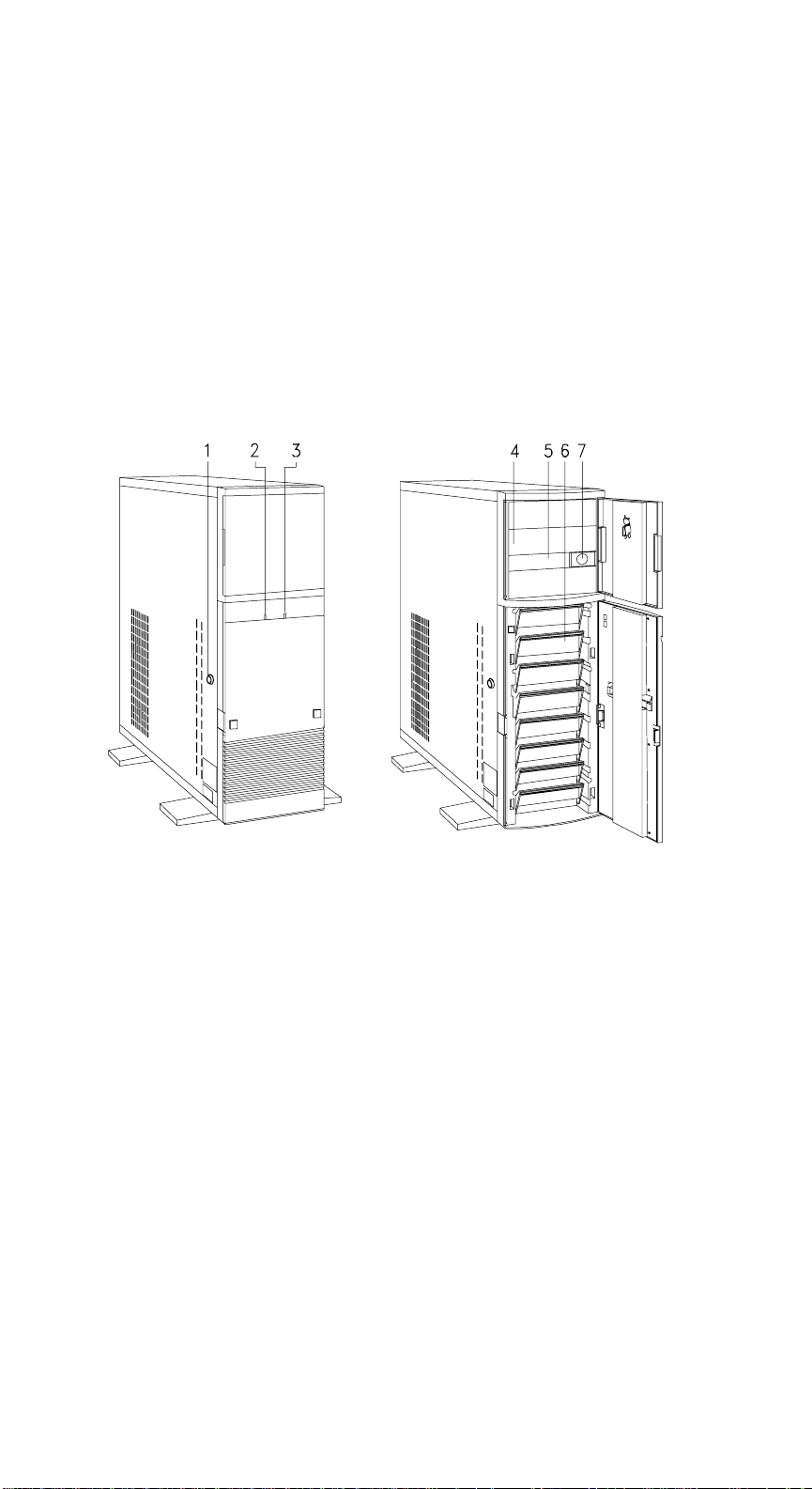
1 Keylock 5 3.5-inch Drive Bay
2 Hard Disk Drive LED 6 Hard Disk Drive Trays
3 Power LED 7 Power Button
4 5.25-inch Drive Bays
Figure 1-1 Front Panel
Chapter 1 - System Housing
1-1
Page 20

Table 1-1 Features and Functions of the Front Panel
Feature Function
Keylock Locks or unlocks the system housing
Hard Disk Drive LED Indicates hard disk drive activity for hard drives
Power LED Indicates that power is applied to the system
3.5-inch Diskette Drive Accommodates a 3.5-inch diskette
Drive Bays Holds the diskette drives and fixed disk drives
Power Button Turns the system on or off
AcerAltos 9000 User’s Guide
1-2
Page 21
1.1.2 Rear Panel
1
2
3
4
5
6
7
8
9
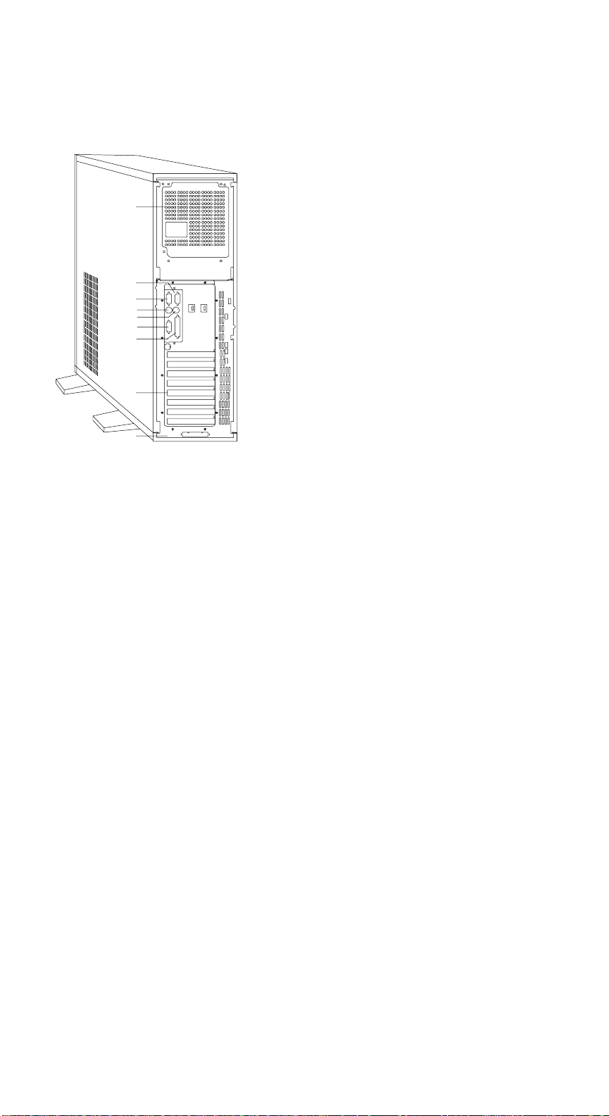
1. Power Supply Fan
2. COM1
3. COM2
4. Keyboard Port
5. Mouse Port
Figure 1-2 Rear Panel
6. Video Port
7. Parallel Port
8. Expansion Slots
9. SCSI Expansion slot
Chapter 1 - System Housing
1-3
Page 22

Table 1-2 Features and Functions of the Rear Panel
Feature Function
Parallel Port Connects a parallel printer
Serial Ports Connects serial peripherals
SCSI Port Connects peripheral devices for high-speed,
parallel data transfer
Expansion Slots For additional expansion boards
Keyboard Connector Connects a PS/2-compatible keyboard
Mouse Connector Connects a PS/2-compatible mouse
AcerAltos 9000 User’s Guide
1-4
Page 23

1.2 Getting Started
The preinstallation process involves the following:
• Selecting a site
• Unpacking the components
• Positioning the system
• Moving the System
1.2.1 Selecting a Site
Consider the following when selecting a site for the system:
1. Find a place that is comfortable for you. Avoid dusty areas of extreme
temperature and humidity.
2. Cable paths should not run near equipment that might cause electromagnetic
or frequency interference such as radio transmitters, television sets, copying
machines, heaters, or air conditioners.
3. Find a location close to an electrical outlet. Avoid using extension cords.
4. Leave enough space around the system for normal air circulation.
Chapter 1 - System Housing
1-5
Page 24

1.2.2 Unpacking the System
Unpack the contents of the system box, following instructions found with the
system unit.
The system box contains the base system with one 3.5-inch diskette drive
installed, onboard video board and an accessory tray. Additional peripherals and
configurations may be installed depending upon model.
The accessory tray contains the following:
• AcerAltos 9000 User's Guide - (this manual)
• Power Cord
• Keyboard and mouse
• Acer StartUp CD software bundle
• Warranty Package
• Mounting hardware for peripherals
AcerAltos 9000 User’s Guide
1-6
Page 25
1.2.3 Positioning the System
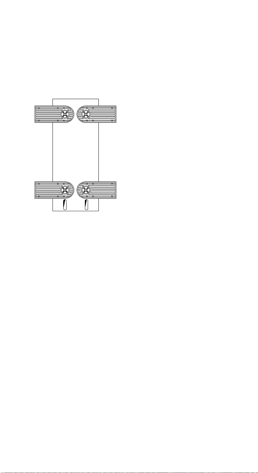
Arrange the legs of the system in such a way that the system is stable. Figure 1-3
shows the correct position of the legs when they are extended.
Figure 1-3 Extending the Chassis Legs (bottom view)
Chapter 1 - System Housing
1-7
Page 26
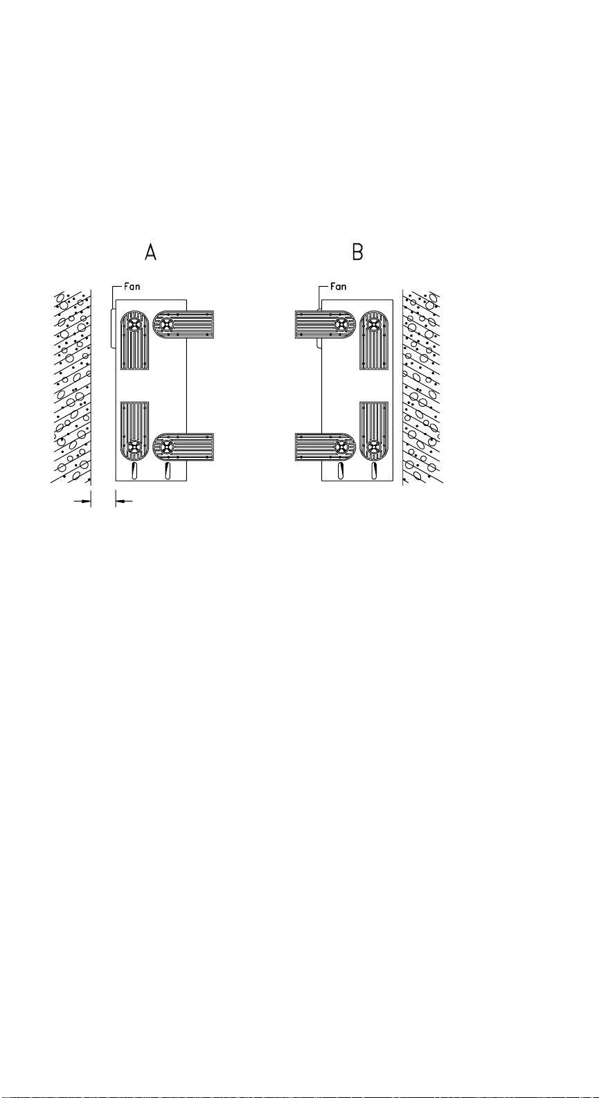
When placing the system with side fan facing a wall, leave a space of 2 - 4 inches
from the wall to allow air circulation, then position the legs as in Detail A in
Figure 1-4.
When standing the system with side fan facing out, place the system close to the
wall and position the legs as in Detail B in Figure 1-4.
2 - 4 inches
Figure 1-4 Placing the System Near a Wall
AcerAltos 9000 User’s Guide
1-8
Page 27
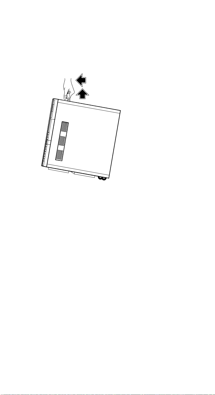
1.2.4 Moving the System
The system housing has a handle on top and two wheels at the base to move it
easily. Figure 1-5 shows how to move the system.
Figure 1-5 Moving the System
NOTE: Be sure to re-position the legs underneath the system before moving.
Chapter 1 - System Housing
1-9
Page 28
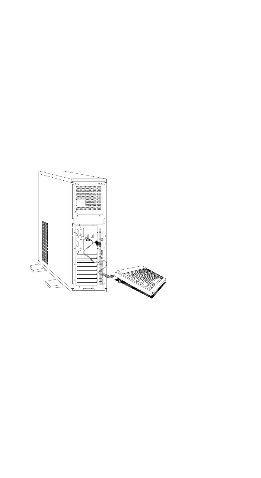
1.3 Connecting Components
CAUTION: Make sure that the system is turned off before connecting any
system components.
NOTE: Each component plug is keyed allowing it to be inserted in one
direction.
Follow these steps to connect the component:
1. Plug the keyboard into the keyboard socket.
Figure 1-6 Connecting the Keyboard
AcerAltos 9000 User’s Guide
1-10
Page 29
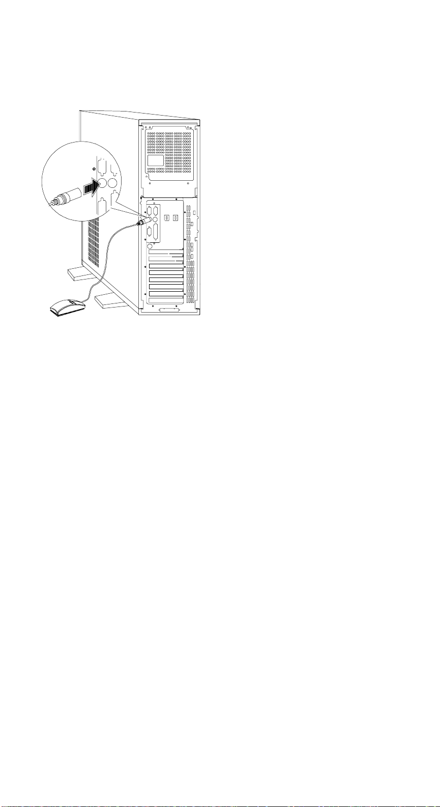
2. Connect the mouse into the mouse connector.
Figure 1-7 Connecting the Mouse
Chapter 1 - System Housing
1-11
Page 30
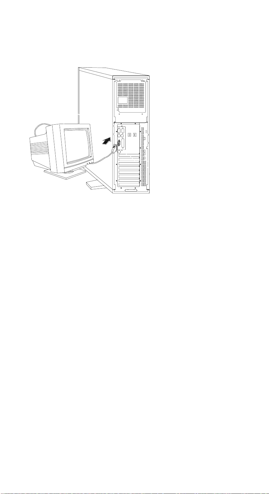
3. Connect the monitor cable into the video socket.
Figure 1-8 Connecting a Monitor
AcerAltos 9000 User’s Guide
1-12
Page 31
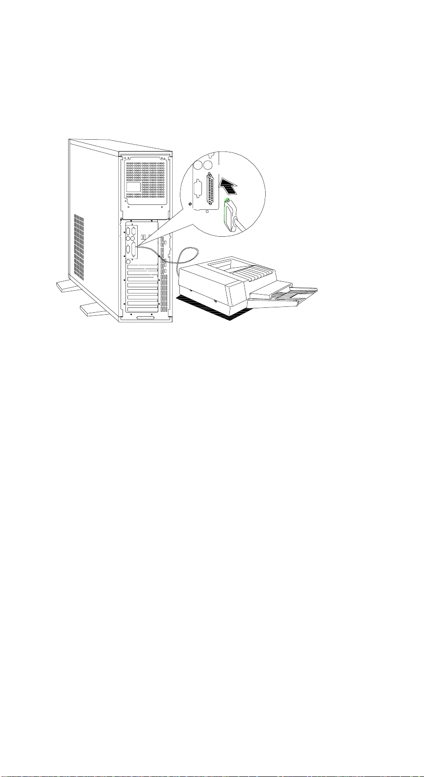
4. If you have a parallel printer, connect it to the parallel port.
If you have a serial printer or other serial peripherals, connect it to a serial
port (Serial 1 or Serial 2). Refer to Figure 2-1 for serial port locations.
Figure 1-9 Connecting a Printer
Chapter 1 - System Housing
1-13
Page 32
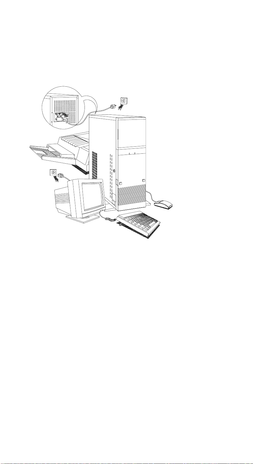
5. Plug the female end of the power connector into the system power socket and
the other end into a grounded electrical outlet.
6. Plug the monitor power cable into a grounded electrical outlet.
Figure 1-10 Complete System Connections
AcerAltos 9000 User’s Guide
1-14
Page 33

1.4 Installing Options
This section tells you how to open the system housing and install additional
components in the system.
1.4.1 ESD Precautions
Integrated circuits (ICs) on expansion boards are sensitive to static electricity. To
avoid damaging the chips from electrostatic discharge (ESD), observe the
following precautions:
1. Do not remove a board from its packaging until you are ready to install it.
2. Wear a wrist grounding strap before handling electronic components. Wrist
grounding straps are available at most electronic component stores.
Chapter 1 - System Housing
1-15
Page 34
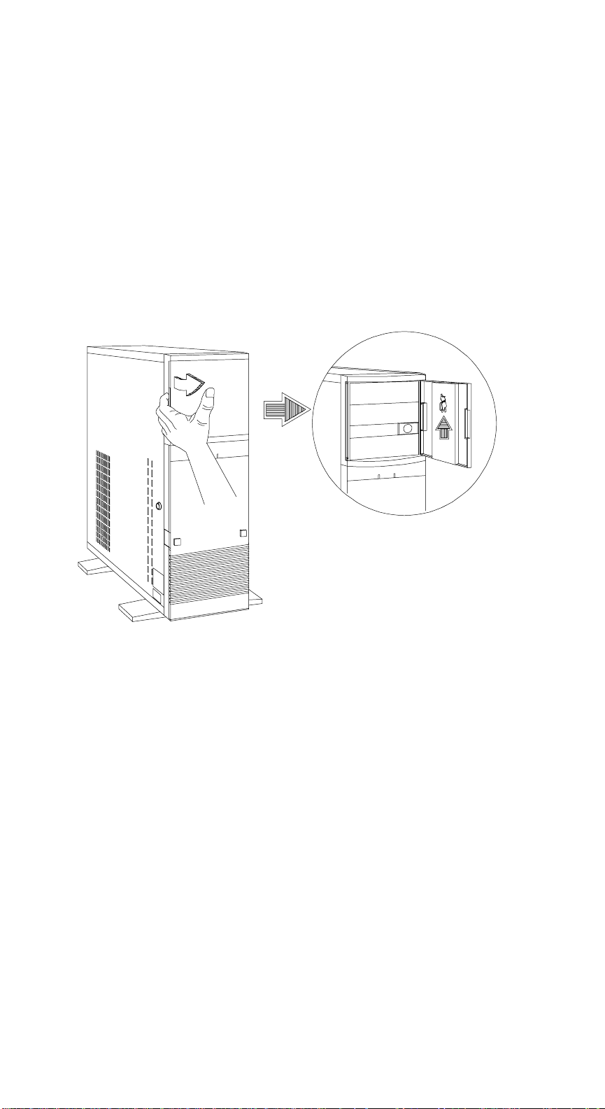
1.5 Opening the System
CAUTION! Turn OFF the system and unplug the power cable from the wall
socket before opening the system.
1.5.1 Opening the Housing Panels
1.5.1.1 Upper Front Panel
Hold either the right or left edge of the upper front panel to open it and gain
access to the CD-ROM and 1.44 MB diskette drives. The housing keys are inside
the front panel.
AcerAltos 9000 User’s Guide
1-16
Page 35
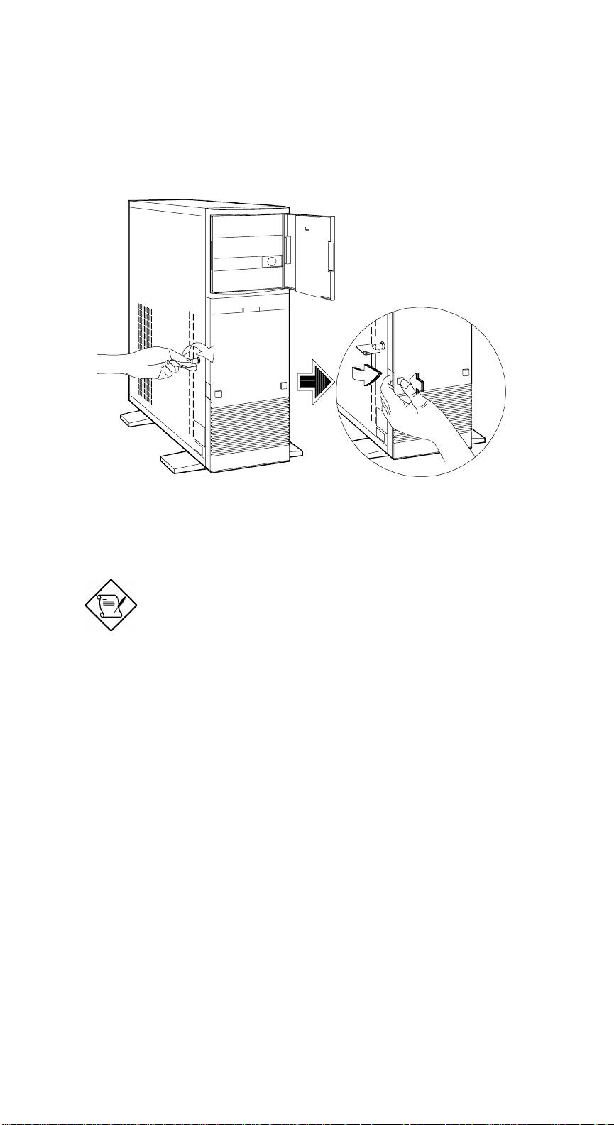
1.5.1.2 Lower Front Panel
Unlock the housing with the key. Press either the left or right button then pull the
panel to access the drive trays.
You cannot remove the key after you have
unlocked the housing. You can remove it
only when you lock the housing again.
Chapter 1 - System Housing
1-17
Page 36
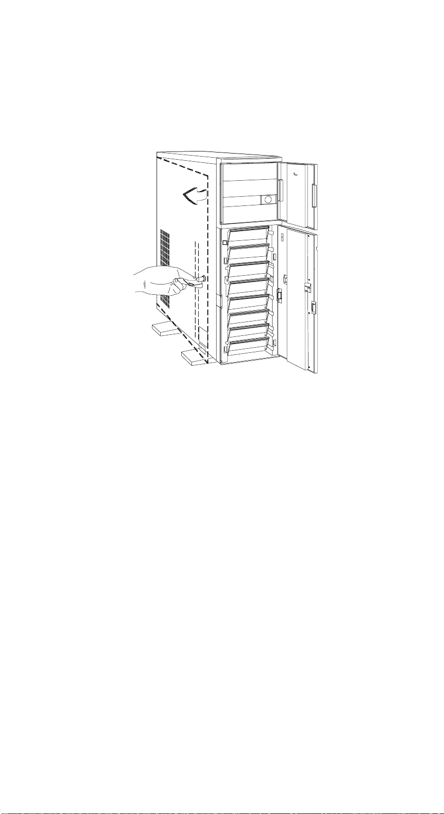
1.5.1.3 Left Panel
Pull on the key to swing the left panel open. If necessary, you may use a
screwdriver to pry open the panel.
AcerAltos 9000 User’s Guide
1-18
Page 37
1.5.2 Installing Disk Drives
Turn off the power switch and unplug the
power cord before installing or removing
drives, unless you are utilizing a RAID
controller and drives that support hot
swapping.
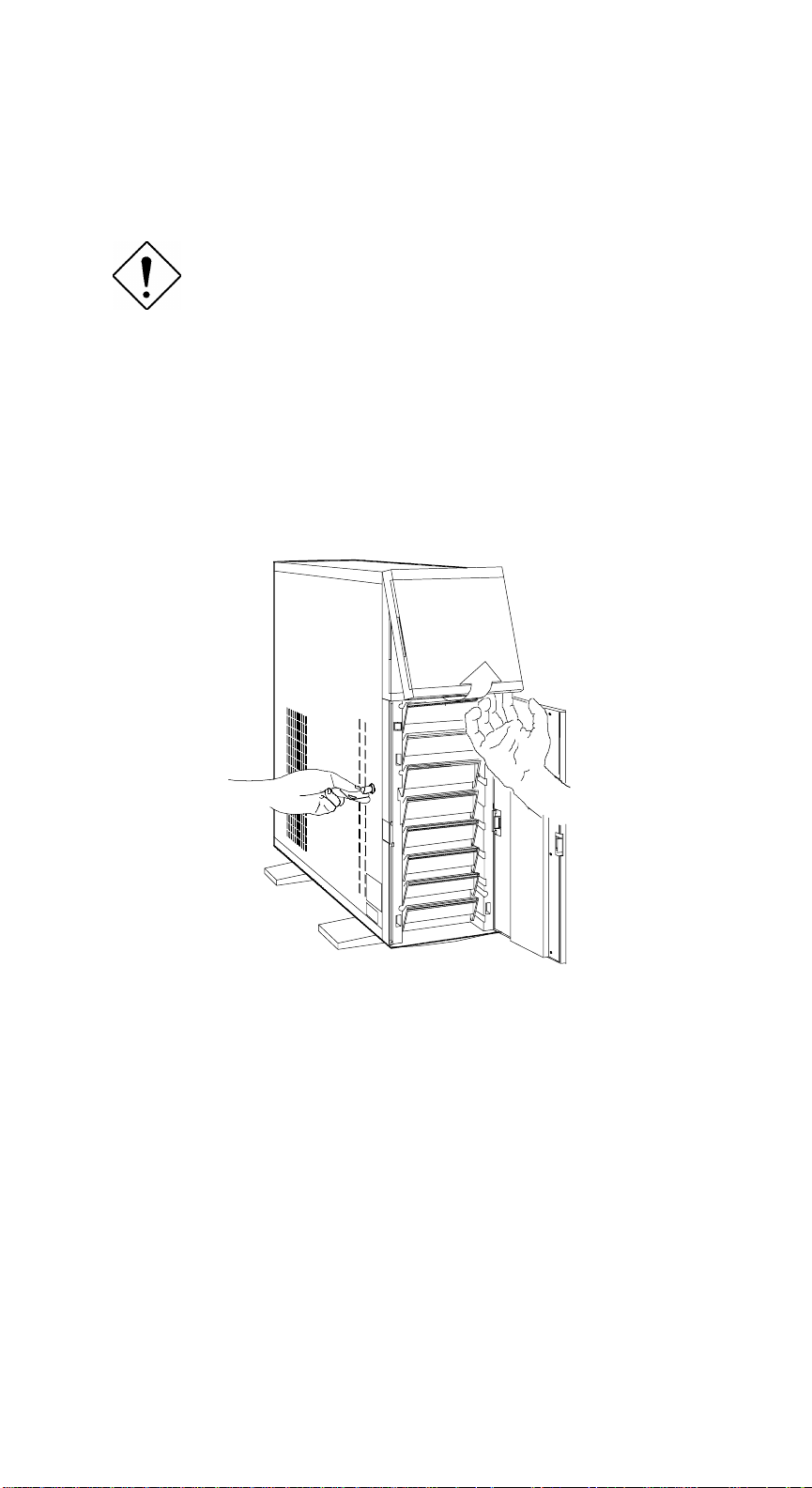
1.5.2.1 3.5-inch Diskette Drive
1. Open the lower front panel.
2. Remove the upper panel including its frame by pressing the latch underside
and pulling the panel out.
Chapter 1 - System Housing
1-19
Page 38
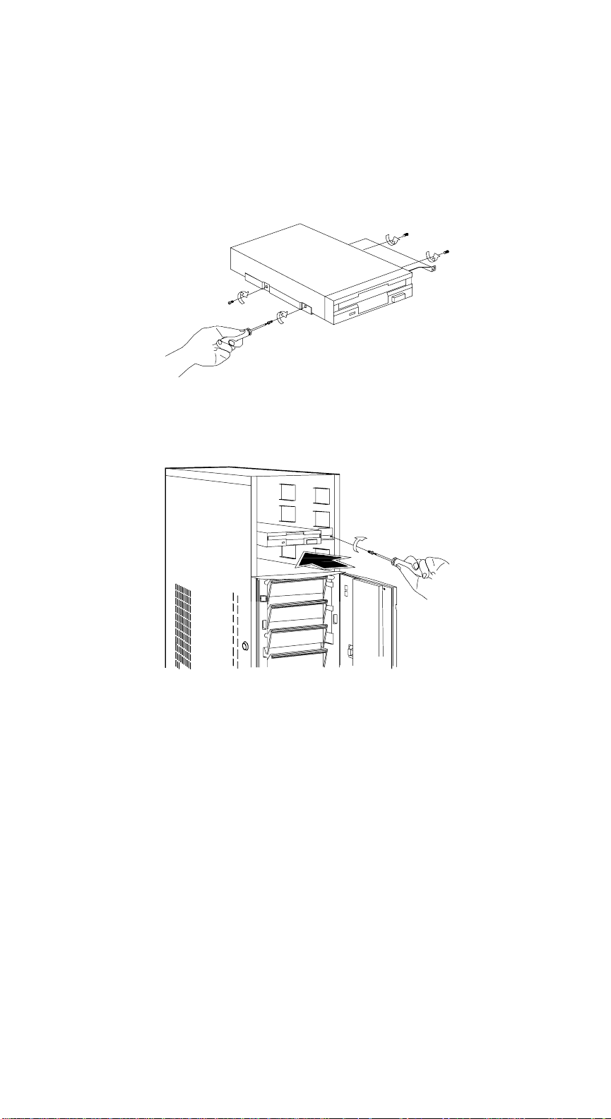
3. Remove the screw attaching the 3.5-inch drive frame to the housing.
4. Secure a 3.5-inch drive on the frame with four screws.
5. Insert the drive into the drive bay and secure it with a screw.
6. Connect the diskette drive cables.
AcerAltos 9000 User’s Guide
1-20
Page 39
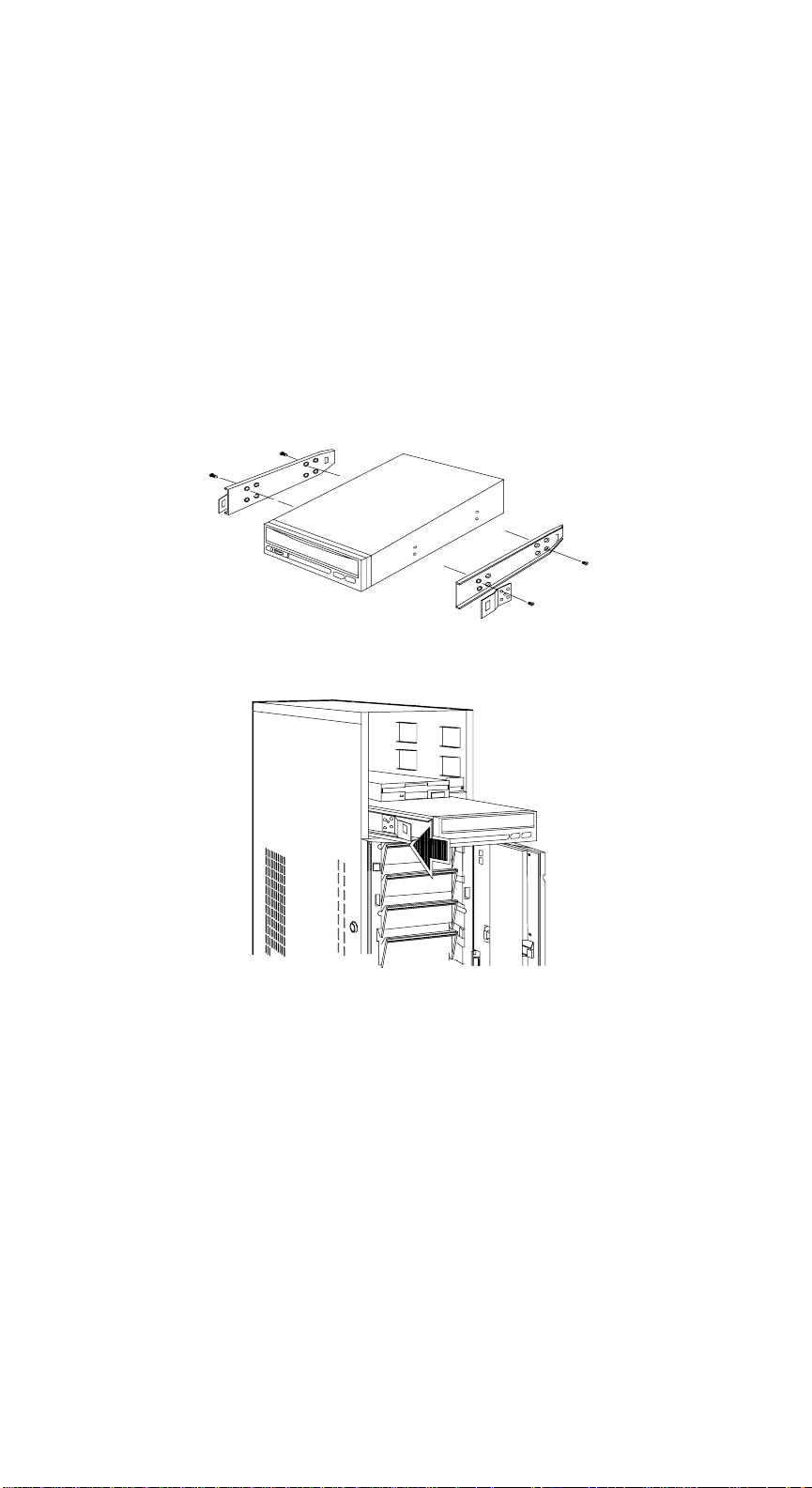
1.5.2.2 5.25-inch Drive
You may install a CD-ROM, QIC tape, hard disk, diskette drive or any other 5.25inch form factor device into the drive bay(s).
1. Open the lower front panel.
2. Remove the upper panel including its frame by pressing the latch underside
and pulling the panel out.
3. Secure the drive guides on the sides of a 5.25-inch drive.
4. Insert the drive into the drive bay.
5. Connect the signal and power cables to the drive.
Chapter 1 - System Housing
1-21
Page 40
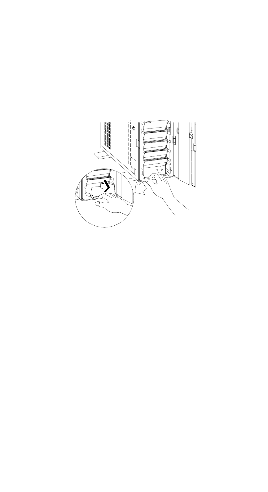
1.5.2.3 3.5-inch Hard Disk
1. Slide the power switch of the drive tray to the Unlock/Power Off position.
2. Pull down the tray handle and remove the tray.
AcerAltos 9000 User’s Guide
1-22
Page 41
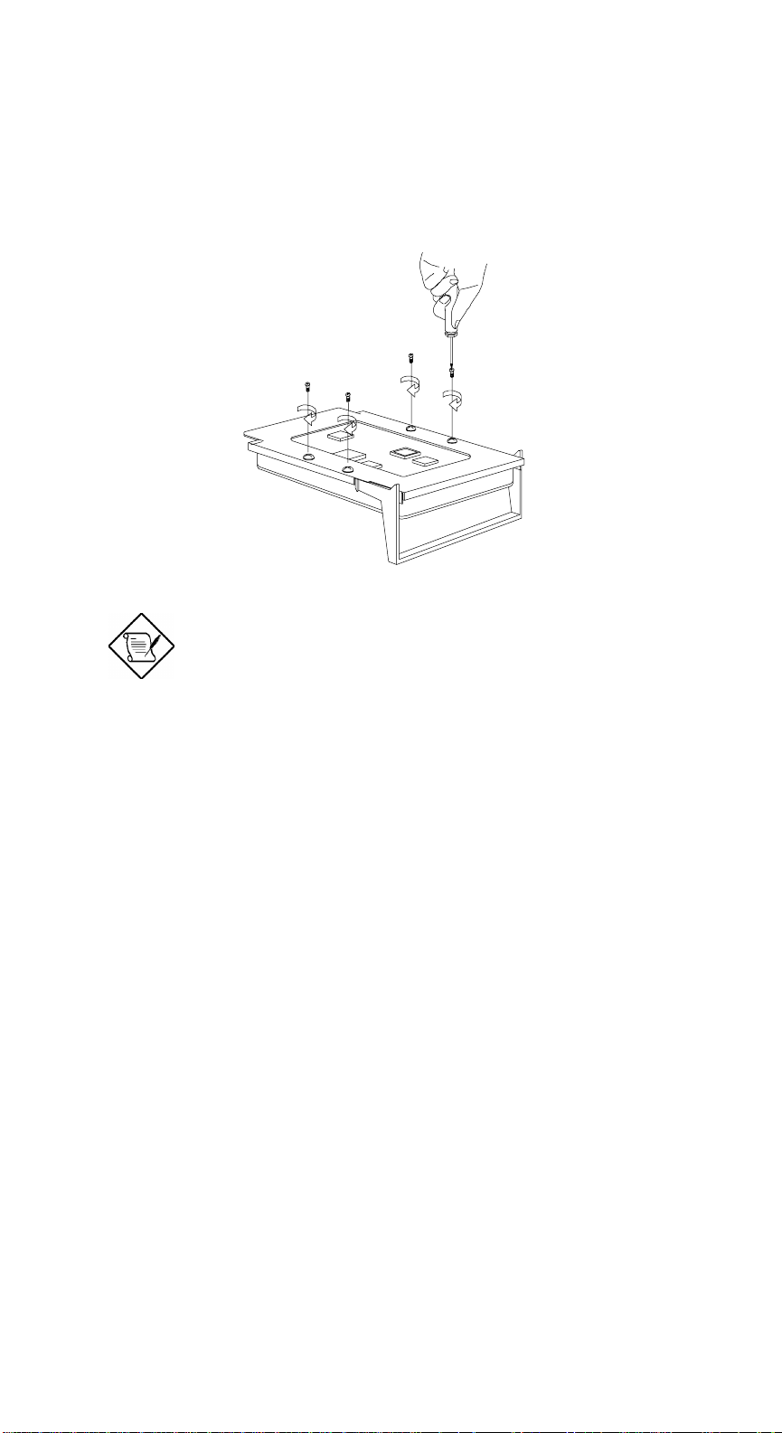
3. Place a hard disk on the tray and secure it with four screws. Refer to
Appendix B for information about connecting the drive cables.
Only fast/wide SCSI drives can be used;
fast/narrow SCSI drives will not fit or work in
the AcerAltos 9000 drive tray.
Chapter 1 - System Housing
1-23
Page 42
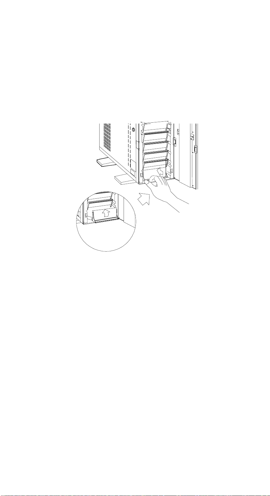
4. Insert the tray back into the housing.
5. Slide the power switch of the drive tray to the Lock/Power On position.
AcerAltos 9000 User’s Guide
1-24
Page 43
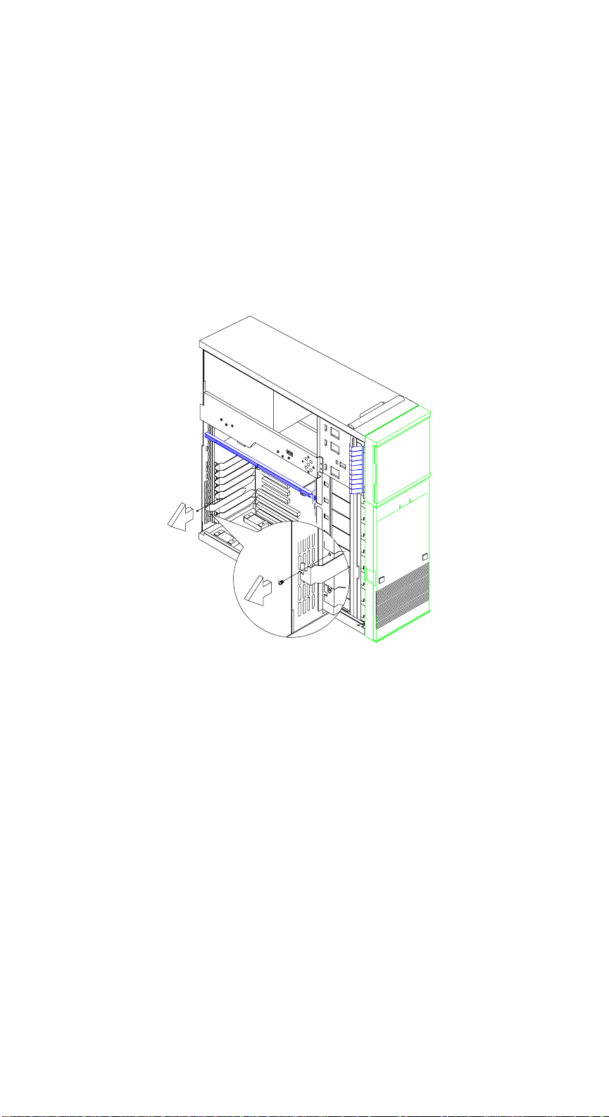
1.5.3 Installing An Expansion Board
1. Remove an expansion slot bracket cover. Save the screw to secure the
expansion board.
Chapter 1 - System Housing
1-25
Page 44
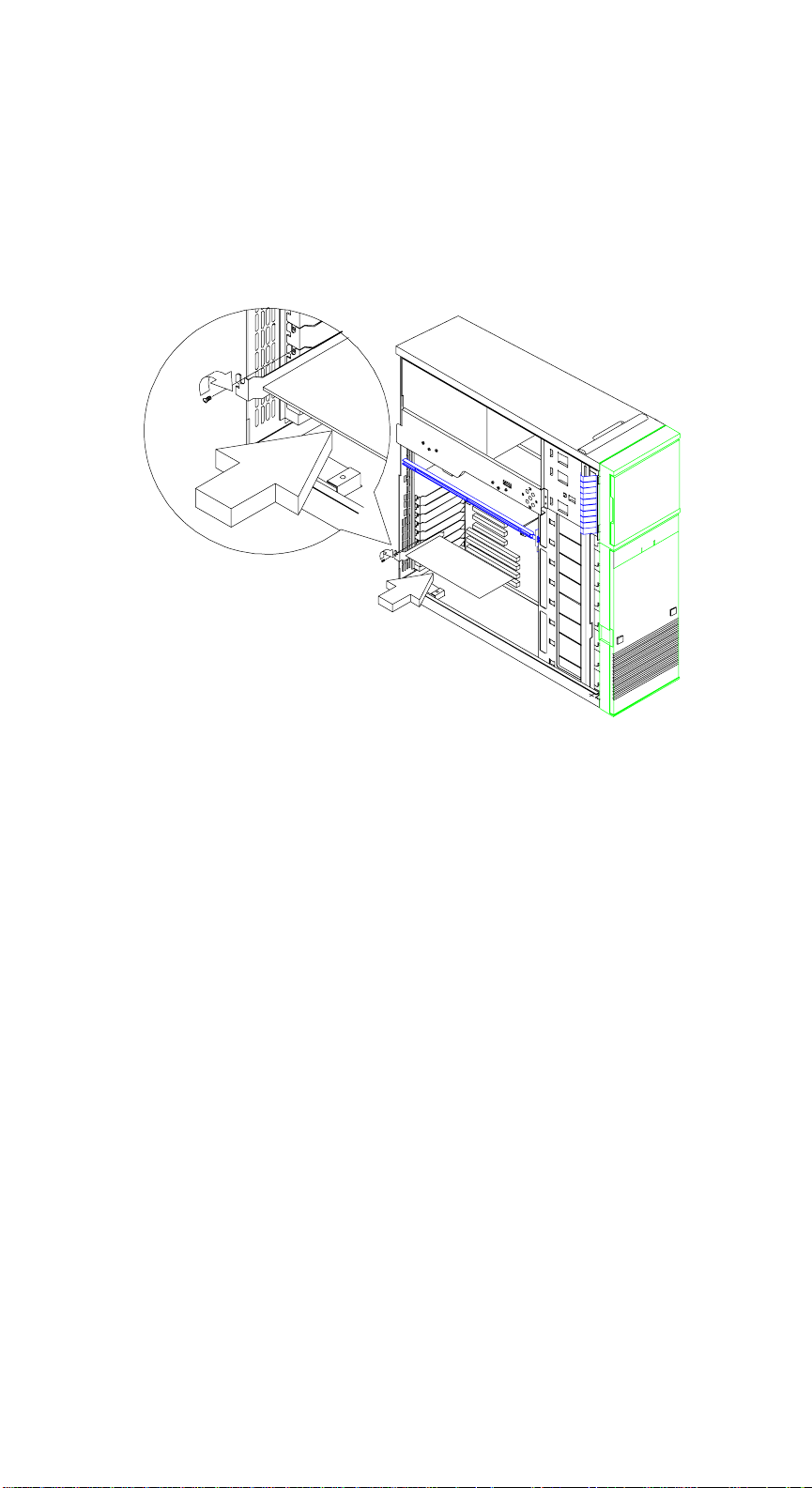
2. Align an expansion board with the open slot and insert the golden fingers
into the expansion bus connector.
3. Secure the board with a screw.
AcerAltos 9000 User’s Guide
1-26
Page 45
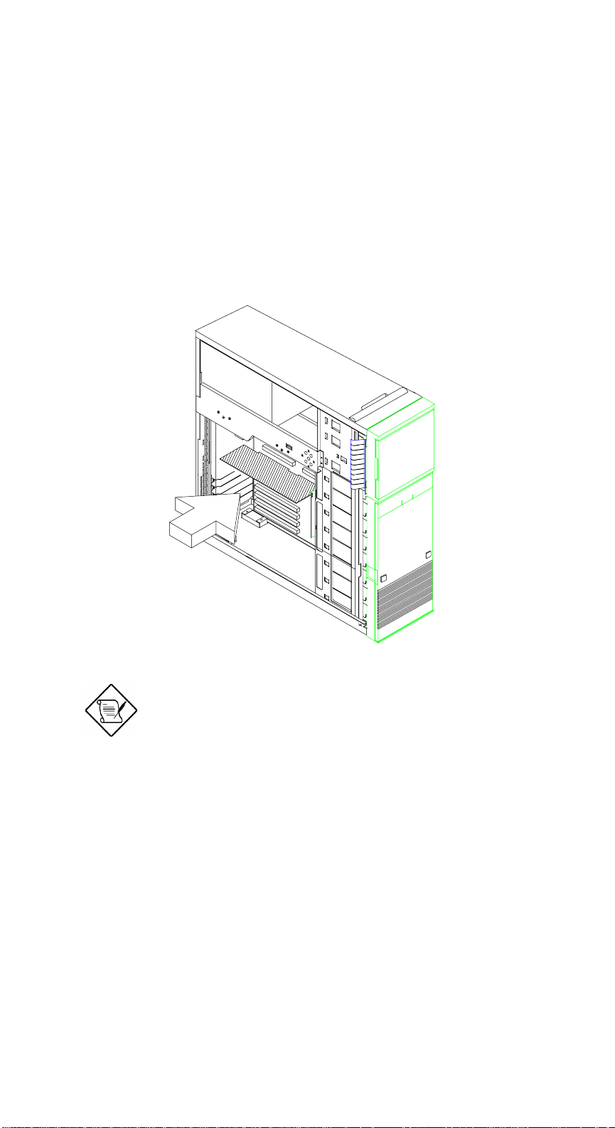
1.5.4 Installing a CPU Board
Follow these steps to re-install the CPU board after reconfiguring or adding an
additional CPU.
1. Remove the support board bar, if installed.
2. Insert the board into the slot.
Make sure that the board is properly seated
in the slot.
3. Re-insert the support board bar.
Chapter 1 - System Housing
1-27
Page 46
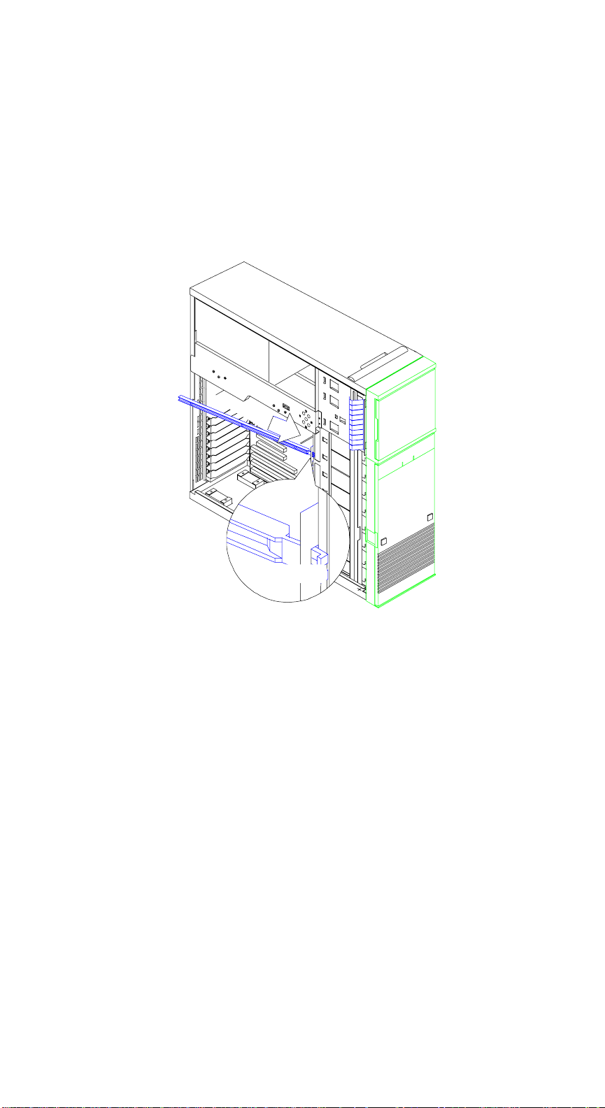
4. Align the plastic support bar with the board edge.
5. Insert the right end of the bar to the hole near the hard disk drive frame and
the left end to the hole on the rear panel.
Left End
AcerAltos 9000 User’s Guide
1-28
Right End
Page 47

1.6 Drive Tray Management System (DTMS)
Hot Plug Backplane
The BP-W8 wide SCSI backplane subsystem consists of a backplane board and
drive trays that support wide SCSI hard disk drives. The BP-W8 backplane is
specifically designed for a tower housing that accommodates up to eight SCSI
drives.
The backplane subsystem major features are listed below:
• “Hot-swap” feature that allows replacement of a defective hard drive even
while the system is in full operation. This feature requires a RAID controller
board and RAID drivers.
• Two LEDs on the SCSI drive tray front panel to indicate power and drive
failure
• Allows “split” and “combine” SCSI-channel configurations
• SCSI ID strapping that allows wide SCSI HDD ID configuration through the
backplane switches instead of configuring the individual drive IDs
• Fixed 2.85-volt termination
The DTMS hot-plug backplane is discussed in detail in Appendix B. Refer to
Appendix B for information about:
• Major components
• Jumper settings
• Hard disk ID setting options
• SCSI channel configurations (single and dual channel)
• How to install a SCSI hard disk
• How to use the hot-plug feature
Chapter 1 - System Housing
1-29
Page 48

AcerAltos 9000 User’s Guide
1-30
Page 49

Chapter 2 System Board
2.1 Features
The AcerAltos 9000 is a dual-processor capable system that supports the Intel
Pentium processor. The system board contains an exclusive slot for the CPU
board that carries two 321-pin zero-insertion force (ZIP) CPU sockets plus an
embedded 512 KB pipeline burst second-level cache.
This high-performance 64-bit system board utilizes both EISA and PCI local bus
architecture. Two EISA, four PCI bus slots, and one EISA/PCI shared slot reside
on the board to allow installation of either master or slave devices.
The system board has four DRAM banks composed of eight 72-pin SIMM sockets
that accommodate both fast-page mode and EDO (extended data output) SIMMs.
The sockets support a total of 256-MB system memory using 32-MB SIMMs.
A 50-pin Fast SCSI interface and a 68-pin Wide SCSI interface come with the
system board to connect SCSI devices. Standard external I/O interfaces include
two 9-pin serial ports, one parallel port, a video port, and keyboard and mouse
ports.
Chapter 2 - System Board
2-1
Page 50

2.2 Major Components
The system board has the following major components:
• Four DRAM banks composed of eight 72-pin SIMM sockets that support
single- and double-density 60/70ns SIMMs
• CPU board slot
• Four PCI and two EISA bus slots, and one EISA/PCI shared slot
• 256 KB Flash ROM for system BIOS
• System clock/calendar plus 8 KB extended CMOS RAM with battery backup
• 50-pin Fast SCSI and 68-pin Wide SCSI interfaces
• Two 24-pin RDM interfaces
• Onboard VRAM and VRAM sockets for video memory upgrade
• Power connector for 350-watt switching power supply (115/230V)
• Super I/O, SCSI, VGA, memory, and Advanced Server Management (ASM)
controller chipsets
• External ports:
• Two 9-pin serial ports
• PS/2-compatible keyboard port
• PS/2-compatible mouse port
• Parallel port
• Video port
AcerAltos 9000 User’s Guide
2-2
Page 51
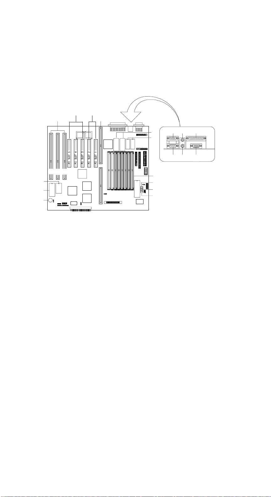
2.3 Layout
5
13
5
Figure 2-1 shows the locations of system board components.
2
1
3
4
E3 E2 E1
17
18
19
1 EISA slots
2 PCI slots (secondary)
3 PCI slots (primary)
4 CPU board slot
5 COM1
6 Mouse port
7 Parallel port
8 COM2
9 Keyboard port
Figure 2-1 System Board Layout
11
12
8
14
1
16
10 Video port
11 Video upgrade sockets
12 Video RAM
13 SIMM sockets
14 Fan connector 3 (FA3)
15 Fan connector 2 (FA2)
16 Fan connector 1 (FA1)
17 Buzzer
18 Flash ROM BIOS
19 Real-time clock
6 7
10
Chapter 2 - System Board
2-3
Page 52
2.4 Jumpers and Connectors
2.4.1 Jumper and Connector Locations
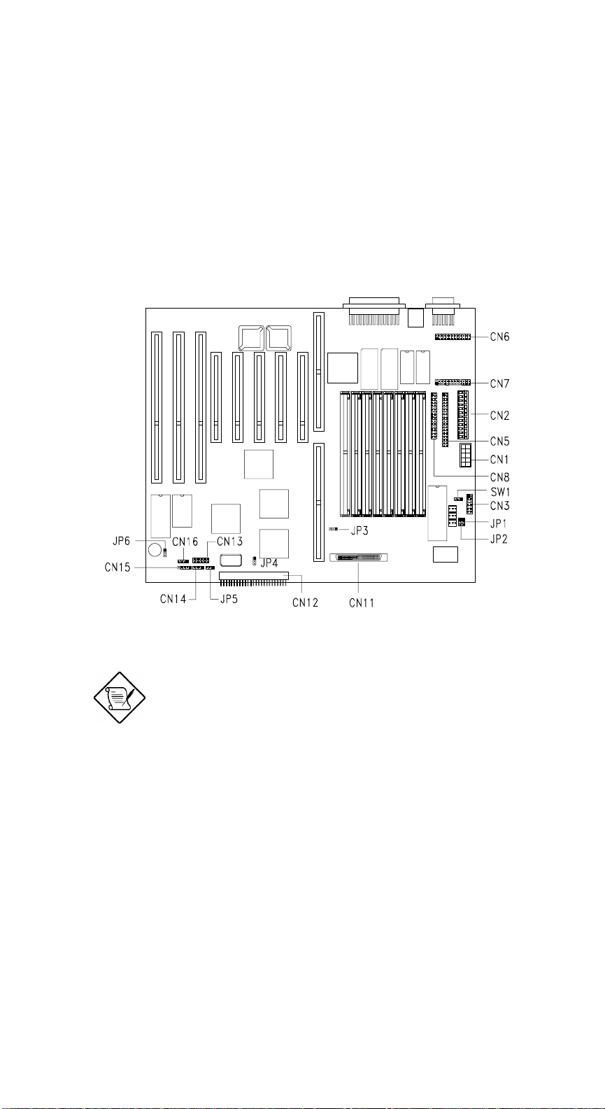
Figure 2-2 shows the jumper and connector locations on the system board.
Figure 2-2 System Board Jumper and Connector Locations
Jumpers are prefixed “JP”. Connectors are
prefixed “CN” and “SW.
On this figure, the blackened pin of a jumper
represents pin 1.
AcerAltos 9000 User’s Guide
2-4
Page 53
2.4.2 Jumper Settings
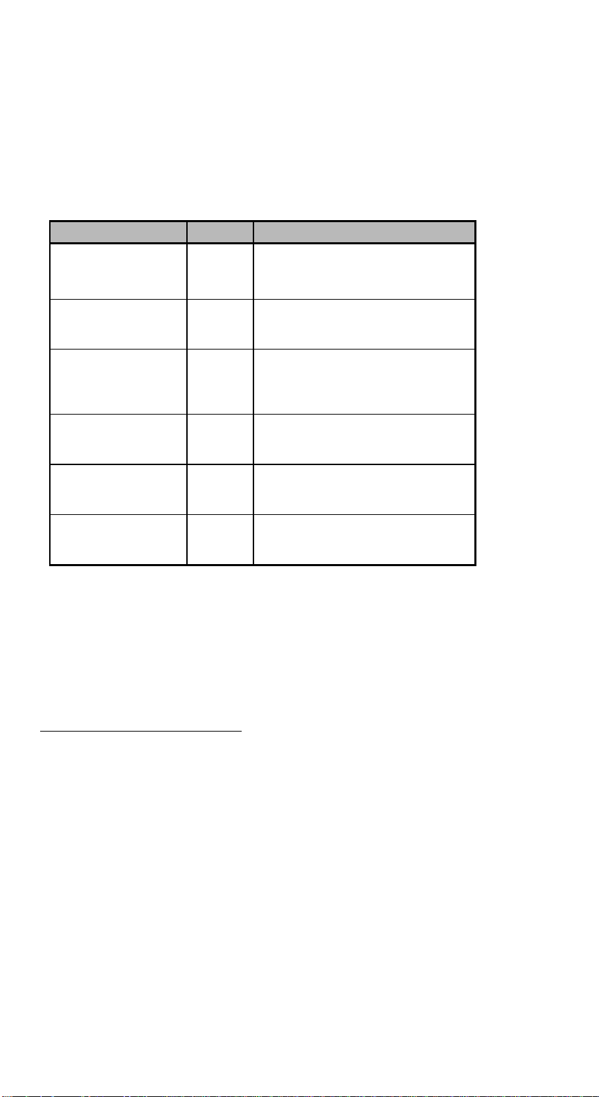
Table 2-1 lists the system board jumpers with their corresponding settings and
functions.
Table 2-1 System Board Jumper Settings
Jumper Setting Function
Password Security
JP1 1-2
BIOS Type
JP2 1-2*
SCSI Termination
JP3 1-2
SCSI Feature
JP4 1-2*
Hardware Reset
JP5 1-2
Sound Feature
JP6 1-2*
2-3
2-3
2-3*
2-3
2-3*
2-3
*
Check password
Bypass password
Acer
OEM
Terminator always set to ON
Use SCSI Setup Utility to set
terminator to ON or OFF
Wide SCSI
Standard
Enabled
Disabled
Buzzer
Speaker
* Default setting
Chapter 2 - System Board
2-5
Page 54
2.4.3 Connector Functions
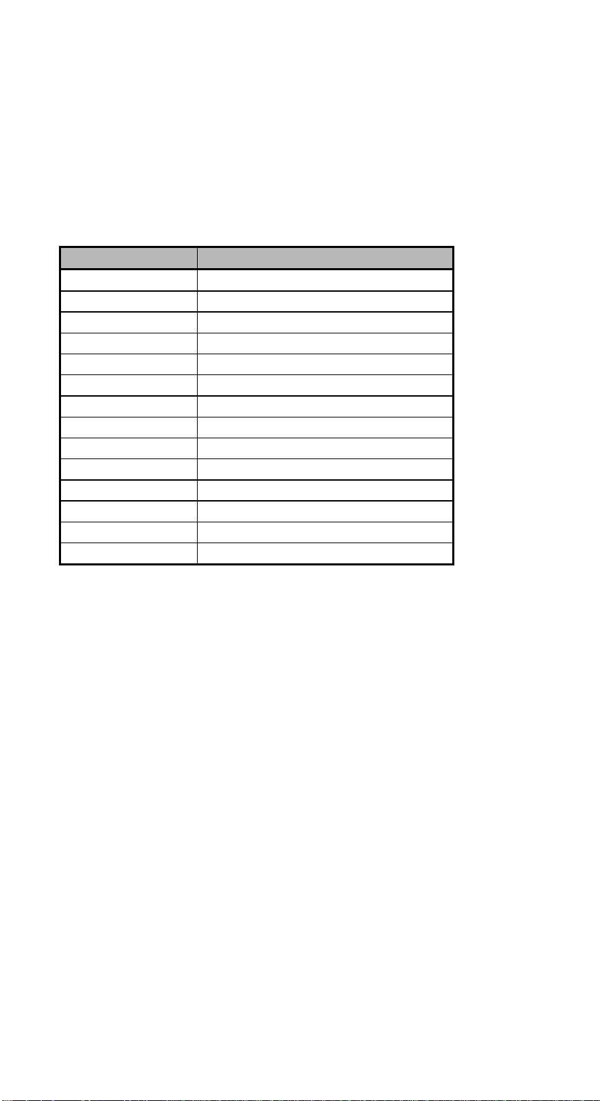
Table 2-2 lists the different connectors on the system board and their respective
functions.
Table 2-2 Connector Functions
Connector Function
CN1 Power connector
CN2 Power connector
CN3 Backplane board HDD status connector
CN5 IDE hard disk connector
CN6 RDM connector
CN7 RDM connector
CN8 Diskette drive connector
CN11 68-pin Wide SCSI connector
CN12 50-pin Fast SCSI connector
CN13 LED board connector
CN14 Hard disk LED connector
CN15 Power LED connector
CN16 Speaker connector
SW1 NMI switch
AcerAltos 9000 User’s Guide
2-6
Page 55

2.5 ESD Precautions
Always observe the following electrostatic discharge (ESD) precautions before
installing a system component:
1. Do not remove a component from its antistatic packaging until you are ready
to install it.
2. Wear a wrist grounding strap before handling electronic components. Wrist
grounding straps are available at most electronic component stores.
Do not attempt the procedures described in
the following sections unless you are a
qualified technician.
2.6 Memory Upgrade
The system board comes with eight 72-pin SIMM sockets that support 4-MB and
16-MB single-density SIMMs as well as 8-MB and 32-MB double-density SIMMs
for a total system memory of 256-MB. The sockets support both the fast page
mode and EDO 60/70 ns SIMMs.
See Table 2-3 for a list of some possible memory configurations.
2.6.1 Rules for Adding Memory
• Use only one type of SIMM in a given bank. You may combine different
types of SIMMs for a memory configuration as long as the SIMMs in each
bank are of the same type.
• You may use the memory banks (Bank0 ~ Bank3) in any order.
• Always install SIMMs in pairs. For example, for a total memory of 16 MB,
install two 8-MB SIMMs in a bank. You can not use a 16-MB SIMM alone for
a 16-MB memory.
• Run the EISA Configuration Utility (ECU) after changing memory capacity.
Chapter 2 - System Board
2-7
Page 56
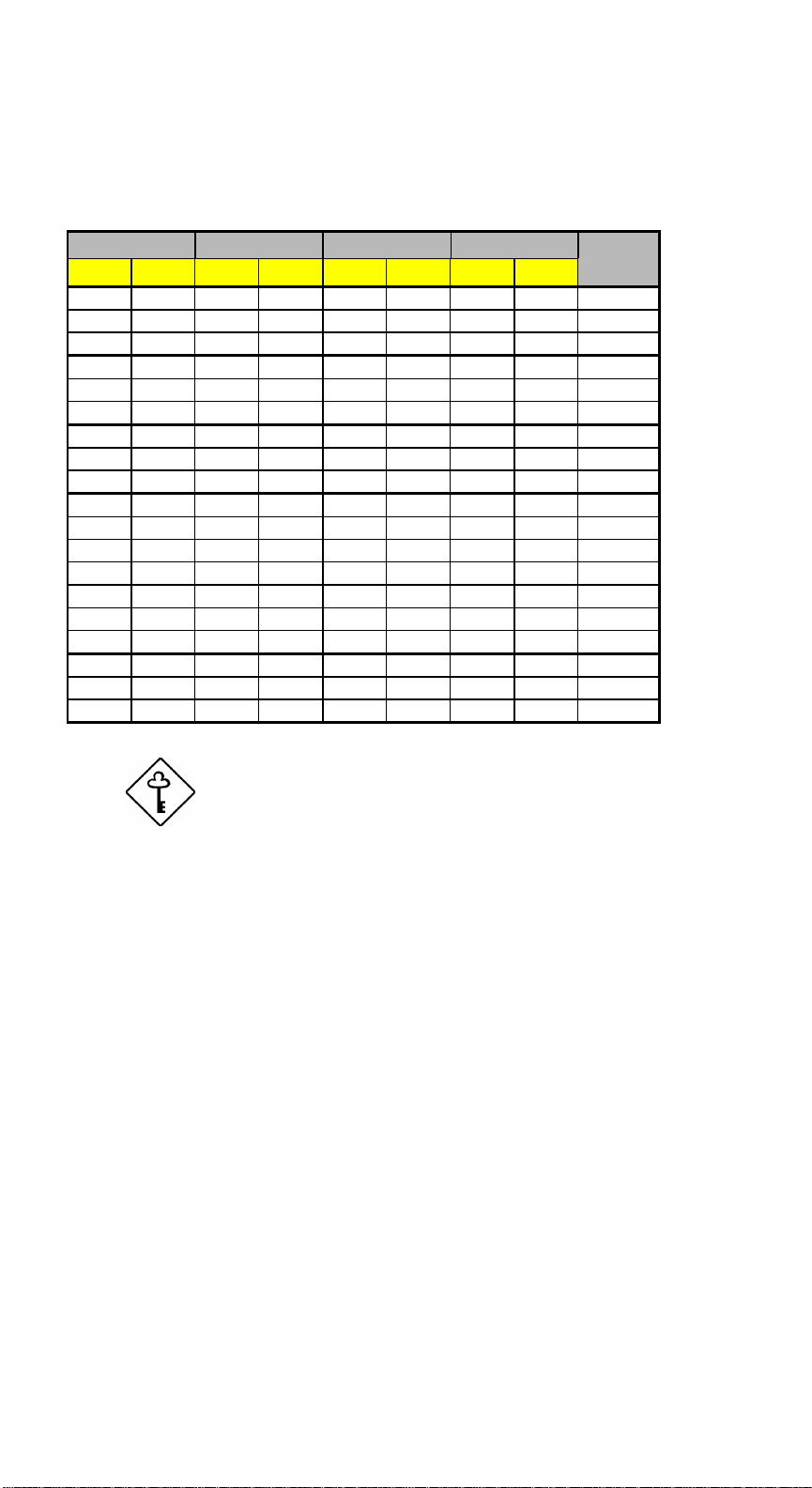
2.6.2 Memory Configurations
Table 2-3 Memory Configurations
Bank0 Bank1 Bank2 Bank3 Total
S1 S2 S3 S4 S5 S6 S7 S8 Memory
8 MB 8 MB 16 MB
16 MB 16 MB 32 MB
32 MB 32 MB 64 MB
8 MB 8 MB 8 MB 8 MB 32 MB
16 MB 16 MB 16 MB 16 MB 64 MB
32 MB 32 MB 32 MB 32 MB 128 MB
8 MB 8 MB 16 MB 16 MB 48 MB
8 MB 8 MB 32 MB 32 MB 80 MB
16 MB 16 MB 32 MB 32 MB 96 MB
8 MB 8 MB 16 MB 16 MB 48 MB
8 MB 8 MB 16 MB 16 MB 16 MB 16 MB 80 MB
8 MB 8 MB 16 MB 16 MB 32 MB 32 MB 112 MB
8 MB 8 MB 16 MB 16 MB 32 MB 32 MB 32 MB 32 MB 176 MB
8 MB 8 MB 8 MB 8 MB 16 MB 16 MB 16 MB 16 MB 96 MB
8 MB 8 MB 8 MB 8 MB 32 MB 32 MB 32 MB 32 MB 160 MB
16 MB 16 MB 16 MB 16 MB 32 MB 32 MB 32 MB 32 MB 192 MB
8 MB 8 MB 8 MB 8 MB 8 MB 8 MB 8 MB 8 MB 64 MB
16 MB 16 MB 16 MB 16 MB 16 MB 16 MB 16 MB 16 MB 128 MB
32 MB 32 MB 32 MB 32 MB 32 MB 32 MB 32 MB 32 MB 256 MB
The above configurations are only some of
the available memory combinations. You
can use other combinations as long as you
follow the rules for upgrading memory in
section 2.6.1.
AcerAltos 9000 User’s Guide
2-8
Page 57
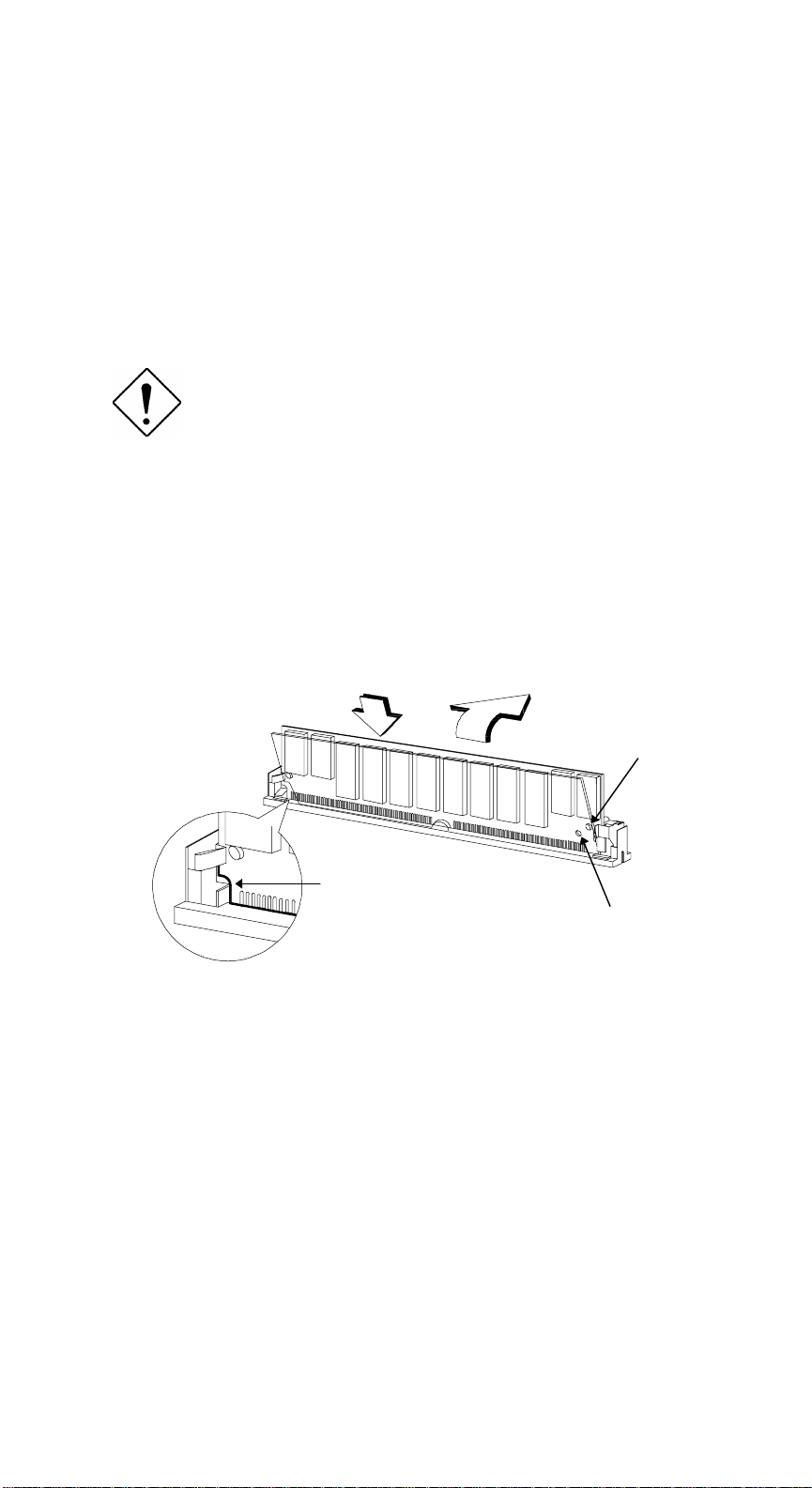
2.6.3 Installing a SIMM
Follow these steps to install a SIMM:
1. Carefully slip a SIMM at a 45
edge indicating the pin 1 of the SIMM matches pin 1 of the socket.
A SIMM fits only in one direction. If you slip
in a SIMM that does not completely fit, you
may have inserted it the wrong way.
Reverse the orientation of the SIMM.
2. Gently push the SIMM to a vertical position until the pegs of the socket slip
into the holes on the SIMM, and the holding clips lock the SIMM into
position. The SIMM should be at a 90
° angle into a socket making sure that the curved
°
angle when installed.
1
2
Peg
Figure 2-3 Installing a SIMM
Pin 1 Indicator
(curved edge)
Hole
Chapter 2 - System Board
2-9
Page 58
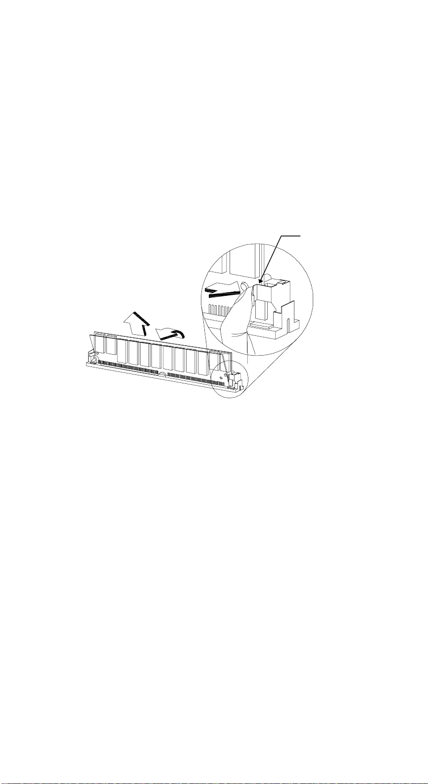
2.6.4 Removing a SIMM
Follow these steps to remove a SIMM:
1. Press the holding clips on both sides of the SIMM outward to release it.
2. Move the SIMM to a 45
3. Pull the SIMM out of the socket.
° angle.
1
3
2
Figure 2-4 Removing a SIMM
Holding Clip
AcerAltos 9000 User’s Guide
2-10
Page 59
2.6.5 Reconfiguring the System
You must enter Setup after installing or removing SIMMs to reconfigure the
system.
Follow these steps to reconfigure the system:
1. Turn the system on. A memory error message appears, indicating that the
total memory does not match the value stored in CMOS.
2. Press
indicating an incorrect memory configuration.
3. Press
The system boots with the new memory configuration.
5. Run the EISA Configuration Utility (ECU).
+ + to enter Setup. A warning message appears
twice to exit and reboot the system.
If you run Windows NT, NetWare, or
UnixWare in the system, make sure to run
the ECU every time you change the memory
size. See Chapter 5 for information on the
ECU.
Chapter 2 - System Board
2-11
Page 60
2.7 Video Memory Upgrade
Larger video memory allows you to display higher resolutions and more colors.
The system board comes with a 1-MB video memory onboard upgradable to
2 MB.
Follow these steps to upgrade the video memory:
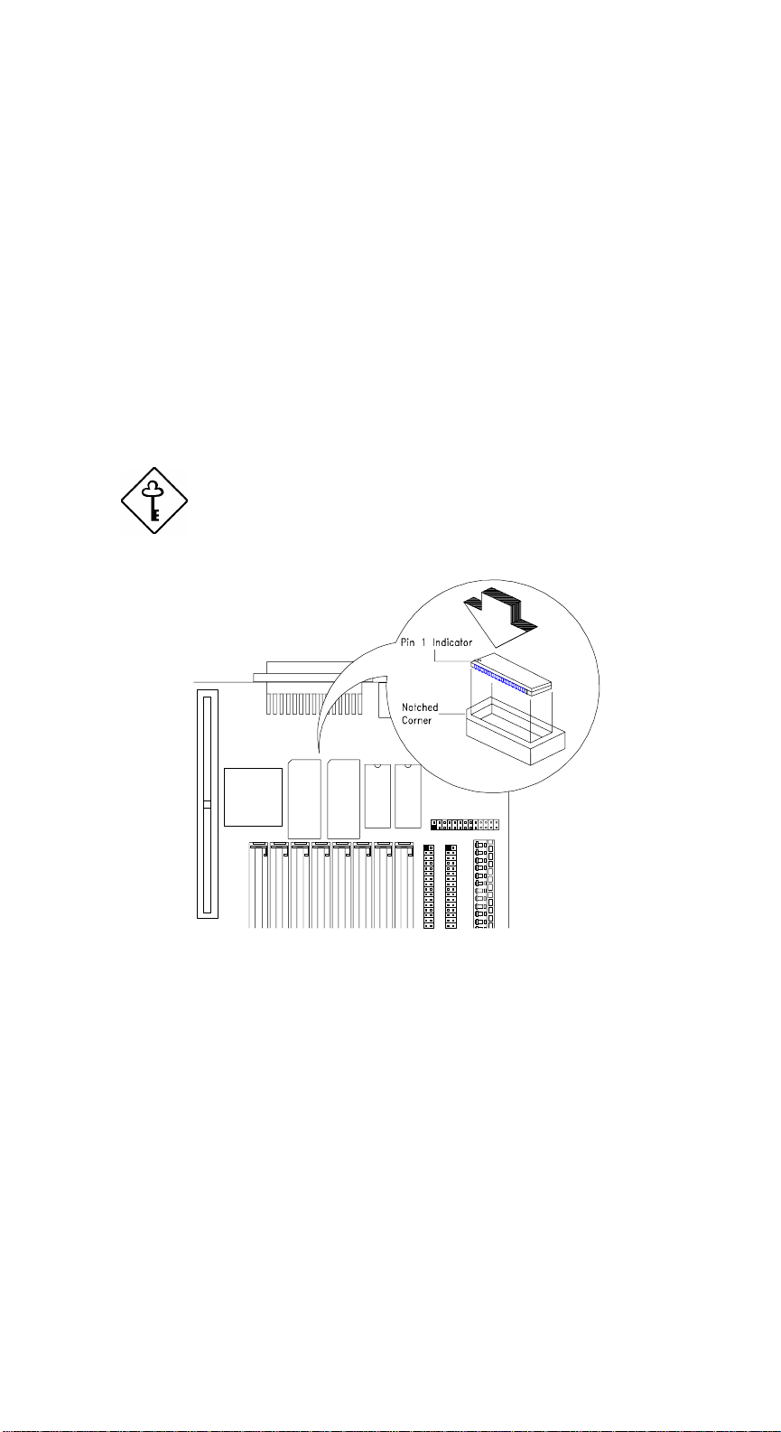
1. Locate the video DRAM upgrade sockets labeled U18 and U21 on the system
board. See Figure 1-1.
2. Gently insert a video chip into each of the upgrade sockets.
Make sure that the pin 1 indicator on the chip
matches the notched corner of the socket.
Figure 2-5 Installing a Video Memory Chip
AcerAltos 9000 User’s Guide
2-12
Page 61

2.8 PCI Slot Configuration
2.8.1 PCI-to-PCI Bridge Feature
The system board carries a PCI-to-PCI bridge controller chipset that expands the
capability of the PCI system by allowing all the five PCI slots in the system to be
bus masters. The bridge has two interfaces. The primary interface connects
directly to the PCI bus close to the host CPU. The secondary interface creates a
new PCI bus that can operate independently from the primary PCI bus. Refer to
Figure 2-1.
2.8.2 Installing PCI Devices
The devices you install in PCI slots 1 and 2 operate on the primary PCI bus while
those in PCI slots 3, 4, and 5 operate on the secondary PCI bus.
Since the primary PCI bus has a quicker response time than the secondary PCI
bus, install PCI add-on boards in PCI slots 1 and 2 first then in PCI slots 3, 4, and
5 to enhance system performance. See Figure 2-1 for the locations of the PCI slots.
Chapter 2 - System Board
2-13
Page 62

2.9 Error Messages
Do not continue using the computer if you receive an error message of any type.
Note the message and take corrective action. This section explains the different
types of error messages and corresponding corrective measures.
There are two general types of error messages:
• Software
• System
2.9.1 Software Error Messages
Software error messages are returned by your operating system or application.
These messages typically occur after you boot the operating system or when you
run your applications. If you receive this type of message, consult your
application or operating system manual for help.
2.9.2 System Error Messages
A system error message indicates a problem with the computer itself. A message
of this type normally appears during the power-on self-test, before the operating
system prompt appears.
Table 2-4 lists the system error messages.
AcerAltos 9000 User’s Guide
2-14
Page 63
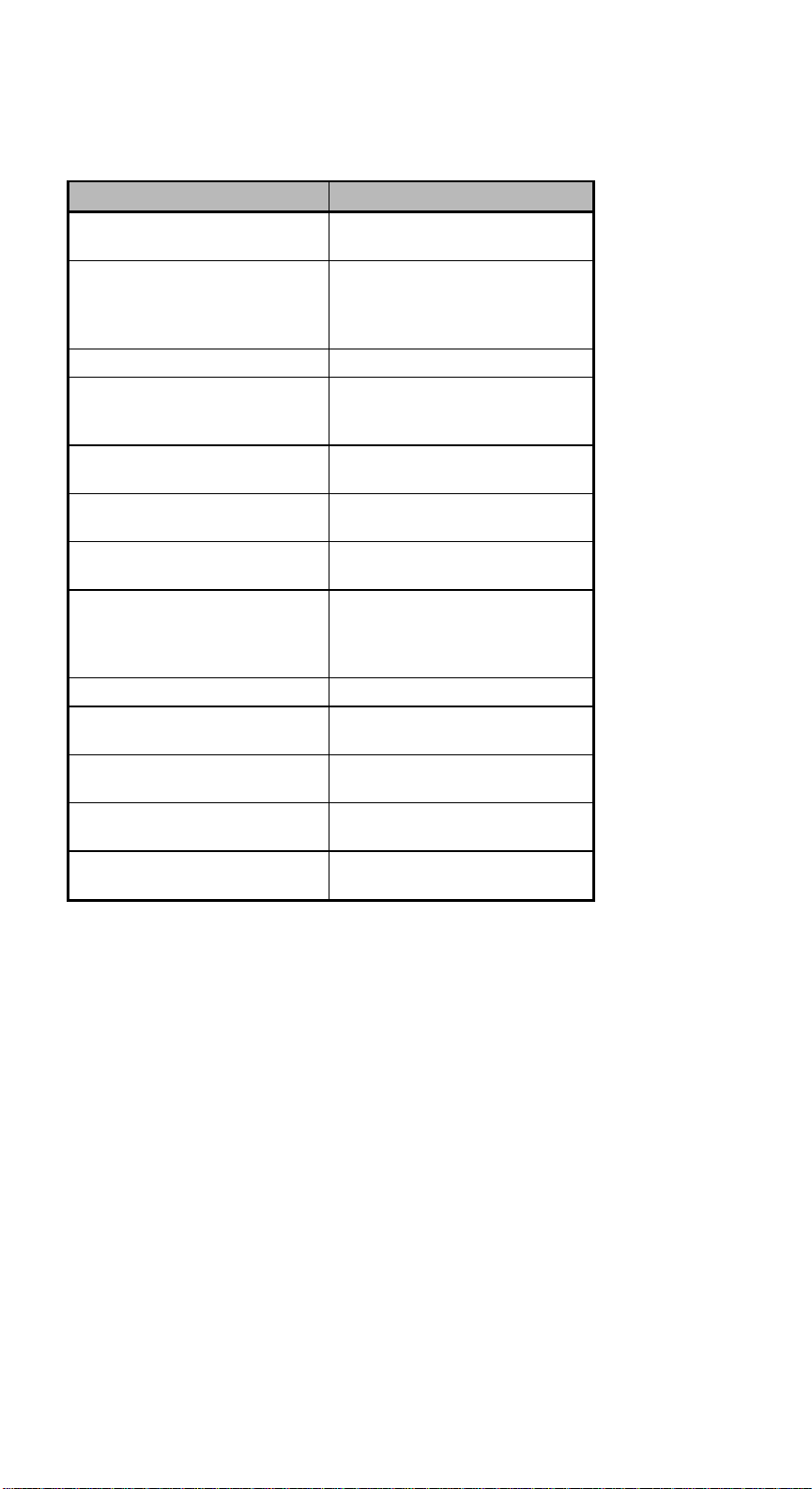
Table 2-4 System Error Messages
Message Action
CMOS Battery Error Replace the RTC chip or
contact your dealer.
CMOS Checksum Error Check the RTC chip and the
necessary jumper. If the
battery is still good, run
Setup.
Display Card Mismatch Run Setup.
Diskette Drive Controller
Error or Not Installed
Diskette Drive Error Diskette may be defective. If
Diskette Drive A Type
Mismatch
Diskette Drive B Type
Mismatch
Equipment Configuration
Error
Hard disk Controller Error Run Setup.
Hard disk 0 Error Check all cable connections.
Hard disk 1 Error Check all cable connections.
Keyboard Error or No
Keyboard Connected
Keyboard Interface Error Replace the keyboard or
Check and connect the
control cable to the diskette
controller.
not, replace the diskette drive.
Run Setup and select the
proper drive type.
Run Setup and select the
proper drive type.
Modify the memory
configuration to agree with
one of the options in Table
2-3.
Replace hard disk.
Replace hard disk.
Check and connect the
keyboard to the system unit.
contact your dealer.
Chapter 2 - System Board
2-15
Page 64
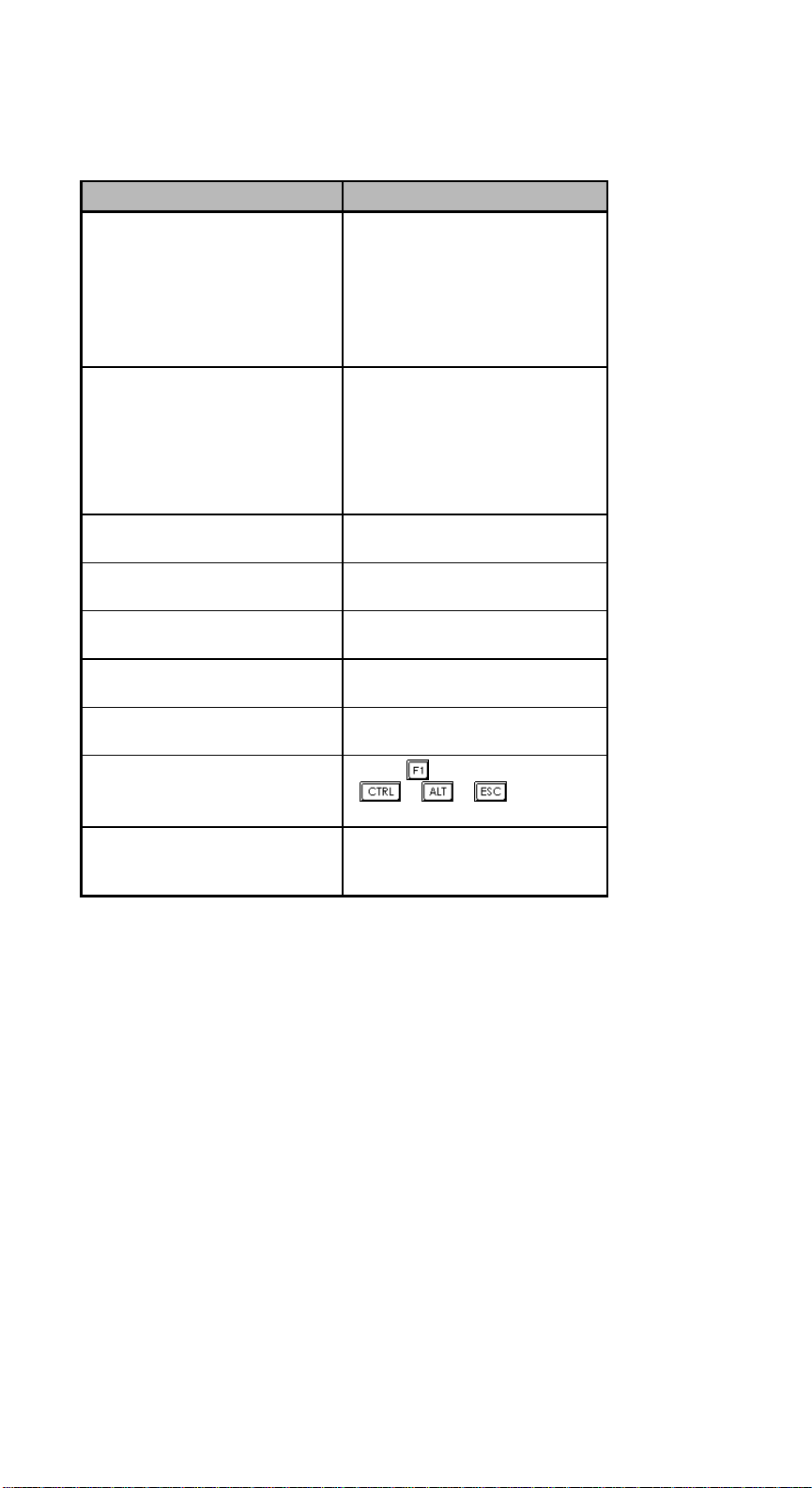
Table 2-4 System Error Messages (continued)
Message Action
Memory Error at:
MMMM:SSSS:OOO
(W:XXXX, R:YYYY)
where:
M: MB, S: Segment,
O: Offset, X/Y: write/read
pattern
Memory Size Mismatch
CPU Clock Mismatch
Onboard Serial Port 1
Conflict
Onboard Serial Port 2
Conflict
Onboard Parallel Port
Conflict
Pointing Device Error Check and connect pointing
Pointing Device Interface
Error
Press F1 key to continue or
Ctrl-Alt-Esc for Setup
Real Time Clock Error Check the RTC chip. If it is
Check SIMMs on the system
board. Contact your dealer.
Run Setup. Check if the
values shown in the memory
parameters are correct. If
correct, exit Setup and reboot
the system. If the error
message reappears, seek
technical assistance.
Run Setup and disable the
port.
Run Setup and disable the
port.
Run Setup and disable the
port.
device.
Replace the pointing device or
contact your dealer.
Press
Setup.
still good, run Setup. If not,
replace the RTC chip.
or
+ + to enter
AcerAltos 9000 User’s Guide
2-16
Page 65

2.9.3 Correcting Error Conditions
As a general rule, if an error message says "Press F1 to continue," it is caused by a
configuration problem, which can be easily corrected. An equipment malfunction
is more likely to cause a fatal error, i.e., an error that causes complete system
failure.
Here are some corrective measures for error conditions:
1. Run Setup and ECU. You must know the correct configuration values for
your system before you enter Setup, which is why you should write them
down when the system is correctly configured. An incorrect configuration is
a major cause of power-on error messages, especially for a new system.
2. Remove the system unit cover. Check that the jumpers on the system board
and any expansion boards are set correctly.
3. If you cannot access a new disk, it may be because your disk is not properly
formatted.
4. Check that all connectors and boards are securely plugged in.
If you go through the corrective steps above and still receive an error message,
the cause may be an equipment malfunction.
If you are sure that your configuration values are correct and your battery is in
good condition, the problem may lie in a damaged or defective chip.
In either case, contact an authorized service center for assistance.
Chapter 2 - System Board
2-17
Page 66

AcerAltos 9000 User’s Guide
2-18
Page 67

Chapter 3 BIOS Utility
Most systems are already configured by the manufacturer or the dealer. There is
no need to run Setup when starting the computer unless you get a Run Setup
message.
The Setup program loads configuration values into the battery-backed nonvolatile
memory called CMOS RAM. This memory area is not part of the system RAM.
If you repeatedly receive Run Setup
messages, the battery may be bad. In this
case, the system cannot retain configuration
values in CMOS. Ask a qualified technician
for assistance.
Before running Setup, have the following information ready:
• Diskette drive type The standard type is a 3.5-inch 1.44 MB diskette drive.
Chapter 3 - BIOS Utility
3-1
Page 68
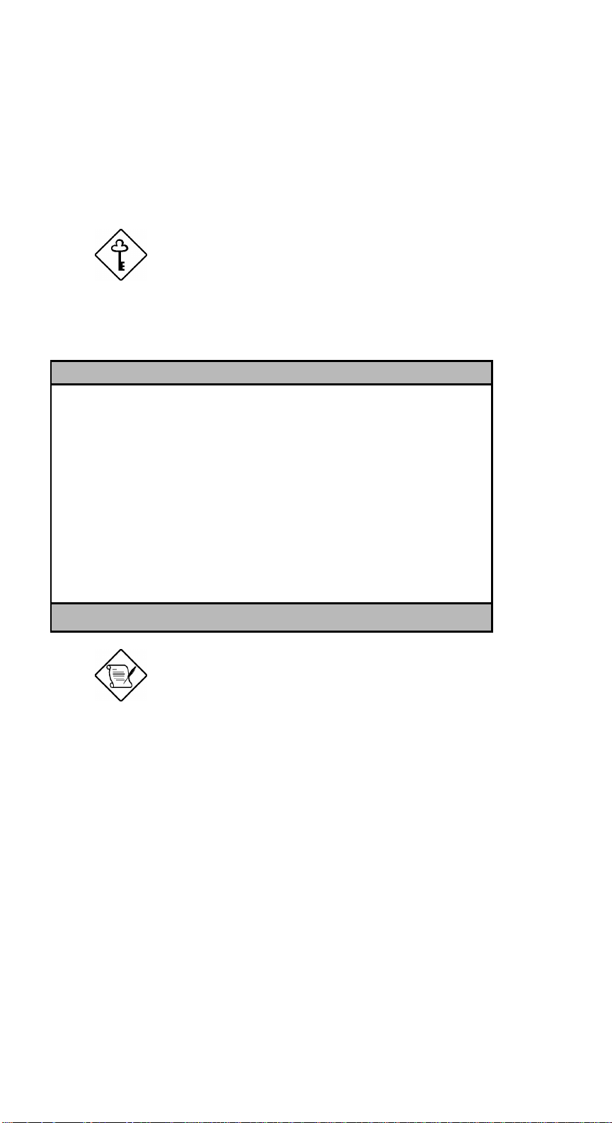
3.1 Entering Setup
To enter Setup, press the key combination b+a+^.
You must press b+a+^ while
the system is booting. This key combination
does not work any other time.
The BIOS Utility main menu then appears:
BIOS Utility
Basic System Configuration
Advanced System Configuration
PCI System Configuration
Non-PnP ISA Card Configuration
Power Saving Configuration
Remote Diagnostic Configuration
System Security
Load Setup Default Settings
↑↓ = Move Highlight Bar, ← = Select, Esc = Exit and Reboot
The parameters on the screens show default
values. These values may not be the same
as those in your system.
The grayed items (denoted with asterisks) on
the screens have fixed settings and are not
user-configurable.
AcerAltos 9000 User’s Guide
3-2
Page 69
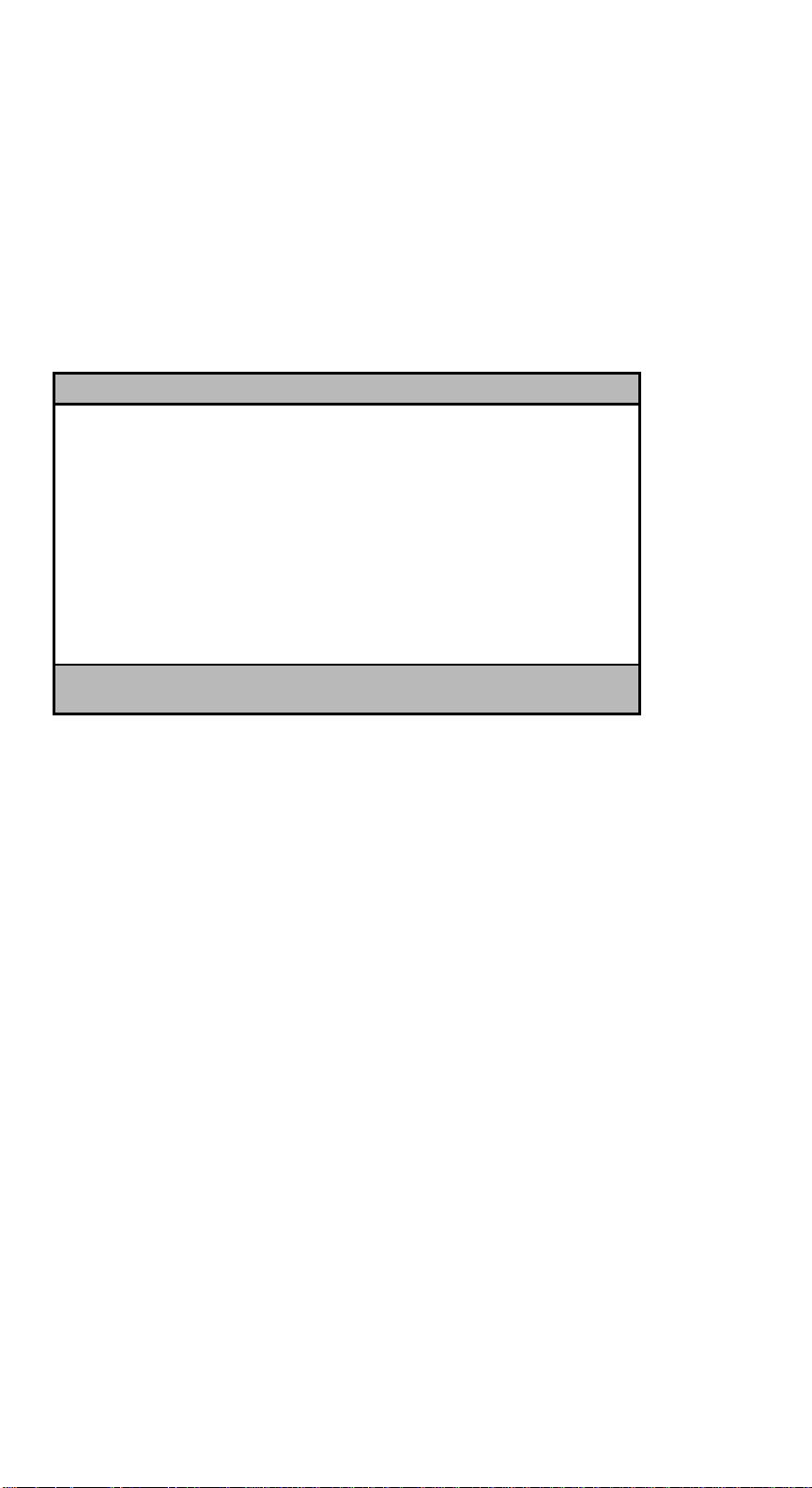
3.2 Basic System Configuration
Select Basic System Configuration to input configuration values such as date,
time, and disk types.
The following screen shows the Basic System Configuration menu.
Basic System Configuration Page 1/2
Date ..................... [MM/DD/YY]
Time ..................... [HH:MM:SS]
Diskette Drive A ......... [1.44 MB 3.5-inch]
Diskette Drive B ......... [None]
Cylinder Head Sector
Hard Disk 0 (xxx MB)..... [None] xx xx xx
Hard Disk 1 (xxx MB)..... [None] xx xx xx
*Base Memory ............. [ 640] KB
*Extended Memory ......... [ xxxx] KB
*Total Memory ............ [ xxxx] KB
*Math Coprocessor ........ [ Installed ]
*Video Display ........... [VGA/EGA]
↑↓ = Move Highlight Bar, → ← = Change Setting
PgDn/PgUp = Move Screen, F1 = Help, Esc = Exit
The command line at the bottom of the menu tells you how to highlight items,
change settings, and move from one screen to another.
w or y on the cursor-edit keypad to highlight the desired parameter.
Press
Press
x or z to select the desired option for an item.
Press
}to move to the next page or {to return to the previous page.
Press
^ to exit the configuration menu.
Chapter 3 - BIOS Utility
3-3
Page 70

The following screen shows page 2 of the Basic System Configuration menu.
Basic System Configuration Page 2/2
Communication Settings
Baud Rate ..................... [9600] BPS
Parity ........................ [None]
Stop Bits ..................... [1] Bits
Data Length ................... [8] Bits
Enhanced IDE Features
Hard Disk Block Mode .......... [Disabled]
Hard Disk Size > 504MB ........ [Disabled]
Large Memory Support Mode ......... [ Normal ]
Num Lock After Boot .............. [Enabled ]
Memory Test ...................... [Disabled]
Auto Configuration Mode ........... [Disabled ]
Fast Boot Mode ................... [Disabled ]
↑↓ = Move Highlight Bar, → ← = Change Setting
PgDn/PgUp = Move Screen, F1 = Help, Esc = Exit
The following sections explain the different parameters and their settings.
AcerAltos 9000 User’s Guide
3-4
Page 71

3.2.1 Date and Time
The real-time clock keeps the system date and time. After setting the date and
time, you need not enter them every time you turn on the system. As long as the
internal battery remains good (approximately seven
clock continues to keep the date and time accurately even when the power is off.
Date
years) and connected, the
Highlight the items on the date parameter and press
following the month-day-year format.
Valid values for month, day, and year are:
• Month 1 to 12
• Day 1 to 31
• Year 00 to 99
Time
Highlight the items on the time parameter and press
following the hour-minute-second format.
Valid values for hour, minute, and second are:
• Hour 00 to 23
• Minute 00 to 59
• Second 00 to 59
x or z to set the date
x or z to set the time
Chapter 3 - BIOS Utility
3-5
Page 72

3.2.2 Diskette Drives
To enter the configuration value for the first diskette drive (drive A), highlight the
Diskette Drive A parameter. Press
the appropriate value.
Possible settings for the Diskette Drive parameters:
• [ None ]
• [360 KB, 5.25-inch]
• [1.2 MB, 5.25-inch]
• [720 KB, 3.5-inch]
• [1.44 MB, 3.5-inch]
• [2.88 MB, 3.5-inch]
Follow the same procedure for Diskette Drive B. Choose None if you do not have
a second diskette drive.
x or z key to view the options and select
3.2.3 Hard Disk Drives
Move the highlight bar to the hard disk 0 parameter to configure the first hard
disk (drive C). Press
values. Select the type that corresponds to your hard disk drive. Follow the same
procedure for the other hard disks, if any. Choose None if you do not have other
drives or are booting from a SCSI hard drive. The default setting is None.
x or z to display the hard disk types with their respective
When booting from a SCSI fixed disk installation, have both of these options
set to None.
The following sections, “Selecting the Auto
Option” and “Selecting the User Option,”
describe functions used for IDE drives only.
AcerAltos 9000 User’s Guide
3-6
Page 73
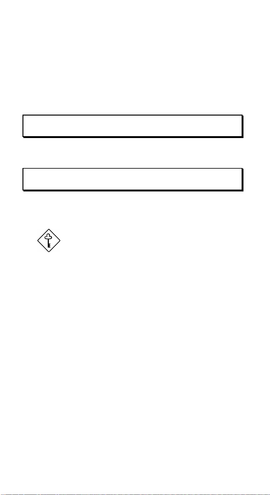
Selecting the “Auto” Option
If you do not know the exact type of your IDE fixed disk, select the option Auto.
During the power-on self-test (POST), when the system performs self-testing and
self-initialization before loading the operating system and applications, the BIOS
utility automatically determines your hard disk type. You can see the drive type
and its values when you enter the BIOS Utility.
Cylinder Head Sector
Hard Disk 0 (xx MB) ... [Auto] xx xx xx
If desired, you can save the values under the option User.
Cylinder Head Sector
Hard Disk 0 (xx MB) ... [User] xx xx xx
The next time you boot the system, the BIOS utility does not have to autoconfigure your hard disk as it detects the saved disk information during POST.
We recommend that you copy the IDE disk
drive values and keep them in a safe place in
case you have to reconfigure the disk in the
future.
Follow the same procedure to auto-configure other IDE hard disks.
Chapter 3 - BIOS Utility
3-7
Page 74

Selecting the “User” Option
There are cases when you cannot use the option Auto, instead you have to select
User. Choose the User option when you have installed an IDE fixed disk that
was previously formatted but does not use the disk native parameters or
structure, that is, the disk type may be in the hard disk types list but the number
of cylinders, heads, and sectors differ.
Follow these steps to configure a hard disk with the User option:
1. Highlight a hard disk parameter.
2. Select the option User and press
3. Type in the number of cylinders, heads, and sectors of the drive under the
appropriate columns.
Be sure to have the correct hard disk
information beforehand.
4. Choose Yes when asked if you want to save CMOS data.
e.
3.2.4 System Memory
The system automatically detects the total amount of onboard memory during the
POST and sets the memory parameters accordingly. If you install additional
memory, the system adjusts the Total Memory parameter to display the new
memory size (refer to section 2.6.5). When changing your system’s memory
configuration, be sure to run the ECU to add in the changes.
AcerAltos 9000 User’s Guide
3-8
Page 75

3.2.5 Math Coprocessor
The CPU includes a math coprocessor so this parameter shows Installed by
default.
3.2.6 Video Display
The video display is the monitor on which the operating system prompt appears
when you boot the system. The system automatically detects the video mode of
your primary display and sets the configuration value accordingly. Values for
this parameter are:
• [Monochrome]
• [CGA 40 columns x 25 rows]
• [CGA 80 columns x 25 rows]
• [VGA/EGA]
3.2.7 Communication Settings
The Communication Settings parameters allow you to set the baud rate, parity,
stop bit and data length for the first serial port (COM 1). The values for this
parameter are:
• Baud rate : 110 to 9600 bits per second (BPS)
• Parity : odd, even, or none
• Stop bit : 1 or 2 stop bits
• Data length : 7- or 8-bit data word
The baud rate maximum value 9600 BPS
applies only to POST under UNIX
environment. The system I/O chipset
SMC 37C665 supports up to 115.2K BPS.
Chapter 3 - BIOS Utility
3-9
Page 76

3.2.8 Enhanced IDE Features
Hard Disk Block Mode
This function enhances disk performance depending on the hard disk in use. If
you set this parameter to Enabled, it allows data transfer in block (multiple
sectors) by increasing the data transfer rate to 256 bytes per cycle. If your system
does not boot after enabling this parameter, change the setting to Disabled. This
parameter is normally set to Disabled.
Hard Disk Size > 504 MB
This enhanced IDE feature works only under DOS and Windows 3.x
environments. If enabled, it allows you to use a hard disk with a capacity of more
than 504 MB. This is made possible through the Logical Block Address (LBA)
mode translation. Other operating systems require this parameter to be set to
Disabled.
To prevent data loss, set this parameter set to Enabled if you are using a hard
disk with more than 504 MB capacity that was previously configured through
LBA mode. If you use a hard disk configured through cylinder-head-sector
(CHS) mode, set this item to Disabled.
3.2.9 Large Memory Support Mode
This parameter allows the system to support an extended memory higher than
64 MB. Set this parameter to Advanced if you are working under Windows NT
environment and the system memory size is greater than or equal to 64 MB,
otherwise, set it to Normal. The default setting is Normal.
AcerAltos 9000 User’s Guide
3-10
Page 77

3.2.10 Num Lock After Boot
This parameter allows you to activate the Num Lock function upon booting. The
default setting is Enabled.
3.2.11 Memory Test
When set to Enabled, this parameter allows the system to perform a RAM test
during the POST routine. When set to Disabled, the system detects only the
memory size and bypasses the test routine. The default setting is Disabled.
This item is fixed to Disabled and is not user-configurable if you enabled the
Auto Configuration Mode and the Fast Boot Mode parameters on page 2 of the
Basic System Configuration menu. See sections 3.2.12 and 3.2.13.
3.2.12 Auto Configuration Mode
When enabled, this parameter automatically sets the system configuration values
to their optimized settings. At the same time, it causes the Memory Test
parameter to be fixed to Disabled and the shadow RAM regions for system and
video BIOS to Enabled. See sections 3.2.11 and 3.3.1.
This parameter is Disabled by default.
3.2.13 Fast Boot Mode
When enabled, this parameter allows the system to boot faster by skipping some
POST routines. It bypasses memory test, enables Shadow RAM, and enables
primary- and second-level cache. This parameter is Disabled by default.
When set to Enabled, this parameter causes the Memory Test parameter to be
fixed to Disabled and the shadow RAM regions for system and video BIOS to
Enabled. See sections 3.2.11 and 3.3.1.
Chapter 3 - BIOS Utility
3-11
Page 78
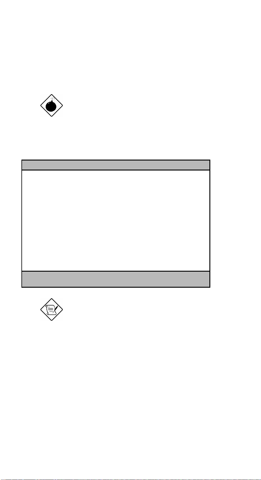
3.3 Advanced System Configuration
The Advanced System Configuration option allows you to configure the
advanced system memory functions.
To avoid damaging the system, do not
change any settings in the Advanced
Configuration unless you are a qualified
technician.
The following screen shows page one of the Advanced System Configuration
parameters.
Advanced System Configuration Page 1/1
Shadow RAM
*E0000h - FFFFFh (System BIOS) ... [Enabled ]
*C0000h - C7FFFh (Video BIOS) ..... [Enabled ]
C8000h - CBFFFh ................. [Disabled]
CC000h - CFFFFh ................. [Disabled]
D0000h - D3FFFh .................. [Disabled]
D4000h - D7FFFh ................. [Disabled]
D8000h - DBFFFh ................. [Disabled]
DC000h - DFFFFh ................. [Disabled]
Internal Cache (CPU Cache) ......... [Enabled ]
External Cache ..................... [Enabled ]
ECC/Parity Mode Selection .......... [ ECC ]
*Operation of ECC ................ [ None ]
Memory at 15MB-16MB Reserved for .... [ System ] Use
↑↓ = Move Highlight Bar, → ← = Change Setting
PgDn/PgUp = Move Screen, F1 = Help, Esc = Exit
The grayed parameters (denoted with
asterisks) are not user-configurable.
AcerAltos 9000 User’s Guide
3-12
Page 79

3.3.1 Shadow RAM
The system reserves 384 KB of random access memory (RAM) for the shadow
RAM function. This parameter has eight range addresses. When you set these
addresses to Enabled, the system BIOS, video BIOS, and I/O ROM functions run
directly from the shadow RAM for faster operation. When you set them to
Disabled, the functions run normally from ROM.
The address range E0000h - FFFFFh is for shadowing the system BIOS. This item
is always set to Enabled and is not user-configurable. The address range
C0000h - C7FFFh is for shadowing the video BIOS. This item is fixed to Enabled
and is not user-configurable if the Auto Configuration Mode and the Fast Boot
Mode parameters on page 2 of the Basic System Configuration menu are enabled.
Otherwise, you can choose to disable this item.
The remaining address ranges are for I/O ROM functions.
3.3.2 Internal Cache (CPU Cache)
This parameter enables or disables the internal cache memory. This item is fixed
to Enabled and is not user-configurable if you enabled the Auto configuration
Mode and Fast Boot Mode parameters on page 2 of the Basic System
Configuration menu. Otherwise, you can choose to disable this item. The default
setting is Enabled.
3.3.3 External Cache
This parameter enables or disables the external cache memory. This item is fixed
to Enabled and is not user-configurable if you enabled the Auto Configuration
Mode and Fast Boot Mode parameters on page 2 of the Basic System
Configuration menu. Otherwise, you can choose to disable this item. The default
setting is Enabled.
Chapter 3 - BIOS Utility
3-13
Page 80

3.3.4 ECC/Parity Mode Selection
This parameter allows you to enable or disable the ECC and parity check feature.
Fast-page mode SIMMs support both ECC and parity mode while EDO SIMMs
support only ECC mode.
You must disable this parameter if you installed SIMMs without parity.
Operation of ECC
This parameter is not user-configurable.
3.3.5 Memory at 15MB-16MB
To prevent memory address conflicts between the system and expansion boards,
reserve this memory range for the use of either the system or an expansion board.
Before setting this parameter, check your add-on card manual to determine if
your add-on card needs this memory space. If not, the default setting is System
Use.
AcerAltos 9000 User’s Guide
3-14
Page 81

3.4 PCI System Configuration
The PCI System Configuration allows you to specify the settings for your PCI
devices.
PCI System Configuration Page 1/1
PCI IRQ Setting ........... [ Auto ]
*PCI Slot 1 ........... [--] [--] [9 ] [11]
*PCI Slot 2 ........... [--] [9 ] [11] [--]
*PCI Slot 3 ........... [--] [--] [--] [--]
*PCI Slot 4 ........... [--] [--] [--] [--]
*PCI Slot 5 .......... [--] [--] [--] [--]
*Onboard VGA...... .... [9 ]
*Onboard SCSI..... .... [11]
VGA Palette Snoop ......... [Disabled]
Onboard SCSI .............. [Enabled ]
Boot Device ........... [Enabled]
↑↓ = Move Highlight Bar, → ← = Change Setting
PgDn/PgUp = Move Screen, F1 = Help, Esc = Exit
INTA INTB INTC INTD
Chapter 3 - BIOS Utility
3-15
Page 82

3.4.1 PCI IRQ Setting
This parameter allows for Auto or Manual configuration of PCI devices. If you
use plug-and-play (PnP) devices, you can keep the default setting Auto. The
system then automatically configures the PnP devices. If your PCI device is not a
PnP, you can manually assign the interrupt for each device. Refer to your manual
for technical information about the PCI card.
PCI Slots
These parameters allow you to specify the appropriate interrupt for each of the
PCI devices. You can assign IRQ3, IRQ4, IRQ5, IRQ7, IRQ9, IRQ10, IRQ11,
IRQ12, or IRQ15 to the slots.
Make sure that the interrupt you assign in
any of the PCI slots are not used by other
devices to avoid conflicts. Some resources
may be assigned only after disabling onboard
devices.
Use the w or y key to move between fields. Use the x or z key to select
options.
AcerAltos 9000 User’s Guide
3-16
Page 83

3.4.2 VGA Palette Snoop
PCI devices support a palette snooping technique that enables the device to
control access to their palette registers. Set this parameter to Enabled to activate
the palette snooping function in the PCI VGA devices installed in your system.
Check your VGA card manual for more information about this function. The
default setting is Disabled.
3.4.3 Onboard SCSI
This parameter allows you to enable or disable the onboard SCSI controller. The
default setting is Enabled.
Boot Device
This parameter allows you to enable or disable the onboard SCSI as the boot
controller. The default setting is Enabled.
3.5 Non-PnP ISA Card Configuration
The Non-PnP ISA Card Configuration parameters allow you to specify the
settings for cards without plug-and-play (PnP) features.
Chapter 3 - BIOS Utility
3-17
Page 84
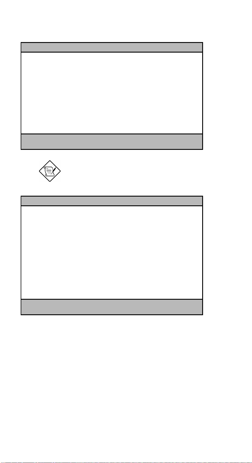
Non-PnP ISA Card Configuration Page 1/2
System Resources Used by Non-PnP ISA Cards
IRQ 00 ... [---]* IRQ 08 ... [---]* DMA 0 ... [No ]
IRQ 01 ... [---]* IRQ 09 ... [No ] DMA 1 ... [No ]
IRQ 02 ... [---]* IRQ 10 ... [No ] DMA 2 ... [---]*
IRQ 03 ... [No ] IRQ 11 ... [No ] DMA 3 ... [No ]
IRQ 04 ... [No ] IRQ 12 ... [No ] DMA 4 ... [---]*
IRQ 05 ... [No ] IRQ 13 ... [---]* DMA 5 ... [No ]
IRQ 06 ... [---]* IRQ 14 ... [---]* DMA 6 ... [No ]
IRQ 07 ... [No ] IRQ 15 ... [No ] DMA 7 ... [No ]
Expansion ROM Region
C8000h - CBFFFh .... [No ] D4000h - D7FFFh .... [No ]
CC000h - CFFFFh .... [No ] D8000h - DBFFFh .... [No ]
D0000h - D3FFFh .... [No ] DC000h - DFFFFh .... [No ]
↑↓ = Move Highlight Bar, → ← = Change Setting
PgDn/PgUp = Move Screen, F1 = Help, Esc = Exit
The grayed items (denoted with asterisks)
have fixed settings and are not userconfigurable.
Non-PnP ISA Card Configuration Page 2/2
I/O Region
100h-10Fh .. [No ] 200h-20Fh . [No ] 300h-30Fh .. [No ]
110h-11Fh .. [No ] 210h-21Fh . [No ] 310h-31Fh .. [No ]
120h-12Fh .. [No ] 220h-22Fh . [No ] 320h-32Fh .. [No ]
130h-13Fh .. [No ] 230h-23Fh . [No ] 330h-33Fh .. [No ]
140h-14Fh .. [No ] 240h-24Fh . [No ] 340h-34Fh .. [No ]
150h-15Fh .. [No ] 250h-25Fh . [No ] 350h-35Fh .. [No ]
160h-16Fh .. [No ] 260h-26Fh . [No ] 360h-36Fh .. [No ]
170h-17Fh .. [No ] 270h-27Fh . [No ] 370h-37Fh .. [No ]
180h-18Fh .. [No ] 280h-28Fh . [No ] 380h-38Fh .. [No ]
190h-19Fh .. [No ] 290h-29Fh . [No ] 390h-39Fh .. [No ]
1A0h-1AFh .. [No ] 2A0h-2AFh . [No ] 3A0h-3AFh .. [No ]
1B0h-1BFh .. [No ] 2B0h-2BFh . [No ] 3B0h-3BFh .. [No ]
1C0h-1CFh .. [No ] 2C0h-2CFh . [No ] 3C0h-3CFh .. [No ]
1D0h-1DFh .. [No ] 2D0h-2DFh . [No ] 3D0h-3DFh .. [No ]
1E0h-1EFh .. [No ] 2E0h-2EFh . [No ] 3E0h-3EFh .. [No ]
1F0h-1FFh .. [---]* 2F0h-2FFh . [No ] 3F0h-3FFh .. [No ]
↑↓ = Move Highlight Bar, → ← = Change Setting
PgDn/PgUp = Move Screen, F1 = Help, Esc = Exit
AcerAltos 9000 User’s Guide
3-18
Page 85

Refer to your non-PnP ISA card manual
when setting the following parameters.
3.5.1 IRQ/DMA
This parameter allows you to assign specific IRQ and DMA channels to non-PnP
ISA cards. The system will not use such IRQ and DMA channels when it
automatically assigns channels to PnP cards.
3.5.2 Expansion ROM Region
This parameter specifies the memory regions available for add-on card use. It
allows you to manually assign specific regions to non-PnP cards so that the
system will not use those regions anymore when it automatically configures PnP
cards.
3.5.3 I/O Region
The items under this parameter allow you to reserve 16-byte memory address
ranges for non-PnP cards. When the system configures PnP cards, the address
ranges that you marked will not be used anymore.
You can assign memory addresses to non-PnP cards at random as long as you
cover the address range required by the card. For example, for a card that
requires 178h-188h address, you have to set regions 170h-17Fh and 180h-18Fh to
Yes.
Chapter 3 - BIOS Utility
3-19
Page 86
3.6 Power Saving Configuration
The Power Saving Configuration parameters are configurable only if your system
supports the power management feature.
Most multi-user operating systems do not
support a Power Saving feature. Consult
your operating system manual or call your
operating system vendor for information.
The following screen shows the Power Saving Configuration parameters and their
default settings:
Power Saving Configuration Page 1/1
Power Management Mode ................[Disabled]
*IDE Fixed Disk Standby Timer .....[OFF]
*System Standby Timer .............[OFF]
System/Wakeup Events
IRQ 0 ...... [Disabled]* IRQ 8 ...... [Disabled]
IRQ 1 ...... [Enabled ]* IRQ 9 ...... [Disabled]
IRQ 3 ...... [Disabled] IRQ 10 ..... [Disabled]
IRQ 4 ...... [Disabled] IRQ 11 ..... [Disabled]
IRQ 5 ...... [Disabled] IRQ 12 ..... [Enabled ]*
IRQ 6 ...... [Disabled] IRQ 13 ..... [Disabled]
IRQ 7 ...... [Disabled] IRQ 14 ..... [Disabled]
IRQ 15 ..... [Disabled]
↑↓ = Move Highlight Bar, → ← = Change Setting
PgDn/PgUp = Move Screen, F1 = Help, Esc = Exit
AcerAltos 9000 User’s Guide
3-20
Page 87

3.6.1 Power Management Mode
This parameter allows you to reduce power consumption. When this parameter
is set to Enabled, you can configure the system timers. Setting to Disabled
deactivates the power management feature and all the timers. The default setting
is Disabled.
IDE Fixed Disk Standby Timer
This parameter allows the hard disk to enter standby mode after inactivity of 1 to
15 minutes, depending on your setting. When you access the hard disk again,
allow 3 to 5 seconds (depending on the hard disk) for the disk to return to the
normal speed. Set this parameter to Off if your hard disk does not support this
function.
System Standby Timer
This parameter sets the system to a "fast-on" power saving mode. It
automatically enters the standby mode after a specified period of inactivity. Any
keyboard or mouse action, or any enabled monitored activities occurring through
the IRQ channels, resume system operation. See section 3.6.2.
3.6.2 System/Wakeup Events
This parameter allows you to monitor system activities occurring through the IRQ
and determine whether or not to enter power saving mode.
For example, if you assign IRQ 3 to a fax/modem and you set this item to
Enabled, any fax/modem activity wakes up the system from suspend mode.
Chapter 3 - BIOS Utility
3-21
Page 88
3.7 System Security Setup
The Setup program has a number of security features to prevent unauthorized
access to the system and its data.
Enter the Setup program and select System Security. The following screen
appears:
System Security Page 1/1
Disk Drive Control
Diskette Drive ................. [ Normal ]
Hard Disk Drive ................ [ Normal ]
System Boot Drive .............. [Drive A then C]
Onboard Communication Ports
Serial Port 1 Base Address ..... [ 3F8h ]
Serial Port 2 Base Address ..... [ 2F8h ]
Parallel Port Base Address ..... [3BC (IRQ 7]
Operation Mode .............. [Enhanced Parallel Port (EPP)] Mode
*ECP DMA Channel......... [-]
Onboard PS/2 Mouse (IRQ12) ... [Enabled ]
Setup Password ................... [ None ]
Power On Password ................ [ None ]
↑↓ = Move Highlight Bar, → ← = Change Setting
PgDn/PgUp = Move Screen, F1 = Help, Esc = Exit
3.7.1 Disk Drive Control
The disk drive control features allow you to enable or disable the read/write
functions of a disk drive. These features can also control the diskette drive or the
hard disk drive boot function to prevent loading operating systems or other
programs from a certain drive while the other drives are operational.
Table 3-1 lists the drive control settings and their corresponding functions.
AcerAltos 9000 User’s Guide
3-22
Page 89
Table 3-1 Drive Control Settings
Diskette Drive
Setting Description
Normal Diskette drive functions normally
Write Protect All Sectors Disables the write function on all sectors
Write Protect Boot Sector Disables the write function only on boot
sector
Disabled Disables all diskette functions
Hard Disk Drive
Setting Description
Normal Hard disk drive functions normally
Write Protect All Sectors Disables the write function on all sectors
Write Protect Boot Sector Disables the write function only on boot
sector
Disabled Disables all hard disk functions
System Boot Drive
Setting Description
Drive A then C System boots from drive A to C
Drive C then A System boots from drive C to A
C: System always boots from drive C
A: System always boots from drive A
Chapter 3 - BIOS Utility
3-23
Page 90
3.7.2 Onboard Communication Ports
Serial Port 1 Base Address
This parameter enables serial port 1 as COM1 and sets its base address.
Table 3-2 Serial Port 1 Settings
Setting Function
Serial 1 (3F8h) COM1 with address 3F8h
2F8h COM2 with address 2F8h
3E8h COM3 with address 3E8h
2E8h COM4 with address 2E8h
Disabled Disables serial port 1
Serial Port 2 Base Address
This parameter enables serial port 2 as COM2 and sets its base address.
Table 3-3 Serial Port 2 Settings
Setting Function
Serial 2 (2F8h) COM2 with address 2F8h
3F8h COM1 with address 3F8h
2E8h COM4 with address 2E8h
3E8h COM3 with address 3E8h
Disabled Disables serial port 2
AcerAltos 9000 User’s Guide
3-24
Page 91
Parallel Port Base Address
The system has one parallel port. Table 3-4 lists the options for selecting the
parallel port address. You also have the option to disable the parallel port.
Table 3-4 Parallel Port Settings
Setting Function
3BCh (IRQ 7) Corresponds to the parallel port with
address 3BCh
378h (IRQ 7) Corresponds to the parallel port with
address 378h
278h (IRQ 5) Corresponds to the parallel port with
address 278h
Disabled Disables the parallel port
To deactivate the parallel port, select the Disabled option. If you install an addon card that has a parallel port whose address conflicts with the parallel port
onboard, the system automatically disables the onboard functions.
Check the parallel port address on the add-on card and change the address to one
that does not conflict. The default setting is 3BCh.
Chapter 3 - BIOS Utility
3-25
Page 92

Operation Mode
This item allows you to set the operation mode of the parallel port. Table 3-5 lists
the different operation modes. The default setting is EPP.
Table 3-5 Parallel Port Operation Mode Settings
Setting Function
Standard Parallel Port (SPP) Allows normal speed one-way
operation
Standard and Bidirectional Allows normal speed operation in
a two-way mode
Enhanced Parallel Port (EPP) Allows bidirectional parallel port
operation at maximum speed
Extended Capabilities Port
(ECP)
Allows parallel port to operate in
bidirectional mode and at a speed
higher than the maximum data
transfer rate
ECP DMA Channel
This item becomes active only if you select Extended Capabilities Port (ECP) as
the operation mode. It allows you to select DMA channel 1 or DMA channel 3 (as
required in Windows95).
3.7.3 Onboard PS/2 Mouse (IRQ12)
This parameter enables or disables the onboard PS/2 mouse. When set to
Enabled, it allows you to use the onboard PS/2 mouse assigned with IRQ12.
When set to Disabled, it deactivates the mouse and frees IRQ12 for the use of
other devices.
AcerAltos 9000 User’s Guide
3-26
Page 93
3.7.4 Setup Password
The Setup Password prevents unauthorized access to the BIOS utility.
Set jumper JP2 to pins 1-2 to enable the
password function.
Setting a Password
1. Highlight the Setup Password parameter and press the left- or right-arrow
key. The password prompt appears:
2. Type a password. The password may consist of up to seven characters.
Exercise caution when typing your password
because the characters do not appear on the
screen.
3. Press e. A prompt asks you to retype the password to verify your first
entry.
4. Retype the password then press e.
After setting the password, the system automatically sets the Setup Password
parameter to Present. The next time you want to enter the BIOS utility, you must
key-in your Setup password.
Chapter 3 - BIOS Utility
3-27
Page 94

If You Forget the Password
If you forget your password, you must return the configuration values stored in
CMOS to their default values. Should this happen, call your dealer for assistance.
3.7.5 Power On Password
The Power On Password secures your system against unauthorized use. Once
you set this password, you have to type it whenever you boot the system. To set
this password, follow the same procedure as in setting the Setup password.
AcerAltos 9000 User’s Guide
3-28
Page 95
3.8 Remote Diagnostic Configuration
Remote Diagnostic Configuration is not
supported at this time. Future applications
will be available supporting this feature.
The following screens show the Remote Diagnostic Configuration parameters.
Remote Diagnostic Configuration Page 1/2
RDM Mode Number .......................[Disabled]
↑↓ = Move Highlight Bar, → ← = Change Setting
PgDn/PgUp = Move Screen, F1 = Help, Esc = Exit
Remote Diagnostic Configuration Page 2/2
RDM system critical paging no. ........[ ]
RDM remote connection phone no. .......[ ]
RDM remote connection password ........[ ]
↑↓ = Move Highlight Bar, → ← = Change Setting
PgDn/PgUp = Move Screen, F1 = Help, Esc = Exit
Chapter 3 - BIOS Utility
3-29
Page 96

3.9 Load Setup Default Settings
Use this option to load the default settings for the optimized system
configuration. When you load the default settings, some of the parameters are
grayed-out with their fixed settings. These grayed parameters are not userconfigurable. If you want to change the settings of these items, disable the Fast
Boot Mode parameter in the Basic System Configuration menu.
The following dialog box appears when you select Load Setup Default Settings
from the main menu.
Load Setup Default Settings
Are you sure
[Yes] [No]
Select [Yes ] to load the default settings.
AcerAltos 9000 User’s Guide
3-30
Page 97

3.10 Leaving Setup
Examine the system configuration values. When you are satisfied that all the
values are correct, write them down. Store the recorded values in a safe place. In
the future, if the battery loses power or the CMOS chip is damaged, you will
know what values to enter when you rerun Setup.
^ to leave the system configuration setup. If there is any change in the
Press
BIOS utility functions, the following screen appears:
Do you want to save CMOS data?
[Yes] [No]
Use the arrow keys to select your response. Select Yes to store the new data in
CMOS. Select No to retain the old configuration values. Press
e.
Chapter 3 - BIOS Utility
3-31
Page 98

AcerAltos 9000 User’s Guide
3-32
Page 99

Chapter 4 SCSISelect Configuration
Utility
4.1 The SCSISelect Configuration Utility
The SCSISelect configuration utility allows you to change SCSI controller settings
without opening the computer or changing jumpers.
4.1.1 Default Values
Table 4-1 lists the settings you can change with the SCSISelect utility and the
default value for each setting. Some settings apply globally to the SCSI controller
and all SCSI devices on the bus; other settings apply individually to each device
on the bus.
Chapter 4 - SCSISelect Configuration Utility
4-1
Page 100

Table 4-1 Default Settings for SCSI Controller and All Devices
Global Settings for SCSI Controller and All Devices Default Value
Host Adapter SCSI ID 7
SCSI Parity Checking Enabled
Host Adapter SCSI Termination Enabled
Boot Device Option 0 (zero)
Host Adapter BIOS
1
Support Removable Disks Under BIOS as Fixed Disks Boot only
Extended BIOS Translation for DOS Drives > 1 Gbyte Disabled
Display <Ctrl-A> Message During BIOS Initialization Enabled
Multiple Lun Support Disabled
BIOS Support for More Than 2 Drives
1
BIOS Support for Bootable CD-ROM Enabled
BIOS Support for Int13 Extensions Enabled
Support for Ultra SCSI Speed Disabled
Individual Settings for Each SCSI Device Default Value
Initiate Sync Negotiation Yes
Maximum Sync Transfer Rate 20 MBytes/sec.
Enable Disconnection Yes
Send Start Unit SCSI Command
Initiate Wide Negotiation Yes
1
Low OFF/High ON
Enabled
Enabled
No
1
Settings are valid only if host adapter BIOS is enabled.
AcerAltos 9000 User’s Guide
4-2
 Loading...