

Page 1

AL722 User’s Manual
Table of Contents
Preface .............................................................................................................................1
Chapter 1 Installation .....................................................................................................2
Unpacking......................................................................................................................................................... 2
Viewing Angle Adjustment.............................................................................................................................. 2
Detaching LCD Monitor from Its Stand .......................................................................................................... 2
Interface for Arm Applications ........................................................................................................................3
Cable Installation.............................................................................................................................................. 3
Connecting the Display to your Computer....................................................................................................... 3
Connecting the AC Power................................................................................................................................ 3
Connecting the Audio Cable ............................................................................................................................3
Setting Up the LCD Monitor............................................................................................................................ 4
Power Management System .............................................................................................................................4
Chapter 2 Display Controls.............................................................................................4
User Controls.................................................................................................................................................... 4
Adjusting the Monitor's Display ...................................................................................................................... 4
Function Description ........................................................................................................................................5
Chapter 3 Technical Information...................................................................................6
Specifications ................................................................................................................................................... 6
Standard Timing Table ..................................................................................................................................... 7
Troubleshooting................................................................................................................................................ 8
Preface
This manual is designed to assist users in setting up and using the LCD Monitor. Information in this document
has been carefully checked for accuracy; however, no guarantee is given to the correctness of the contents. The
information in this document is subject to change without notice. This document contains proprietary information
protected by copyright. All rights are reserved. No part of this manual may be reproduced by any mechanical,
electronic or other means, in any form, without prior written permission of the manufacturer.
FCC Statement Warning
This equipment has been tested and found to comply with the limits for a Class B digital device, pursuant to Part
15 of the FCC Rules. These limits are designed to provide reasonable protection against harmful interference in a
residential installation. This equipment generates, uses, and can radiate radio frequency energy, and if not
installed and used in accordance with the instruction, may cause harmful interference to radio communications.
However, there is no guarantee that interference will not occur in a particular installation. If this equipment does
cause harmful interference to radio or television reception, which can be determined by turning the equipment off
and on, the user is encouraged to try to correct the interference by one or more of the following measures:
• Reorient or relocate the receiving antenna.
• Increase the separation between the equipment and the receiver.
• Connect the equipment into an outlet on a circuit different from that to which the receiver is connected.
• Consult the dealer or an experienced radio/TV technician for help.
Any changes or modifications not expressly approved by the manufacturers may void the user's authority to
operate this equipment.
Note: A shielded-type Video cord is required in order to meet the FCC emission limits and also to prevent interference to the radio and television reception. It is essential that only the supplied Video cord be used.
Canadian DOC Notice
This Class B digital apparatus meets all requirements of the Canadian Interference-Causing
Equipment Regulations.
Cet appareil numérique de la classe B repecte toutes les exigences du Règlement sur le matériel
brouilleur du Canada.
1
Page 2

Important Safety Instructions
Please read the following instructions carefully. This manual should be retained for future use.
1. To clean LCD Monitor screen;
-- Power off LCD Monitor and unplug the AC Cord.
-- Spray a non-solvent cleaning solution onto a rag.
-- Gently clean the screen with dampened rag.
2. Do not place the LCD Monitor near a window. Exposing the monitor to rain water, moisture or sunlight can
severely damage it.
3. Connect all cables to the back of the LCD Monitor.
4. Do not apply pressure to the LCD screen. Excess pressure may cause permanent damage to the display.
5. Do not remove the cover or attempt to service this unit by yourself. Servicing of any nature should be
performed by an authorized technician.
6. Store LCD Monitor in a room with a room temperature of -20° ~ 60°C (or -4° ~ 140°F). Storing the LCD
Monitor outside this range could result in permanent damage.
7. If any of the following occurs, immediately unplug your monitor and call an authorized technician.
* Monitor to PC signal cable is frayed or damaged.
* Liquid spilled into LCD Monitor or the monitor has been exposed to rain.
* LCD Monitor or the case is damaged.
Chapter 1 Installation
Unpacking
Before unpacking the LCD Monitor, prepare a suitable workspace for your Monitor and computer.
You need a stable and clean surface near a wall power outlet. Make sure that LCD Monitor has
enough space around it for sufficient airflow. Though the LCD Monitor uses very little power, some
ventilation is needed to ensure that the Monitor does not become too hot.
After you unpack the LCD Monitor, make sure that the following items were included in the box:
* LCD Monitor * User's Manual
* 1.5M Monitor-to-PC signal Cable * AC Adapter
* 1.5M Stereo Jack Audio Cable * 1.8M Power Cord
If you find that any of these items is missing or appears damaged, contact your dealer immediately.
Viewing Angle Adjustment
The LCD Monitor is designed to allow users to have a comfortable
viewing angle. The viewing angle can be adjusted as follows: Top
(-5°~ +15°) & Left / Right (-45° to +45°).
sWarning : Do not force the LCD Monitor over its maximum viewing angle settings as stated above.
Attempting this will result in damaging the Monitor and Monitor stand.
Figure 1-1
Detaching LCD Monitor from Its Stand
1. Remove the rear panel (1) from the monitor.
(see Fig. 1-2)
2. Remove the rear support panel (2) from the
swivel base support column.
3. Unscrew screws (3) the swivel base support
column (4).
Figure 1-2
2
Page 3

AL722 User’s Manual
Interface for Arm Applications
Before connecting the display to the swivel base support column,
please refer to Fig.1-2.
The rear of this LCD display has four integrated 4 mm, 0.7 pitches
threaded nuts, as well as four 5 mm access holes in the plastic
covering as illustrated in Figure 1-3. These specifications meet the
VESA Flat Panel Monitor Physical Mounting Interface Standard
(paragraphs 2.1 and 2.1.3, version 1, dated 13 November 1997)
Figure 1-3
Cable Installation
Please follow these instructions to install the cables. (See Fig. 1-4)
1. Remove the back panel (1) from the rear of the monitor.
2. Remove the rear support panel (2) from the swivel base support
column
3. Place the signal cable, the DC power cable and the audio cable
into their correct respective grooves (3).
Figure 1-4
Connecting the Display to your Computer
1. Power off your computer.
2. Connect one end of the signal cable to the LCD Monitor's VGA
port. (See Fig. 1-5)
3. Connect the other end of the signal cable to the VGA port on your
PC.
4. Make sure connections are secure.
Attention : This device must be connected to an off-the-shelf video cable in order to comply with FCC
regulations. A ferrite-core interface cable is included in the LCD Monitor package.
This device will not be in compliance with FCC regulations when a non-ferrite-core video cable is used.
Figure 1-5
Connecting the AC Power
1. Connect the power cord to the AC adapter. (See Fig. 1-6)
2. Connect the AC adapter's DC output connector to the DC Power
Jack of the monitor.
3. Connect the power cord to an AC power source.
Warning: We recommand to install a "Surge Protector" device between
the AC Adapter and the electrical wall outlet for adding protection against
power surges to prevent the effects of sudden voltage variations from
reaching the LCD Monitor. Sudden power surges may damage your
monitor.
Figure 1-6
Connecting the Audio Cable
1. Connect the audio cable to the " LINE OUT " jack on your PC's
audio card or to the front panel's “AUDIO OUT” jack of your CD
ROM drive. (See Fig. 1-7)
2. Connect the other end of the audio cable to the LCD Monitor's "
LINE IN " jack.
Figure 1-7
3
Page 4
Setting Up the LCD Monitor
1. Make sure the AC Adapter is connected to the LCD Monitor.
2. Turn on the LCD Monitor's power switch, located on the bezel of the monitor.
Power Management System
This LCD Monitor complies with the VESA DPMS (version 1.0) Power Management guidelines.
The VESA DPMS provides four power saving modes through detecting a horizontal or vertical sync.
signal.
When the LCD Monitor is in power saving mode, the monitor screen will be blank and the power LED indicator will light yellow.
Chapter 2 Display Controls
User Controls
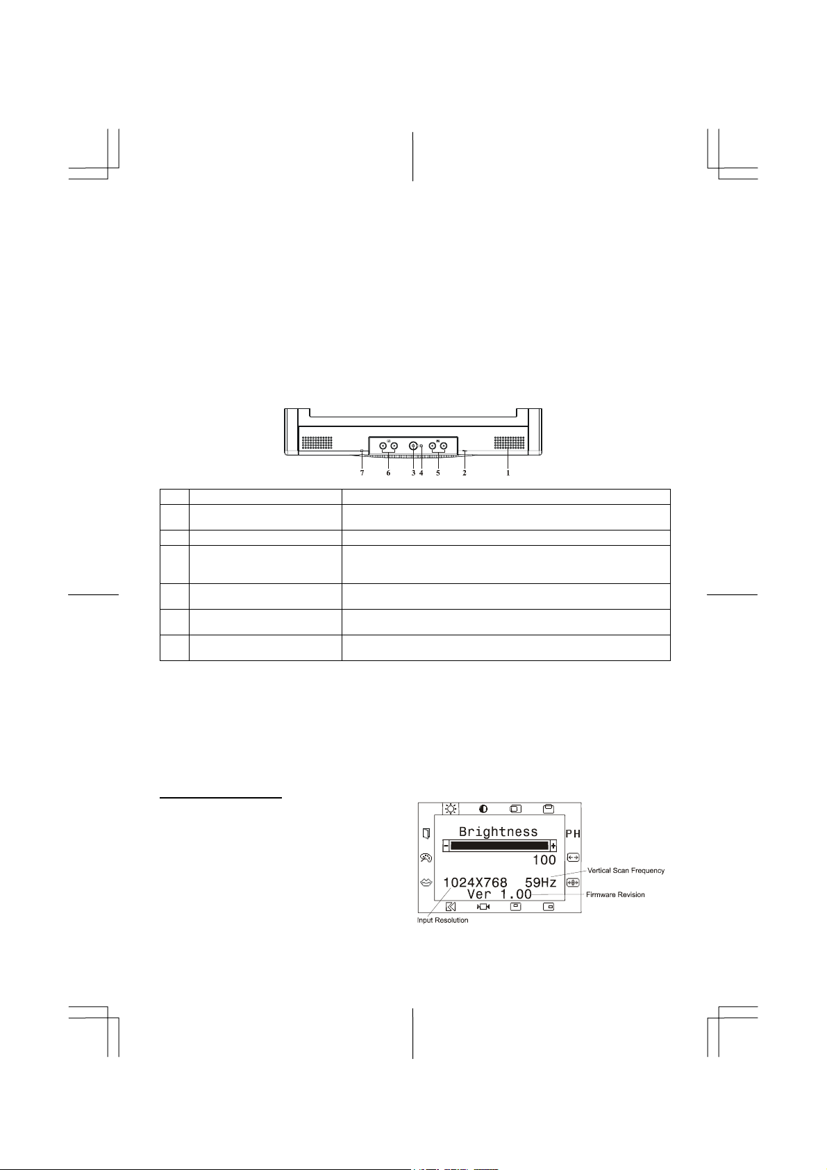
A brief description and the location of all LCD Monitor function controls and indicators:
Stereo Speakers
1
Speaker Volume Control
2
DC Power Switch
3
DC Power-On Indicator
4
Function Select Buttons
5
Adjustment Control
6
Buttons
External Headphone
7
Jack
Figure 2-1
PC Audio Stereo output.
Increase Volume - Turn the knob clock wise.
Decrease Volume - Turn the knob counter clock wise.
Press the power switch to switch the monitor ON/OFF.
LED lights Green color --- Power is ON.
LED lights Yellow --- Monitor is in "Power Saving Mode".
LED is off --- Power is OFF.
Press either left or right control button for OSD (On Screen
Display) menu selection.
Press the left button to decrease the OSD setting and press the
right button to increase the OSD setting.
The monitor speakers will be disabled when using an external
headphone or external speakers.
Adjusting the Monitor's Display
This LCD monitor features an "Intellectual-AUTO" function, which stores up to 16 user's settings.
When new settings are made, this function will check whether this setting has been Auto-adjusted
before. If so, this monitor will use those settings. If not, this monitor will automatically start
Auto-adjustment to obtain the best viewing settings. The auto-adjustment process takes 3 ~ 5
seconds to complete during which a "Auto Adjusting..." message will be shown on your screen.
The monitor has four function control keys among the functions shown on the OSD menu, designed
to create an easy user-viewing environment.
OSD Function Menu
To access OSD Main menu, simply press one of
the Function Select control buttons, and the
menu diagram will pop up on the screen as
shown on Fig. 2-2:
Continue pressing the Function Select buttons to
scroll through the entire menu items ,then press
Adjustment Control buttons to adjust content of
selected item.
Attention:Firmware revision may have been updated into a latest version while the version number shown
on all OSD menus in this manual will stay as Ver. 1.00.
4
Page 5
AL722 User’s Manual
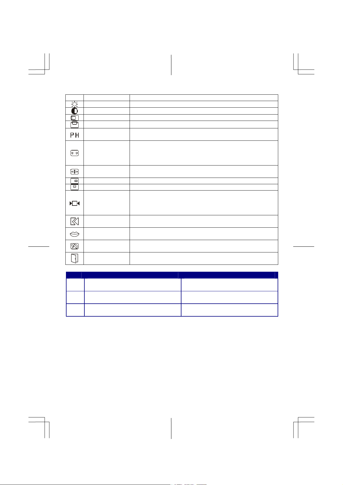
Function Description
Icon Function Function Description
BRIGHTNESS 101 scales of brightness are available to choose from 0 to 100.
CONTRAST 101 scales of contrast are available to choose from 0 to 100.
H-POSITION This function let's you adjust the display's horizontal position.
V-POSITION This function let's you adjust the display's vertical position.
PHASE
CLOCK
AUTO ADJUST
OSD H-POSITION This function moves the OSD menu window horizontally.
OSD V-POSITION This function moves the OSD menu window vertically
GRAPHIC TEXT
RECALL
LANGUAGE
COLOR TEMP
SAVE + EXIT
Icon Function Description
CIE coordinated Color Temperature of
9300
9300°K
CIE coordinated Color Temperature of
6500
6500°K
Three colors (Red, Green, Blue) can be
User
adjusted from the OSD menu
A total of 32 scales (0 to 31) are available to adjust the focus and
clarity of the display.
This function carries a frequency-tracking feature that offers the
user to have better stability and clarity. Increasing Clock value can
be up to +64 scales. The number of decreasing Clock (minus) is
depending on the input timing.
This function will adjust the display size automatically to fit full
screen.
This function is to choose a display that allows maximum graphics
text quality. The resolution selection can either be 640 x 400 or 720
x 400. Please refer to Chapter 3 “ Standard Timing” Table for of
different timing modes.
The recall function will return all adjusted parameters to
factory-preset values.
Five OSD language options are available:
English, German, French, Spanish, and Italian
Push the (+/-) button to select a different color temperature. Please
see the diagram below for function and description.
Saves the values of this setting and exits the OSD
menu function
Sets the CIE coordinate color temperature
to 9300°K
Sets the CIE coordinate color temperature
to 6500°K
Sets the settings to a by user defined CIE
Temperature.
5
Page 6
Chapter 3 Technical Information
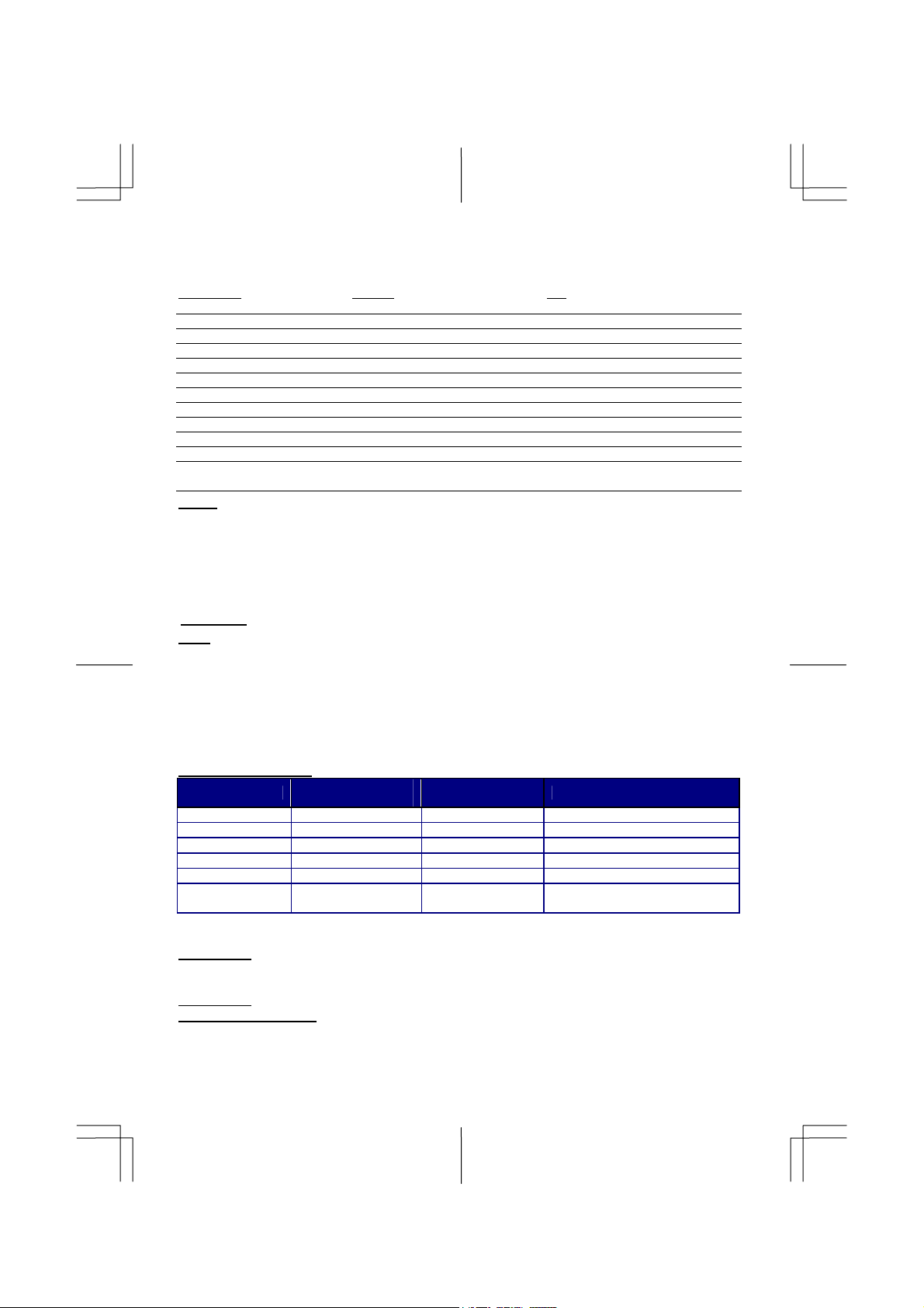
Specifications
LCD Panel HYDIS AU
Size 17.0" (43 cm) 17.0" (43 cm)
Display Type Active matrix color TFT LCD Active matrix color TFT LCD
Resolution 1280 x 1024 1280 x 1024
Display Dot 1280 x (RGB) x 1024 1280 x (RGB) x 1024
Display Area (mm) 337.92 x 270.34 (HxV) 337.92 x 270.34 (HxV)
Display Color 16.7M 16.7M
Brightness 250 cd/m2 (typical) 250 cd/m2 (typical)
Contrast Ratio 400: 1 (typical) 400: 1 (typical)
Response Time 25ms (typical) (25+15) ms (typical)
Lamp Voltage 800 Vrms (typical) 720 Vrms (typical)
Lamp Current 6.0 mA rms. (typical) 6.0 mA rms. (typical)
Viewing Angle Vertical: -60° ~ +70° Vertical: -70° ~ +70°
Horizontal: -75° ~ +75° Horizontal: -75° ~ +75°
Video
Input Signal
Input Impedance
Polarity
Amplitude
Multi-mode Supported
Control
Power On/Off switch with LED indicator
OSD
Brightness
Contrast
Horizontal Position
Vertical Position
Phase
Clock
Display Mode Setup
Power Management
Mode
On 54W maximum 240 VAC Green
Standby** 5W maximum 240 VAC Yellow
Suspend** 5W maximum 240 VAC Yellow
Off** 5W maximum 240 VAC Yellow
DC Power Off 5W maximum 240 VAC Dark
Disconnected 5W maximum 240 VAC
* Meeting VESA DPMS requirements measured from AC Input end of AC adapter.
** The status of standby, suspend and off don't include the power consumption of the audio components.
Sync Input
Signal Separate TTL compatible horizontal and vertical synchronization
Polarity Positive and negative
Plug & Play
Supports VESA DDC1 and DDC2B functions
External Connection
Power Input (DC input) +12 VDC / 5A min. input through AC/DC adapter
Video Cable 1.5M with 15-pin D-sub connector
Audio Cable 1.5M with Stereo Jack
Analog RGB 0.7Vp-p
75 Ohm ± 2%
Positive
0 - 0.7 ± 0.05 Vp
Horizontal Frequency: 24 ~ 80 KHz
Vertical Frequency: 56 ~ 75 Hz
Digital
Digital
Digital
Digital
Digital
Digital
Use EEPROM to save settings in memory
Power
Consumption*
AC Input LED Color
Yellow: Standby, Suspend, Off
Dark: DC Power off
6
Page 7
AL722 User’s Manual
Environment
Operating Condition:
Temperature
Relative Humidity
5°C to 40°C/41°F to 104°F
20% to 80% (non-condensing)
Storage Condition:
Temperature
Relative Humidity
-20°C to 60° C/-4°F to140° F
5% to 85% (non-condensing)
Power Supply (AC Adapter)
Input Voltage Single phase, 100 ~ 240VAC, 50 / 60 Hz
Input Current 1.5 A maximum
Size and Weight
Dimensions 424 (W) x 436 (H) x 178 (D) mm
Net Weight 6.5 ± 0.3 kg
Gross Weight 8.7 ± 0.3 kg
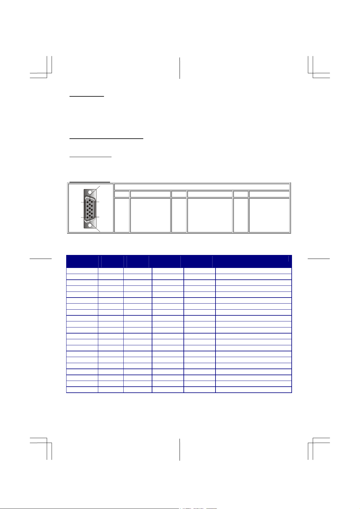
Pin Assignment
6
Signal
PIN Description PIN Description PIN Description
1
5
11
15
10
1
2
3
4
5
Red
Green
Blue
NC
Digital GND
6
7
8
9
10
Red Rtn
Green Rtn
Blue Rtn
+5V
Digital GND
11
12
13
14
15
NC
SDA
H. Sync.
V. Sync.
SCL
Standard Timing Table
If the selected timing is NOT included in table below, this LCD monitor will use the most suitable
available timing.
Resolution H. Freq.
(KHz)
640 x 350 31.469 70.087 25.175 +/- VGA-350
640 x 400 24.83 56.42 21.05 -/- NEC PC 9801
640 x 400 31.469 70.087 25.175 -/+ VGA-400-GRAPH
640 x 400 31.5 70.15 25.197 -/- NEC PC9821
640 x 480 31.469 59.940 25.175 -/- VGA 480
640 x 480 35.000 66.670 30.240 -/- APPLE MAC – 480
640 x 480 37.861 72.809 31.500 -/- VESA – 480 – 72Hz
640 x 480 37.500 75.000 31.500 -/- VESA – 480 – 75Hz
720 x 400 31.469 70.087 28.322 -/+ VESA-400-TEXT
832 x 624 49.725 74.550 57.283 -/- APPLE-MAC-800
800 x 600 35.156 56.250 36.000 +/+ SVGA
800 x 600 37.879 60.317 40.000 +/+ VESA-600-60 Hz
800 x 600 48.077 72.188 50.000 +/+ VESA-600-72 Hz
800 x 600 46.875 75.000 49.500 +/+ VESA-600-75 Hz
1024 x 768 48.363 60.004 65.000 -/- XGA
1024 x 768 53.964 66.132 71.664 +/+ COMPAQ-XGA
1024 x 768 56.476 70.069 75.000 -/- VESA-600-70 Hz
1024 x 768 60.023 75.029 78.750 +/+ VESA-768-75 Hz
1024 x 768 60.04 75.02 80.00 -/- APPLE MAC-768
1280 x 1024 63.981 60.020 108 +/+ SXGA
1280 x 1024 79.976 75.025 135 +/+ SXGA
Note: When the input display mode is not 1280 x 1024, the image is smoothly expanded to 1280 x 1024
dots with the PW164A scaling engine. After expansion from 640x350, 640x400, 640x480, 720x400,
832x624, 800x600, and 1024x768 resolution, the text may look not so sharp, and the Graphics may look
not so proportional.
V. Freq.
(Hz)
Pixel Freq.
(MHz)
H/V Sync.
Polarity
Mode
7
Page 8
Troubleshooting
This LCD Monitor has pre-adjusted using factory standard VGA timings. Due to the output timing
differences among various VGA cards in the market, users may initially experience an unstable or
unclear display whenever a new display mode or new VGA card is selected.
Attention
This LCD Monitor Supports Multiple VGA Modes.
Refer to the Standard Timing Table for a listing of modes supported by this LCD Monitor.
PROBLEM Picture is unclear and unstable
The picture is unclear and unstable, please perform the following steps :
1. Enter PC to “Shut Down Windows” status while you’re in MS-Windows environment.
2. Check the screen to see if there’s any black vertical stripes appear. If there are, take advantage of
the “Clock” function in OSD menu and adjust (by increment or decrement numbers) until those
bars disappear.
3. Move to “Phase” function in OSD menu again and adjust the monitor screen to its most clear
display.
4. Click “No” on “Shut Down Windows” and back to the normal PC operating environment.
PROBLEM There is no picture on LCD Monitor
If there’s no picture on the LCD Monitor, please perform the following steps:
1. Make sure the power indicator on the LCD Monitor is ON, all connections are secured, and the
system is running on the correct timing. Refer to Chapter 3 for information on timing.
2. Turn off the LCD Monitor and then turn it back on again. If there is still no picture, press the
Adjustment Control button several times.
3. If step 2 doesn’t work, connect your PC system to another external CRT. If your PC system
Functions properly with a CRT Monitor but it does not function with the LCD Monitor, the
output timing of the VGA card may be out of the LCD’s synchronous range. Please change to
an alternative mode listed in the Standard Timing Table or replace the VGA card, and then repeat
steps 1 and 2.
PROBLEM There is no picture on LCD Monitor
If you have chosen an output timing that is outside of the LCD Monitor’s synchronous range
(Horizontal: 24 ~ 80 KHz and Vertical: 56 ~ 75 Hz), the OSD will display a “Out of Range”
message. Choose a mode that is supported by your LCD Monitor.
Also, if the signal cable is not connected to LCD monitor at all or properly, the monitor screen will
display a message “No Input Signal”.
8
 Loading...