

Page 1

AcerBasic
User’s Guide
Page 2

Copyright
Copyright © 1997 by Acer Incorporate d. All rights reserved. No
part of this publication may be reproduced, transmitted,
transcribed, stored in a retrieval system, or translated into any
language or computer language, in any form or by any means,
electronic, mechanical, magnetic, optical, chemical, manual or
otherwise, without the prior written permission of Acer
Incorporated.
Disclaimer
Acer Incorporated makes no representations or warranties, either
expressed or implied, with respect to the contents hereof and
specifically disclaims any warranties, merchantability or fitness
for any particular purpose. Any Acer Incorporated software
described in this manual is sold or licensed “as is”. Should the
programs prove defective following their purchase, the buyer (and
not Acer Incorporated, its distributor, or its dealer) assumes the
entire cost of all necessary servicing, re pair, and any incidental or
consequential damages resulting from any defect in the software.
Further, Acer Incorporated reserves the right to revise this
publication and to make changes from time to time in the co ntents
hereof without obligation of Acer Incorporate d to notif y any p erso n
of such revision or changes.
Acer is a registered trademark of Acer Incorporated. Microsoft and Windows 95
are registered trademarks of Microsoft Corporation. IBM is a registered
trademark and IRConnect is a trademark of IBM Corpor ation. Intel and Pe ntium
are registered trademarks of Intel Corporation. Other brand and product names
are trademarks and/or registered trademarks of their respective companies.
ii
Page 3

IMPORTANT SAFETY INSTRUCTIONS
1. Read these instructio ns care fully. Save the se i nstructio ns fo r future
reference.
2. Follow all warnings and instructions marked on the product.
3. Unplug this product from the wall outlet before cleaning. Do not use
liquid cleaners or aerosol cleaners. Use a damp cloth for cleaning.
4. Do not use this product near water.
5. Do not place this product on an unstable cart, stand, or table. The
product may fall, causing serious damage to the product.
6. Slots and openings in the cabinet and the back or bottom are
provided for ventilation; to ensure reliable operation of the product
and to protect it from overheating, these openings must not be
blocked or covered. The openings should never be blocked by placing
the product on a bed, sofa, rug, or other similar surface. This
product should never be placed near or over a radiator or heat
register, or in a built-in installation unless proper ventilation is
provided.
7. This product should be operated from the type of power indicated on
the marking label. If you are not sure of the type of power available,
consult your dealer or local power company.
8. Do not allow anyth ing to rest on the power cord. Do not l ocate this
product where persons will walk on the cord.
9. If an extension cord is use d with this product, make sure that the
total ampere rating of the equipment plugged into the extension
cord does not exceed the extension cord ampere rating. Also, make
sure that the total rating o f all pro ducts pl ugged i nto the wal l o utlet
does not exceed the fuse rating.
iii
Page 4

10. Never push objects of any kind into this product through cabinet
slots as they may touch dangerous voltage points or short out parts
that could result in a fire or electric shock. Never spill liquid of any
kind on the product.
11. Do not attempt to service this product yourself, as opening or
removing covers may expose you to dangerous voltage points or
other risks. Refer a ll servicing to qualified service personnel.
12. Unplug this product from the wall outlet and refer servicing to
qualified service personnel under the following conditions:
a. When the power cord or plug is damaged or frayed
b. If liquid has been spilled into the product
c. If the product has been exposed to rain or water
d. If the product does not operate normally when the operating
instructions are followed. Adjust only those controls that are
covered by the operating instructions since improper
adjustment of other controls may result in damage and will
often require extensive work by a qualified technician to
restore the product to normal condition.
e. If the product has been dropped or the cabinet has been
damaged
f. If the product exhibits a distinct change in performance,
indicating a need for service
13. Replace battery with the same type as the product's battery we
recommend. Use of another battery may present a risk of fire or
explosion. Refer battery replacement to a qualified serviceman.
14. Warning! Battery may explode if not handled properly. Do not
disassemble or dispose of in fire. Keep away from children and
dispose of used battery promptly.
15. Use only the pro per type of power s upply cord set (provided in your
accessories box) for this unit. It should be a detachable type: UL
listed/CSA certified, type SVT, rated 7A 125V minimum, VDE
approved or its equivalent. Maximum length is 15 feet (4.6 meters).
iv
Page 5

Caution on Lithium Batteries
CAUTION
Danger of explosion if battery is incorrectly replaced. Replace only with the same
or equivalent type recommended by the manufacturer. Discard used batteries
according to the manufacturer’s instructions.
ADVARSEL!
Lithiumbatteri - Eksplosionsfare ved fejlagtig håndtering. Udskiftning må kun
ske med batteri af samme fabrikat og type. Léver det brugte batteri tilbage til
leverandøren.
ADVARSEL
Eksplosjonsfare ved feilaktig skifte av batteri. Benytt samme batteritype eller en
tilsvarende type anbefalt av apparatfabrikanten. Brukte batterier kasseres i
henhold til fabrikantens instruksjoner.
VARNING
Explosionsfara vid felaktigt batteribyte. Anvãnd samma batterityp eller en
ekvivalent typ som rekommenderas av apparattillverkaren. Kassera anvãnt
batteri enligt fabrikantens instruktion.
VAROITUS
Päristo voi räjähtää, jos se on virheellisesti asennettu. Vaihda paristo ainoastaan
laitevalmistajan suosittelemaan tyyppiin. Hävitä käytetty paristo valmistajan
ohjeiden mukaisesti.
VORSICHT!
Explosionsgefahr bei unsachgemäßen Austausch der Batterie Ersatz nur durch
denselben oder einem vom Hersteller empfohlenem ähnlichen Typ. Entsorgung
gebrauchter Batterien nach Angaben des Herstellers.
v
Page 6

FCC Class B Radio Frequency Interference Statement
Note:
This equipment has been tested and found to comply with the
limits for a Class B digital device, pursuant to Part 15 of FCC
Rules. These limits are designed to provide reasonable p rotection
against harmful interference in a residential installation. This
equipment generates, uses, and can radiate radio frequency
energy and, if not installed and used in accordance with the
instructions, may cause harmful interference to radio
communications. However, there is no guarantee that
interference will not occur in a particular installation. If this
equipment does cause harmful interference to radio or television
reception, which can be determined by turning the equipment off
and on, the user is encouraged to try to correct the interference by
one or more of the following measures:
1. Reorient or relocate the receiving antenna.
2. Increase the separation between the equipment and receiver.
3. Connect the equipment into an outlet on a circuit different
from that to which the receiver is connected.
4. Consult the dealer or an experienced radio/television
technician for help.
Notice 1:
The changes or modifications not expressly approved by the party
responsible for compliance could void the user's authority to
operate the equipment.
Notice 2:
Shielded interface cables, if any, must be used in order to co mply
with the emission limits.
vi
Page 7

Canadian Department of Communications Regulatory Statement
This digital apparatus does not exceed Class B limits for radio
noise emissions from digital apparatus set out in the Radio
Interference Regulations of the Canadian Department of
Communications.
Le présent appareil numérique n'émet pas de bruits radioélectriques dépassant les limites applicables aux appareils
numériques de la classe B prescrites dans le Réglement sur le
brouillage radioélectrique édicté par le ministère des
Communications du Canada.
Laser Compliance
The CD-ROM drive in the AcerBasic is a laser product. The CDROM drive’s classification label (shown below) is located on the top
of the drive.
CLASS 1 LASER PRODUCT
APPAREIL A LASER DE CLASSE 1
PRODUIT LASER
LUOKAN 1 LASERLAITE
LASER KLASSE 1
PRODUCTO LÁSER DE LA CLASE I
CAUTION:
INVISIBLE LASER RADIATION WHEN
OPEN. AVOID EXPOSURE TO BEAM
ATTENTION:
RADIATION DU FAISCEAU LASER
INVISIBLE EN CAS D’OUVERTURE.
EVITTER TOUTE EXPOSITION AUX
RAYONS.
VORSICHT:
UNSICHTBARE LASERSTRAHLUNG,
WENN ABDECKUNG GEÖFFN ET
NICHT DEM STRAHLL AUSSETZEN
ADVERTENCIA:
RADIACIÓN LÁSER INVISIBLE AL
SER ABIERTO. EVITE EXPONERSE A
LOS RAYOS.
vii
Page 8

Congratulations on your purchase of the AcerBasic personal
...............................
................................
....................
..........
.....
................................
................................
.....
................................
................................
.........................
................................
................................
...........
................................
................................
............
................................
.................
................................
................................
.............
................................
................................
.......
................................
..............................
................................
.............................
................................
................................
....................
................................
................................
......................
.......................
................................
................................
.....
..........................
................................
..............
................................
................................
..
................................
................................
.........
................................
................................
.....
................................
................................
................
computer. Compact in size, not in features, the AcerBasic
personal computer opens a window of information to your
home or office. We hope you enjoy your AcerBasic personal
computer as much as we enjoyed designing and making it
for you.
This user’s guide quickly guides you in setting up and using
your AcerBasic personal computer.
Contents
IMPORTANT SAFETY INSTRUCTIONS
Caution on Lithium Batteries
FCC Class B Radio Frequency Interference Statement
Canadian Department of Communications Regulatory Statement
Laser Compliance
Unpacking
Standard Items
Optional Items
Getting to Know your AcerBasic
Basic Features
Optional Features
Setting Up the AcerBas ic
Locating the Connectors
Front
Rear
Finding a Suitable Area to Place the AcerBasic
Basic Connections
Connecting to a Television or a Monitor
Connecting the Power Cord
Connecting Options
Phone Line
Network Line
Printer
iii
v
vi
vii
vii
1
1
2
3
3
5
6
6
6
8
9
10
10
11
12
12
13
13
viii
Page 9

Audio and Game Devices
................................
..................
................................
............................
................................
................................
.
...........................
................................
..................
................................
................................
.....
................................
........................
................................
..................
................................
.......................
................................
...................
.............................
..............................
................................
........................
................................
..
.......................
................................
................................
....
................................
................................
.
................................
..........................
................................
......
................................
.............................
................................
................................
...................
................................
................................
...................
................................
..............................
................................
................................
.
................................
................................
...................
................................
........................
................................
.....................
................................
................................
...
................................
................................
.
................................
................................
.........
................................
................................
....
................................
...................
................................
..................
................................
................................
................................
................................
.............
................................
................................
.................
External Keyboard
External Mouse
Video Cassette Recorder or Camcorder
Computer Video Camera
14
16
17
18
18
Using the AcerBasic
Turning on the Computer
Using the Wireless Keyboard
Installing the Battery
Using the Floppy Disk Drive
Guidelines on Floppy Dis k Drive Use
Inserting and Ejecting a Floppy Disk
Using the CD-ROM Drive
Guidelines on CD-ROM Drive Use
Inserting and Removing a CD-ROM Disc
Setting Passwords
Setup Password
Power On Password
Communicating Between AcerBasics
Transferring Files
Maintenance
Getting Help
Accessing Online Help
Getting Help Online
Setup Utility
BIOS Utility Main Screen
Basic System Configuration
Date and Time
Diskette Drives
IDE Drives
Total Memory
Enhanced IDE Features
Large Memory Support Mode
Num Lock After Boot
Memory Test
Quiet Boot
19
19
20
20
21
21
22
24
24
25
27
27
30
31
32
33
34
34
34
35
35
37
38
39
40
42
42
44
44
44
44
ix
Page 10

Configuration Table
................................
................................
..
................................
.............
................................
............
................................
................................
..
................................
..............
................................
..
................................
.........................
................................
....................
................................
................
................................
..........................
................................
....................
................................
.......................
................................
................................
........
................................
............................
................................
........
................................
.........
................................
................................
.
................................
..........................
................................
...............
................................
................................
................................
............................
................................
................................
....
................................
...............................
................................
...........................
................................
................................
.
................................
............
................................
...........................
................................
.........................
................................
....................
Advanced System Configuration
Internal Cache (CPU Cache)
External Cache
ECC/Parity Mode Selection
Memory at 15-16 MB Reserved for
USB Host Controller
Power Saving Configuration
Power Management Mode
Monitored Activities
QuickStart State Timer
Point Device Location
System Security
Disk Drive Control
Onboard Communication Ports
Onboard PS/2 Mouse (IRQ 12)
Setup Password
Power On Password
PCI/PnP System Configuration
PCI IRQ Setting
PCI Slots (1 and 2)
Onboard VGA
PCI IRQ Sharing
VGA Palette Snoop
Plug & Play OS
Reset Resources Assignment
Onboard LAN Chip
Onboard Audio Chip
Load Setup Default Settings
45
46
46
47
47
47
47
48
48
50
50
50
51
51
53
56
57
57
58
58
59
59
59
60
60
61
61
61
62
x
Page 11
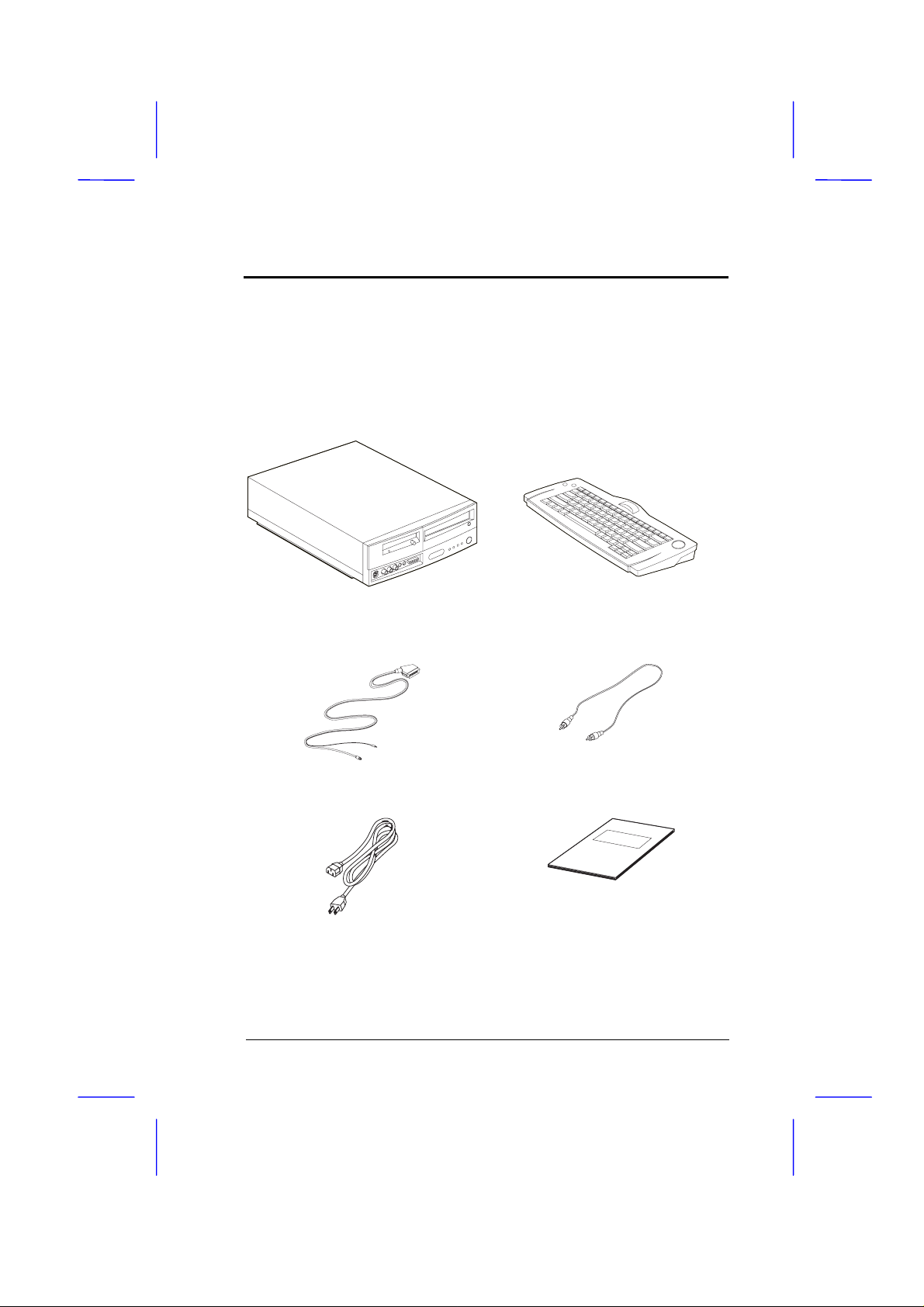
Unpacking
The AcerBasic personal computer package contains the
following items. Carefully unpack each item and set aside.
Standard Items
❍ AcerBasic personal
computer
❍ SCART Euro-AV cable ❍ Audio and video cables
❍ Power cord ❍ User’s guide and
❍ Wireless keyboard
miscellaneous items
User’s Guide 1
Page 12

Unpacking
Optional Items
❍
Remote control
❍
Computer video camera kit
The items in your package may differ slightly.
2 User’s Guide
Page 13

Getting to Know your AcerBasic
*
The AcerBasic series personal computer has common
features listed below:
Basic Features
❍ High-performance central processing unit (CPU)
A fast core (consisting of the CPU and chipsets*) allows
your computer to process information and data fast.
❍ High-speed memory
Standard memory configuration is 16 megabytes (MB) of
fast EDO (Extended Data Out) or fast page RAM
(Random Access Memory). These memory types give you
true value, balancing price and performance.
❍ High-performance video
The graphics adapter with 2MB of video memory
outputs high-resolution, high-speed graphics onto your
television or monitor. 3D graphics support also turn
your AcerBasic into a gaming machine.
❍ High-capacity storage mediums
One high-capacity hard disk drive
•
One 3.5-inch, 1.44MB floppy disk drive
•
One high-speed CD-ROM drive
•
Chipsets are sets of microprocessors that perform specific functions.
User’s Guide 3
Page 14

Getting to Know your AcerBasic
❍ High-speed connectivity
Whether you need to get connected via modem or
network, this computer has it. Its built-in 33.6 kilobits
per second (Kbps) modem connects to a phone line; its
built-in Ethernet (10BaseT) jack connects to a network.
See page 12.
❍ Peripheral connectivity
Located at the front and rear of the computer are a host
of connectors for a large variety of peripherals —
printer, mouse, keyboard, microphone, speakers, joystick
just to name a few. See “Setting Up the AcerBasic” on
page 6.
❍ “User-Friendly” software
The bundled software helps you explore a world of
information. Refer to the applications guide for details.
❍ Security features
Security features include passwords for protecting your
computer from unauthorized access. See page 27.
4 User’s Guide
Page 15

Getting to Know your AcerBasic
Optional Features
Options include:
❍ Hardware upgrades
Additional memory
•
Higher-capacity hard disk
•
Higher-speed CD-ROM drive
•
DVD-ROM drive
•
MPEG-II capability
•
❍ Hardware options
Remote control
•
Computer video camera kit
•
External monitor
•
External keyboard
•
External mouse
•
Network hubs
•
USB devices
•
❍ Software options
Please contact your dealer or reseller for the options
available in your region.
User’s Guide 5
Page 16
Setting Up the AcerBasic
This section describes the things to consider when setting
up your AcerBasic.
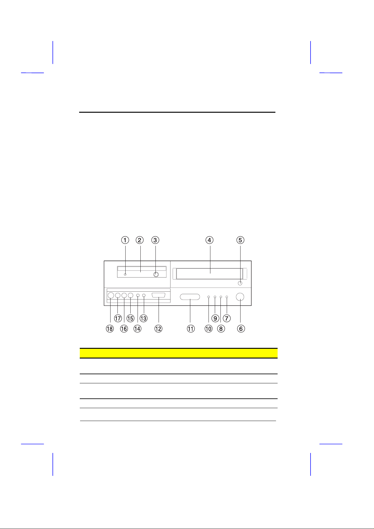
Locating the Connectors
Most of the connectors on the computer are found at the
rear of the unit. A few connectors are found on the front for
easy access. Let’s take a look at the front and rear of the
unit before we make the connections.
Front
# Item Description
1 Floppy disk drive activity
indicator
2 Floppy disk drive Accepts 3.5-inch, 1.44MB diskette
3 Floppy disk drive eject
button
4 CD-ROM drive Accepts a CD-ROM disc
Lights up when the floppy disk drive is
being accessed
Ejects the diskette from the floppy disk
drive
6 User’s Guide
Page 17

Setting Up the AcerBasic
*
# Item Description
5 CD-ROM drive open/close
button
6 On/sleep button Turns the computer on and puts the
7 Power/suspend indicator Lights green when on; lights orange
8 Hard disk/message
indicator
9 Network active indicator Flashes when your computer is
10 Network link indicator Lights when the computer is connected
11 Infrared receiver Receives input from the wireless
12 Game/MIDI port Connects a joystick, game device or
13 Microphone jack Connects a microphone
14 Earphone/headphone jack Connects an earphone or headphone
15 VCR/camcorder audio
input jack (right)
16 VCR/camcorder audio
input jack (left)
17 VCR/camcorder video
input jack
18 S-video input Connects to the S-video input of a VCR
Opens and closes the CD-ROM drive
computer to sleep
when in suspend mode
Flashes when your hard disk drive is in
use
communicating with the network
to a network
keyboard or remote control
Allows you to transfer data or files with
another AcerBasic computer
MIDI device
Connects to the right audio input of a
VCR or camcorder
Connects to the left audio input of a
VCR or camcorder
Connects to the video input of a VCR or
camcorder
or camcorder
*
Your computer enters suspend mode when the suspend timer times out (see
page 50). You can also put the computer in suspend mode by selecting the
Suspend…command from the Start menu.
User’s Guide 7
Page 18
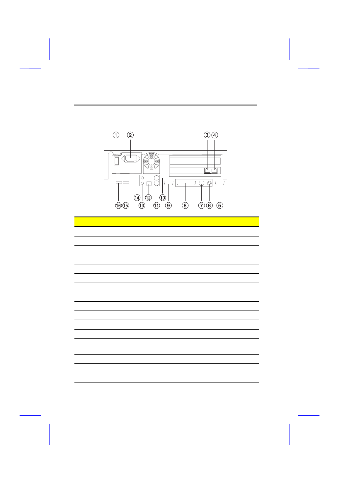
Setting Up the AcerBasic
Rear
# Item Description
1 On/off switch Turns power on and off
2 Power cord socket Connects a power cord
3 Phone set jack Connects a telephone set
4 Phone line jack Connects a phone line
5 External CRT port Connects an external monitor
6 Video output jack Connects to the video input of a television
7 S-video output jack Connects to the S-video input of a television
8 Parallel port Connects a printer or other parallel device
9 Serial port Connect a serial mouse or other serial device
10 PS/2 mouse port Connects a PS/2 mouse
11 PS/2 keyboard port Connects a PS/2 keyboard
12 Network jack Connects a network line (Ethernet)
13 Audio output jack Connects to speakers or other audio output
devices
14 Audio input jack Connects a audio input device
15 USB port 2 Connects a USB device
16 USB port 1 Connects a USB device
8 User’s Guide
Page 19
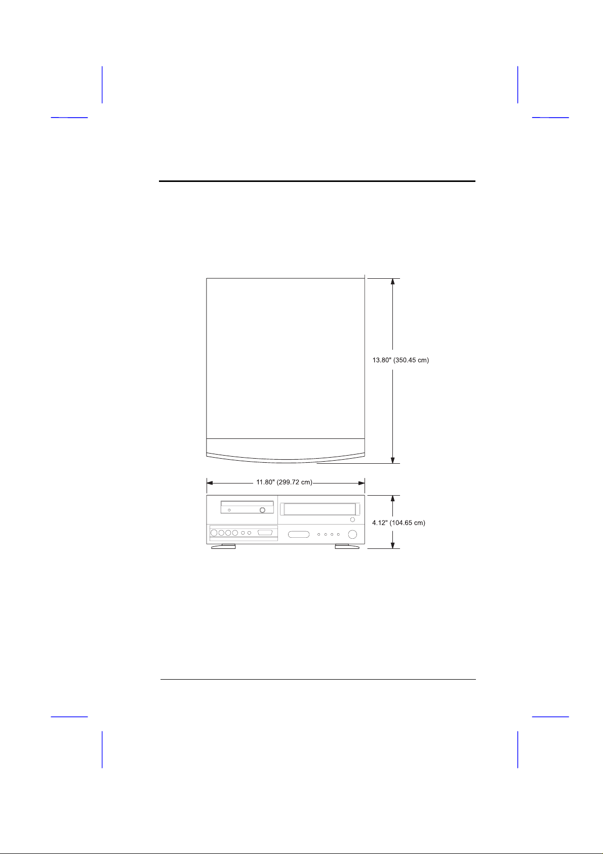
Setting Up the AcerBasic
Finding a Suitable Area to Place the AcerBasic
The AcerBasic has the following dimensions.
Locate a suitable area to place the AcerBasic. Allow ample
space on all sides of the unit for cords and cable connections.
The AcerBasic should also be placed near the devices you
will connect to it.
User’s Guide 9
Page 20
Setting Up the AcerBasic
Basic Connections
These are the basic connections you need to get your
AcerBasic up and going. You can also connect options like a
printer or the phone line, described in pages 12 to 17.
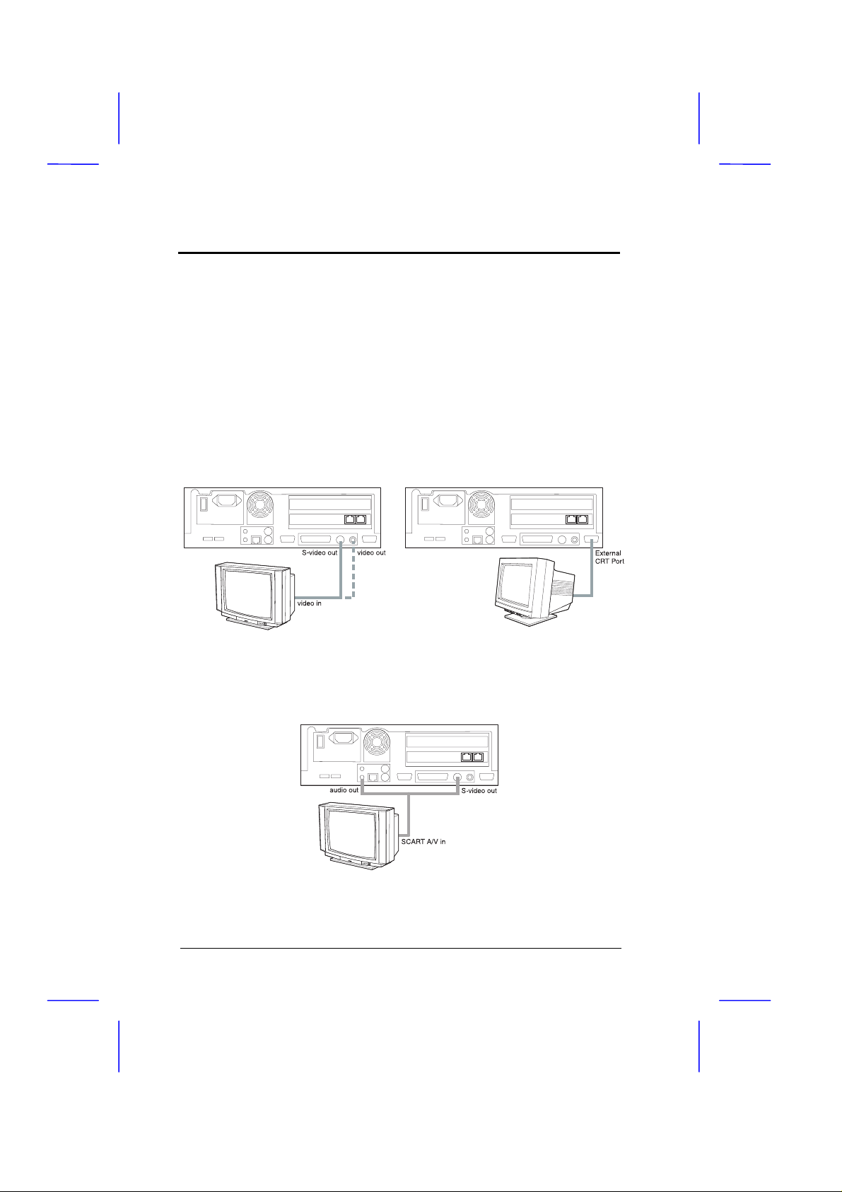
Connecting to a Television or a Monitor
First you need to connect an output device to the computer
which can either be a television unit or a computer monitor.
Television Unit Computer Monitor
If your television uses a SCART interface, use the included
SCART cable to connect your television set to the computer.
10 User’s Guide
Page 21
Setting Up the AcerBasic
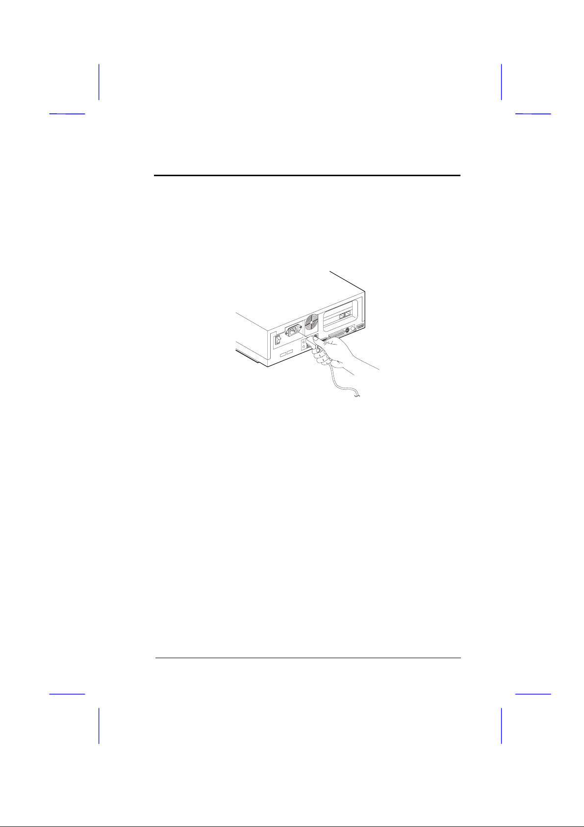
Connecting the Power Cord
Connect the power cord to the power cord socket at the rear
of the unit. Then connect the other end to a properly
ground power outlet.
These basic connections you’ve just made are all you need to
get your AcerBasic up and running. If you need to make
other connections such as a phone line (for connecting to the
Internet) or a printer (for printing documents), read on.
Otherwise, you can jump to page 19.
User’s Guide 11
Page 22
Setting Up the AcerBasic
Connecting Options
Other connections you make to your computer include the
following:
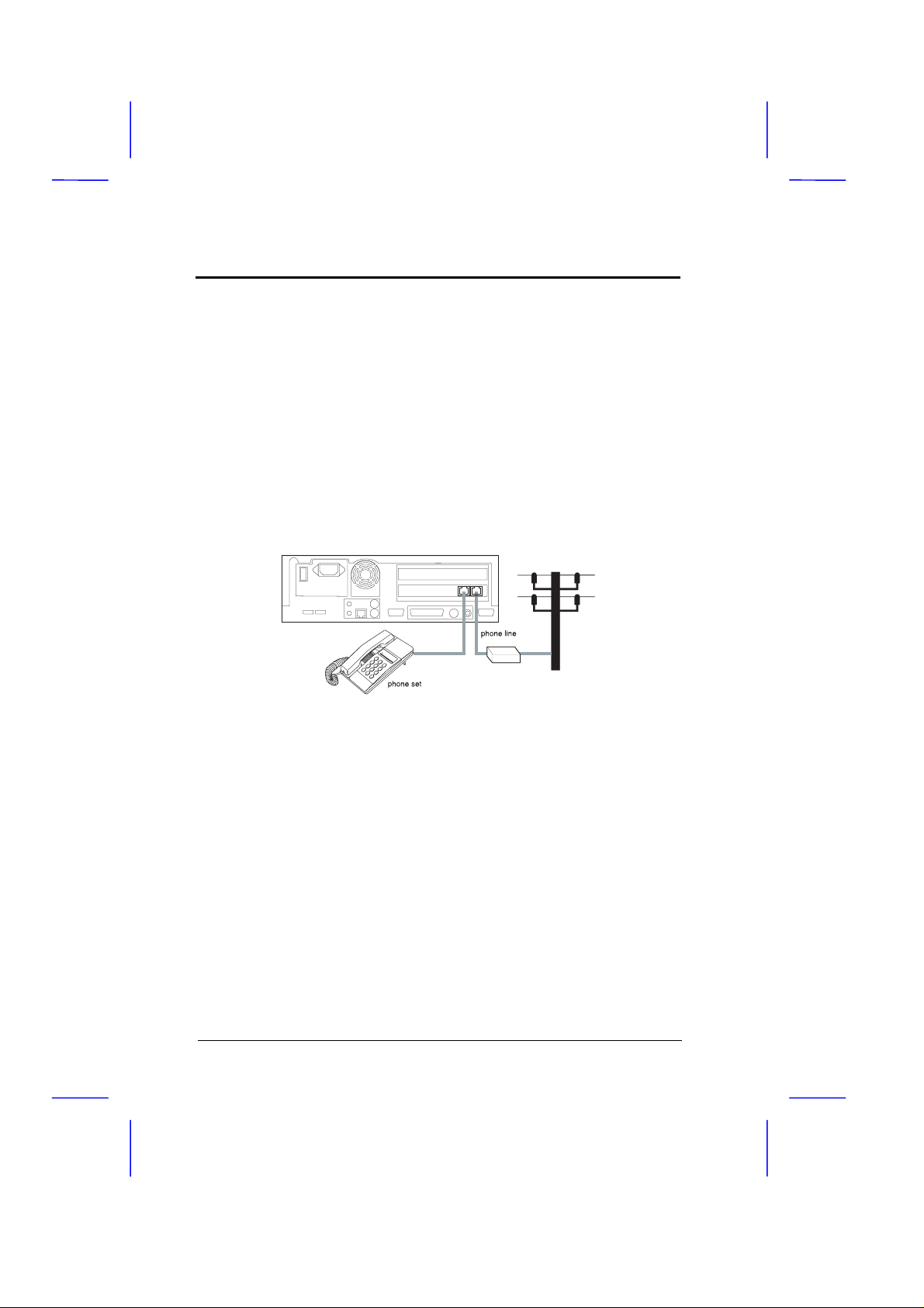
Phone Line
Connecting to the Internet usually requires a modem, which
is built into the AcerBasic. A phone line jack, found at the
rear of the unit, connects to your phone line. You can also
connect a telephone set to the phone set jack.
Your modem has been designed to work with an analog
telephone line like the ones commonly found in your home.
Connecting your modem to a digital phone system or a PBX
(Private Branch Exchange) system, like the ones found in
large establishments and office complexes, can cause
damage to your modem.
Before using the modem, make sure you are connecting an
analog telephone line. Check with the your telephone
company or office where you can connect to an analog line.
12 User’s Guide
Page 23

Setting Up the AcerBasic
Network Line
You can connect the AcerBasic to a network with the builtin 10BaseT (Ethernet) jack found at the rear of the unit.
Computers in most companies are connected on networks to
facilitate the transfer of information.
If you are using the AcerBasic in a networked environment,
contact your system administrator for details.
Printer
A printer allows you to print out documents and other data
from your computer to paper. At the rear of the unit,
connect a parallel printer to the parallel port; or connect a
serial printer to the serial port.
User’s Guide 13
Page 24

Setting Up the AcerBasic
Audio and Game Devices
You can connect various audio and game devices to your
computer. Some of these ports are duplicated in the front of
the unit for easy connection.
At the rear of the unit:
❍ speakers, earphones or headphones connect to the audio
line-out jack
❍ audio input device connects to the audio input jack
14 User’s Guide
Page 25

Setting Up the AcerBasic
At the front of the unit:
❍ earphones or headphones connect to the earphone/
headphone jack
❍ microphone connects to the microphone jack
❍ joystick, game or MIDI device connects to the
game/MIDI port
User’s Guide 15
Page 26

Setting Up the AcerBasic
External Keyboard
You may prefer to use an external keyboard instead of the
wireless keyboard that comes with the AcerBasic. There
are two types of keyboards besides the wireless keyboard
that you can use with the AcerBasic:
❍ USB keyboard connects to any of the two USB ports
❍ PS/2 keyboard connects to the PS/2 keyboard port
These ports are found on the rear of the unit.
16 User’s Guide
Page 27

Setting Up the AcerBasic
External Mouse
The wireless keyboard has a built-in pointing device.
However, you may prefer to use an external mouse instead.
There are three types of mice besides the one built into the
wireless keyboard that you can use with the AcerBasic:
❍ USB mouse connects to any of the two USB ports
❍ PS/2 mouse connects to the PS/2 mouse port
❍ Serial mouse connects to the serial port
These ports are found on the rear of the unit.
User’s Guide 17
Page 28

Setting Up the AcerBasic
*
Video Cassette Recorder or Camcorder
You can also connect a video cassette recorder (VCR) or
camcorder to the unit.
Computer Video Camera
You can also connect a computer video camera to the unit.
Some computer video cameras support an S-video connection.
18 User’s Guide
Page 29

Using the AcerBasic
Turning on the Computer
Follow these steps to turn on your computer:
1. A power switch is located at the rear of the computer, to
the left of the power cord socket. Press the power
switch to the ON (❙) position.
2. Turn on your television or your monitor (the one you
connected to the computer).
3. Press the On/Sleep button at the front of the computer.
The computer starts up and Windows 95 begins loading.
User’s Guide 19
Page 30

Using the AcerBasic
The wireless keyboard uses two
(2) size AA batteries. Flip open
the battery cover to see the
After installing the batteries,
Using the Wireless Keyboard
The wireless keyboard with infrared technology has a builtin pointing device, similar to the ones found in gamepads.
This direction pad functions like a mouse or trackball as it
moves the cursor on the screen.
Move the direction pad in any direction to move the mouse
pointer on the screen. The left and right buttons function
like those on a mouse or trackball.
Installing the Battery
installation diagram.
close the battery cover.
20 User’s Guide
Page 31

Using the AcerBasic
Using the Floppy Disk Drive
The floppy disk drive accepts a 3.5-inch, 1.44MB diskette.
Found in almost all computer systems today, this diskette
type standard allows you to easily transfer files between
your AcerBasic and other computer systems.
Guidelines on Floppy Disk Drive Use
Read through the following guidelines when using the
floppy disk drive:
❍ Always make backup copies of diskettes that contain
important data or program files.
❍ Keep diskettes away from magnetic fields and sources of
heat.
❍ Avoid removing a diskette from a drive when the floppy
drive activity light is on.
❍ When you put a label on a 3.5-inch diskette, make sure
the label is properly attached (flat on the surface) and
within the labelling area (area with slight surface
depression) on the diskette. An improperly attached
label may cause a diskette to get stuck in the drive when
you are inserting or removing it.
User’s Guide 21
Page 32

Using the AcerBasic
❍ Write-protect your diskettes to prevent accidental
erasure. To do this, slide the write-protect tab to the
write-protect position.
Write-protected
Not write-protected
Inserting and Ejecting a Floppy Disk
To insert a floppy disk for use with the AcerBasic, insert the
floppy disk into the floppy disk drive as shown in the figure
below.
22 User’s Guide
Page 33

Using the AcerBasic
To eject a floppy disk, press the floppy disk drive eject
button. Then carefully remove the floppy disk from the
floppy disk drive.
User’s Guide 23
Page 34

Using the AcerBasic
Using the CD-ROM Drive
The CD-ROM drive is capable of high speed data access and
transfer, and can read a variety of CD formats as well as
play your audio compact discs. The compact disc stores as
much as 650MB of information, making it a useful medium
for presenting multimedia-based applications.
Guidelines on CD-ROM Drive Use
Read through the following guidelines before using the CDROM drive:
❍ Do not open the disc tray except when inserting or
removing a disc.
❍ Do not place any item on top of the disc tray. Never
attempt to push down on an opened disc tray.
❍ Always remove the disc from the drive if you are going to
move the AcerBasic.
❍ On discs:
Always handle a disc by its edges. Do not touch the
•
surface of the disc (especially the underside)
Never write on a disc or place a label on the surface
•
of the disc.
Never bend a disc.
•
Do not store a disc in places with high temperature
•
and humidity.
24 User’s Guide
Page 35

Using the AcerBasic
Always store a disc in its case to prevent dust
•
contamination, scratches, bending, and other
damages.
To remove dust or fingerprints, use a clean, soft and
•
dry cloth. Never use fluids like benzene or antistatic fluids. Using fluids of these types may
damage the disc.
Inserting and Removing a CD-ROM Disc
To insert a CD-ROM disc into the CD-ROM drive, the
computer must be ON. Follow these steps:
1. Press the CD-ROM drive open/close button.
The CD-ROM disc tray slides out.
User’s Guide 25
Page 36

Using the AcerBasic
2. Place a CD-ROM disc onto the CD-ROM disc tray.
3. Press the CD-ROM drive open/close button. The CDROM drive tray slides back in.
26 User’s Guide
Page 37

Using the AcerBasic
Setting Passwords
Passwords are a security feature of your computer,
protecting your computer from unauthorized access.
There are two types of passwords you can set:
❍ Setup
❍ Power-on
Do not forget your password!
password, you need to contact your dealer.
If you forget your
Setup Password
The Setup Password prevents unauthorized access to the
BIOS Utility. The BIOS Utility is a setup utility for your
hardware settings. For more information on this utility, see
page 35.
Setting a Password
1. During POST (while the startup logo is being
displayed), press Ctrl-Alt-Esc to enter the BIOS
Utility.
2. Select System Security and press Enter.
3. Highlight the Setup Password parameter and press the
↑ or ↓
key. The password prompt appears:
User’s Guide 27
Page 38

Using the AcerBasic
4. Type a password. The password may consist of up to
seven characters (A-Z, a-z, 0-9).
Be very careful when typing your password
because the characters do not appear on the
screen.
5. Press Enter. A prompt asks you to retype the
password to verify your first entry.
6. Retype the password then press Enter.
After setting the password, the computer automatically
sets the Setup Password parameter to
Present
7. Press Esc to exit the System Security screen and return
to the main menu.
.
8. Press Esc to exit the BIOS Utility. A dialog box
appears asking if you want to save the CMOS data.
Do you want to save CMOS data?
[Yes] [No]
9. Select
to save the changes and reboot the computer.
Yes
The next time you want to enter the BIOS Utility, you must
key-in your Setup password.
28 User’s Guide
Page 39

Using the AcerBasic
Changing or Removing the Setup Password
Should you want to change your setup password, do the
following:
1. During POST (while the startup logo is being
displayed), press Ctrl-Alt-Esc to enter the BIOS
Utility.
2. Select System Security and press Enter.
3. Highlight the Setup Password parameter.
4. Press → or ← to display the password prompt and keyin a new password.
or
to remove the existing
Press → or ← and select
password.
None
5. Press Esc to exit the System Security screen and return
to the main menu.
6. Press Esc to exit the BIOS Utility. A dialog box
appears asking if you want to save the CMOS data.
Do you want to save CMOS data?
[Yes] [No]
7. Select
to save the changes.
Yes
User’s Guide 29
Page 40

Using the AcerBasic
Power On Password
The Power On Password secures your computer against
unauthorized use. Once you set this password, you have to
type it whenever you boot the computer. To set this
password, enter the BIOS Utility, select System Security,
then highlight the Power On Password parameter. Follow
the same procedure as in setting the Setup password.
30 User’s Guide
Page 41

Using the AcerBasic
Communicating Between AcerBasics
You can transfer files between two AcerBasic computers
using the built-in infrared feature and bundled infrared
software.
The two AcerBasic units should be facing each other with a
maximum angle of 15 degrees. When set-up, the two
computers will automatically detect and establish a
connection. The IRConnect (“infrared connect”) icon will
appear on the taskbar, indicating the status of the
connection:
❍
❍
User’s Guide 31
means a successful connection
means no connection
Page 42

Using the AcerBasic
Transferring Files
With a proper connection, you can now transfer files
between the two computers. Follow these steps:
1. Double-click on the Network Neighborhood icon on your
desktop.
Two new items pertaining to the two computers appear
in the list.
2. Double-click on each item to open their contents.
3. Drag and drop files from one computer to the other, and
vice-versa.
You can also access these functions via the IRConnect
software. Simply double-click on the IRConnect taskbar
icon to bring up the window; then access the toolbar or
menu functions.
To set-up the IRConnect software, please refer to the
applications manual for details.
32 User’s Guide
Page 43

Care and Maintenance
This section includes items on care and maintenance of your
computer.
Your computer will serve you well if you take care of it.
This section tells you how to care for the notebook. Also, reread the important safety instructions at the beginning of
this manual.
❍ Do not expose the computer to direct sunlight. Do not
place near sources of heat, such as a radiator or heater.
❍ Do not expose to temperatures below 0ºC (32ºF) or above
50ºC (122ºF).
❍ Do not subject the computer and magnetic media (e.g.,
diskettes) to magnetic fields.
❍ Do not expose the computer to rain or moisture.
❍ Do not spill water on the computer.
❍ Do not insert inappropriate objects into the diskette and
CD-ROM drives. Diskettes, one at a time, go into the
diskette drive; One CD-ROM disc goes on the CD-ROM
drive tray.
❍ Do not subject the computer to heavy shock and
vibration.
❍ Do not expose the computer to dust and dirt.
❍ Do not place items on top of cables; carefully route
cables to and from the computer.
User’s Guide 33
Page 44

Getting Help
This user’s guide provides clear and concise information
about your AcerBasic, so read it thoroughly. Online help is
also especially helpful when using specific applications.
Accessing Online Help
To get help with Windows 95:
1. Click on Start.
2. Click on Help.
To get help with specific applications, refer to the
documentation that came with the application. Most
applications have a Help item on their menu bar that you
can gain access to.
Getting Help Online
If you are connected to the Internet and have World Wide
Web access, visit our homepage (http://www.acer.com/) to
get support and the latest information about our products.
34 User’s Guide
Page 45

Setup Utility
Your computer has a built-in BIOS (Basic Input/Output
System) setup utility. With this utility, you can configure
certain hardware settings for your computer.
Basically, your computer is already correctly
configured for you and you do not need to run this
utility unless you get a Run Setup message.
Run this utility if you want to do any of the following:
❍ Check the configuration of the computer
❍ Change the drive boot sequence
❍ Set or change power-saving options
❍ Set or change resume options
❍ Set, change or remove passwords
BIOS Utility Main Screen
Follow these steps to access this utility:
1. Turn on your computer.
The Startup logo screen shows while the computer is
booting up.
2. When you hear a beep, press Ctrl-Alt-Esc.
User’s Guide 35
Page 46

Setup Utility
The following screen is the main menu of the setup utility.
BIOS Utility
Basic System Configuration
Advanced System Configuration
Power Saving Configuration
System Security
PnP/PCI Syst em Configuration
Load Setup Default Settings
= Move Highlight Bar,
↑↓←→
= Select, Esc = E xit and Reboot
↵
To enter a menu item, use the cursor up/down (↑, ↓) keys to
select the item, then press Enter.
The following sections describe the different sections of this
utility.
The parameters on the screens show default values.
Some values such as hard disk drive and memory
sizes may not be the same as those in your computer.
Grayed-out items on the screens have fixed settings
and are not user-configurable.
36 User’s Guide
Page 47

Setup Utility
Basic System Configuration
Select Basic System Configuration to input configuration
values such as date, time, and disk types.
The following screen shows the Basic System Configuration
menu.
Basic System Configuration Page 1/2
Date ............................................... [05/16/97]
Time ...............................................[03:48:00]
Diskette Drive A ............................. [1.44-MB 3.5-inch]
Diskette Drive B .............................[ None ]
Cylinder Head Sector
IDE Drive 0 (1222 MB).....................[Auto] 2484 16 63
IDE Drive 1 ( 0 MB).................... [Auto] 0 0 0
IDE Drive 2 ( 0 MB).................... [Auto] 0 0 0
IDE Drive 3 ( 0 MB).................... [Auto] 0 0 0
Total Memory .................................. [ 16] MB
= Move Highlight Bar, → ← = Change Setting
↑↓
PgDn/PgUp = Move Screen, F1 = Help, Esc = Exit
The command line at the bottom of the menu tells you how
to highlight items, change settings, and move from one
screen to another.
Press cursor up (↑) or cursor down (↓) on the cursor-edit
keypad to highlight the desired parameter.
Press cursor right (→) or cursor left (←) to select the desired
option for a parameter.
User’s Guide 37
Page 48

Setup Utility
Press the page down key (PgDn) to move to the next page
or the page up key (PgUp) to return to the previous page.
Press the escape key (Esc) to exit the configuration menu.
The following screen shows page 2 of the Basic System
Configuration menu.
Basic System Configuration Page 2/2
Enhanced IDE Features
Hard Disk Block Mode ............................... [Enabled ]
Advanced PIO Mode ................................. [Enabled ]
Hard Disk Size > 504MB ........................... [Enabled ]
Hard Disk 32-Bit Access ............................ [Enabled ]
Large Memory Support Mode............................ [ Normal ]
Num Lock After Boot ........................................ [Enabled ]
Memory Test .................................................... [Disabled]
Quiet Boot ........................................................ [Enabled ]
Configuration Table .......................................... [Enabled ]
= Move Highlight Bar, → ← = Change Setting
↑↓
PgDn/PgUp = Move Screen, F1 = Help, Esc = Exit
Date and Time
The real-time clock keeps the system date and time. After
setting the date and time, you need not enter them every
time you turn on the computer. As long as the internal
battery remains good (approximately seven
connected, the clock continues to keep the date and time
accurately even when the power is off.
38 User’s Guide
years) and
Page 49

Setup Utility
DATE
Highlight the items on the date parameter and press → or
← to set the date following the month-day-year format.
Valid values for month, day, and year are:
❍ Month
❍ Day
❍ Year
1
1
00
to
to
to
12
31
99
TIME
Highlight the items on the time parameter and press → or
← to set the time following the hour-minute-second format.
Valid values for hour, minute, and second are:
❍ Hour
❍ Minute
❍ Second
00
00
00
to
to
to
23
59
59
Diskette Drives
To enter the configuration value for the first diskette drive
(drive A), highlight the Diskette Drive A parameter. Press
→ or ← key to view the options and select the appropriate
value.
User’s Guide 39
Page 50

Setup Utility
Possible settings for the Diskette Drive parameters:
❍
None
❍
360 KB, 5.25-inch
❍
1.2 MB, 5.25-inch
❍
720 KB, 3.5-inch
❍
1.44 MB, 3.5-inch
❍
2.88 MB, 3.5-inch
If you do not have a second diskette drive, set Diskette
.
Drive B to
IDE Drives
Move the highlight bar to the IDE Drive 0 parameter to
configure the first IDE drive (drive C). Press → or ← to
display the IDE drive types with their respective values.
Select the type that corresponds to your IDE hard disk
drive. Follow the same procedure for the other IDE hard
disk drives, if any. Choose
hard disk and CD-ROM.
None
for IDE drives other than
None
Selecting the “Auto” Option
If you do not know the exact type of your IDE hard disk
. During the power-on self-test
drive, select the option
Auto
(POST), when the computer performs self-testing and selfinitialization before loading the operating system and
applications, the setup utility automatically determines
your IDE drive type. You can see the drive type and its
values when you enter the BIOS Utility.
40 User’s Guide
Page 51

Setup Utility
Cylinder Head Sector
IDE Drive 0 (xx MB)………………… [Auto] xx xx x x
If desired, you can save the values under the option
Cylinder Head Sector
IDE Drive 0 (xx MB)………………… [User] xx xx xx
User
.
The next time you boot the computer, the BIOS Utility does
not have to auto-configure your IDE drive as it detects the
saved disk information during POST.
We recommend that you copy the IDE disk drive
values and keep them in a safe place in case you
have to reconfigure the disk in the future.
Follow the same procedure to auto-configure other IDE
drives.
Selecting the “User” Option
There are cases when you cannot use the option
instead you have to select
. Choose the
User
option when
User
Auto
you have installed an IDE hard disk that was previously
formatted but does not use the disk native parameters or
structure, that is, the disk type may be in the IDE hard disk
types list but the number of cylinders, heads, and sectors
differ.
,
User’s Guide 41
Page 52

Setup Utility
Follow these steps to configure an IDE hard disk with the
User option:
1. Highlight an IDE drive parameter.
and press Enter.
2. Select the option
3. Type in the number of cylinders, heads, and sectors of
the drive under the appropriate columns.
Be sure to have the correct IDE hard disk drive
information beforehand.
User
4. Choose
when asked if you want to save CMOS data.
Yes
Total Memory
The computer automatically detects the total amount of
onboard memory during the POST and sets this parameter
accordingly. If you install additional memory, the computer
automatically adjusts this parameter to display the new
memory size.
Enhanced IDE Features
HARD DISK BLOCK MODE
This function enhances disk performance depending on the
hard disk in use. If you set this parameter to
Enabled
allows data transfer in block (multiple sectors) by increasing
the data transfer rate to 256 bytes per cycle. If your
computer does not boot after enabling this parameter,
change the setting to
set to
Enabled
.
Disabled
. This parameter is normally
42 User’s Guide
, it
Page 53

Setup Utility
ADVANCED PIO MODE
Enabling this parameter allows for faster data recovery and
read/write timing that reduces hard disk activity time. This
results to better hard disk performance.
To utilize this feature, your hard disk must support the
advanced PIO mode. If not, set this parameter to
Refer to your hard disk documentation for information
about the advanced PIO mode.
HARD DISK SIZE > 504 MB
This enhanced IDE feature works only under DOS and
Windows 3.x environments. If enabled, it allows you to use
a hard disk with a capacity of more than 504 MB. This is
made possible through the Logical Block Address (LBA)
mode translation. Other operating systems require this
parameter to be set to
Disabled
.
Disabled
.
HARD DISK 32-BIT ACCESS
Enabling this parameter improves system performance by
allowing the use of the 32-bit hard disk access. This
enhanced IDE feature works only under DOS, Windows 3.x
and Novell NetWare. If your software or hard disk does not
support this function, set this parameter to
Disabled
.
User’s Guide 43
Page 54

Setup Utility
Large Memory Support Mode
This option allows your computer to support an extended
memory higher than 64 MB. Set the parameter to
if you are working under the Windows NT v.3.1
environment. Otherwise, set this to its default which is
.
Normal
Num Lock After Boot
This parameter allows you to activate the Num Lock
function upon booting. The default setting is
Enabled
Memory Test
Advanced
.
When set to
perform a RAM test during the POST routine. When set to
Disabled
bypasses the test routine. The default setting is
, the computer detects only the memory size and
Enabled
, this parameter allows the computer to
Disabled
.
Quiet Boot
This parameter enables or disables the quiet boot function.
When set to
only an identification logo during POST and while booting.
After which the screen displays the operating system
prompt (such as DOS) or logo (such as Windows 95). If any
error occurred while booting, the computer automatically
switches to the text mode.
Enabled
44 User’s Guide
, BIOS is in graphical mode and displays
Page 55

Setup Utility
Even if your setting is
Enabled
, you may also switch to the
text mode while booting by pressing F9 after you hear a
beep that indicates the activation of the keyboard.
When set to
Disabled
, BIOS is in the conventional text mode
where you see the system initialization details on the
screen.
Configuration Table
This parameter allows you to display the configuration table
after POST but before booting. The configuration table
gives a summary of the hardware devices and settings that
BIOS detected during POST. A sample configuration table
appears below.
CPU ID : Pentium
CPU Clock : 133 MHz
Math Coprocessor : Installed
IDE Drive 0 : 1222 MB
IDE Drive 1 : None
IDE Drive 2 : CD-ROM
IDE Drive 3 : None
Diskette Drive A : 1.44-MB, 3.5-inch
Diskette Drive B : None
USB HC: : Disabled
Base Memory: : 640 KB
Extended Memory : 15360 KB
Shadow RAM : 384 KB
Internal Cache : 16 KB, Enabled
External Cache : 256 KB, Enabled
Serial Port(s) : 3F8h, 2F8h
Parallel Port(s) : 378h
Pointing Device : Inst al l ed
ECC/Parity Mode : Disabled
User’s Guide 45
Page 56

Setup Utility
Advanced System Configuration
The Advanced System Configuration option allows you to
configure the advanced system memory functions.
Do not change any settings in the Advanced
Configuration if you are not a qualified technician to
avoid damaging the computer.
The following screen shows the Advanced System
Configuration parameters.
Advanced System Configuration Page 1/1
Internal Cache(CPU Cache)................................. [Enabled ]
External Cache ................................................... [Enabled ]
Cache Scheme .............................................. [ Write Back ]
ECC/Parity Mode Selection ................................. [Disabled]
Memory at 15MB-16MB Reserved for.................. [ System ] Use
USB Host Controller ............................................ [Disabled]
= Move Highlight Bar, → ← = Change Setting
↑↓
PgDn/PgUp = Move Screen, F1 = Help, Esc = Exit
Internal Cache (CPU Cache)
This parameter enables or disables the first-level cache
memory. The default value is
Enabled
46 User’s Guide
.
Page 57

Setup Utility
External Cache
This parameter enables or disables the second-level cache
memory. The default value is
Enabled
ECC/Parity Mode Selection
This parameter allows you to enable or disable the ECC and
parity check features. Select
to enable the ECC feature. The ECC
feature. Select
feature enables BIOS to detect and correct data errors.
ECC
Parity
.
to enable the parity check
Select
you want to disregard the function.
Disabled
if you installed SIMMs without parity or if
Memory at 15-16 MB Reserved for
To prevent memory address conflicts between the system
and expansion boards, you can reserve this memory range
for the system or the expansion board. Before setting this
parameter, check you add-on card manual to see if your
add-on card needs this memory space. If not, set this
parameter to
System Use
.
USB Host Controller
Select
computer. The default value is
Enabled
if you are using USB devices with your
Disabled
.
User’s Guide 47
Page 58

Setup Utility
Power Saving Configuration
The Power Saving Configuration parameters are
configurable only if your computer supports the power
management feature.
The following screen shows the Power Saving Configuration
parameters and their default settings:
Power Saving Configuration Page 1/1
Power Management Mode ..................................... [Enabled ]
Power Saving Operation Mode .......................... [QuickStart]
IDE Hard Disk Standby Timer ...................... [ 15] Minute(s)
Monitor Power Saving Timer ........................ [ 15] Minute(s)
System Standby Timer ................................ [Off] Minute(s)
System Suspend Timer ............................... [Off] Minute(s)
Monitored Activit i es
IRQ 2/IRQ 9............[Disabled] IRQ 8................... [Disabled]
IRQ 3......................[Disabled] IRQ 10................. [Disabled]
IRQ 4......................[Disabled] IRQ 11................. [Disabled]
IRQ 5......................[Disabled] IRQ 12................. [Enabled ]
IRQ 7......................[Disabled] IRQ 15................. [Enabled ]
QuickStart State Timer........................................[ 2] Second(s)
Point Device Location.........................................[PS/2]
= Move Highlight Bar, → ← = Change Setting
↑↓
PgDn/PgUp = Move Screen, F1 = Help, Esc = Exit
Power Management Mode
This parameter allows you to reduce power consumption.
When this parameter is set to
Enabled
IDE hard disk and system timers. Setting to
deactivates the power management feature and all the
timers.
48 User’s Guide
, you can configure the
Disabled
Page 59

Setup Utility
POWER SAVING OPERATION MODE
This parameter specifies which type of power saving the
computer enters into, either Traditional or QuickStart. In
Traditional power saving mode, power saving timers are set
and these allow the computer to begin power saving during
inactivity timeouts; QuickStart power saving mode allows
you to put the computer to sleep and wake it up using the
On/Off button on the front panel.
IDE HARD DISK STANDBY TIMER
This parameter allows the hard disk to enter standby mode
after inactivity of 1 to 15 minutes, depending on your
setting. When you access the hard disk again, allow 3 to 5
seconds (depending on the hard disk) for the disk to return
if your hard disk
to normal speed. Set this parameter to
does not support this function.
MONITOR POWER SAVING TIMER
Off
This parameter sets your display monitor to standby mode.
Any keyboard or mouse action returns the monitor to
normal operation. The monitor must comply to the VESA
DPMS standard.
SYSTEM STANDBY TIMER
This parameter sets the computer to a "fast-on" power
saving mode. It automatically enters into the standby mode
after a specified period of inactivity. Any keyboard or
mouse action, or any enabled monitored activities occurring
through the IRQ channels resume computer operation.
User’s Guide 49
Page 60

Setup Utility
SYSTEM SUSPEND TIMER
This parameter sets the computer to the lowest power
saving mode. It automatically enters into the suspend mode
after a specified period of inactivity.
In suspend mode, the CPU clock stops. Any keyboard or
mouse action, or any enabled monitored activities occurring
through the IRQ channels resume computer operation.
Monitored Activities
The IRQ items under this parameter allow you to monitor
system activities occurring through the IRQ channels to
determine whether or not to enter power saving mode.
For example, if you assign IRQ 3 to a fax/modem and you
set this item to
Enabled
computer from standby mode.
, any fax/modem activity wakes up the
QuickStart State Timer
The QuickStart State Timer specifies how long the
computer enters or wakes up from its power saving mode.
seconds. Other options include
The default setting is
sec
,
15 sec
and
OFF
.
2
10
Point Device Location
This parameter sets the location of your pointing device
(e.g., mouse) for power management purposes. The default
. Other options include
value is
PS/2
COM1, COM2
50 User’s Guide
and
None
.
Page 61

Setup Utility
System Security
The Setup program has a number of security features to
prevent unauthorized access to the computer and its data.
The following screen appears if you enter the Setup
program and select System Security.
System Securit y Page 1/1
Disk Drive Control
Diskette Drive...................................[ Normal ]
Hard Disk Drive................................ [ Normal ]
System Boot Drive ........................... [Drive A then C]
Boot from CD-ROM.......................... [Disabled]
Onboard Communication Ports
Serial Port 1 Base Address..............[ 3F8h ]
Fast IR Mode....................................[Enabled ]
Serial Port 2 Base Address..............[ 2F8h ]
FIR DMA Channel............................ [3]
Parallel Port Base Address...............[378h(IRQ 7)]
Operation Mode...........................[Enhanced Parallel Port(EPP)] Mode
ECP DMA Channel...............[-]
Onboard PS/2 Mouse (IRQ 12)............. [Enabled ]
Setup Password ................................... [ None ]
Power On Password.............................[ None ]
= Move Highlight Bar, → ← = Change Setting
↑↓
PgDn/PgUp = Move Screen, F1 = Help, Esc = Exit
Disk Drive Control
The disk drive control features allow you to enable or
disable the read/write functions of a disk drive. These
features can also control the diskette drive or the hard disk
drive boot function to prevent loading operating systems or
other programs from a certain drive while the other drives
are operational.
User’s Guide 51
Page 62

Setup Utility
DISKETTE DRIVE
Setting Description
Normal Diskette drive functions normally
Write Protect All Sectors Disables the write function on all sectors
Write Protect Boot Sector Disables the write function only on the boot
sector
Disabled Disables all diskette functions
HARD DISK DRIVE
Setting Description
Normal Hard disk drive functions normally
Write Protect All Sectors Disables the write function on all sectors
Write Protect Boot Sector Disables the write function only on the boot
sector
Disabled Disables all hard disk functions
SYSTEM BOOT DRIVE
Setting Description
Drive A then C The computer checks drive A first. If there is a
diskette in the drive, the computer boots from
drive A. Otherwise, it boots from drive C.
Drive C then A The computer checks drive C first. If there is a
hard disk (drive C) installed, the computer boots
from drive C. Otherwise, it boots from drive A.
C: The computer always boots from drive C.
A: The computer always boots from drive A.
52 User’s Guide
Page 63

Setup Utility
BOOT FROM CD-ROM
Setting Description
Enabled The computer checks for a bootable CD in the CD-ROM.
If a CD is present, the computer boots from the CD-ROM.
Otherwise, it boots from the drive specified in the System
Boot Drive parameter.
Disabled The computer boots from the drive specified in the
System Boot Drive parameter.
Onboard Communication Ports
SERIAL PORT 1 BASE ADDRESS
This parameter allows you to set the serial port 1 logical
base address.
Setting Description
3F8h Serial port 1 with address 3F8h using IRQ4
2F8h Serial port 1 with address 2F8h using IRQ3
3E8h Serial port 1 with address 3E8h using IRQ4
2E8h Serial port 1 with address 2E8h using IRQ3
Disabled Disables serial port 1
FAST IR MODE
This parameter allows you enable or disable Fast IR (Fast
Infrared or FIR) mode. If you are using the wireless
keyboard, optional remote control or other infrared devices,
set this parameter to
Enabled
. When Fast IR Mode is
enabled, it occupies the serial port 2 base address.
User’s Guide 53
Page 64

Setup Utility
SERIAL PORT 2 BASE ADDRESS
This parameter allows you to set the serial port 2 logical
base address. Serial port 2 refers to the internal infrared
transceiver.
Setting Description
3F8h Serial port 2 with address 3F8h using IRQ4
2F8h Serial port 2 with address 2F8h using IRQ3
3E8h Serial port 2 with address 3E8h using IRQ4
2E8h Serial port 2 with address 2E8h using IRQ3
Disabled Disables serial port 2
If you assign 3F8h to serial port 1, you may only
assign 2F8h or 2E8h to serial port 2.
If you assign 2F8h to serial port 1, you may only
assign 3F8h or 3E8h to serial port 2.
FIR DMA CHANNEL
If Fast IR Mode is enabled, you need to set a DMA channel
for FIR. When Fast IR Mode is enabled, it occupies the
serial port 2 base address and the FIR DMA channel. The
.
default value is
3
54 User’s Guide
Page 65

Setup Utility
PARALLEL PORT BASE ADDRESS
This parameter allows you to set the parallel port base
address.
Setting Function
3BCh(IRQ 7) Corresponds to the parallel port with address 3BCh
378h(IRQ 7) Corresponds to the parallel port with address 378h
278h(IRQ 5) Corresponds to the parallel port with address 278h
Disabled Disables the parallel port
To deactivate the parallel port, select the
Disabled
option. If
you install an add-on card that has a parallel port whose
address conflicts with the parallel port onboard, the
computer automatically disables the onboard functions.
Check the parallel port address on the add-on card and
change the address to one that does not conflict.
User’s Guide 55
Page 66

Setup Utility
OPERATION MODE
This item allows you to set the operation mode of the
parallel port.
Setting Function
Standard Parallel Port (SPP) Allows one-way operation at normal
speed
Standard and Bidirectional Allows two-way operation at normal
speed
Enhanced Parallel Port (EPP) Allows bidirectional parallel port
operation at maximum speed
Extended Capabilities Port
(ECP)
ECP DMA CHANNEL
Allows parallel port to operate in
bidirectional mode and at a speed higher
than the maximum data transfer rate
This item becomes active only if you select
Port (ECP)
as the operation mode. It allows you to assign
Extended Capabilities
DMA channel 1 or DMA channel 3 for the ECP parallel port
function (as required in Windows95).
Onboard PS/2 Mouse (IRQ 12)
This parameter enables or disables the onboard PS/2 mouse.
When set to
Enabled
mouse assigned with IRQ12. When set to
deactivates the mouse and makes IRQ12 available for use
by other devices.
56 User’s Guide
, it allows you to use the onboard PS/2
Disabled
, it
Page 67

Setup Utility
Setup Password
The Setup Password prevents unauthorized access to the
BIOS utility. Once the Setup Password is set, you must
key-in this password the next time you want to enter the
BIOS utility. To set the Setup Password, see page 27.
Power On Password
The Power On Password secures your computer against
unauthorized use. Once the Power On Password is set, you
have to type it whenever you boot the computer. To set the
Power On Password, see page 27.
User’s Guide 57
Page 68

Setup Utility
PCI/PnP System Configuration
The PnP/PCI System Configuration allows you to specify the
settings for your PCI devices.
PnP/PCI Syst em Configuration Page 1/1
PCI IRQ Setting ................................[ Auto ]
INTA INTB INTC INTD
PCI Slot 1 .......................................... [--] [--] [--] [--]
PCI Slot 2 .......................................... [--] [--] [--] [--]
On-Board VGA................................... [--]
PCI IRQ Sharing................................ [Yes]
VGA Palette Snoop ........................... [Disabled]
Plug & Play OS.................................. [Yes]
Reset Resources Assignment............ [No ]
Onboard LAN Chip............................. [Enabled]
Onboard Audio Chip........................... [Enabled]
= Move Highlight Bar, → ← = Change Setting
↑↓
PgDn/PgUp = Move Screen, F1 = Help, Esc = Exit
PCI IRQ Setting
This parameter allows for auto or manual configuration of
PCI devices. If you use Plug and Play (PnP) devices, you
to automatically configure
can keep the default setting
PnP devices. If your PCI device is not Plug and Play, you
can manually assign the interrupt for each of the device.
Refer to your manual for technical information about
the PCI card.
58 User’s Guide
Auto
Page 69

Setup Utility
PCI Slots (1 and 2)
These parameters allow you to specify the appropriate
or
IRQ5
IRQ15
interrupt for each of the PCI devices. You can assign
IRQ9, IRQ10, IRQ11
or
to the slots.
IRQ15
Press ↑ or ↓ to move between fields. Press → or ← to select
options.
Onboard VGA
This option allows you to specify an interrupt for the
onboard VGA. You can assign
to the slots.
Make sure that you assign a different interrupt for
each device to avoid conflict. However, if there are
no more IRQs available for the remaining functions,
you may assign the same IRQ to two different
functions. See section below.
IRQ5, IRQ9, IRQ10, IRQ11,
,
PCI IRQ Sharing
Setting this parameter to
IRQ to two different devices. To disable the feature, select
.
No
Enable this parameter only if there are no IRQs
available to assign for the remaining device function.
User’s Guide 59
allows you to assign the same
Yes
Page 70

Setup Utility
VGA Palette Snoop
This parameter permits you to use the palette snooping
feature if you installed more than one VGA card in the
computer.
The VGA palette snoop function allows the control palette
register (CPR) to manage and update the VGA RAM DAC
(Digital Analog Converter, a color data storage) of each VGA
card installed in the computer. The snooping process lets
the CPR send a signal to all the VGA cards so that they can
update their individual RAM DACs. The signal goes
through the cards continuously until all RAM DAC data
have been updated. This allows display of multiple images
on the screen.
Some VGA cards have required settings for this
feature. Check your VGA card manual before s etting
this parameter.
Plug & Play OS
When this parameter is set to
boot devices such as SCSI cards. When set to
initializes all PnP boot and non-boot devices such as sound
cards.
Set this parameter to
system is Windows 95.
60 User’s Guide
, BIOS initializes only PnP
Yes
No
Yes
only if your operating
, BIOS
Page 71

Reset Resources Assignment
Setup Utility
Set this parameter to
installing non-PnP or PnP ISA cards. This clears all
resource assignments and allows BIOS to reassign
resources to all installed PnP devices the next time the
computer boots. After clearing the resource data, the
.
parameter resets to
No
to avoid IRQ conflict when
Yes
Onboard LAN Chip
If you are connecting the computer to a network using the
onboard network chip, this parameter should be set to
Enabled
set this parameter to
. If you want to use a network add-on card instead,
Disabled
.
Onboard Audio Chip
To enable audio using the onboard audio chip, this
parameter should be set to
audio add-on card instead, set this parameter to
Enabled
. If you want to use an
Disabled
.
User’s Guide 61
Page 72

Setup Utility
Load Setup Default Settings
This option loads the default settings for optimized
computer operation. When you load the default settings,
some parameters are grayed-out and fixed.
The following dialog box appears when you select Load
Setup Default Settings from the main menu.
Load Setup Default Settings
Are you sure?
[Yes] [No]
Select
to load the default settings.
Yes
62 User’s Guide
 Loading...