

Acer A200 Schematic

ICONIA TAB A200
S E R V I C E G U I D E G U I D E

Table of Contents
Chapter 1. Hardware Specifications and Configurations
Features . . . . . . . . . . . . . . . . . . . . . . . . . . . . . . . . . . . . . . . . . . . . . . . . . . . . . . . . . . . . 1-2
Tablet tour. . . . . . . . . . . . . . . . . . . . . . . . . . . . . . . . . . . . . . . . . . . . . . . . . . . . . . . . . . . 1-5
Front View . . . . . . . . . . . . . . . . . . . . . . . . . . . . . . . . . . . . . . . . . . . . . . . . . . . . 1-5
Rear View . . . . . . . . . . . . . . . . . . . . . . . . . . . . . . . . . . . . . . . . . . . . . . . . . . . . 1-6
Top View . . . . . . . . . . . . . . . . . . . . . . . . . . . . . . . . . . . . . . . . . . . . . . . . . . . . . 1-7
Left View . . . . . . . . . . . . . . . . . . . . . . . . . . . . . . . . . . . . . . . . . . . . . . . . . . . . . 1-8
Right View . . . . . . . . . . . . . . . . . . . . . . . . . . . . . . . . . . . . . . . . . . . . . . . . . . . . 1-9
System Block Diagram . . . . . . . . . . . . . . . . . . . . . . . . . . . . . . . . . . . . . . . . . . . . . . . . . 1-10
Specifications Table . . . . . . . . . . . . . . . . . . . . . . . . . . . . . . . . . . . . . . . . . . . . . . . . . . . 11
Chapter 2. Diagnostic Utilities
Introduction. . . . . . . . . . . . . . . . . . . . . . . . . . . . . . . . . . . . . . . . . . . . . . . . . . . . . . . . . . 2-2
Diagnostic Tool SOP. . . . . . . . . . . . . . . . . . . . . . . . . . . . . . . . . . . . . . . . . . . . . . . . . . . 2-2
Preparation . . . . . . . . . . . . . . . . . . . . . . . . . . . . . . . . . . . . . . . . . . . . . . . . . . . 2-2
Tool Installation . . . . . . . . . . . . . . . . . . . . . . . . . . . . . . . . . . . . . . . . . . . . . . . . 2-2
Main Menu. . . . . . . . . . . . . . . . . . . . . . . . . . . . . . . . . . . . . . . . . . . . . . . . . . . . 2-4
Uninstallation Procedures . . . . . . . . . . . . . . . . . . . . . . . . . . . . . . . . . . . . . . . . 2-9
Chapter 3. Service and Maintenance
Introduction. . . . . . . . . . . . . . . . . . . . . . . . . . . . . . . . . . . . . . . . . . . . . . . . . . . . . . . . . . 3-2
Recommended Equipment . . . . . . . . . . . . . . . . . . . . . . . . . . . . . . . . . . . . . . . . . . . . . . 3-2
Maintenance Flowchart. . . . . . . . . . . . . . . . . . . . . . . . . . . . . . . . . . . . . . . . . . . . . . . . . 3-3
Getting Started . . . . . . . . . . . . . . . . . . . . . . . . . . . . . . . . . . . . . . . . . . . . . . . . . . . . . . . 3-4
SD Card Removal . . . . . . . . . . . . . . . . . . . . . . . . . . . . . . . . . . . . . . . . . . . . . . 3-5
SD Card Installation. . . . . . . . . . . . . . . . . . . . . . . . . . . . . . . . . . . . . . . . . . . . . 3-7
Lower Case Removal. . . . . . . . . . . . . . . . . . . . . . . . . . . . . . . . . . . . . . . . . . . . 3-8
Lower Case Installation . . . . . . . . . . . . . . . . . . . . . . . . . . . . . . . . . . . . . . . . . . 3-14
DC-In Cable Removal . . . . . . . . . . . . . . . . . . . . . . . . . . . . . . . . . . . . . . . . . . . 3-19
DC-In Cable Installation. . . . . . . . . . . . . . . . . . . . . . . . . . . . . . . . . . . . . . . . . . 3-21
Battery Removal . . . . . . . . . . . . . . . . . . . . . . . . . . . . . . . . . . . . . . . . . . . . . . . 3-23
Battery Installation . . . . . . . . . . . . . . . . . . . . . . . . . . . . . . . . . . . . . . . . . . . . . . 3-25
Speaker Removal . . . . . . . . . . . . . . . . . . . . . . . . . . . . . . . . . . . . . . . . . . . . . . 3-27
Speaker Installation . . . . . . . . . . . . . . . . . . . . . . . . . . . . . . . . . . . . . . . . . . . . . 3-29
Touch Panel Control Cable Removal. . . . . . . . . . . . . . . . . . . . . . . . . . . . . . . . 3-32
Touch Panel Control Cable Installation . . . . . . . . . . . . . . . . . . . . . . . . . . . . . . 3-34
LVDS Cable Removal . . . . . . . . . . . . . . . . . . . . . . . . . . . . . . . . . . . . . . . . . . . 3-36
LVDS Cable Installation. . . . . . . . . . . . . . . . . . . . . . . . . . . . . . . . . . . . . . . . . . 3-38
Microphone Removal. . . . . . . . . . . . . . . . . . . . . . . . . . . . . . . . . . . . . . . . . . . . 3-40
Microphone Installation . . . . . . . . . . . . . . . . . . . . . . . . . . . . . . . . . . . . . . . . . . 3-41
WLAN Antenna Removal. . . . . . . . . . . . . . . . . . . . . . . . . . . . . . . . . . . . . . . . . 3-42
WLAN Antenna Installation . . . . . . . . . . . . . . . . . . . . . . . . . . . . . . . . . . . . . . . 3-44
GPS Antenna Removal . . . . . . . . . . . . . . . . . . . . . . . . . . . . . . . . . . . . . . . . . . 3-46
GPS Antenna Installation. . . . . . . . . . . . . . . . . . . . . . . . . . . . . . . . . . . . . . . . . 3-48
Mainboard Removal. . . . . . . . . . . . . . . . . . . . . . . . . . . . . . . . . . . . . . . . . . . . . 3-50
Mainboard Installation . . . . . . . . . . . . . . . . . . . . . . . . . . . . . . . . . . . . . . . . . . . 3-53
Front Camera Removal . . . . . . . . . . . . . . . . . . . . . . . . . . . . . . . . . . . . . . . . . . 3-55
Front Camera Installation. . . . . . . . . . . . . . . . . . . . . . . . . . . . . . . . . . . . . . . . . 3-56
i

Chapter 4. Troubleshooting
General Information . . . . . . . . . . . . . . . . . . . . . . . . . . . . . . . . . . . . . . . . . . . . . . . . . . . 4-2
Power On Issues . . . . . . . . . . . . . . . . . . . . . . . . . . . . . . . . . . . . . . . . . . . . . . . 4-3
No Display Issues . . . . . . . . . . . . . . . . . . . . . . . . . . . . . . . . . . . . . . . . . . . . . . 4-4
LCD Picture Failure . . . . . . . . . . . . . . . . . . . . . . . . . . . . . . . . . . . . . . . . . . . . . 4-5
Touch Screen Failure. . . . . . . . . . . . . . . . . . . . . . . . . . . . . . . . . . . . . . . . . . . . 4-6
Internal Speaker Failure. . . . . . . . . . . . . . . . . . . . . . . . . . . . . . . . . . . . . . . . . . 4-7
Internal Microphone Failure . . . . . . . . . . . . . . . . . . . . . . . . . . . . . . . . . . . . . . . 4-8
USB Failure . . . . . . . . . . . . . . . . . . . . . . . . . . . . . . . . . . . . . . . . . . . . . . . . . . . 4-9
Front Camera Failure. . . . . . . . . . . . . . . . . . . . . . . . . . . . . . . . . . . . . . . . . . . . 4-10
Wireless Function Test Failure . . . . . . . . . . . . . . . . . . . . . . . . . . . . . . . . . . . . 4-11
GPS Function Test Failure. . . . . . . . . . . . . . . . . . . . . . . . . . . . . . . . . . . . . . . . 4-12
Other Functions Failure . . . . . . . . . . . . . . . . . . . . . . . . . . . . . . . . . . . . . . . . . . 4-13
Chapter 5. Jumper and Connector Locations
Mainboard Top View. . . . . . . . . . . . . . . . . . . . . . . . . . . . . . . . . . . . . . . . . . . . . . . . . . . 5-2
Mainboard Bottom View . . . . . . . . . . . . . . . . . . . . . . . . . . . . . . . . . . . . . . . . . . . . . . . . 5-3
Chapter 6. FRU (Field Replaceable Unit) List
Exploded Diagram . . . . . . . . . . . . . . . . . . . . . . . . . . . . . . . . . . . . . . . . . . . . . . . . . . . . 6-3
FRU List . . . . . . . . . . . . . . . . . . . . . . . . . . . . . . . . . . . . . . . . . . . . . . . . . . . . . . . . . . . . 6-5
Screw List . . . . . . . . . . . . . . . . . . . . . . . . . . . . . . . . . . . . . . . . . . . . . . . . . . . . . . . . . . . 6-7
Chapter 7. Model Definition and Configuration
ICONIA TAB A200 . . . . . . . . . . . . . . . . . . . . . . . . . . . . . . . . . . . . . . . . . . . . . . . . . . . . 7-2
Chapter 8. Test Compatible Components
Android OS Environment Test . . . . . . . . . . . . . . . . . . . . . . . . . . . . . . . . . . . . . . . . . . . 8-2
ICONIA TAB A200 . . . . . . . . . . . . . . . . . . . . . . . . . . . . . . . . . . . . . . . . . . . . . . 8-2
Chapter 9. Online Support Information
Introduction. . . . . . . . . . . . . . . . . . . . . . . . . . . . . . . . . . . . . . . . . . . . . . . . . . . . . . . . . . 9-2
ii

Revision History
Please refer to the table below for the updates made on this service guide.
Date Chapter Updates
Copyright
Copyright © 2011 by Acer Incorporated. All rights reserved. No par t of this publication may be
reproduced, transmitted, transcribed, stored in a retrieval system, or translated into any language
or computer language, in any form or by any means, electronic, mechanical, magnetic, optical,
chemical, manual or otherwise, without the prior written permission of Acer Incorporated.
Disclaimer
The information in this guide is subject to change without notice.
Acer Incorporated makes no representations or warranties, either expressed or implied, with
respect to the contents hereof and specifically disclaims any warranties of merchantability or fitn ess
for any particular purpose. Any Acer Incorporated software described in this manual is sold or
licensed "as is". Should the programs prove defective following their purchase, the buyer (and not
Acer Incorporated, its distributor, or its dealer) assumes the entire cost of all necessary servicing,
repair, and any incidental or consequential damages resulting from any defect in the software.
Acer is a registered trademark of Acer Corporation.
Intel is a registered trademark of Intel Corporation.
Other brand and product names are trademarks and/or registered trademarks of their respective
holders.
iii

Conventions
The following conventions are used in this manual:
WARNING:
Indicates a potential for personal injury.
CAUTION:
Indicates a potential loss of data or damage to equipment.
IMPORTANT:
Indicates information that is important to know for the proper completion of a
procedure, choice of an option, or completing a task.
NOTE:
Gives bits and pieces of additional information related to the current topic.
The following typographical conventions are used in this document:
• Book titles, directory names, file names, path names, and program/process names are shown
in italics.
Example:
the DRS5 User's Guide
/usr/local/bin/fd
the /TPH15spool_M program
• Computer output (text that represents information displayed on a computer screen, such as
menus, prompts, responses to input, and error messages) are shown in constant width.
Example:
[01] The server has been stopped
• User input (text that represents information entered by a computer user, such as command
names, option letters, and words) are shown in constant width bold. Variables contained with in
user input are shown in angle brackets (< >).
Example:
At the prompt, type run <file name> -m
• Keyboard keys are shown in bold italics.
Example:
After entering data, press Enter.
• Screen output (text that represents information displayed on the system, such as menus,
prompts, responses to input, and error message s) ar e sh own in bold.
Example:
On the main menu, select OK.
iv

General Information
This Service Guide provides you with all technical information relating to the basic configuration fo r
Acer's global product offering. To better fit local market requirements and enhance product
competitiveness, your regional office may have decided to extend the functionality of a machine
(e.g. add-on card, modem, or extra memory capabilities). These localized features are not covered
in this generic service guide. In such cases, contact your regional offices or the responsible
personnel/channel to provide you with further technical details.
When ordering FRU parts:
Check the most up-to-date information available on your regional web or channel. If, for whatever
reason, a part number change is made, it may not be noted in this printed service guide.
For Acer-authorized service providers :
Your Acer office may have a different part number code than those given in the FRU list of this
printed service guide. The list provided by your regional Acer office must be used to order FRU
parts for repair and service of customer machines.
v

CHAPTER 1
Hardware Specifications and Configurations
Hardware Specifications and Configurations. . . . . . . . . . . . . . . . . 1-2
Features . . . . . . . . . . . . . . . . . . . . . . . . . . . . . . . . . . . . . . . . . . . . . . . . . . . . . . . 1-2
Tablet tour . . . . . . . . . . . . . . . . . . . . . . . . . . . . . . . . . . . . . . . . . . . . . . . . . . . . . 1-5
Front View . . . . . . . . . . . . . . . . . . . . . . . . . . . . . . . . . . . . . . . . . . . . . . . . . . 1-5
Rear View . . . . . . . . . . . . . . . . . . . . . . . . . . . . . . . . . . . . . . . . . . . . . . . . . . 1-6
Top View . . . . . . . . . . . . . . . . . . . . . . . . . . . . . . . . . . . . . . . . . . . . . . . . . . . 1-7
Left View . . . . . . . . . . . . . . . . . . . . . . . . . . . . . . . . . . . . . . . . . . . . . . . . . . . 1-8
Right View . . . . . . . . . . . . . . . . . . . . . . . . . . . . . . . . . . . . . . . . . . . . . . . . . . 1-9
System Block Diagram . . . . . . . . . . . . . . . . . . . . . . . . . . . . . . . . . . . . . . . . . . 1-10
Specifications Table . . . . . . . . . . . . . . . . . . . . . . . . . . . . . . . . . . . . . . . . . . . . 1-11

Hardware Specifications and Configurations
Features
The following is a summary of the computer’s many features:
Form Factor
• 10.1” Tablet
Operating System
• Android Honeycomb
Platform
• Tegra 250 Dual Cortex A9, 1GHz
®
• Ultra Low Power GeForce
System Memory
• RAM: LPDDR2 1G
• eMMC: 8G/16G
GPU
Display
LCM
• 10.1” WXGA LCM (1280 X 800 AUO)
Wide view angle
LVDS interface
Graphics
• Ultra Low Power GeForce
Audio Subsystem
• One Microphone
• Dual Speaker
• 3.5mm Audio Jack 4ring (with Mic)
Camera
• 2M Fixed focus
®
1-2 Hardware Specifications and Configurations

Connectivity
Wi-Fi
• IEEE 802.11 b/g/n
Bluetooth
• Bluetooth
USB
• Micro USB 2.0 Type B for Client
• USB 2.0 Host
GPS/A-GPS
• Wi-Fi SKU: Broadcom - stand alone, A-GPS not supported
Expansion Slot
• MicroSD memory card up to 32G (SDHC 2.0 compatible)
Input
• Capacitive Multi-Touch Screen
®
2.1+EDR
• Function buttons
Side (mechanical key):
• V olume Up, Volume Down, Screen Lock
•Power
Sensors
•G-Sensor
•Gyro-meter
Dimensions and Weight
Dimension
• 260.0 (H) x 175 (W) x 12.4 (D) mm (with bezel)
Weight
• 705g
Power Adapter and Battery
Battery
• Rechargeable Lithium-Ion polymer battery
• Capacity 24W (3280mAh)
Power Adapter
• Voltage range/frequency: 100 ~ 240V AC, 50/60 Hz
• DC output: 12V and 1.5 A, 18W
Hardware Specifications and Configurations 1-3

Others
• Reset hole
Green Requirement
• Rohs compliance
• WEEE compliance
• Halogen free, at least PVC free
• SMT Green process
Accessory
In Box
• USB cable
• Charger + Plug
•QSG
NOTE:
Protective film is not included.
Optional
• MicroSD card
•Pouch
1-4 Hardware Specifications and Configurations
Tablet tour
1
2
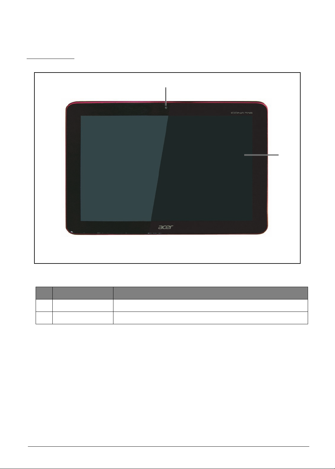
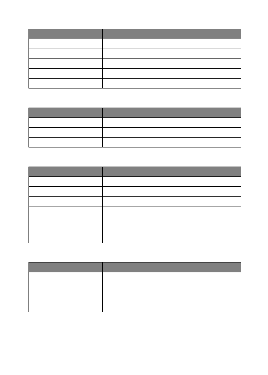
Front View
Figure 1:1. Front View
# Item Description
1 Camera A 2-megapixel camera for video chatting and self-portrait images.
2 Touch Screen 10.1-inch, 1280 x 800 capacitive touch screen.
Hardware Specifications and Configurations 1-5
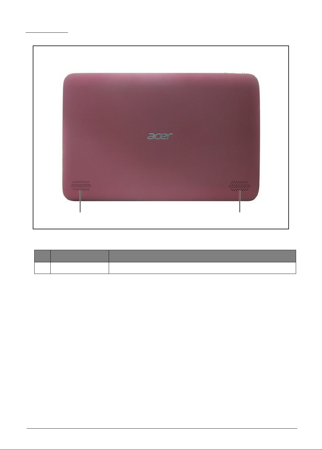
Rear View
1 1
Figure 1:2. Rear View
# Item Description
1 Speakers Emits stereo audio.
1-6 Hardware Specifications and Configurations
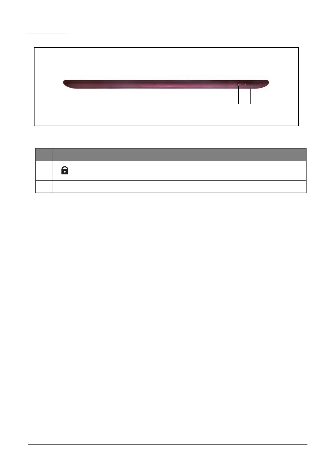
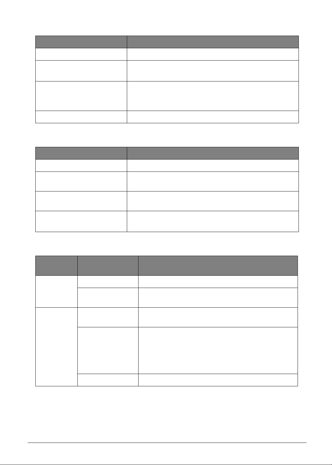
Top View
1 2
Figure 1:3. Top View
# Icon Item Description
1
2 Volume Con trol Increases or decreases the tablet volume.
Screen Rotation
Lock Switch
Use this switch to lock the screen rotation or allow the
screen to match the tablet’s orientation.
Hardware Specifications and Configurations 1-7
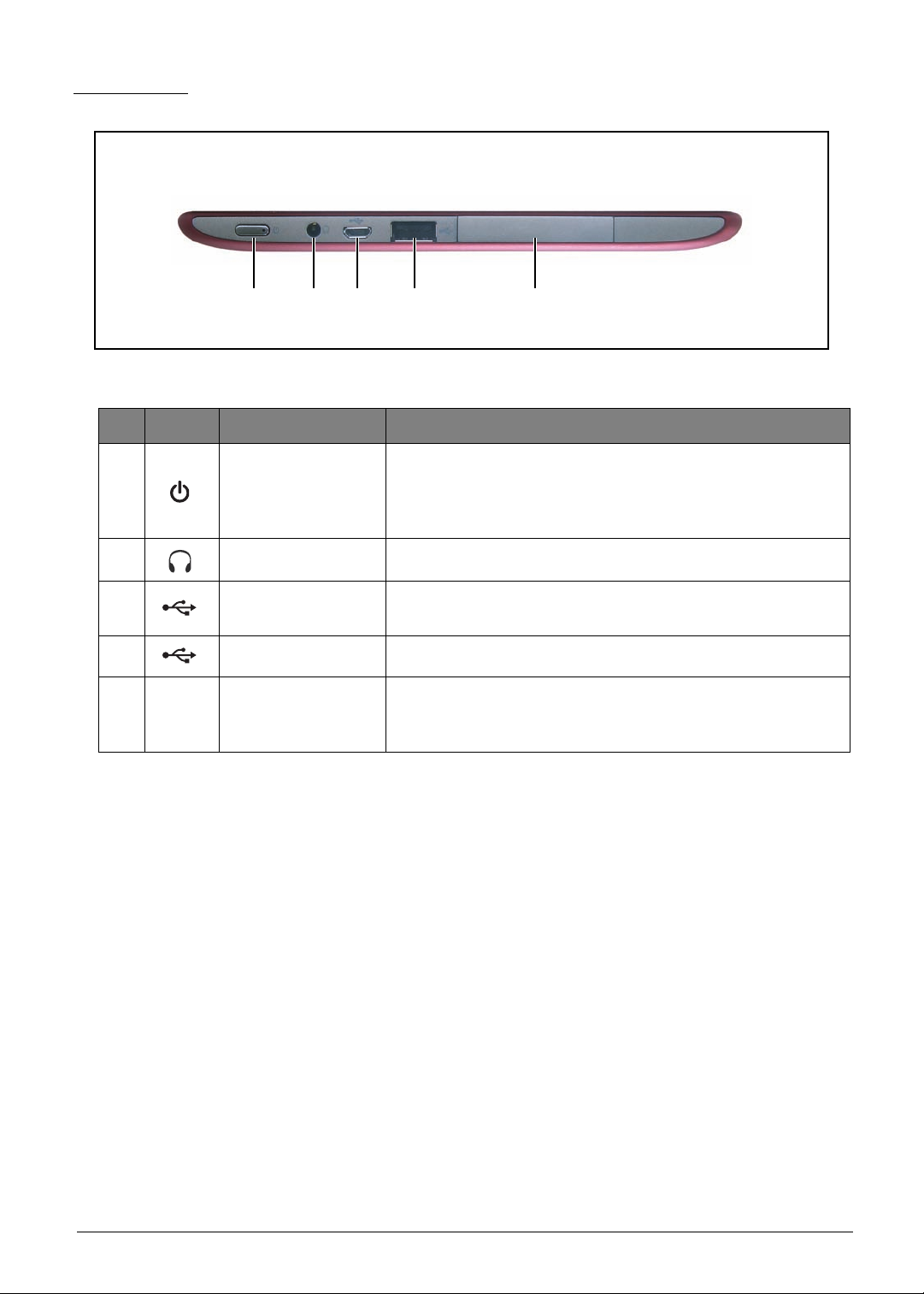
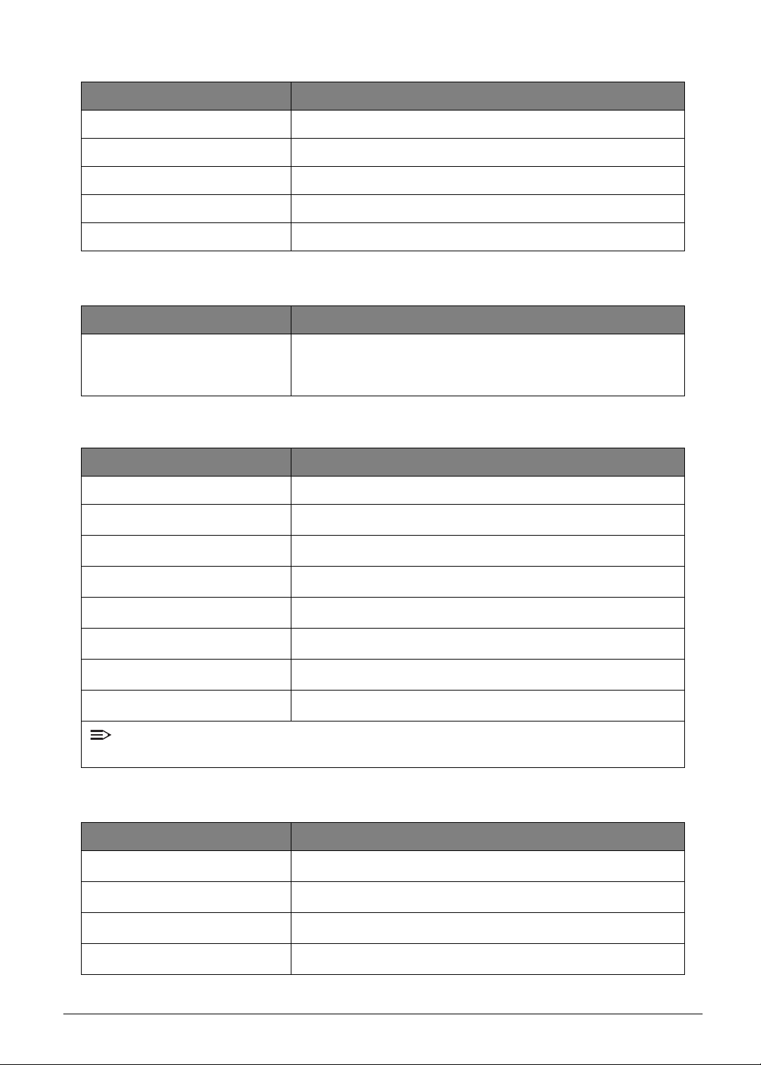
Left View
1 2 3 4 5
Figure 1:4. Left View
# Icon Item Description
• Long press to turn the tablet on.
1 Power Button
2 Headset Jack Connects to stereo headphones.
• Press briefly to turn the screen on/off or enter sleep
mode.
• Press and hold to turn the tablet off.
3
4 USB Port (host) Connects USB devices to the t ablet.
5
Micro USB Port
(slave)
Card Slot and
Reset Hole Cover
Connects to a computer with a USB cable.
• Insert a microSD card into the slot under this cover.
• Insert a pointed object, such as a paper clip, into the
reset hole to reset the tablet to its factory defaults.
1-8 Hardware Specifications and Configurations
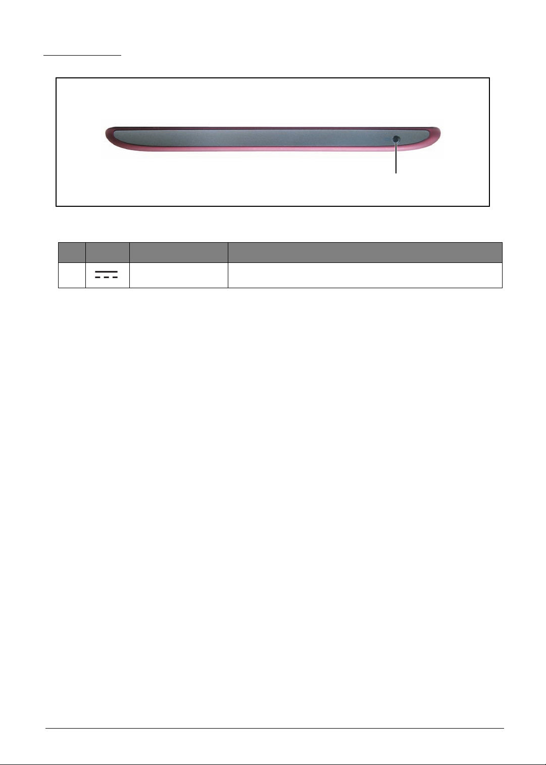
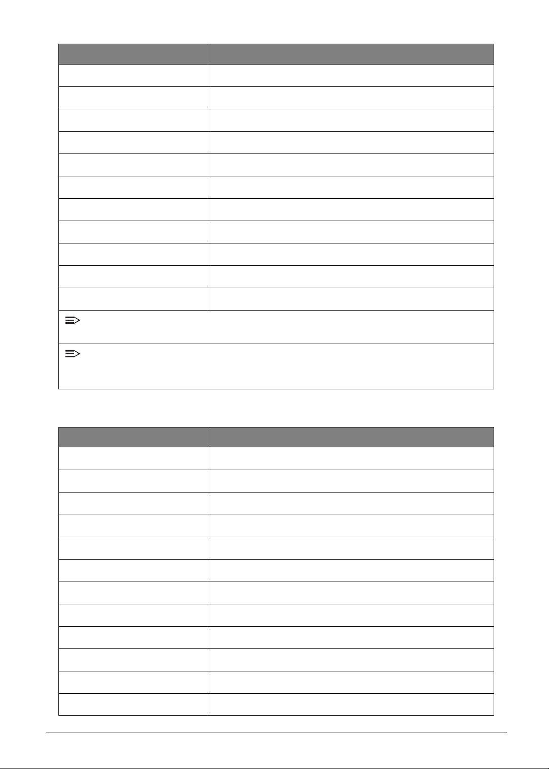
Right View
1
Figure 1:5. Right View
# Icon Item Description
1 AC Adapter Jack Connects to the power adapter.
Hardware Specifications and Configurations 1-9
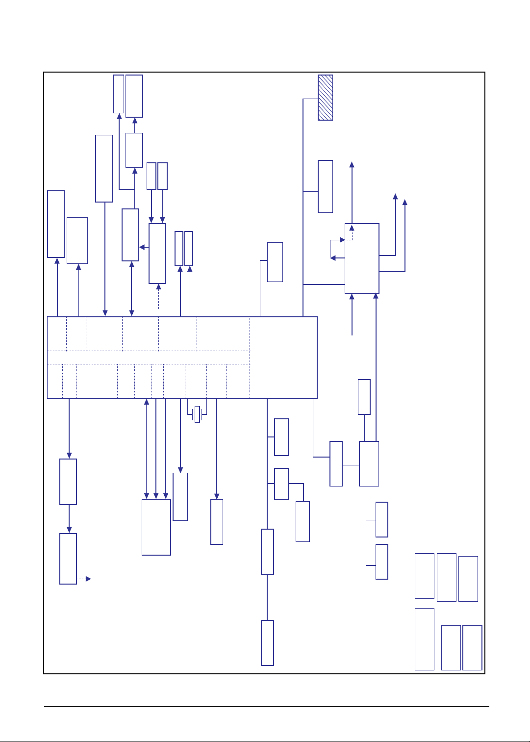
System Block Diagram
10.1’’LVDS panel
AP_SMB(3.3V)
T20 GEN2 12C
RGB(1.8V)
VGA
LCD
HDMI
ULPI
SDIOI
DAP4
UART
OSC,PLL,
SDIO3
core & fuse
NAND Ctrl
DDR
VI&DSI/CSI
AUDIO
USB +
mini-B
connector
HSIC
GPIO
12C
EC_RESMUE
EDID
WIFI
BT_MIC
BT
LVDS bridge
eMMC NAND 4.3 / 4.41
8 bits HSMMC
Nvidia Tegra T20
Client USB
USB1
Host USB
USB3
2M CAMERA
Module
Temperature
Sensor-NCT-1008
PMU TI TPS658621C
CAM_12C (1.8V)
PWR_12C (1.8V)
+5V_ALW Input
LDO 0~9 for CPU
+1V_SM0 for CPU
+1.2V_SM1 for CPU
2M CAMERA Module
SPKR AMP
ALC105
CSI B (1.2V)
Audio Codec
Wolfson WM8903
DAP1 (1.8V)
FM2018
Echo & Noise Cancel
INT Speaker
HeadPhone
EXT MIC
INT MIC
LPDDR2 X 1
512MB / 1GB
DDR2 32bits
(1.2V , 1.8V)
SDIOI(1.8V)
AW-NH611
WIFI/BT
module
BCM4751
GPS Module
DAP4(1.8V)
UART3(1.8V)
UART2(1.8V)
SDIO Card Slot
SDIO3(3.3V)
12MHz
12C Level shifter
12C Level shifter
FM2018
SPI ROM
2S1P BATT
TI TPS51220
5V/3.3V BUCK
CHARGER
DC IN
BATT IN
1.8V
BUCK
1.2V
BUCK
EC KB930
GYRO
MPU-3050
Accelerometer
KXTF9-4100
Audio Codec
WM-8903
GEN1_12C(3.3V) GEN1_12C(1.8V)
IME_12C(1.8V)
GEN2_12C(1.8V)
AP_SMB(3.3V)
Touch Screen
CANDO + Atmel
EC_SMB
SPI
ON/OFF #
EC_SMB
EcompossEcomposs
AK6975CAK6975C
Ecomposs
AK6975C
+3.7V_SM2
Figure 1:6. System Block Diagram
1-10 Hardware Specifications and Configurations
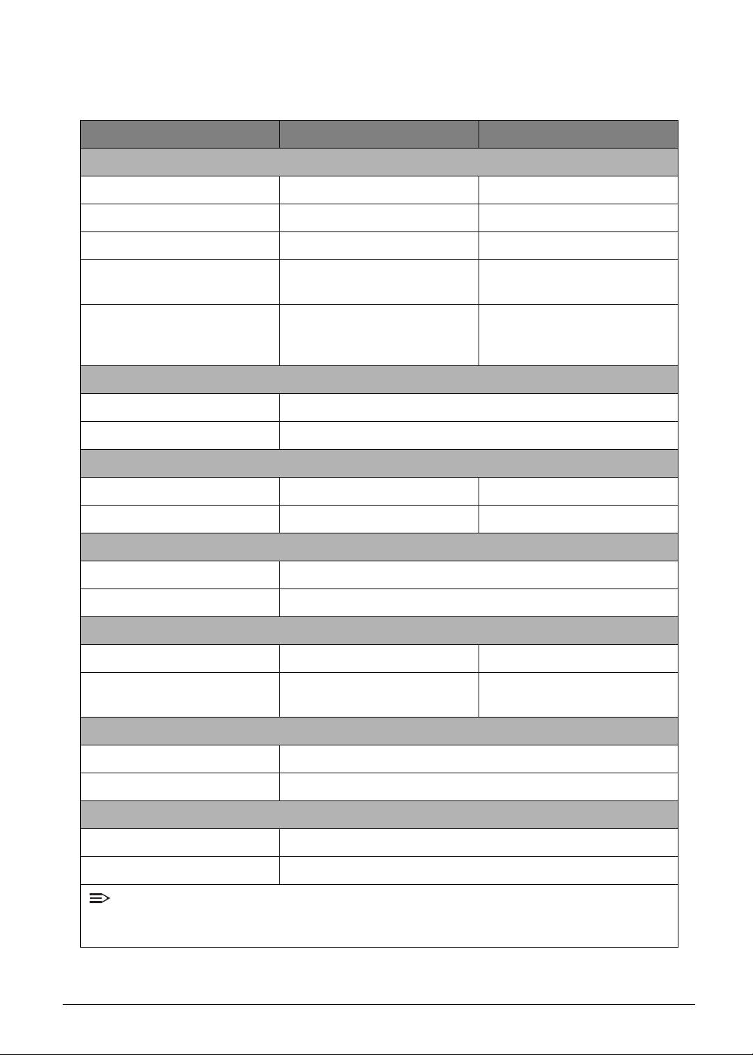
Specifications Table
Computer specifications
Item Metric Imperial
Dimensions
Length 260 mm 10.23 in
Width 175 mm 6.89 in
Height (front to rear) 12.4 mm 0.489 in
Weight (equipped with optical
drive, flash drive, and battery)
Weight (equipped with optical
drive, flash drive, and without
battery)
Input power
Operating voltage AC Input: 100V ~ 240V DC Output: 18W, 12V/1.5A
Operating current DC Output: 1.5A
Temperature
Operating -25º ~ 60ºC -13º ~ 140ºF
Non-operating -30º ~ 70ºC -22º ~ 158ºF
Relative humidity
Operating 5% ~ 90%
Non-operating 0% ~ 90%
Maximum altitude (unpressurized)
Operating 0 cm ~ 63 cm 0 ~ 2.07 ft.
Under 650g for Wi-Fi SKU Under 1.432 lbs
N/A N/A
Non-operating
Shock
Operating Amplitude: 105 g
Non-operating Amplitude: 220 g
Random vibration
Operating 1.644 g
Non-operating 1.644 g
NOTE:
Applicable product safety standards specify thermal limits for plastic surfaces. The computer
operates well within this range of temperatures.
Hardware Specifications and Configurations 1-11
0 cm ~ 63 cm free drop on
steal
0 ~ 2.07 ft. free drop on steal

System Board Major Chips
Item Specification
CPU
Graphics Processor
Ultra Low Power GeForce
Ultra Low Power GeForce
with programmable floating point pixel shaders and vertex
®
GPU
®
GPU supporting OpenGL® ES 2.0,
shaders
LVDS transmitter SN75LVDS83DGGRG4
PMU TI TPS658621AZGUR
LDDR2 MT46H64M32L2JG-5IT:A
ULPI Phy for USB N/A
Bluetooth AW-NH611
Wireless AW-NH611
GPS BCM4751IFBG
GPS Low-Noise Amplifier MAX2659ELT+
TOUCH controller mXT768E
eMMC 8G/16G (Base on Acer’s AVL)
CAMERA Aptina SOC 2031, 2M pixel
Tegra 250 Dual Cortex A9,1GHz
Thermal Sensor NCT1008CMT3R2G
Audio codec WM8903LGEFK-RV
Audio Amplifier ALC105-GR
Echo Cancellation FM2018WE-380
Battery Charger ISL6251AHAZ-T
Embedded Controller IC KB930QF-A1
Compass N/A
Gyro MPU-3050
G-Sensor KXTF9-4100
ALS/Proximity N/A
1-12 Hardware Specifications and Configurations
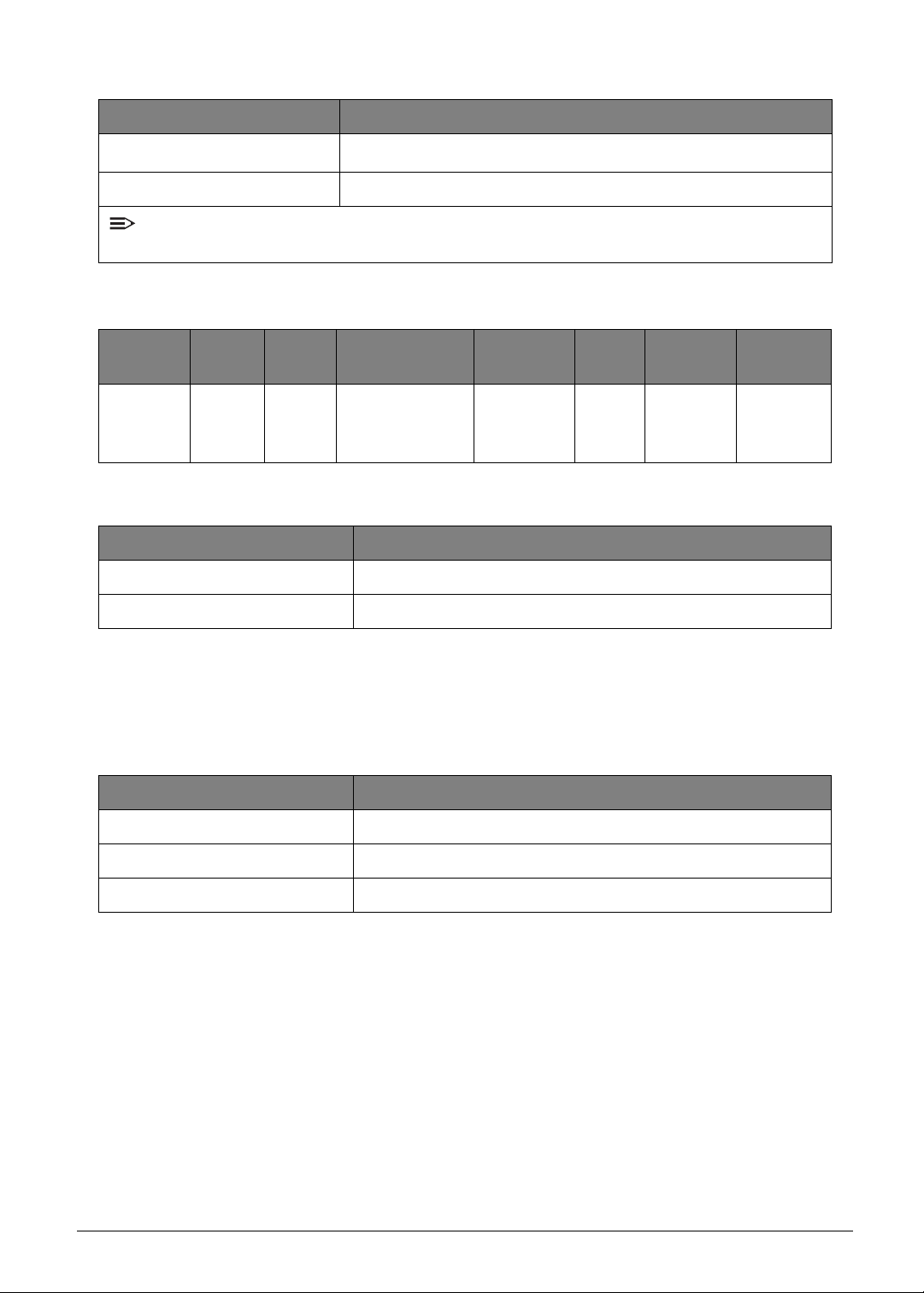
Processor
Item Specification
CPU
Dual-core ARM
®
Cortex-A9 MPCore™ Processor Up to 1 GHz
CPU package 664-ball FCBGA, 23 x 23 mm, 0.8 mm pitch
NOTE:
No CPU Fan in this product.
Processor Specifications
Item
Tegra 2
Series
CPU
Speed
1 GHz
Cores
Dual
Core
Bus Speed
(FSB/DMI/QBI)
N/A
Mfg Tech
40nm
LPG
TSMC
Cach
e Size
N/A
System Memory
Item Specification
Memory controller Embed in CPU
Memory size Up to 1 GB LPDDR2
Package
23 x 23
mm
FCBGA
Core
Voltage
1.0-1.2V
No Graphics Controller
N
oBIOSSetupMenuforthisproduct
LAN Interface
Item Specification
LAN Chipset On board LAN not supported
LAN connector type N/A
LAN connector location N/A
No Keyboard for this product
Hardware Specifications and Configurations 1-13
Hard Disk Drive Interface
Item Specification
Vendor &
Model Name
Capacity
(GB)
Kingston
KE44B-26BN/
16GB
16G 8G
Kingston
KE44B-26BN/
8GB
SanDisk
SDIN5C1-16G
DC Power Requirements
Voltage
tolerance
VCC: 2.85V
VCCQ: 1.8V
Audio Codec Interface
Item Specification
Audio Controller WM8903LGEFK-GV
Audio onboard or optional On board
Mono or Stereo Stereo
Resolution 24-bit data resolution
Compatibility I2S Interface;
Sampling rate Sample rate up to 44.1KHz
SanDisk
SDIN5C2-8G
16G 8G
Internal microphone Yes
Internal speaker/quantity Yes/(1W stereo speakers x1)
Phone Jack HP_Out + MIC
• 4.5mW power consumption for DAC to headphone
playback
• DAC SNR 96dB typical, THD -86dB typical
• ADC SNR 92dB typical, THD -80dB typical
• Control sequencer for pop minimized start-up and shutdown
• Single register write for default start-up sequence
• Integrated FLL provides all necessary clocks
• Self-clocking modes allow processor to sleep
Feature
• All standard sample rates from 8kHz to 96kHz
• Stereo digital microphone input
• 3 single ended inputs per stereo channel
• 1 fully differential mic / line input per stereo channel
• Digital Dynamic Range Controller (compressor / limiter)
• Digital side tone mixing
• Ground-referenced headphone driver
• Ground-referenced line outputs
• Stereo differential line driver for direct interface to
WM9001 speaker driver
• 40-pin QFN package (5x5mm)
1-14 Hardware Specifications and Configurations
Audio Amplifier IC
Item Specification
Amplifier IC ALC105-GR
• Single-Ended stereo analog input
• BTL (Bridge-Tied Load) output provides up to 3W per
channel driving capability into 4Ω speaker load (5V power
is supplied)
• No external output L-C filter required
Feature
• Supports pop noise suppression
• Configurable input to output boost gain ration
(+11dB/+14dB/+19dB/+25dB)
• Speaker amplifier power supplies from 3.3V to 5V
• 10µA Shut Down current
• High PSRR: 77dB
• DFN-12 package
LED 10.1”
Item Specification
AUO _ B101EVT03 V0
Vendor/model name
10.1”(10.07”) WXGA 16:10 Color TFT-LCD with LED
Backlight design
Screen Diagonal (mm) 255.85 mm
Active Area (mm) 216.96 mm x 135.6 mm
Display resolution (pixels) 1280 x 3(RGB) x 800
Pixel Pitch (mm) 0.1695 mm 0.1695 mm
Typical White Luminance
2
) also called Brightness
(cd/m
Contrast Ratio
Response Time (Optical Rise
Time/Fall Time) misc.
Typical Power Consumption
(watt)
Weight (without inverter/touch
screen)
Typ: 300 cd/m
Min.: 255 cd/m
Typ: 1300
Min.: 1000
Typ: 35 mS
Min.: 25 mS
Max:3.4 W
180g
2
2
Physical Size (mm) 229.95 mm x 149.6 mm x 5.2 max
Electrical Interface 1 channel LVDS
Hardware Specifications and Configurations 1-15
Item Specification
Viewing Angle (degree)
Horizontal (Right) CR = 10
(Left)
Vertical (Upper) CR = 10
Min.: 80 (Right) / 80 (Left) / 80 (Upper) / 80 (Lower)
Typ: 85 (Right) / 85 (Left) / 85 (Upper) / 85 (Lower)
(Lower)
No LCD Inverter for this product
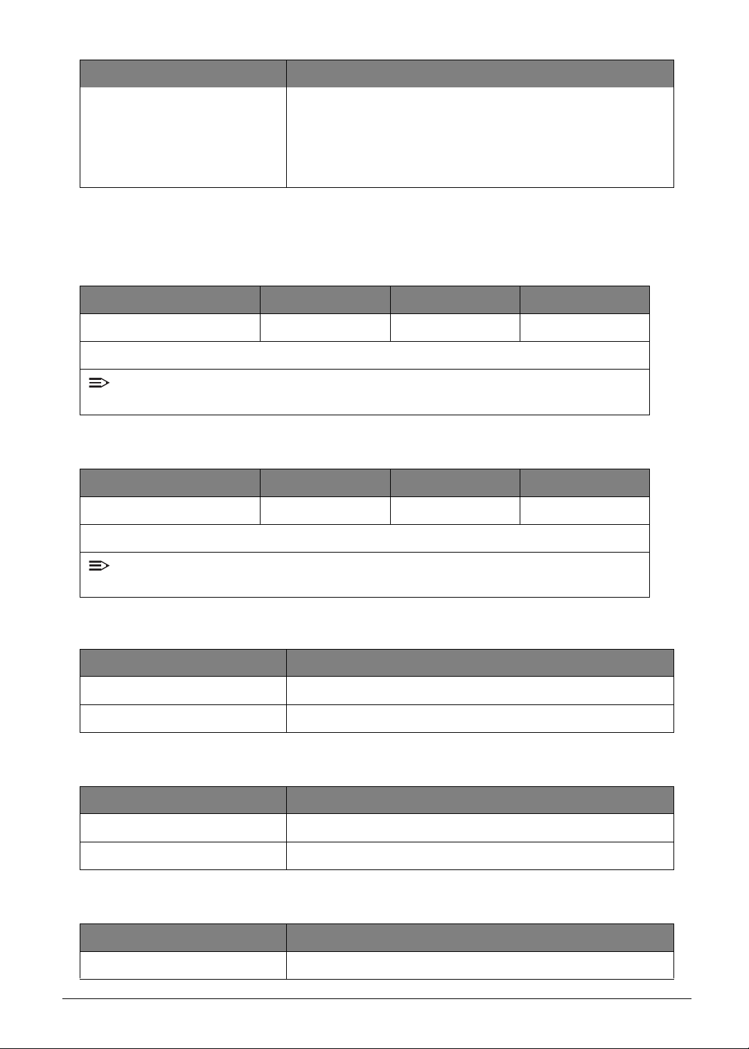
Display Supported Resolution (GPU Supported Resolution)
Resolution 16 bits 32 bits NVIDIA
1280 X 800 16:10 X X V
Legend: V = Supported; X = Not supported
NOTE:
Resolution
fixed at 1280 x 800. Not adjustable by end user.
Display Supported Resolution (LCD Panel Supported Resolution)
Resolution 16 bits 32 bits NVIDIA
1280 X 800 16:10 X X V
Legend: V = Supported; X = Not supported
NOTE:
Resolution
fixed at 1280 x 800. Not adjustable by end user.
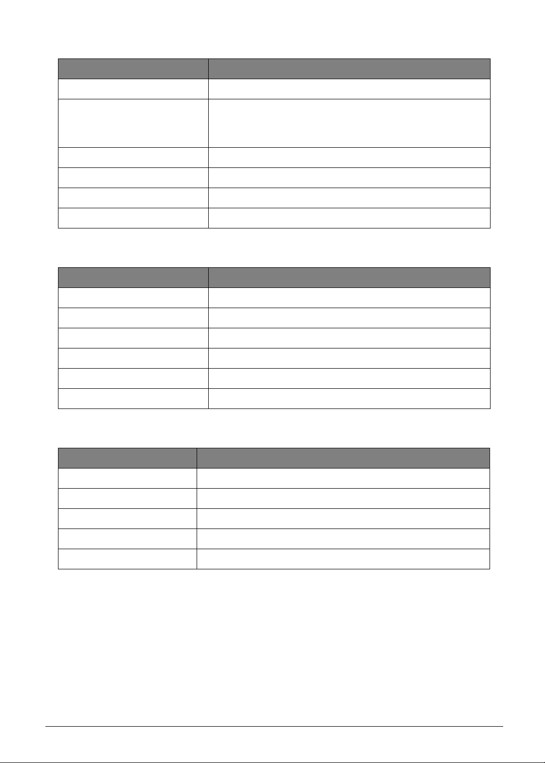
Camera
Item Specification
Vend or and model Chicony CJFB233
Type 2.0M
Mini Card
Item Specification
Number supported 0
Features Not supported
3G Card
Item Specification
Features Not supported
1-16 Hardware Specifications and Configurations
Wireless Module 802.11b/g/n
Item Specification
Chipset AW-NH611 SIP (include Broadcom BCM4329)
802.11b: 1, 2, 5.5, 11Mbps
Data throughput
802.11g: 6, 9, 12, 18, 24, 36, 48, 54Mbps
802.11n:MCS 0~7
Protocol IEEE 802.11b/g/n, Wi-Fi compliant
Interface SDIO/SPI
Connector type I-PEX
Supported protocol CCXv2/CCXv3/CCXv4/CCXv5, WFAEC
Bluetooth Module
Item Specification
Chipset AW-NH611 SIP (include Broadcom BCM4329)
Data throughput Bluetooth 2.1+EDR data rates of 1,2, and 3Mbps
Protocol Bluetooth 2.1+Enhanced Data Rate (EDR) / BT3.0+HS
Interface UART
Connector type I-PEX
Supported protocol N/A
Battery
Item Specification
Vendor & model name SANYO BAT1012
Battery Type Li-pol
Pack capacity 3280mAh/24Wh
Number of battery cell 2
Package configuration 2S1P
Hardware Specifications and Configurations 1-17
Video Inter face
Item Specification
Chipset N/A (Graphic function is embedded in CPU)
Package N/A
Interface N/A
Compatibility N/A
Sampling rate N/A
VRAM
Item Specification
Chipset N/A
Memory size N/A
Interface N/A
USB Port
Item Specification
USB compliance level USB2.0
Modes Host & Device
Speed Low, Full and High
Number of USB port(s) 2 ports (1 port for Host, 1 port for Device)
Location two at the right side
Output Current
0A (micro USB port, Device mode)
1.5A (USB port, Host mode)
HDMI Port
Item Specification
Compliance level N/A (Not supported)
Data throughput N/A
Number of HDMI port(s) N/A
Location N/A
1-18 Hardware Specifications and Configurations
AC Adapter
Item Specification
Total output power 18W
Maximum input AC current
0.5A(RMS)Max. @120Vac
0.25A(RMS)Max. @240Vac
40A Max. for 120VAC at Max load
Inrush current
60A Max. for 240VAC at Max load
(At cold start)
Efficiency Meet EPA 2.0
System Power Management
Item Specification
Mech. OFF Devices in the system are turned off completely.
Power OFF
Working
Deep Sleep
OS initiated shutdown. All devices in the system are turned
off completely.
The most of devices are turned on. Individual devices such
as the CPU may be power managed in this state.
CPU core power off
Others devices are standby
Power Specification
Legacy
Mode
Mech. Off (G3) All devices in the system are turned off complete ly
Off
Soft Off (G2/S5)
Working (G0/S0)
On
S3 Sleeping State
S4 Sleeping State N/A
ACPI Mode Power Management
OS initiated shutdown. All devices in the system are
turned off completely.
Individual devices such as the CPU and eMMC may be
power managed in this state.
CPU suspend
Audio Power Down
eMMC Power Down
LCD power off
MIC power off
Hardware Specifications and Configurations 1-19
MicroSD Card Reader
Item Specification
Chipset SD function is supported by CPU.
Package N/A
Interface SDIO
Maximum supported size Follow up SD card spec
Features Storage cards with adapter: microSD™
System LED Indicator
Item Specification
• White color solid on: System on
System state
• White color and amber color off: System off
• Amber color: Battery in charging
System DMA Specification (N/A)
Hardware DMA System Function
DMA0
DMA1
DMA2
DMA3
DMA4
DMA5
DMA6
DMA7
NOTE:
ExpressCard controller can use DMA 1, 2, or 5.
System Interrupt Specification (N/A)
Hardware IRQ System Function
IRQ0
IRQ1
IRQ2
IRQ3
1-20 Hardware Specifications and Configurations
Hardware IRQ System Function
IRQ5*
IRQ6
IRQ7*
IRQ8
IRQ9*
IRQ10*
IRQ11
IRQ12
IRQ13
IRQ14
IRQ15
NOTE:
Default configuration; audio possible configurations are IRQ5, IRQ7, IRQ9, IRQ10, or none.
NOTE:
ExpressCards may assert IRQ3, IRQ4, IRQ5, IRQ7, IRQ9, IRQ10, IRQ11, or IRQ15. Either
the infrared or the serial port may assert IRQ3 or IRQ4.
System IO Address Map (N/A)
I/O Address (hex) System Function (Shipping Configuration)
000 - 00F
010 - 01F
020 - 021
022 - 024
025 - 03F
02E - 02F
040 - 05F
044 - 05F
060
061
062 - 063
064
Hardware Specifications and Configurations 1-21
I/O Address (hex) System Function (Shipping Configuration)
065 - 06F
070 - 071
072 - 07F
080 - 08F
090 - 091
092
093 - 09F
0A0 - 0A1
I/O Address (hex)
0A2 - 0BF
0C0 - 0DF
0E0 - 0EF
0F0 - 0F1
0F2 - 0FF
100 - 16F
170 - 177
178 - 1EF
1F0 - 1F7
1F8 - 200
201
202 - 21F
System IO Address Specification (N/A)
I/O Address (hex) System Function (Shipping Configuration)
220 - 22F
230 - 26D
26E - 26
278 - 27F
280 - 2AB
1-22 Hardware Specifications and Configurations

I/O Address (hex) System Function (Shipping Configuration)
2A0 - 2A7
2A8 - 2E7
2E8 - 2EF
2F0 - 2F7
2F8 - 2FF
300 - 31F
320 - 36F
370 - 377
378 - 37F
380 - 387
388 - 38B
38C - 3AF
3B0 - 3BB
3BC - 3BF
3C0 - 3DF
3E0 - 3E1
3E2 - 3E3
3E8 - 3EF
3F0 - 3F7
3F8 - 3FF
CF8 - CFB
(PCIDIVO-1)
(PCIDIVO-1)
Hardware Specifications and Configurations 1-23

CHAPTER 2
Diagnostic Utilities
Diagnostic Utilities . . . . . . . . . . . . . . . . . . . . . . . . . . . . . . . . . . . . . . 2-2
Introduction . . . . . . . . . . . . . . . . . . . . . . . . . . . . . . . . . . . . . . . . . . . . . . . . . . . . 2-2
Diagnostic Tool SOP. . . . . . . . . . . . . . . . . . . . . . . . . . . . . . . . . . . . . . . . . . . . . 2-2
Preparation . . . . . . . . . . . . . . . . . . . . . . . . . . . . . . . . . . . . . . . . . . . . . . . . . 2-2
Tool Installation . . . . . . . . . . . . . . . . . . . . . . . . . . . . . . . . . . . . . . . . . . . . . . 2-2
Main Menu. . . . . . . . . . . . . . . . . . . . . . . . . . . . . . . . . . . . . . . . . . . . . . . . . . 2-4
Uninstallation Procedures . . . . . . . . . . . . . . . . . . . . . . . . . . . . . . . . . . . . . . 2-9
 Loading...