


TravelMate 4740/4740G/4740Z/4740ZG Series
Service Guide
Service guide files and updates are available
on the ACER/CSD web; for more information,
please refer to http://csd.acer.com.tw
PRINTED IN TAIWAN

Revision History
Please refer to the table below for the updates made on TravelMate 4740/4740G/4740Z/4740ZG Series
service guide.
Date Chapter Updates
II

Copyright
Copyright © 2010 by Acer Incorporated. All rights reserved. No part of this publication may be reproduced,
transmitted, transcribed, stored in a retrieval system, or translated into any language or computer language, in
any form or by any means, electronic, mechanical, magnetic, optical, chemical, manual or otherwise, without
the prior written permission of Acer Incorporated.
Disclaimer
The information in this guide is subject to change without notice.
Acer Incorporated makes no representations or warranties, either expressed or implied, with respect to the
contents hereof and specifically disclaims any warranties of merchantability or fitness for any particular
purpose. Any Acer Incorporated software described in this manual is sold or licensed "as is". Should the
programs prove defective following their purchase, the buyer (and not Acer Incorporated, its distributor, or its
dealer) assumes the entire cost of all necessary servicing, repair, and any incidental or consequential
damages resulting from any defect in the software.
Acer is a registered trademark of Acer Corporation.
Intel is a registered trademark of Intel Corporation.
Pentium and Pentium II/III are trademarks of Intel Corporation.
Other brand and product names are trademarks and/or registered trademarks of their respective holders.
III

Conventions
The following conventions are used in this manual:
SCREEN MESSAGES Denotes actual messages that appear
on screen.
NOTE Gives bits and pieces of additional
information related to the current
topic.
WARNING Alerts you to any damage that might
result from doing or not doing specific
actions.
CAUTION Gives precautionary measures to
avoid possible hardware or software
problems.
IMPORTANT Reminds you to do specific actions
relevant to the accomplishment of
procedures.
IV

Preface
Before using this information and the product it supports, please read the following general information.
1. This Service Guide provides you with all technical information relating to the BASIC CONFIGURATION
decided for Acer's "global" product offering. To better fit local market requirements and enhance product
competitiveness, your regional office MAY have decided to extend the functionality of a machine (e.g.
add-on card, modem, or extra memory capability). These LOCALIZED FEATURES will NOT be covered
in this generic service guide. In such cases, please contact your regional offices or the responsible
personnel/channel to provide you with further technical details.
2. Please note WHEN ORDERING FRU PARTS, that you should check the most up-to-date information
available on your regional web or channel. If, for whatever reason, a part number change is made, it will
not be noted in the printed Service Guide. For ACER-AUTHORIZED SERVICE PROVIDERS, your Acer
office may have a DIFFERENT part number code to those given in the FRU list of this printed Service
Guide. You MUST use the list provided by your regional Acer office to order FRU parts for repair and
service of customer machines.
V

VI

Table of Contents
Chapter 1 System Introduction 1
Features . . . . . . . . . . . . . . . . . . . . . . . . . . . . . . . . . . . . . . . . . . . . . . . . . . . . . . . . . . . .1
Your Acer Notebook Tour . . . . . . . . . . . . . . . . . . . . . . . . . . . . . . . . . . . . . . . . . . . . . .11
Hotkeys . . . . . . . . . . . . . . . . . . . . . . . . . . . . . . . . . . . . . . . . . . . . . . . . . . . . . . . .12
Closed Front View . . . . . . . . . . . . . . . . . . . . . . . . . . . . . . . . . . . . . . . . . . . . . . .13
Left View . . . . . . . . . . . . . . . . . . . . . . . . . . . . . . . . . . . . . . . . . . . . . . . . . . . . .13
Right View . . . . . . . . . . . . . . . . . . . . . . . . . . . . . . . . . . . . . . . . . . . . . . . . . . . .13
Base View . . . . . . . . . . . . . . . . . . . . . . . . . . . . . . . . . . . . . . . . . . . . . . . . . . . . .14
Hardware Specifications and Configurations . . . . . . . . . . . . . . . . . . . . . . . . . . . . . . .15
Chapter 2 System Utilities 23
Phoenix SecureCore Setup Utility . . . . . . . . . . . . . . . . . . . . . . . . . . . . . . . . . . . . . . .23
Accessing the Setup Utility . . . . . . . . . . . . . . . . . . . . . . . . . . . . . . . . . . . . . . . . . . . . .24
Navigating through the Setup Utility . . . . . . . . . . . . . . . . . . . . . . . . . . . . . . . . . .25
BIOS Setup Utility Menus . . . . . . . . . . . . . . . . . . . . . . . . . . . . . . . . . . . . . . . . . .25
Information . . . . . . . . . . . . . . . . . . . . . . . . . . . . . . . . . . . . . . . . . . . . . . . . . . . . .26
Main . . . . . . . . . . . . . . . . . . . . . . . . . . . . . . . . . . . . . . . . . . . . . . . . . . . . . . . . . .27
Security . . . . . . . . . . . . . . . . . . . . . . . . . . . . . . . . . . . . . . . . . . . . . . . . . . . . . . . .28
Boot . . . . . . . . . . . . . . . . . . . . . . . . . . . . . . . . . . . . . . . . . . . . . . . . . . . . . . . . . . .31
Exit . . . . . . . . . . . . . . . . . . . . . . . . . . . . . . . . . . . . . . . . . . . . . . . . . . . . . . . . . . .32
Updating the BIOS . . . . . . . . . . . . . . . . . . . . . . . . . . . . . . . . . . . . . . . . . . . . . . . . . . .33
Chapter 3 Machine Disassembly and Replacement 35
Disassembly Requirements . . . . . . . . . . . . . . . . . . . . . . . . . . . . . . . . . . . . . . . . . . . .35
General Information . . . . . . . . . . . . . . . . . . . . . . . . . . . . . . . . . . . . . . . . . . . . . . . . . .36
Pre-disassembly Instructions . . . . . . . . . . . . . . . . . . . . . . . . . . . . . . . . . . . . . . .36
Disassembly Process . . . . . . . . . . . . . . . . . . . . . . . . . . . . . . . . . . . . . . . . . . . . .36
External Module Disassembly Process . . . . . . . . . . . . . . . . . . . . . . . . . . . . . . . . . . .37
External Modules Disassembly Flowchart . . . . . . . . . . . . . . . . . . . . . . . . . . . . .37
Removing the Battery Pack . . . . . . . . . . . . . . . . . . . . . . . . . . . . . . . . . . . . . . . .38
Removing the Card Reader Dummy Card . . . . . . . . . . . . . . . . . . . . . . . . . . . . .38
Removing the Back Cover . . . . . . . . . . . . . . . . . . . . . . . . . . . . . . . . . . . . . . . . .39
Removing the Hard Disk Drive Module . . . . . . . . . . . . . . . . . . . . . . . . . . . . . . . .39
Removing the DIMM Modules . . . . . . . . . . . . . . . . . . . . . . . . . . . . . . . . . . . . . . .41
Removing the WLAN Module . . . . . . . . . . . . . . . . . . . . . . . . . . . . . . . . . . . . . . .41
Main Unit Disassembly Process . . . . . . . . . . . . . . . . . . . . . . . . . . . . . . . . . . . . . . . . .43
Main Unit Disassembly Flowchart . . . . . . . . . . . . . . . . . . . . . . . . . . . . . . . . . . . .43
Removing the Optical Drive . . . . . . . . . . . . . . . . . . . . . . . . . . . . . . . . . . . . . . . .44
Removing the Keyboard . . . . . . . . . . . . . . . . . . . . . . . . . . . . . . . . . . . . . . . . . . .45
Removing the Upper Case . . . . . . . . . . . . . . . . . . . . . . . . . . . . . . . . . . . . . . . . .45
Removing the Power Button Board . . . . . . . . . . . . . . . . . . . . . . . . . . . . . . . . . . .49
Removing the Speakers . . . . . . . . . . . . . . . . . . . . . . . . . . . . . . . . . . . . . . . . . . .50
Removing the Touchpad Board . . . . . . . . . . . . . . . . . . . . . . . . . . . . . . . . . . . . .51
Removing the LCD Module . . . . . . . . . . . . . . . . . . . . . . . . . . . . . . . . . . . . . . . . .51
Removing the USB Board . . . . . . . . . . . . . . . . . . . . . . . . . . . . . . . . . . . . . . . . . .53
Removing the Bluetooth Module . . . . . . . . . . . . . . . . . . . . . . . . . . . . . . . . . . . . .54
Removing the Mainboard . . . . . . . . . . . . . . . . . . . . . . . . . . . . . . . . . . . . . . . . . .55
VII

Table of Contents
Removing the Heatsink Fan Module . . . . . . . . . . . . . . . . . . . . . . . . . . . . . . . . . .56
Removing the Processor . . . . . . . . . . . . . . . . . . . . . . . . . . . . . . . . . . . . . . . . . . .57
LCD Module Disassembly Process . . . . . . . . . . . . . . . . . . . . . . . . . . . . . . . . . . . . . .59
LCD Module Disassembly Flowchart . . . . . . . . . . . . . . . . . . . . . . . . . . . . . . . . .59
Removing the LCD Bezel . . . . . . . . . . . . . . . . . . . . . . . . . . . . . . . . . . . . . . . . . .60
Removing the LCD Panel . . . . . . . . . . . . . . . . . . . . . . . . . . . . . . . . . . . . . . . . . .61
Removing the LCD Hinges . . . . . . . . . . . . . . . . . . . . . . . . . . . . . . . . . . . . . . . . .62
Removing the Webcam Module . . . . . . . . . . . . . . . . . . . . . . . . . . . . . . . . . . . . .62
Removing the Microphone . . . . . . . . . . . . . . . . . . . . . . . . . . . . . . . . . . . . . . . . .63
Removing the WLAN Antennas . . . . . . . . . . . . . . . . . . . . . . . . . . . . . . . . . . . . .63
Chapter 4 Troubleshooting 65
System Check Procedures . . . . . . . . . . . . . . . . . . . . . . . . . . . . . . . . . . . . . . . . . . . . .66
External Diskette Drive Check . . . . . . . . . . . . . . . . . . . . . . . . . . . . . . . . . . . . . .66
External Optical Drive Check . . . . . . . . . . . . . . . . . . . . . . . . . . . . . . . . . . . . . . .66
Keyboard or Auxiliary Input Device Check . . . . . . . . . . . . . . . . . . . . . . . . . . . . .66
Memory Check . . . . . . . . . . . . . . . . . . . . . . . . . . . . . . . . . . . . . . . . . . . . . . . . . .67
Power System Check . . . . . . . . . . . . . . . . . . . . . . . . . . . . . . . . . . . . . . . . . . . . .67
Touchpad Check . . . . . . . . . . . . . . . . . . . . . . . . . . . . . . . . . . . . . . . . . . . . . . . . .68
Power-On Self-Test (POST) Error Message . . . . . . . . . . . . . . . . . . . . . . . . . . . . . . .68
Index of Error Messages . . . . . . . . . . . . . . . . . . . . . . . . . . . . . . . . . . . . . . . . . . . . . . .69
Error Codes . . . . . . . . . . . . . . . . . . . . . . . . . . . . . . . . . . . . . . . . . . . . . . . . . . . .69
Error Messages . . . . . . . . . . . . . . . . . . . . . . . . . . . . . . . . . . . . . . . . . . . . . . . . . .69
No Beep Error Messages . . . . . . . . . . . . . . . . . . . . . . . . . . . . . . . . . . . . . . . . . .71
Phoenix BIOS Beep Codes . . . . . . . . . . . . . . . . . . . . . . . . . . . . . . . . . . . . . . . . . . . .72
Symptom-to-FRU Error Messages . . . . . . . . . . . . . . . . . . . . . . . . . . . . . . . . . . . . . . .76
Intermittent Problems . . . . . . . . . . . . . . . . . . . . . . . . . . . . . . . . . . . . . . . . . . . . . . . . .79
Undetermined Problems . . . . . . . . . . . . . . . . . . . . . . . . . . . . . . . . . . . . . . . . . . . . . . .80
Block Diagram . . . . . . . . . . . . . . . . . . . . . . . . . . . . . . . . . . . . . . . . . . . . . . . . . . . . . .81
Chapter 5 System Architecture 81
Mainboard Layout . . . . . . . . . . . . . . . . . . . . . . . . . . . . . . . . . . . . . . . . . . . . . . . . . . . .82
Clearing a BIOS Password . . . . . . . . . . . . . . . . . . . . . . . . . . . . . . . . . . . . . . . . . . . . .85
Unlocking the HDD . . . . . . . . . . . . . . . . . . . . . . . . . . . . . . . . . . . . . . . . . . . . . . . . . . .86
BIOS Recovery . . . . . . . . . . . . . . . . . . . . . . . . . . . . . . . . . . . . . . . . . . . . . . . . . . . . . .87
Creating the BIOS Crisis Recovery Disk in Windows . . . . . . . . . . . . . . . . . . . . .87
Performing a BIOS Recovery . . . . . . . . . . . . . . . . . . . . . . . . . . . . . . . . . . . . . . .87
Running the Flash Utility . . . . . . . . . . . . . . . . . . . . . . . . . . . . . . . . . . . . . . . . . . .87
Chapter 6 FRU (Field Replaceable Unit) List 89
Exploded Diagram . . . . . . . . . . . . . . . . . . . . . . . . . . . . . . . . . . . . . . . . . . . . . . . . . . .90
FRU List . . . . . . . . . . . . . . . . . . . . . . . . . . . . . . . . . . . . . . . . . . . . . . . . . . . . . . . . . . .91
Appendix A Model Definition and Configuration 99
TravelMate 4740 . . . . . . . . . . . . . . . . . . . . . . . . . . . . . . . . . . . . . . . . . . . . . . . . . . . .100
Travelmate 4740G . . . . . . . . . . . . . . . . . . . . . . . . . . . . . . . . . . . . . . . . . . . . . . . . . .121
Travelmate 4740Z . . . . . . . . . . . . . . . . . . . . . . . . . . . . . . . . . . . . . . . . . . . . . . . . . . .144
Travelmate 4740ZG . . . . . . . . . . . . . . . . . . . . . . . . . . . . . . . . . . . . . . . . . . . . . . . . .145
VIII

Table of Contents
Appendix B Test Compatible Components 147
Hardware Device Tests . . . . . . . . . . . . . . . . . . . . . . . . . . . . . . . . . . . . . . . . . . . . . .148
Appendix C Online Support Information 151
Index 153
IX

Table of Contents
X
Chapter 1
System Introduction
Features
Below is a brief summary of the TravelMate 4740/4740G/4740Z/4740ZG Series computer’s many features.
TravelMate 4740/4740Z
Operating System
Travelmate 4740 Travelmate 4740Z
• Genuine Windows® 7 Professional 32-bit
• Genuine Windows® 7 Home Premium 64-bit
• Genuine Windows® 7 Home Basic 64-bit
Platform
Travelmate 4740 Travelmate 4740Z
• Intel® Core i5-430M/i5-520M/i5-540M processor (3 MB
L3 cache, 2.26/2.40/2.53 GHz with Turbo Boost up to
2.53/2.93/3.06 GHz, DDR3 1066 MHz, 35 W),
supporting Intel® 64 architecture, Intel® Smart Cache
• Intel® Core™ i3-330M/i3-350M processor (3 MB L3
cache, 2.13/2.26 GHz, DDR3 1066 MHz, 35 W),
supporting Intel® 64 architecture, Intel® Smart Cache
• Mobile Intel® HM55 Express Chipset
• Genuine Windows® 7 Home Premium 64-bit
• Genuine Windows® 7 Home Basic 64-bit
• Intel® Pentium® processor P6000 (3 MB L3 cache,
1.86 GHz, DDR3 1066 MHz, 35 W), supporting Intel®
64 architecture, Intel® Smart Cache
• Mobile Intel® HM55 Express Chipset
System Memory
Travelmate 4740 Travelmate 4740Z
• Dual-channel DDR3 SDRAM support
• Up to 4 GB of DDR3 system memory, upgradable
to 8 GB using two soDIMM modules5 (for 64-bit
OS)
• Up to 2 GB of DDR3 system memory, upgradable
to 4 GB using two soDIMM modules6 (for 32-bit
OS)
• Dual-channel DDR3 SDRAM support:
• Up to 4 GB of DDR3 system memory, upgradable
to 8 GB using two soDIMM modules5 (for 64-bit
OS)
• Up to 2 GB of DDR3 system memory, upgradable
to 4 GB using two soDIMM modules6 (for 32-bit
OS)
Display
Travelmate 4740 Travelmate 4740Z
• 14" HD 1366 x 768 pixel resolution, high-brightness
LED-backlit TFT LCD
• Glare / anti-glare option
• Mercury free, environment friendly
• 14" HD 1366 x 768 pixel resolution, high-brightness
LED-backlit TFT LCD
• Glare / anti-glare option
• Mercury free, environment friendly
Chapter 1 1
Graphics
Travelmate 4740 Travelmate 4740Z
• Intel® HD Graphics with 128 MB of dedicated system
memory, supporting Microsoft® DirectX® 10
• Dual independent display support
• 16.7 million colors
• External resolution / refresh rates:
• VGA port up to 2560 x 1600: 60 Hz
• HDMI™ port up to 1920 x 1080: 60 Hz
• MPEG-2/DVD decoding
• WMV9 (VC-1) and H.264 (AVC) decoding
• HDMI™ (High-Definition Multimedia Interface) with
HDCP (High-bandwidth Digital Content Protection)
support
Storage subsystem
Travelmate 4740 Travelmate 4740Z
• 2.5" hard disk drive
• DVD-Super Multi double-layer drive
• Multi-in-1 card reader
• 2.5" hard disk drive
• DVD-Super Multi double-layer drive
• Multi-in-1 card reader
Audio
Travelmate 4740 Travelmate 4740Z
• Two built-in stereo speakers
• High-definition audio support
• Built-in microphone
• MS-Sound compatible
• Two built-in stereo speakers
• High-definition audio support
• Built-in microphone
• MS-Sound compatible
Storage
Travelmate 4740 Travelmate 4740Z
• 160/250/320/500/640 GB or larger hard disk drive
• Multi-in-1 card reader, supporting Secure Digital™ (SD)
Card, MultiMediaCard (MMC), Memory Stick™ (MS),
Memory Stick PRO™ (MS PRO), xD-Picture Card™
(xD)
• 160/250/320/500/640 GB or larger hard disk drive
• Multi-in-1 card reader, supporting Secure Digital™ (SD)
Card, MultiMediaCard (MMC), Memory Stick™ (MS),
Memory Stick PRO™ (MS PRO), xD-Picture Card™
(xD)
Optical Media Drive
Travelmate 4740 Travelmate 4740Z
• 8X DVD-Super Multi double-layer drive:
• Read: 24X CD-ROM, 24X CD-R, 24X CD-RW, 8X
DVD-ROM, 8X DVD-R, 8X DVD+R, 6X DVD-ROM
DL, 6X DVD-R DL, 6X DVD+R DL, 6X DVD-RW,
6X DVD+RW, 5X DVD-RAM
• Write: 24X CD-R, 16X CD-RW, 8X DVD-R, 8X
DVD+R, 4X DVD-R DL, 4X DVD+R DL, 6X DVDRW, 8X DVD+RW, 5X DVD-RAM
• 8X DVD-Super Multi double-layer drive:
• Read: 24X CD-ROM, 24X CD-R, 24X CD-RW, 8X
DVD-ROM, 8X DVD-R, 8X DVD+R, 6X DVD-ROM
DL, 6X DVD-R DL, 6X DVD+R DL, 6X DVD-RW,
6X DVD+RW, 5X DVD-RAM
• Write: 24X CD-R, 16X CD-RW, 8X DVD-R, 8X
DVD+R, 4X DVD-R DL, 4X DVD+R DL, 6X DVDRW, 8X DVD+RW, 5X DVD-RAM
2 Chapter 1
Communication
Travelmate 4740 Travelmate 4740Z
• Acer Video Conference, featuring:
• Acer Crystal Eye webcam with 1280 x 1024
resolution
• Acer Video Conference Manager software,
featuring Video Quality Enhancement (VQE)
technology, supporting 640 x 480 resolution online
video calls
•WLAN:·
• Acer InviLink™ Nplify™ 802.11b/g/n Wi-Fi
CERTIFIED™
• Acer InviLink™ 802.11b/g Wi-Fi CERTIFIED™
• Supporting Acer SignalUp™ wireless technology
•WPAN:
• Bluetooth® 3.0+HS
• Bluetooth® 2.1+EDR
•LAN
• Gigabit Ethernet, Wake-on-LAN ready
•WWAN
• UMTS/HSPA at 850/900/1900/2100 MHz and
quad-band GSM/GPRS/EDGE (850/900/1800/
1900 MHz) upgradeable to 7.2 Mb/s HSDPA and
5.7 Mb/s HSUPA
Privacy control
Travelmate 4740 Travelmate 4740Z
• BIOS user, supervisor, HDD passwords
• Kensington lock slot
• BIOS user, supervisor, HDD passwords
• Kensington lock slot
Dimensions and weight
Travelmate 4740 Travelmate 4740Z
• 342 (W) x 245 (D) x 26.3/33.2 (H) mm (13.5 x 9.6 x
1.03/1.31 inches)
• 2.2 kg (4.85 lbs.) with 6-cell battery pack
• 342 (W) x 245 (D) x 26.3/33.2 (H) mm (13.5 x 9.6 x
1.03/1.31 inches)
• 2.2 kg (4.85 lbs.) with 6-cell battery pack
Power subsystem
Travelmate 4740 Travelmate 4740Z
• ACPI 3.0 CPU power management standard: supports
Standby and Hibernation power-saving modes
• 3-pin 65 W AC adapter:
• 108 (W) x 46 (D) x 29.5 (H) mm (4.25 x 1.81 x 1.16
inches)
• 225 g (0.49 lbs.) with 180 cm DC cable
• 48.8 W 4400 mAh 6-cell Li-ion standard battery pack
• Battery life: 4.0 hours
• ENERGY STAR®
Chapter 1 3
Special keys and controls
Travelmate 4740 Travelmate 4740Z
• 88-/89-/93-key keyboard with inverted "T" cursor layout
• 10 function keys, four cursor keys, two Windows®
keys, hotkey controls, embedded numeric keypad,
international language support, independent US dollar
and Euro symbol keys
• Multi-gesture touchpad, supporting two-finger scroll,
pinch, rotate, flip
• Media control keys (printed on keyboard): play/pause,
stop, previous, next
I/O interface
Travelmate 4740 Travelmate 4740Z
• Multi-in-1 card reader (SD™, MMC, MS, MS PRO, xD)
• Three USB 2.0 ports
• HDMI™ port with HDCP support
• External display (VGA) port
• Headphone/speaker/line-out jack
• Microphone-in jack
• Ethernet (RJ-45) port
• DC-in jack for AC adapter
• Multi-in-1 card reader (SD™, MMC, MS, MS PRO, xD)
• Three USB 2.0 ports
• HDMI™ port with HDCP support
• External display (VGA) port
• Headphone/speaker/line-out jack
• Microphone-in jack
• Ethernet (RJ-45) port
• DC-in jack for AC adapter
Software
Travelmate 4740 Travelmate 4740Z
• Acer Backup Manager
• Acer ePower Management
• Acer eRecovery Management
• Acer Optical Drive Power Management
• Microsoft® Office Personal 2007 (Service Pack 2)
(Japan only, subject to customer request)
• Microsoft® Office Ready (Service Pack 2)
• Google Toolbar™
• Adobe® Flash® Player 10
• Adobe® Reader® 9.1
• eSobi™
• Norton™ Online Backup
• McAfee® Internet Security Suite Trial
• Corel® WinDVD
• NTI Media Maker™
• Acer 3G Connection Manager
• Acer Crystal Eye
• Acer Video Conference Manager
• Microsoft® Silverlight™
• Skype™
• Windows Live™ Essentials - Wave 3.2 (Mail, Photo
Gallery, Live™ Messenger, Movie Maker, Writer)
• Acer Accessory Store1 (Belgium, France, Germany,
Italy, Netherlands, Spain, Sweden, UK only)
• Acer Assist
• Acer Identity Card
• Acer Registration
• Acer 3G Connection Manager
• Acer Crystal Eye
• Acer Launch Manager
• Acer Video Conference Manager
• Adobe® Flash® Player
• Adobe® Reader®
• Corel® WinDVD®
• eSobi™
• Google™ Toolbar
• McAfee® Internet Security Suite Trial
• Microsoft® Office Professional 2007 Trial (Service Pack
2)
• Microsoft® Office Personal 2007 (Service Pack 2)
(Japan only)
• Microsoft® Silverlight
• Norton™ Online Backup
• NTI Media Maker™
• Skype™
• Windows Live™ Essentials
4 Chapter 1
• Acer Updater
• eBay® shortcut 20091 (Canada, France, Germany,
Italy, Mexico, Spain, UK, US only)
• Netflix shortcut1 (US only)
Optional Items
Travelmate 4740 Travelmate 4740Z
• 1 GB / 2 GB / 4 GB DDR3 1066 MHz soDIMM module
• 6-cell Li-ion battery pack
• 3-pin 65 W AC adapter
• 1 GB / 2 GB / 4 GB DDR3 1066 MHz soDIMM module
• 6-cell Li-ion battery pack
• 3-pin 65 W AC adapter
Warranty
Travelmate 4740 Travelmate 4740Z
One-year International Travelers Warranty (ITW) One-year International Travelers Warranty (ITW)
Environment
Travelmate 4740 Travelmate 4740Z
• Temperature:
• Operating: 5 C to 35 C
• Non-operating: -20 C to 65 C
• Humidity (non-condensing):
• Operating: 20%~80%
• Non-operating: 20%~80%
• Temperature:
• Operating: 5 C to 35 C
• Non-operating: -20 C to 65 C
• Humidity (non-condensing):
• Operating: 20%~80%
• Non-operating: 20%~80%
Chapter 1 5
TravelMate 4740G/4740ZG
Operating System
Travelmate 4740G Travelmate 4740ZG
• Genuine Windows® 7 Professional 32-bit
• Genuine Windows® 7 Home Premium 64-bit
• Genuine Windows® 7 Home Basic 64-bit
Platform
Travelmate 4740G Travelmate 4740ZG
• Intel® Core i5-430M/i5-520M/i5-540M processor (3 MB
L3 cache, 2.26/2.40/2.53 GHz with Turbo Boost up to
2.53/2.93/3.06 GHz, DDR3 1066 MHz, 35 W),
supporting Intel® 64 architecture, Intel® Smart Cache
• Intel® Core™ i3-330M/i3-350M processor (3 MB L3
cache, 2.13/2.26 GHz, DDR3 1066 MHz, 35 W),
supporting Intel® 64 architecture, Intel® Smart Cache
• Mobile Intel® HM55 Express Chipset
System Memory
Travelmate 4740G Travelmate 4740ZG
• Dual-channel DDR3 SDRAM support
• Up to 4 GB of DDR3 system memory, upgradable
to 8 GB using two soDIMM modules5 (for 64-bit
OS)
• Up to 2 GB of DDR3 system memory, upgradable
to 4 GB using two soDIMM modules6 (for 32-bit
OS)
• Genuine Windows® 7 Home Premium 64-bit
• Genuine Windows® 7 Home Basic 64-bit
• Intel® Pentium® processor P6000 (3 MB L3 cache,
1.86 GHz, DDR3 1066 MHz, 35 W), supporting Intel®
64 architecture, Intel® Smart Cache
• Mobile Intel® HM55 Express Chipset
• Dual-channel DDR3 SDRAM support:
• Up to 4 GB of DDR3 system memory, upgradable
• Up to 2 GB of DDR3 system memory, upgradable
to 8 GB using two soDIMM modules5 (for 64-bit
OS)
to 4 GB using two soDIMM modules6 (for 32-bit
OS)
Display
Travelmate 4740G Travelmate 4740ZG
• 14" HD 1366 x 768 pixel resolution, high-brightness
LED-backlit TFT LCD
• Glare / anti-glare option
• Mercury free, environment friendly
• 14" HD 1366 x 768 pixel resolution, high-brightness
LED-backlit TFT LCD
• Glare / anti-glare option
• Mercury free, environment friendly
Graphics
Travelmate 4740G Travelmate 4740ZG
• NVIDIA® GeForce® GT 330M with up to 4091 MB of
TurboCache™ (1024 MB of dedicated DDR3 VRAM, up
to 3067 MB of shared system memory), supporting
NVIDIA® CUDA™, PhysX™, PureVideo® HD
technology, OpenEXR High Dynamic-Range (HDR)
technology, Shader Model 4.0, Microsoft® DirectX®
10.1
• NVIDIA® GeForce® 310M with up to 3579 MB of
TurboCache™ (512 MB of dedicated DDR3 VRAM, up
to 3067 MB of shared system memory), supporting
NVIDIA® CUDA™, PhysX™, PureVideo® HD
technology, OpenEXR High Dynamic-Range (HDR)
technology, Shader Model 4.0, Microsoft® DirectX®
10.1
6 Chapter 1
• Dual independent display support
• 16.7 million colors
• External resolution / refresh rates:
• VGA port up to 2048 x 1536: 85 Hz
• HDMI™ port up to 1920 x 1080: 60 Hz
• MPEG-2/DVD decoding
• WMV9 (VC-1) and H.264 (AVC) decoding
• HDMI™ (High-Definition Multimedia Interface) with
HDCP (High-bandwidth Digital Content Protection)
support
Storage subsystem
Travelmate 4740G Travelmate 4740ZG
• 2.5" hard disk drive
• DVD-Super Multi double-layer drive
• Multi-in-1 card reader
• 2.5" hard disk drive
• DVD-Super Multi double-layer drive
• Multi-in-1 card reader
Audio
Travelmate 4740G Travelmate 4740ZG
• Two built-in stereo speakers
• High-definition audio support
• Built-in microphone
• MS-Sound compatible
• Two built-in stereo speakers
• High-definition audio support
• Built-in microphone
• MS-Sound compatible
Storage
Travelmate 4740G Travelmate 4740ZG
• 160/250/320/500/640 GB or larger hard disk drive
• Multi-in-1 card reader, supporting Secure Digital™ (SD)
Card, MultiMediaCard (MMC), Memory Stick™ (MS),
Memory Stick PRO™ (MS PRO), xD-Picture Card™
(xD)
• 160/250/320/500/640 GB or larger hard disk drive
• Multi-in-1 card reader, supporting Secure Digital™ (SD)
Card, MultiMediaCard (MMC), Memory Stick™ (MS),
Memory Stick PRO™ (MS PRO), xD-Picture Card™
(xD)
Optical Media Drive
Travelmate 4740G Travelmate 4740ZG
• 8X DVD-Super Multi double-layer drive:
• Read: 24X CD-ROM, 24X CD-R, 24X CD-RW, 8X
DVD-ROM, 8X DVD-R, 8X DVD+R, 6X DVD-ROM
DL, 6X DVD-R DL, 6X DVD+R DL, 6X DVD-RW,
6X DVD+RW, 5X DVD-RAM
• Write: 24X CD-R, 16X CD-RW, 8X DVD-R, 8X
DVD+R, 4X DVD-R DL, 4X DVD+R DL, 6X DVDRW, 8X DVD+RW, 5X DVD-RAM
• 8X DVD-Super Multi double-layer drive:
• Read: 24X CD-ROM, 24X CD-R, 24X CD-RW, 8X
DVD-ROM, 8X DVD-R, 8X DVD+R, 6X DVD-ROM
DL, 6X DVD-R DL, 6X DVD+R DL, 6X DVD-RW,
6X DVD+RW, 5X DVD-RAM
• Write: 24X CD-R, 16X CD-RW, 8X DVD-R, 8X
DVD+R, 4X DVD-R DL, 4X DVD+R DL, 6X DVDRW, 8X DVD+RW, 5X DVD-RAM
Chapter 1 7
Communication
Travelmate 4740G Travelmate 4740ZG
• Acer Video Conference, featuring:
• Acer Crystal Eye webcam with 1280 x 1024
resolution
• Acer Video Conference Manager software,
featuring Video Quality Enhancement (VQE)
technology, supporting 640 x 480 resolution online
video calls
•WLAN:·
• Acer InviLink™ Nplify™ 802.11b/g/n Wi-Fi
CERTIFIED™
• Acer InviLink™ 802.11b/g Wi-Fi CERTIFIED™
• Supporting Acer SignalUp™ wireless technology
•WPAN:
• Bluetooth® 3.0+HS
• Bluetooth® 2.1+EDR
•LAN
• Gigabit Ethernet, Wake-on-LAN ready
•WWAN
• UMTS/HSPA at 850/900/1900/2100 MHz and
quad-band GSM/GPRS/EDGE (850/900/1800/
1900 MHz) upgradeable to 7.2 Mb/s HSDPA and
5.7 Mb/s HSUPA
Privacy control
Travelmate 4740G Travelmate 4740ZG
• BIOS user, supervisor, HDD passwords
• Kensington lock slot
• BIOS user, supervisor, HDD passwords
• Kensington lock slot
Dimensions and weight
Travelmate 4740G Travelmate 4740ZG
• 342 (W) x 245 (D) x 26.3/33.2 (H) mm (13.5 x 9.6 x
1.03/1.31 inches)
• 2.2 kg (4.85 lbs.) with 6-cell battery pack
• 342 (W) x 245 (D) x 26.3/33.2 (H) mm (13.5 x 9.6 x
1.03/1.31 inches)
• 2.2 kg (4.85 lbs.) with 6-cell battery pack
Power subsystem
Travelmate 4740G Travelmate 4740ZG
• ACPI 3.0 CPU power management standard: supports
Standby and Hibernation power-saving modes
• 3-pin 90 W AC adapter:
• 133 (W) x 59 (D) x 31 (H) mm (5.23 x 2.32 x 1.22
inches)
• 390 g (0.86 lbs.) with 180 cm DC cable
• Acer QuicCharge™ technology:
• 80% charge in 1 hour
• 2-hour rapid charge system-off
• 48.8 W 4400 mAh 6-cell Li-ion standard battery pack
• Battery life: 2.7 hours
• ENERGY STAR®
8 Chapter 1
Special keys and controls
Travelmate 4740G Travelmate 4740ZG
• 88-/89-/93-key keyboard with inverted "T" cursor layout
• 10 function keys, four cursor keys, two Windows®
keys, hotkey controls, embedded numeric keypad,
international language support, independent US dollar
and Euro symbol keys
• Multi-gesture touchpad, supporting two-finger scroll,
pinch, rotate, flip
• Media control keys (printed on keyboard): play/pause,
stop, previous, next
I/O interface
Travelmate 4740G Travelmate 4740ZG
• Multi-in-1 card reader (SD™, MMC, MS, MS PRO, xD)
• Three USB 2.0 ports
• HDMI™ port with HDCP support
• External display (VGA) port
• Headphone/speaker/line-out jack
• Microphone-in jack
• Ethernet (RJ-45) port
• DC-in jack for AC adapter
• Multi-in-1 card reader (SD™, MMC, MS, MS PRO, xD)
• Three USB 2.0 ports
• HDMI™ port with HDCP support
• External display (VGA) port
• Headphone/speaker/line-out jack
• Microphone-in jack
• Ethernet (RJ-45) port
• DC-in jack for AC adapter
Software
Travelmate 4740G Travelmate 4740ZG
• Acer Backup Manager
• Acer ePower Management
• Acer eRecovery Management
• Acer Optical Drive Power Management
• Microsoft® Office Personal 2007 (Service Pack 2)
(Japan only, subject to customer request)
• Microsoft® Office Ready (Service Pack 2)
• Google Toolbar™
• Adobe® Flash® Player 10
• Adobe® Reader® 9.1
• eSobi™
• Norton™ Online Backup
• McAfee® Internet Security Suite Trial
• Corel® WinDVD
• NTI Media Maker™
• Acer 3G Connection Manager
• Acer Crystal Eye
• Acer Video Conference Manager
• Microsoft® Silverlight™
• Skype™
• Windows Live™ Essentials - Wave 3.2 (Mail, Photo
Gallery, Live™ Messenger, Movie Maker, Writer)
• Acer Accessory Store1 (Belgium, France, Germany,
Italy, Netherlands, Spain, Sweden, UK only)
• Acer Assist
• Acer Identity Card
Chapter 1 9

• Acer Registration
• Acer Updater
• eBay® shortcut 2009 (Canada, France, Germany, Italy,
Mexico, Spain, UK, US only)
• Netflix shortcut1 (US only)
• Acer Registration
• Acer Updater
• eBay® shortcut 2009 (Canada, France, Germany, Italy,
Mexico, Spain, UK, US only)
• Netflix shortcut1 (US only)
Optional Items
Travelmate 4740G Travelmate 4740ZG
• 1 GB / 2 GB / 4 GB DDR3 1066 MHz soDIMM module
• 6-cell Li-ion battery pack
• 3-pin 65 W AC adapter
• 1 GB / 2 GB / 4 GB DDR3 1066 MHz soDIMM module
• 6-cell Li-ion battery pack
• 3-pin 90 W AC adapter
Warranty
Travelmate 4740G Travelmate 4740ZG
One-year International Travelers Warranty (ITW) One-year International Travelers Warranty (ITW)
Environment
Travelmate 4740G Travelmate 4740ZG
• Temperature:
• Operating: 5 C to 35 C
• Non-operating: -20 C to 65 C
• Humidity (non-condensing):
• Operating: 20%~80%
• Non-operating: 20%~80%
• Temperature:
• Operating: 5 C to 35 C
• Non-operating: -20 C to 65 C
• Humidity (non-condensing):
• Operating: 20%~80%
• Non-operating: 20%~80%
10 Chapter 1
Your Acer Notebook Tour
1
2
3
4
5
6
7
8
9
10
11
NOTES: Case color may vary from that shown in the pictures.
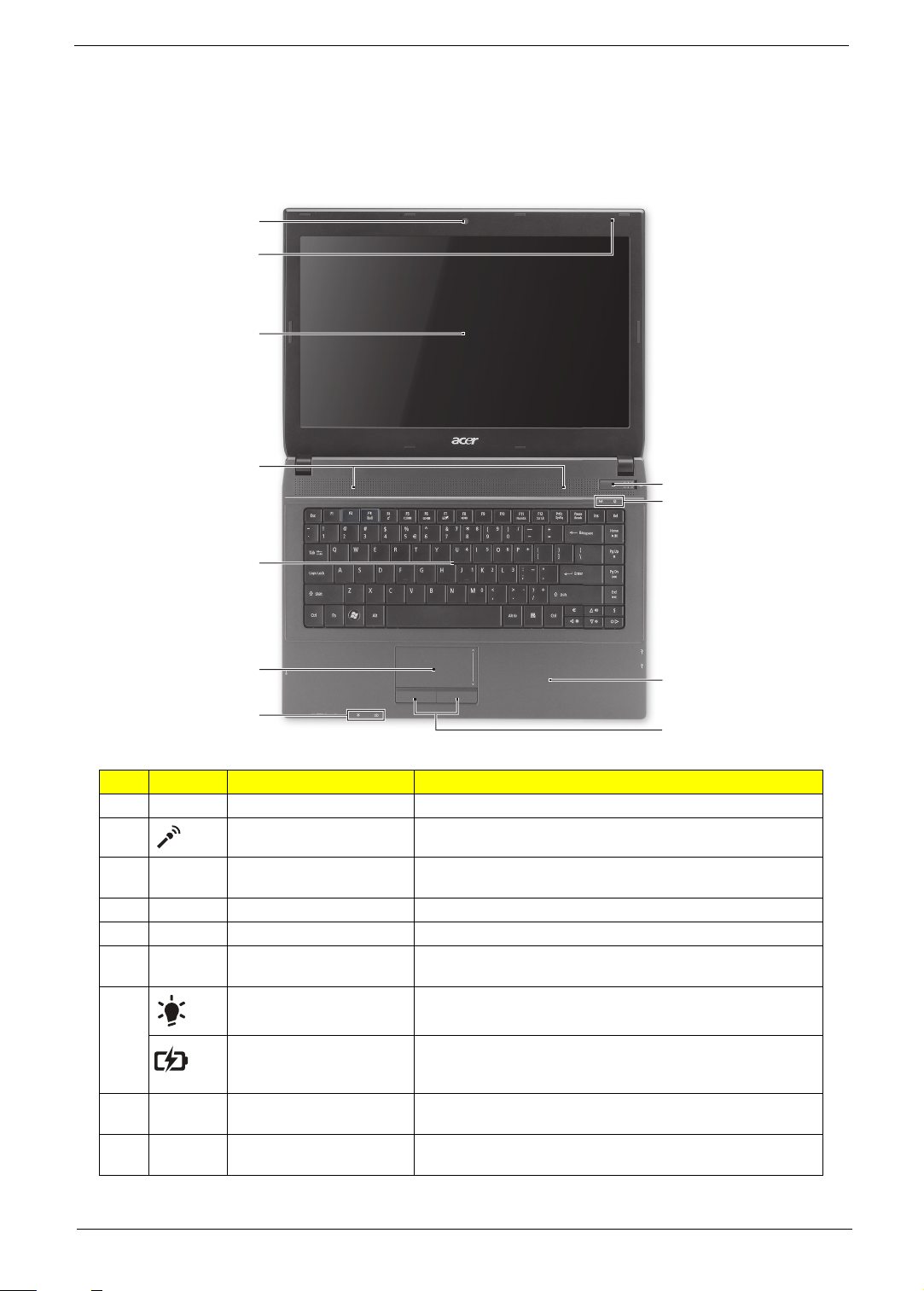
Top View
# Icon Item Description
1 Acer Crystal Eye webcam Web camera for video communication. (only for certain models)
2 Microphone Internal microphone for recording sound.
3 Display screen Also called Liquid-Crystal Display (LCD), displays computer output
(configuration may vary by model).
4 Speakers Left and right speakers deliver stereo audio output.
5 Keyboard For entering data into your computer.
6 Touchpad Touch-sensitive pointing device which functions like a computer
mouse.
7 Power indicator Indicates the computer's power status.
Battery indicator Indicates the computer's battery status.
8 Click buttons (left and right) The left and right buttons function like the left and right mouse
9 Palmrest Comfortable support area for your hands when you use the
Chapter 1 11
1. Charging: The light shows amber when the battery is charging.
2. Fully charged: The light shows blue when in AC mode.
buttons.
computer.
# Icon Item Description
10 Communication indicator Indicates the computer's communication status. (Function may
HDD indicator Indicates when the hard disk drive is active.
11 Power button Turns the computer on and off.
vary by configuration.)
Hotkeys
The computer employs hotkeys or key combinations to access most of the computer's controls like screen
brightness and volume output.
To activate hotkeys, press and hold the <Fn> key before pressing the other key in the hotkey combination.
Hotkey Icon Function Description
<Fn> + <F3> Communication key Enables / disables the computer's communication functions.
<Fn> + <F4> Sleep Puts the computer in Sleep mode.
<Fn> + <F5> Display toggle Switches display output between the display screen,
<Fn> + <F6> Display off Turns the display screen backlight off to save power. Press
<Fn> + <F7> Touchpad toggle Turns the internal touchpad on and off.
(Function may vary by configuration.)
external monitor (if connected) and both.
any key to return.
<Fn> + <F8> Speaker toggle Turns the speakers on and off.
<Fn> + <F11> NumLk Num Lock Turns the embedded numeric keypad on or off.
<Fn> + <F12> Scr Lk Scroll Lock When Scroll Lock is on, the screen moves one line up or
<Fn> + < >
<Fn> + < >
<Fn> + < >
<Fn> + < >
<Fn> +
<Home>
<Fn> + <Pg
Up>
<Fn> + <Pg
Dn>
<Fn> + <End> Next Jump to the next media file.
Brightness up Increases the screen brightness.
Brightness down Decreases the screen brightness.
Volume up Increases the sound volume.
Volume down Decreases the sound volume.
Play/Pause Play or pause a selected media file.
Stop Stop playing the selected media file.
Previous Return to the previous media file.
down when you press the up or down arrow keys
respectively.
Scroll Lock does not work with some applications.
12 Chapter 1
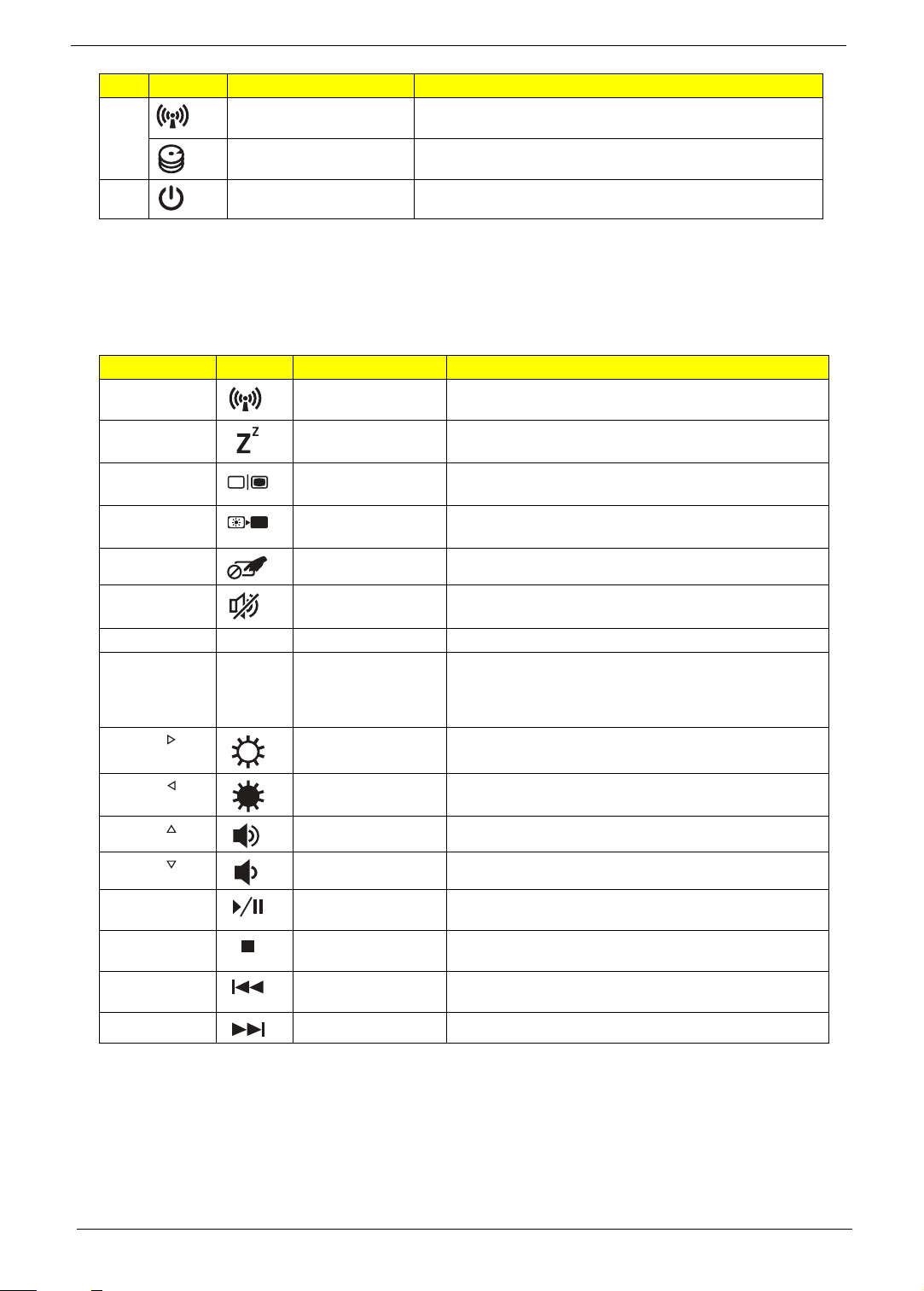
Closed Front View
1
21345
2134567
# Icon Item Description
1 Multi-in-1 card reader Accepts Secure Digital (SD), MultiMediaCard (MMC), Memory Stick
(MS), Memory Stick PRO (MS PRO), xD-Picture Card (xD).
Note: Push to remove/install the card. Only one card can operate at any
given time.
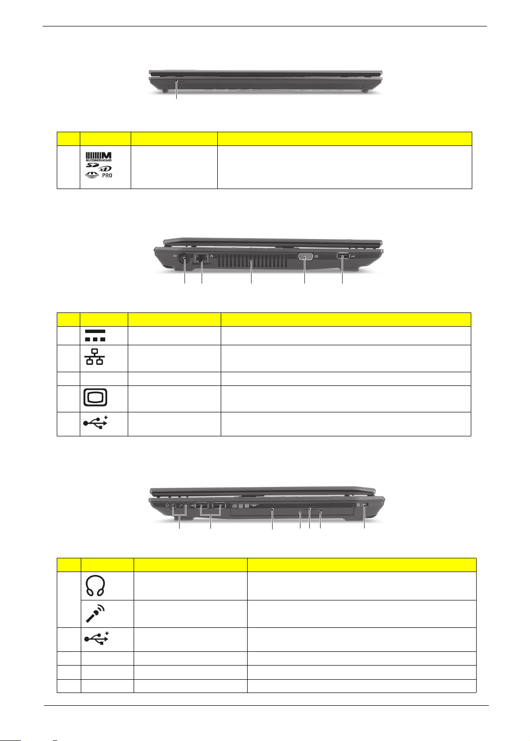
Left View
# Icon Item Description
1 DC-in jack Connects to an AC adapter.
2 Ethernet (RJ-45) port Connects to an Ethernet 10/100/1000-based network.
3 Ventilation slots Enable the computer to stay cool, even after prolonged use.
4 External display (VGA)
5 USB 2.0 port Connect to USB 2.0 devices (e.g., USB mouse, USB camera).
Connects to a display device (e.g., external monitor, LCD projector).
port
Right View
# Icon Item Description
1 Headphones/speaker/line-out
jack with S/PDIF support
Microphone jack Accepts inputs from external microphones.
2 USB 2.0 port Connect to USB 2.0 devices (e.g., USB mouse, USB camera).
3 Optical drive Internal optical drive; accepts CDs or DVDs.
4 Optical disk access indicator Lights up when the optical drive is active.
5 Optical drive eject button Ejects the optical disk from the drive.
Chapter 1 13
Connects to audio line-out devices (e.g., speakers,
headphones).
# Icon Item Description
1
2
3
4
5
6
6 Emergency eject hole Ejects the optical drive tray when the computer is turned off.
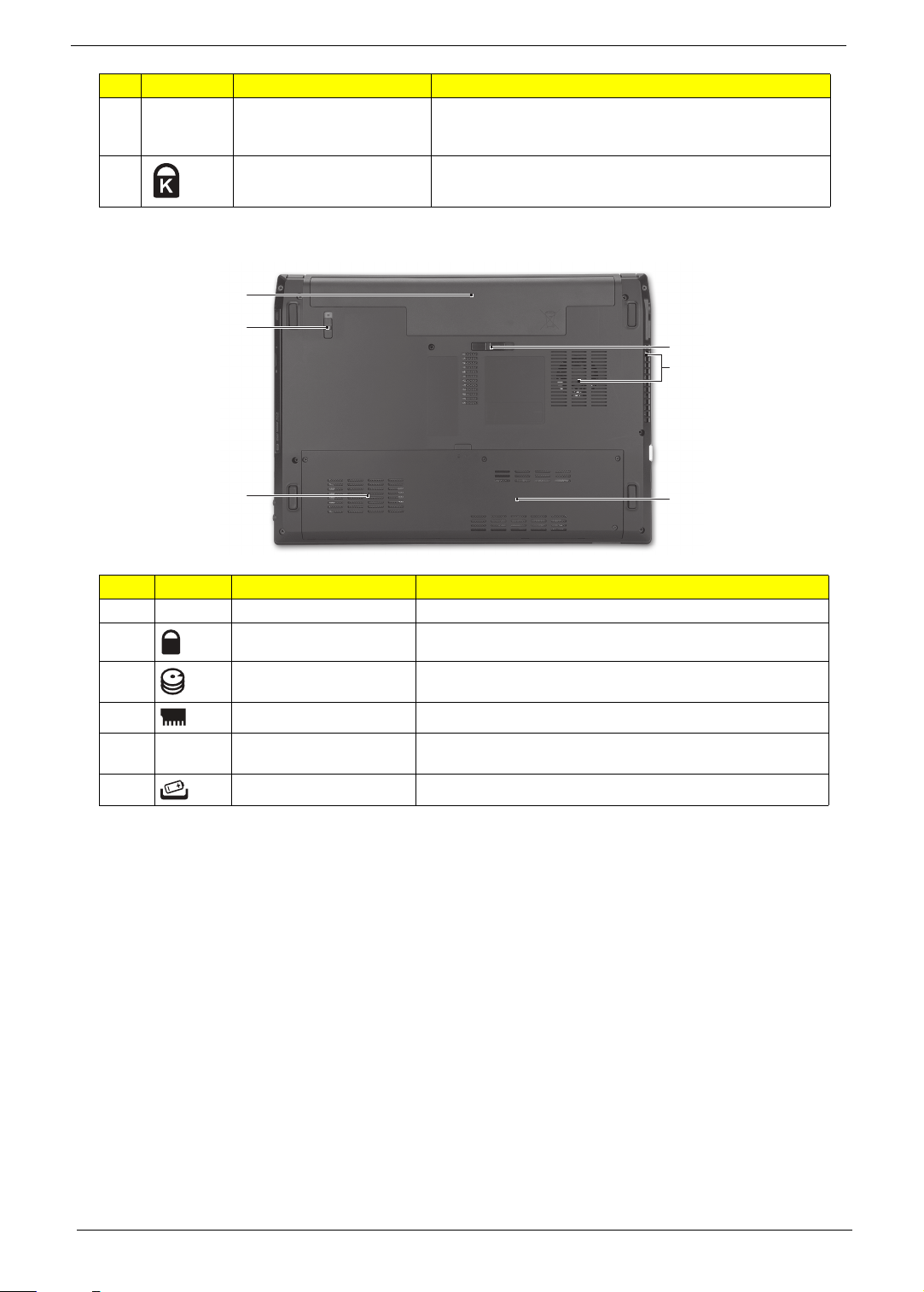
7 Kensington lock slot Connects to a Kensington-compatible computer security lock.
Note: Insert a paper clip to the emergency eject hole to eject the
optical drive tray when the computer is off.
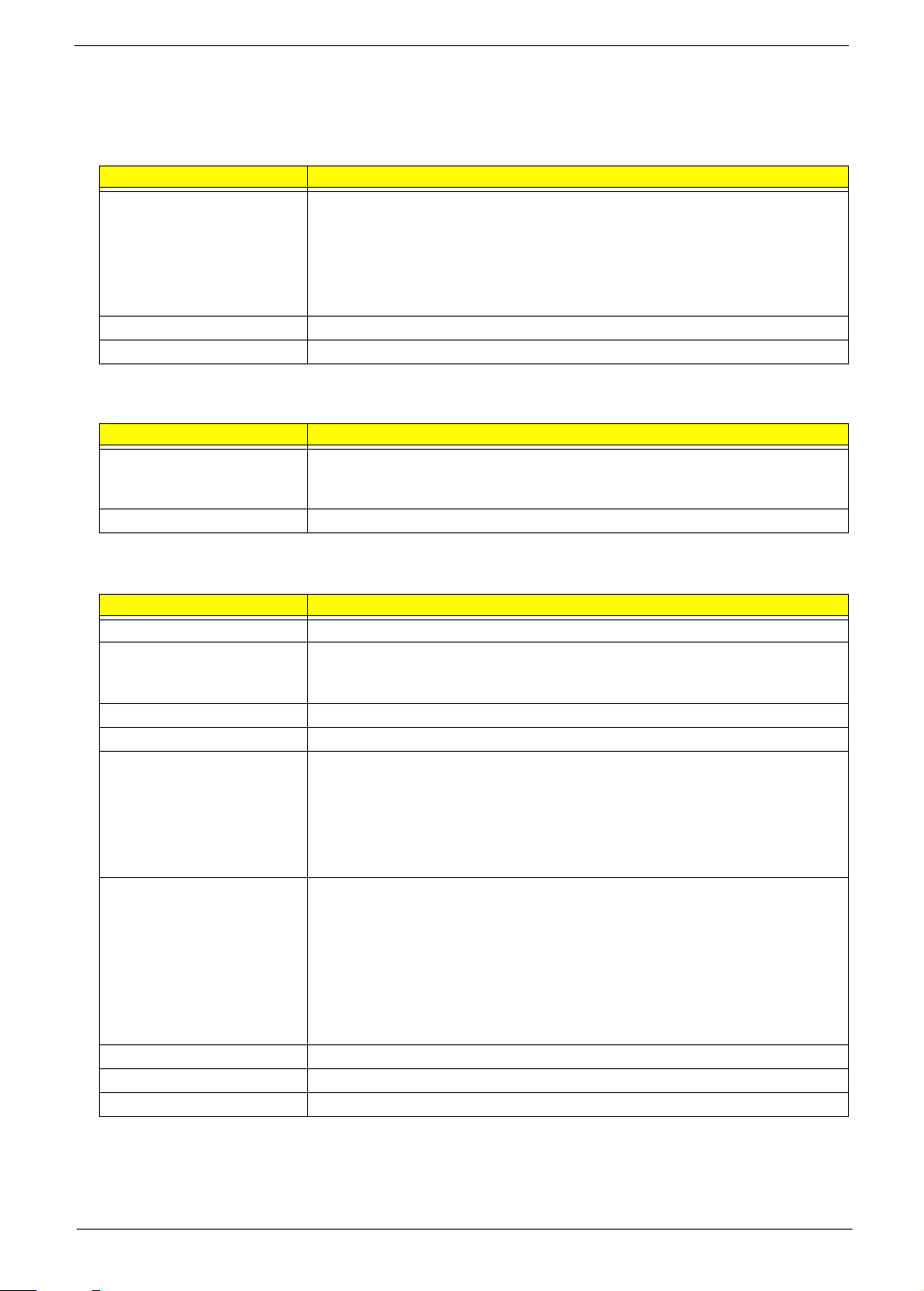
Base View
# Icon Item Description
1 Battery bay Houses the computer's battery pack.
2 Battery release latch Releases the battery for removal.
3 Hard disk bay Houses the computer's hard disk (secured with screws).
4 Memory compartment Houses the computer's main memory.
5 Ventilation slots and cooling
fan
6 Battery lock Locks the battery in position.
Enable the computer to stay cool, even after prolonged use.
Note: Do not cover or obstruct the opening of the fan.
14 Chapter 1
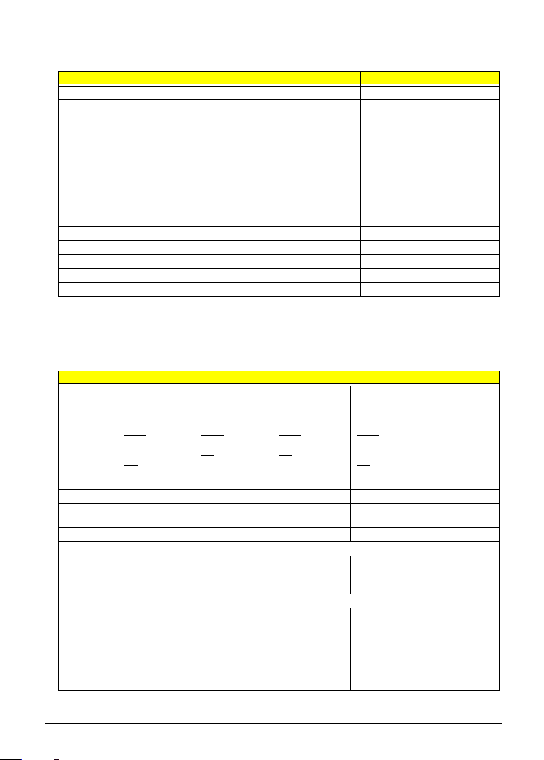
Hardware Specifications and Configurations
Processor
Item Specification
CPU type • Intel Core i5-540M (2.53 GHz)
• Intel Core i5-520M (2.40 GHz)
• Intel Core i5-430M (2.26 GHz)
• Intel Core i3-350M (2.26 GHz)
• Intel Core i3-330M (2.13 GHz)
• Intel Pentium P6000 (1.86 GHz)
Core logic Mobile Intel HM55 Express Chipset
CPU package PGA 988, BGA1288
System Chipsets
Item Specification
North bridge • TravelMate 4740G/4740ZG: NVIDIA N11M-GE1-B-A3 with DDR3-800 512 MB
VRAM NVIDIA N11P-GE1-A3 with DDR3-800 1GB VRAM
• TravelMate 4740/4740Z: Integrated in the Mobile Intel HM55 Express Chipset
South bridge Mobile Intel HM55 Express Chipset
System Controllers
Item Controller
Core logic Mobile Intel HM55 Express Chipset
VGA • TravelMate 4740G/4740ZG: NVIDIA N11M-GE1-B-A3 with DDR3-800 512 MB
VRAM NVIDIA N11P-GE1-A3 with DDR3-800 1GB VRAM
• TravelMate 4740/4740Z: Integrated in the Mobile Intel HM55 Express Chipset
LAN Broadcom BCM57780
3G Ericsson F3307 mobile broadband module 900MHz
Bluetooth • Foxconn Bluetooth BRM 2046 BT2.1 (T60H928.33) f/w:861
• Foxconn Bluetooth ATH AR3011
• Foxconn Bluetooth BRM 2070 (T77H114.01)
• Foxconn Bluetooth BRM 2046 BT3.0 (T60H928.33) f/w:861
• Foxconn Bluetooth ATH AR3011 (BT3.0)
• Foxconn Bluetooth BRM 2070 (T77H114.01) BT 3.0
Wireless 802.11 b/g/n • Foxconn Wireless LAN Atheros HB93 2x2 BGN (HM)
• Liteon Wireless LAN Atheris HB93 2x2 BGN (HM) WN6602AH
• Foxconn Wireless LAN Broadcomm 43225 2x2 BGN (HM) T77H103.00
• Foxconn Wireless LAN Atheros HB97 2x2 BGN (HM)
• Foxconn Wirelss LAN Atheros HB95 1x1 BG (HM)
• LAN Intel WLAN 112BN.HMWG MM#903341
• LAN Intel WLAN INT1000HBG
• LAN Intel WLAN 622AN.HMWG
Memory card reader Alcor AU6433
Audio codec Realtek ALC272
Keyboard ENE3930
Chapter 1 15
BIOS
Item Specification
BIOS vendor Phoenix
BIOS version 1.05
Supported protocols ACPI 1.0b/2.0/3.0 compliance, PCI 2.2, System/HDD Password Security Control, INT
13H Extenstions, PnP BIOS 1.0a SMBIOS 2.4, BIOS Boot Specification, Simple Boot
Flag 1.0, Boot Block, PCI Bus Power Management Interface Specification, USB
Specification 1.1/2.0, IEEE 1394 1.0, USB/1394 CD-ROM Boot Up support, PC Card
Standard 1995 (PCMCIA 3.0 Compliant Device), IrDA 1.0, Intel AC97 CNR
Specification, WfM 2.0, PXE 2.1, Boot Integrity Service Application Program Interface
(BIS) 1.0, PC99a and Mobile PC2001 Compliant
Video
Item Specification
Chipset • TravelMate 4740G/4740ZG: NVIDIA N11M-GE1-B-A3 with DDR3-800 512 MB
VRAM NVIDIA N11P-GE1-A3 with DDR3-800 1GB VRAM
• TravelMate 4740/4740Z: Integrated in the Mobile Intel HM55 Express Chipset
Memory size • TravelMate 4740G/4740ZG model: DDR3-800 512 MB or 1GB VRAM
Ethernet
Item Specification
LAN Chipset Broadcom BCM57780
Supports LAN protocol 10/100/1000 Mbps
LAN connector type RJ45
LAN connector location Left side
Features • Integrated 10/100 BASE-T transceiver
• Wake on LAN support compliant with ACPI 2.0
•PCIE
Wireless LAN
Item Specification
Chipset • Foxconn Wireless LAN Atheros HB93 2x2 BGN (HM)
• Liteon Wireless LAN Atheris HB93 2x2 BGN (HM) WN6602AH
• Foxconn Wireless LAN Broadcomm 43225 2x2 BGN (HM) T77H103.00
• Foxconn Wireless LAN Atheros HB97 2x2 BGN (HM)
• Foxconn Wirelss LAN Atheros HB95 1x1 BG (HM)
• LAN Intel WLAN 112BN.HMWG MM#903341
• LAN Intel WLAN INT1000HBG
• LAN Intel WLAN 622AN.HMWG
Protocol 802.11 b/g/n
Interface PCI Express mini-card
3G Module
Item Specification
Chipset Ericsson F3307 mobile broadband module 900MHz
Data Speeds • HSPA Data speed — D/L 7.2Mbps, U/L 2.0Mbps
• EDGE/GPRS Data speed — D/L: 247.4Kbps, U/L: 123.7Kbps
Interface PCI Express mini-card
16 Chapter 1
Bluetooth
Item Specification
Chipset • Foxconn Bluetooth BRM 2046 BT2.1 (T60H928.33) f/w:861
• Foxconn Bluetooth ATH AR3011
• Foxconn Bluetooth BRM 2070 (T77H114.01)
• Foxconn Bluetooth BRM 2046 BT3.0 (T60H928.33) f/w:861
• Foxconn Bluetooth ATH AR3011 (BT3.0)
• Foxconn Bluetooth BRM 2070 (T77H114.01) BT 3.0
Data throughput Up to 24 Mbps
Protocol Bluetooth 2.1
Interface USB 2.0
Connector type USB
System Memory
Item Specification
Memory controller Built-in
Vendor & model name Elpida
• SO-DIMM DDRIII 1066 1GB EBJ10UE8BDS0-AE-F LF 128*8 0.065um
• SO-DIMM DDRIII 1333 1GB EBJ10UE8BDS0-DJ-F LF 128*8 0.065um
• SO-DIMM DDRIII 1066 2GB EBJ21UE8BDS0-AE-F LF 128*8 0.065um
• SO-DIMM DDRIII 1333 2GB EBJ21UE8BDS0-DJ-F LF 128*8 0.065um
• SO-DIMM DDRIII 1333 4GB EBJ41UF8BAS0-DJ-F LF 256*8 0.055um
Hynix
• SO-DIMM DDRIII 1333 1GB HMT112S6TFR8C-H9 LF 128*8 0.055u
• SO-DIMM DDRIII 1333 2GB HMT125S6TFR8C-H9 LF 128*8 0.055um
Kingston
•
Micron
• SO-DIMM DDRIII 1066 1GB MT8JSF12864HZ-1G1F1 LF 128*8 0.065um
• SO-DIMM DDRIII 1066 2GB MT16JSF25664HZ-1G1F1 LF 128*8 0.065um
Nanya
• SO-DIMM DDRIII 1333 2GB NT2GC64B8HC0NS-CG LF 128*8 0.065um
Samsung
• SO-DIMM DDRIII 1066 1GB M471B2873EH1-CF8 LF 64*16 0.055um
• SO-DIMM DDRIII 1333 1GB M471B2873FHS-CH9 LF 128*8 46nm
• SO-DIMM DDRIII 1066 2GB M471B5673EH1-CF8 LF 128*8 0.055um
• SO-DIMM DDRIII 1333 2GB M471B5673FH0-CH9 LF 128*8 46nm
• SO-DIMM DDRIII 1333 4GB M471B5273CH0-CH9 LF 256*8 46nm
Memory size 0 MB (no on-board memory)
SO-DIMM socket number 2 sockets
Supports memory size per
socket
Supports maximum memory
size
Supports SO-DIMM type DDR3 synchronous DRAM
Supports DIMM Speed 1066/1333 MT/s
Supports SO-DIMM package 204-pin SO-DIMM
Memory module combinations You can install memory modules in any combinations as long as they match the above
4 GB
8 GB
specifications.
Chapter 1 17
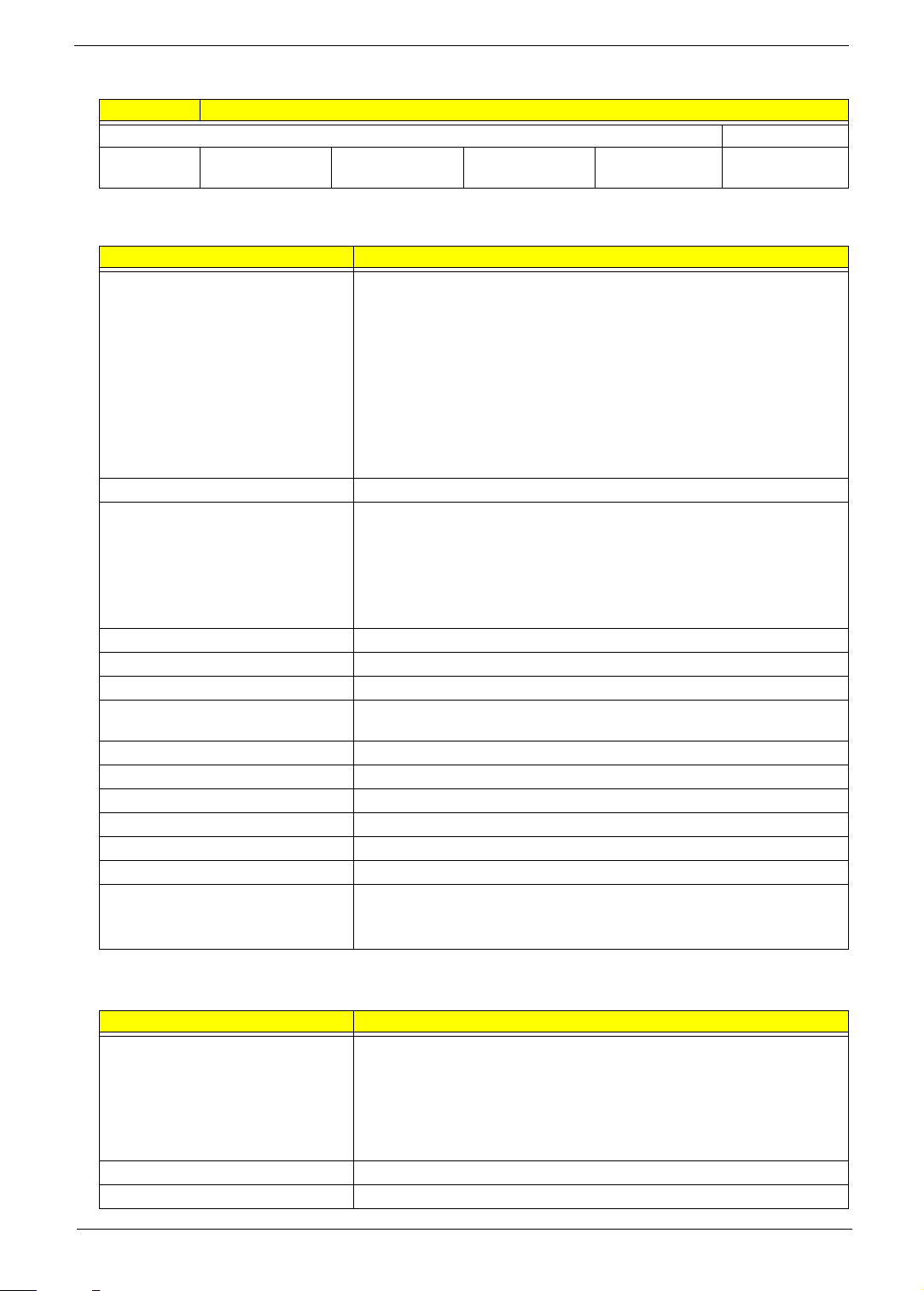
Memory Combinations
Slot 1 Slot 2 Total M e m ory
0 GB 1 GB 1 GB
0 GB 2 GB 2 GB
0 gb 4 GB 4 GB
1 GB 0 GB 1 GB
1 GB 1 GB 2 GB
1 GB 2 GB 3 GB
1 GB 4 GB 5 GB
2 GB 0 GB 2 GB
2 GB 1 GB 3 GB
2 GB 2 GB 4 GB
2 GB 4 GB 5 GB
4 GB 0 GB 4 GB
4 GB 1 GB 5 GB
4 GB 2 GB 6 GB
4 GB 4 GB 8 GB
NOTE: Above table lists some system memory configurations. You may combine DIMMs with various
capacities to form other combinations. On above table, the configuration of slot 1 and slot 2 could be
reversed.
Hard Disk Drive
Item Specification
Vendor &
Model Name
Capacity (GB) 160 250 320 500 640
Bytes per
sector
Data heads 3/4 4 4 4 4
Drive Format
Disks 2 1 2 2 2
Spindle speed
(RPM)
Performance Specifications
Buffer size
(MB)
In terf ace SATA S ATA SATA SATA SATA
Max. media
transfer rate
(disk-buffer,
Mbytes/s)
Seagate
ST9160314AS
To sh i b a
MK1665GSX
HGST
HTS545016B9A30
0
WD
WD1600BEVT22A23T0
512 512 512 512 512
5400 5400 5400 5400 5400
88 8 88
540 540 850 3.0 GB/s Max.
Seagate
ST9250315AS
To sh ib a
MK2565GSX
HGST
HTS545025B9A300
WD
WD2500BEVT22A23T0
Seagate
ST9320325AS
To sh ib a
MK3265GSX
HGST
HTS545032B9A300
WD
WD3200BEVT22A23T0
Seagate
ST9500325AS
To sh i ba
MK5065GSX
HGST
HTS545050B9A30
0
WD
WD5000BEVT22A0RT0
Buffer to Host
To sh i b a
MK6465GSX
WD
WD6400BEVT22A0RT0
3.0 GB/s
18 Chapter 1
Hard Disk Drive
Item Specification
DC Power Requirements
Voltage
tolerance
5V (DC) +/- 5% 5V (DC) +/- 5% 5V (DC) +/- 5% 5V (DC) +/- 5% 5V (DC) +/- 5%
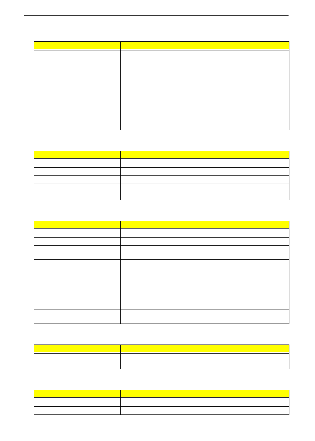
LCD Panel
Item Specification
Vendor & model name AUO
• 14" WXGA None Glare B140XW01 V9 0A LF 200nit 8ms 400:1
• 14" WXGA Glare B140XW01 V8 0A LF 220nit 8ms 500:1 (power saving)
LG
• 14" WXGA Glare LP140WH1-TLA2 LF 220nit 8ms 500:1
Samsung
• 14" WXGA None Glare LTN140AT01-001 LF 220nit 8ms 300:1
• 14" WXGA Glare LTN140AT01-G03 LF 220nit 8ms 500:1
CMO
• 14" WXGA Glare N140B6-L02 C2 LF 220nit 8ms 400:1
Screen Diagonal 14 inches
Resolution support • 1366 x 768
• 1360 x 768
• 1280 x 768
• 1280 x 720
• 1024 x 768
• 800 x 600
Pixel Pitch (mm) 0.2265
Pixel Arrangement R.G.B. Vertical Stripe
Display Mode Normally White
Typical White Luminance (NIT)
also called Brightness
Contrast Ratio 500:1
Response Time msec 8
Power consumption (W) 3.8 - 4.2
Viewing Angle (U/D/R/L) 20/45/45/45
Interface 1ch LVDS
Supply voltage (V) 3.3
Temperature Range( C)
Operating
Storage (shipping)
200 - 220
0 to +50
-40 to +60
Webcam
Item Specification
Vendor & model name Chicony
• CH9665SN (CNF9157)
Suyin
• SY9665SN
Liteon
• LT6AASP (09P2BF127)
Resolution 1.3 M
DV capability Yes
Chapter 1 19
AC Adapter
Item Specification
Vendor Delta
• 65 W ADP-65JH DB
• 90 W ADP-90CD DB
Liteon
• 65 W PA-1650-22AC
• 90 W PA-1900-34AR
Hipro
• 65 W HP-A0652R3B
• 90 W HP-A0904A3 B1LF
Input 90 - 264 Vac
Output 19 V / 3.42 - 4.74 A
Battery Pack
Item Specification
Vendor Panasonic/Sanyo/Sony/Simplo
Battery Type Li-ion
Pack capacity 6-cell 4400 mAh
Number of battery cell 6
Package configuration 3 cells in series, 2 series in parallel
System Power Management
ACPI mode Power Management
Mech. Off (G3) All devices in the system are turned off completely.
Soft Off (G2/S5) OS initiated shutdown. All devices in the system are turned off completely.
Working (G0/S0) Individual devices such as the CPU and hard disc may be power managed in
this state.
Suspend to RAM (S3) • CPU set power down
• VGA Suspend
• PCMCIA Suspend
• Audio Power Down
• Hard Disk Power Down
• CD-ROM Power Down
• Super I/O Low Power mode
Save to Disk (S4) Also called Hibernation Mode. System saves all system states and data onto
the disc prior to power off the whole system.
Physical Specifications
Item Specification
Dimension (W×D×H) 343mm x 245mm x 26.1 - 32.6mm
Weight < 2.2kg
Environmental Requirements
Item Specification
Operating temperature 5 to 35 °C (41 to 95 °F)
Operating humidity 20% to 80% RH non-condensing
20 Chapter 1

Chapter 1 21

22 Chapter 1

Chapter 2
System Utilities
Phoenix SecureCore Setup Utility
Phoenix SecureCore Setup Utility is a hardware configuration program built into your system's Basic Input/
Output System (BIOS). Since most systems are already properly configured and optimized, there is normally
no need to run this utility.
You will need to run this utility under the following conditions:
• When changing the system configuration including:
• Setting the system time and date
• Configuring the hard drives
• Specifying the boot device sequence
• Configuring the power management modes
• Setting up system passwords or making other changes to the security setup
• When a configuration error is detected by the system and you are prompted ("Run Setup" message) to
make changes to the BIOS settings.
IMPORTANT: If you repeatedly receive “Run Setup” messages, the RTC battery located on the mainboard
(RTC1) may be defective. In this case, the system cannot retain configuration values in CMOS.
Replace the RTC battery with a new one.
NOTE: For ease of reading, Phoenix SecureCore Setup Utility will be simply referred to as “Setup” or “Setup
Utility” in this Service Guide.
In the descriptive tables following each of the menu screen illustrations, settings in boldface are the
default and suggested parameter settings.
The Setup Utility loads the configuration values in a battery-backed nonvolatile memory called CMOS RAM.
This memory area is not part of the system RAM, which allows configuration data to be retained when power is
turned off. The values take effect when the system is booted. POST uses these values to configure the
hardware. If the values and the actual hardware do not agree, POST generates an error message. You must
run this utility to change the BIOS settings from the default or current configuration.
Chapter 2 23

Accessing the Setup Utility
Phoenix SecureCore(tm) Setup Utility
CPU Type:
CPU Speed:
IDE0 Model Name:
I D E0 S e ri a l Nu mb er :
ATAPI Model Name:
System BIOS Version:
VGA BIOS Version:
KBC Version:
Serial Number:
Asset Tag Number:
Product Name:
Manufacturer Name:
UUID:
I n te l ( R) C o re ( TM ) i5 C PU M 4 3 0 @2 .2 7 GH z
100217PBPC061DCAKXLL
Optiarc DVD RW AD-7585H-(S5)
V1.04
70.18.49.00.07
01.05
914JD01002G009B01EB2000
No Asset Tag
TravelMate 4740
Acer
373dd280-2d84-11df-9ce1-b8c80ef75913
2260 MHZ
Hitachi HTS545032B9A300-(S1)
F1
Esc
Help
Exit
Select Item
Select Menu
Change Values
Select Sub-Menu
F5/F6
Enter
F9
F10
Setup Defaults
S a ve a n d Ex it
Security Boot ExitMainInformation
1. Turn on the system.
If the system is already turned on, save your data and close all open applications, then restart the
computer.
2. During POST, press <F2>.
If you fail to press <F2> before POST is completed, you will need to restart the computer. Use the left and
right arrow keys to move between selections on the menu bar
24 Chapter 2

Navigating through the Setup Utility
Use the keys listed in the legend bar on the bottom of the Setup screen to work your way through the various
menu and submenu screens of the Setup Utility. The table below lists these legend keys and their respective
functions.
Key Function
Left and Right
arrow
Up and Down
arrow
F5 and F6 To select a value for the currently selected field (only if it is user-configurable). Press these
Enter To select a field value (a pop-up menu displays) or submenu screen.
Esc If you press this key:
F1 or Alt-H To bring up the General Help
F9 Press to load default system values.
F10 Press to save changes and close the Setup Utility.
To move between selections on the menu bar.
To move the cursor to the field you want.The currently selected field will be highlighted. The
right side of each menu screen displays a field help panel—Item Specific Help
panel displays the help text for the currently selected field. It updates as you move the cursor
to each field.
To view a submenu screen, use the up and down keys to move the cursor to the submenu you
want, then press Enter.
keys repeatedly to display all possible entries. A parameter that is enclosed in square
brackets [ ] is user-configurable. Grayed-out parameters are not user-configurable for one of
the following reasons:
The field value is auto-configured or auto-detected.·
The field value is informational only.
The field is password-protected.
On one of the primary menu screens, the Exit menu displays.
On a submenu screen, the previous screen displays.
When you are making selections from a pop-up menu, closes the pop-up without making
a selection.
window. The General Help window describes other Setup
navigation keys that are not displayed on the legend bar.
panel. This
BIOS Setup Utility Menus
The Setup Utility has five menus for configuring the various system functions. These include:
• Information
•Main
• Security
• Boot
• Exit
IMPORTANT: The screenshots used in this section are for illustration only. The values displayed may not be
the same as those in your system. Actual screen information varies by model, installed features, and
location.
In the descriptive table following each of the screenshot, settings in boldface are the default settings.
Chapter 2 25

Information
Phoenix SecureCore(tm) Setup Utility
CPU Type:
CPU Speed:
IDE0 Model Name:
I D E0 S er ia l Nu mb er :
ATAPI Model Name:
System BIOS Version:
VGA BIOS Version:
KBC Version:
Serial Number:
Asset Tag Number:
Product Name:
Manufacturer Name:
UUID:
I n te l (R ) Co re ( TM ) i5 C PU M 4 30 @ 2. 27 G Hz
100217PBPC061DCAKXLL
Optiarc DVD RW AD-7585H-(S5)
V1.04
70.18.49.00.07
01.05
914JD01002G009B01EB2000
No Asset Tag
TravelMate 4740
Acer
373dd280-2d84-11df-9ce1-b8c80ef75913
2260 MHZ
Hitachi HTS545032B9A300-(S1)
F1
Esc
Help
Exit
Select Item
Select Menu
Change Values
Select Sub-Menu
F5/F6
Enter
F9
F10
Setup Defaults
S a ve a nd E xi t
Security Boot ExitMainInformation
The Information menu displays a summary of your system hardware information. These information are
necessary for troubleshooting and may be required when asking for technical support.
Parameter Description
CPU Type Displays the processor model and speed.
CPU Speed Displays the processor speed.
IDE0 Model Name Displays the model name of the hard drive installed on the primary IDE master.
IDE0 Serial Number Displays the serial number of the hard drive installed on the primary IDE master.
ATAPI Model Name Displays the model name of the installed optical drive.
System BIOS Version Displays system BIOS version.
VGA BIOS Version Displays the VGA firmware version of the system.
KBC Version Displays the keyboard controller version.
Serial Number Displays the system serial number.
Asset Tag Number Displays the system asset tag number.
Product Name Displays the official model name of the system.
Manufacturer Name Displays the name of the system manufacturer.
UUID Displays the system’s UUID (universally unique identifier). UUID is an identifier standard
used in software construction, standardized by the Open Software Foundation (OSF) as
part of the Distributed Computing Environment (DCE).
26 Chapter 2

Main
Phoenix SecureCore(tm) Setup Utility
Item Specific Help
<Tab>, <Shift-Tab>, or
<Enter> selects field.
System Time:
System Date:
Total Memory:
Video Memory:
Quiet Boot:
Network Boot:
F12 Boot Menu:
D2D Recovery:
SATA Mode:
F1
Esc
Help
Exit
Select Item
Select Menu
Change Values
Select Sub-Menu
F5/F6
Enter
F9
F10
Setup Defaults
S a ve a nd E xi t
[]
[]
:05:48
03/19/2010
3072 MB
512 MB
[Enabled]
[Enabled]
[Disabled]
[Enabled]
[AHCI Mode]
10
Boot ExitMainInformation Security
Use the Main menu to set the system time and date, and other basic options.
System Time Displays the system time. The time is expressed in a 24-hour
System Date Displays the system date. MM/DD/YYYY
Total Memory Displays the size of system memory detected during boot-up.
Video Memory Displays the size of video memory detected during boot-up.
Quiet Boot Enables or disables the Quiet Boot function.
Network Boot When enabled, a remote host with appropriate boot image
F12 Boot Menu Enables or disables the Boot menu during POST. Enabled
D2D Recovery Enables or disables the D2D Recovery function. This function
SATA Mode Select the SATA controller operating mode.
Parameter Description Format/Options
HH:MM:SS
format.
When enabled, BIOS setup is in graphical mode and displays
only the system brand logo during POST and while booting.
When disabled, BIOS setup is in conventional text mode and
displays the system Summary Screen.
can boot this system. (only works with an Ethernet device.)
(hour:minute:second)
(month/day/year)
Enabled
Disabled
Enabled
Disabled
Disabled
Enabled
Disabled
AHCI
IDE
allows the user to create a hidden partition on the hard drive
to store the operation system. User can then use this partition
to restore the system to factory defaults by pressing the <Alt>
+ <F10> keys during system boot-up.
When set to AHCI (Advanced Host Controller Interface), the
SATA controller enables its AHCI and RAID features when the
system boots up.
When set to IDE, the SATA controller disables its AHCI and
RAID functions when the system boots up.
Note: If you do not intend to use the AHCI or RAID features
set this parameter to IDE to speed up the boot-up time.
Chapter 2 27

Security
Phoenix SecureCore(tm) Setup Utility
Item Specific Help
Supervisor Password
c o nt ro ls a cc es s of t he
whole setup utility.
I t c an b e us ed t o bo ot
u p w he n Pa ss wo rd o n
boot is enabled.
S u pe rv is or P as sw or d Is :
U s er P as sw or d Is :
H D D Pa ss wo rd I s:
S e t Us er P as sw or d
S e t HD D Pa ss wo rd
P a ss wo rd o n Bo ot :
Set Supervisor Password
F1
Esc
Help
Exit
Select Item
Select Menu
Change Values
Select Sub-Menu
F5/F6
Enter
F9
F10
Setup Defaults
S a ve a nd E xi t
Clear
Clear
Clear
[Enter]
[Enter]
[Disabled]
[]Enter
Boot ExitMainInformation Security
Use the Security menu option to set system passwords to protect your system from unauthorized use.
Parameter Description Option
Supervisor Password Is Displays the supervisor password status. Clear
User Password Is Displays the user password status. Clear
HDD Password Is Displays the hard drive password status. Clear
Set Supervisor Password Press Enter to set a supervisor password. When set, this password will allow the
Set User Password Press Enter to set a user password. When set, this password will restrict a user’s
Set HDD Password Press Enter to set password for accessing the hard disk drive (HDD) password. It
Password on Boot Referred to as the power-on password. When enabled, the
CAUTION: When you are prompted to enter a password, you have three tries before the system halts. Don’t
forget your password.
Set
Set
Set
user to access and change all settings in the Setup Utility.
access to the Setup menus. Only the following menus will be accessible:
• System Time and System Date
• All Exit menu options excluding Load Setup Defaults
Note: A supervisor password must first be set before creating a user password.
If Password on Boot is enabled, the user must enter the user password each time
the notebook is turned on or wakes from Sleep.
will be required during boot-up or when waking from hibernation mode.
user or supervisor password will be required to boot up the
system.
Note: A supervisor password must first be set before
creating a user password.
Enabled
Disabled
28 Chapter 2

Setting a Password
HDD password error code
[15494]
Follow these steps as you set the user, the supervisor, or the HDD password:
1. Use the up/down keys to select a password parameter (Set Supervisor Password, Set User Password, or
Set HDD Password), then press Enter. A Password box will appear.
2. Type a password then press Enter.
The password may consist of up to 8 alphanumeric characters (A-Z, a-z, 0-9, not case sensitive).
3. Retype the password to verify the first entry then press Enter again.
4. Press <F10>.
5. Select Yes to save the new password and close the Setup Utility.
Changing a Password
Follow these steps as you change the user, the supervisor, or the HDD password:
1. Use the up/down keys to select a password parameter (Set Supervisor Password, Set User Password, or
Set HDD Password), then press Enter.
2. Type the current password then press Enter.
3. Type a new password then press Enter.
4. Retype the new password to verify the first entry then press Enter.
You will be prompted to save the new password.
5. Press Enter.
6. Press <F10> to save the password and close the Setup Utility or you can proceed to setting a user
password.
Removing a User and Supervisor Password
1. Use the up/down keys to select a password parameter (Set Supervisor Password, Set User Password, or
Set HDD Password), then press Enter.
2. Enter the current password then press Enter.
3. Press Enter twice without entering anything in the New Password and Confirm New Password fields.
4. After doing this, the system automatically sets the related password parameter to Clear.
Removing a HDD Password
If you key in the wrong HDD password thrice, the “HDD password error code” will appear on the screen. .
To regain access to your system if you lose the HDD password, you need to generate a master password and
unlock the hard drive. Go to page 86 for instructions.
Chapter 2 29

Resetting a Password
If you have forgotten the user password, the system will continue to function normally but you will have limited
access to the Setup Utility.
If you have enabled the Password on Boot field and you forget the supervisor password, you will not be able to
boot up the system. The same thing applies if you forget the HDD password.
To clear a lost user or supervisor password you need to short the clear password hardware gap located on the
mainboard. Go to page 85 for instructions.
30 Chapter 2

Boot
Phoenix SecureCore(tm) Setup Utility
Item Specific Help
U s e < > or < > t o
select a device, then
p r es s <F 6> t o mo ve i t
u p t he l is t, o r <F 5>
t o m ov e it d ow n th e
list. Press <Esc> to
escape the menu.
Boot priority order:
F1
Esc
Help
Exit
Select Item
Select Menu
Change Values
Select Sub-Menu
F5/F6
Enter
F9
F10
Setup Defaults
S a ve a nd E xi t
2: IDE CD/DVD: Optiarc DVD RW AD-7585H-(S
3 : N et wo rk B oo t: M BA v 12 .2 .2 S lo t 03 00
4 : U SB H DD :
5 : U SB F DD :
6 : U SB K ey :
7 : U SB C D/ DV D:
1: IDE0: Hitachi HTS545032B9A300-(S1)
Boot ExitMainInformation Security
Use the Boot menu to set the preferred drive sequence in which the Setup Utility attempts to boot the
operating system.
To set boot drive sequence:
1. Press the up or down arrow keys to select a bootable device.
2. Press <F5> or <F6> to move the selected device up or down the boot sequence.
3. Press <F10> to save the changes you made and close the Setup Utility.
Chapter 2 31

Exit
Phoenix SecureCore(tm) Setup Utility
Main
Item Specific Help
E x it S ys te m Se tu p an d
save your changes to
CMOS.
F1
Esc
Help
Exit
Select Item
Select Menu
Change Values
Select Sub-Menu
F5/F6
Enter
F9
F10
Setup Defaults
S a ve a nd E xi t
Information
Exit Discarding Changes
Load Setup Defaults
Discard Changes
Save Changes
Exit Saving Changes
Boot ExitSecurity
The Exit menu lists options for quitting from the BIOS Setup Utility.
Parameter Description
Exit Saving Changes Save changes made and closes the utility.
Exit Discarding Changes Discards changes made and closes the utility.
Load Setup Defaults Loads the factory default settings for all Setup parameters.
Discard Changes Discards all changes made to the utility and loads previous configuration settings.
Save Changes Save all changes made to the utility.
Keyboard shortcut: F10
Keyboard shortcut: F9
32 Chapter 2

Updating the BIOS
The BIOS flash memory update is required for the following conditions:
• New versions of system programs
• New features or options
• Restore a BIOS when it becomes corrupted.
NOTE: Observe the following when using the Flash utility to update the system BIOS flash ROM.
- If you do not have a Crisis Recovery disk at hand, then you should create a Crisis Recovery Disk
(See “Creating the BIOS Crisis Recovery Disk in Windows” on page 87) before you use the Flash
utility.
- Do not install memory-related drivers (XMS, EMS, DPMI) when you use the Flash utility.
- Make sure the battery pack is installed to the system and that the system is connected to a UPS unit
when you run the Flash utility. If the battery pack does not contain enough power to finish BIOS flash,
the system may not boot because the BIOS is not completely loaded.
Chapter 2 33

34 Chapter 2

Machine Disassembly and Replacement
This chapter contains step-by-step procedures on how to disassemble the notebook computer for
maintenance and troubleshooting.
Disassembly Requirements
To disassemble the notebook computer, you need the following tools:
• Wrist grounding strap and conductive mat for preventing electrostatic discharge
• Flat screwdriver
• Philips screwdriver
• Hex screwdriver
• Plastic flat screwdriver
• Plastic tweezers
NOTE: The screws for the different components vary in size. During the disassembly process, group the
screws with the corresponding components to avoid mismatch when putting back the components.
Chapter 3
Chapter 3 35

General Information
Pre-disassembly Instructions
Before proceeding with the disassembly procedure, make sure that you do the following:
1. Turn off the system and all peripherals.
2. Unplug the AC adapter and all power and signal cables from the system.
3. Place the system on a flat, stable surface.
4. Remove the battery pack.
Disassembly Process
The disassembly process is divided into the following stages:
• External module disassembly
• Main unit disassembly
• LCD module disassembly
The flowcharts provided in the succeeding disassembly sections illustrate the entire disassembly sequence.
Observe the order of the sequence to avoid damage to any of the hardware components. For example, if you
want to remove the mainboard, you must first remove the keyboard, then disassemble the inside assembly
frame in that order.
Main Screw List
Code Type Color Part No.
A M2 x L5 Black 86.00M90.525
B M2 x L3 Black 86.00F80.723
C M3 x L4 Silver 86.9A524.4R0
D M2.5 x L6 Black 86.00E33.736
E M2 x L2 Black 86.00E09.622
F M2.5 x L5 Black 86.00F87.735
G M2.5 x L4 Black 86.00H36.534
36 Chapter 3

External Module Disassembly Process
External Modules Disassembly Flowchart
The flowchart below gives you a graphic representation on the entire disassembly sequence and instructs you
on the components that need to be removed during servicing. For example, if you want to remove the
mainboard, you must first remove the keyboard, then disassemble the inside assembly frame in that order.
Screw List
Code Part Number Type Color
A 86.00M90.525 M2 x L5 Black
B 86.00F80.723 M2 x L3 Black
C 86.9A524.4R0 M3 x L4 Silver
Chapter 3 37

Removing the Battery Pack
1. Turn base unit over.
2. Slide the battery lock to the unlock position.
3. Slide and hold the battery release latch to the release position.
4. Remove the battery pack out of the unit.
IMPORTANT: The battery is highlighted with a yellow oval in the above image. Follow local
regulations for battery disposal.
Removing the Card Reader Dummy Card
1. See “Removing the Battery Pack” on page 38.
2. Push against the card, as if you were pushing it further into the slot, letting the card spring out.
3. Remove the card from the slot.
38 Chapter 3

Removing the Back Cover
1. See “Removing the Battery Pack” on page 38.
2. Loosen the four captive screws (A) securing the back cover. These screws cannot be removed.
Typ e Quantity Color Torque Part No.
M2 x L5 4 Black 1.6 kgf-cm 86.00M90.525
3. Insert a plastic scribe on the cover’s notch to release the cover, then remove the cover.
Removing the Hard Disk Drive Module
1. See “Removing the Battery Pack” on page 38.
2. See “Removing the Back Cover” on page 39.
Chapter 3 39

3. Remove the screw (B) securing the hard disk drive module.
Typ e Quantity Color Torque Part Number
M2 x L3 1 Black 1.6 kgf-cm 86.00F80.723
4. Grasp the black mylar tab and use it to disengage the hard drive from its connector, then remove the drive
from its compartment.
NOTE: To prevent damage to device, avoid pressing down on it or placing heavy objects on top of it.
5. Remove the two screws (C) securing the hard disk drive bracket.
Typ e Quantity Color Torque Part Number
M3 x L4 2 Silver 3.0 kgf-cm 86.9A524.4R0
40 Chapter 3

6. Detach the bracket from the hard disk.
Removing the DIMM Modules
1. See “Removing the Battery Pack” on page 38.
2. See “Removing the Back Cover” on page 39.
3. Push out the latches on both sides of the DIMM socket to release the DIMM and remove the DIMM
modules.
Removing the WLAN Module
1. See “Removing the Battery Pack” on page 38.
2. See “Removing the Back Cover” on page 39.
3. Detach the bar code sticker covering the antenna cables.
Chapter 3 41

4. Disconnect the black antenna from the main connector and the white antenna from the auxiliary connector
on the WLAN module.
5. Move the antenna cables away from the WLAN module.
6. Remove the screw (B) securing the WLAN module.
Typ e Quantity Color Torque Part Number
M2 x L3 1 Black 1.6 kgf-cm 86.00F80.723
7. Detach the module out of the slot.
NOTE: When attaching the antennas back to the WLAN module, make sure the cables are arranged properly.
42 Chapter 3

Main Unit Disassembly Process
Main Unit Disassembly Flowchart
Screw List
Code Part Number Type Color
B 86.00F80.723 M2 x L3 Black
D 86.00E33.736 M2.5 x L6 Black
E 86.00E09.622 M2 x L2 Black
Chapter 3 43

Removing the Optical Drive
1. See “Removing the Battery Pack” on page 38.
2. Remove the screw (D) securing the optical drive.
Typ e Quantity Color Torque Part Number
M2.5 x L6 1 Black 3.0 kgf-cm 86.00E33.736
3. Slide the optical drive out of the drive bay.
4. Remove the screw (B) that secures the optical drive bracket, then detach the bracket from the drive.
Typ e Quantity Color Torque Part Number
M2 x L3 1 Black 1.6 kgf-cm 86.00F80.723
44 Chapter 3

Removing the Keyboard
1. See “Removing the Battery Pack” on page 38.
2. Use a plastic flat-blade screwdriver to push the latches on the top side of the keyboard.
3. Raise the top of the keyboard slightly, then carefully slide it toward LCD panel to release the keyboard
retaining tabs from the upper case.
4. Flip the keyboard over onto the touchpad area to access the keyboard cable.
5. Open the keyboard cable connector, then disconnect the cable.
Removing the Upper Case
1. See “Removing the Battery Pack” on page 38.
2. See “Removing the Back Cover” on page 39.
3. See “Removing the Hard Disk Drive Module” on page 39.
4. See “Removing the DIMM Modules” on page 41.
5. See “Removing the WLAN Module” on page 41.
6. See “Removing the Optical Drive” on page 44.
7. See “Removing the Keyboard” on page 45.
Chapter 3 45

8. Disconnect the following system cables from their mainboard connectors.
• Speaker cable
• Power board cable
• Touchpad board cable
46 Chapter 3

9. Remove the two screws (D) from the upper case.
Typ e Quantity Color Torque Part Number
M2.5 x L6 2 Black 3.0 kgf-cm 86.00E33.736
10. Turn the unit over to the base side.
11. Remove the five screws (B) securing the upper case to the lower case.
Typ e Quantity Color Torque Part Number
M2 x L3 5 Black 1.6 kgf-cm 86.00F80.723
Chapter 3 47

12. Remove the three screws (E) securing the upper case to the lower case.
Typ e Quantity Color Torque Part Number
M2 x L2 3 Black 1.6 kgf-cm 86.00E09.622
13. Remove the eleven screws (D) securing the upper case to the lower case.
Typ e Quantity Color Torque Part Number
M2.5 x L6 11 Black 3.0 kgf-cm 86.00E33.736
14. Pry loose the upper case from the lower case and remove the upper case.
48 Chapter 3

Removing the Power Button Board
1. Perform the “Removing the Upper Case” procedure on page 45.
2. Disconnect the power board cable from the power board.
3. Remove the screw (B) securing the power board, then remove the power board..
Typ e Quantity Color Torque Part Number
M2 x L3 1 Black 1.6 kgf-cm 86.00F80.723
Chapter 3 49

Removing the Speakers
1. Perform the “Removing the Upper Case” procedure on page 45.
2. Detach the mylar tape securing the speaker cables.
3. Release the cables from the upper case latches.
4. Remove the four screws (B) securing the left and right speakers.
Typ e Quantity Color Torque Part Number
M2 x L3 4 Black 1.6 kgf-cm 86.00F80.723
5. Remove the speakers.
50 Chapter 3

Removing the Touchpad Board
1. Perform the “Removing the Upper Case” procedure on page 45.
2. Release the latch and disconnect the cable from the touchpad board.
3. Carefully pry loose the touchpad board from the upper case to detach it.
CAUTION: The touchpad board is glued to the upper case. Remove the touchpad board only if it is defective.
IMPORTANT: A circuit board that is >10 cm² has been highlighted with the yellow rectangle as above
image shows. Follow local regulations for disposing this type of circuit board.
Removing the LCD Module
1. Perform the “Removing the Upper Case” procedure on page 45.
Chapter 3 51

2. Disconnect the LCD cable from its mainboard connector.
3. Disconnect the microphone cable from its mainboard connector.
4. Release the microphone and antenna cables from the adhesive tabs securing them, then pull them out
from underneath the system.
5. Move the LCD, microphone, antenna cables away from the LCD hinge screws.
52 Chapter 3

6. Remove the four screws (D) securing the LCD module.
Typ e Quantity Color Torque Part Number
M2.5 x L6 4 Black 3.0 kgf-cm 86.00E33.736
7. Lift the LCD module up and away from the base unit.
Proceed to page 60 for instructions on how to disassemble the LCD module.
Removing the USB Board
1. Perform the “Removing the Upper Case” procedure on page 45.
2. Disconnect the USB cable from its connector.
Chapter 3 53

3. Remove the USB board.
TravelMate 4740/4740Z
TravelMate 4740/4740Z
IMPORTANT: A circuit board that is >10 cm² has been highlighted with the yellow rectangle as above
image shows. Follow local regulations for disposing this type of circuit board.
Removing the Bluetooth Module
1. Perform the “Removing the USB Board” procedure on page 53.
2. Disconnect the Bluetooth cable from its mainboard connector.
3. Detach the cable from the base enclosure, then remove the Bluetooth module.
54 Chapter 3

Removing the Mainboard
1. Perform the “Removing the Bluetooth Module” procedure on page 54.
2. Disconnect the USB board cable from its mainboard connector.
3. Remove the screw (D) securing the mainboard.
Typ e Quantity Color Torque Part Number
M2.5 x L6 4 Black 1.6 kgf-cm 86.00E33.736
IMPORTANT: A circuit board that is >10 cm² has been highlighted with the yellow square as above
image shows. Follow local regulations for disposing this type of circuit board.
The CMOS battery has been highlighted with a yellow circle in the previous image. Detach the RTC battery
and follow the local regulations for disposing it.
4. Carefully pull the mainboard out of the base enclosure, then flip it over.
Chapter 3 55

5. Disconnect the DC-input cable from the mainboard, then remove the mainboard.
TravelMate 4740G/4740ZG TravelMate 4740/4740Z
TravelMate 4740G/4740ZG
TravelMate 4740/4740Z
TravelMate 4740G/4740ZG TravelMate 4740/4740Z
Removing the Heatsink Fan Module
1. Perform the “Removing the Mainboard” procedure on page 55.
2. Turn the mainboard over to access the heatsink fan cable.
3. Disconnect the heatsink fan cable from its mainboard connector.
4. Loosen the heatsink screws. Follow the sequence indicated on the below images.
NOTE: The TravelMate 4740G/4740ZG system may be shipped with NVIDIA N11M-GE1-B-A3 or N11P-GE1-
A3 module.
56 Chapter 3

5. Remove the heatsink fan module from the mainboard.
TravelMate 4740G/4740ZG TravelMate 4740/4740Z
TravelMate 4740G/4740ZG TravelMate 4740/4740Z
Removing the Processor
1. Perform the “Removing the Heatsink Fan Module” procedure on page 56.
2. Detach the barcode sticker on top of the processor.
3. Use a flat-blade screwdriver to turn the processor socket lock counter-clockwise to the unlock position,
then hold the processor by its edges and carefully remove it from its socket.
CAUTION: DO NOT lay the processor on its base to avoid bending or damaging the pins underneath it.
Chapter 3 57

IMPORTANT:When installing a processor:
• Note the golden arrow on the corner to make sure the processor is properly oriented over the
socket.
• Moisten a soft cloth with isopropyl alcohol and clean the processor die to remove any thermal
grease residue. Wipe the die surface several times to make sure that no particles or dust
contaminants are evident. Allow the alcohol to evaporate before continuing. Apply just enough
thermal grease to evenly coat the surface of the processor die.
58 Chapter 3

LCD Module Disassembly Process
LCD Module Disassembly Flowchart
Screw List
Code Part Number Type Color
B 86.00F80.723 M2 x L3 Black
F 86.00F87.735 M2.5 x L5 Black
G 86.00H36.534 M2.5 x L4 Black
Chapter 3 59

Removing the LCD Bezel
1. Perform the “Removing the LCD Module” procedure on page 51.
2. Remove the two screw covers from the LCD bezel.
3. Remove the two screws (F) securing the LCD bezel. .
Typ e Quantity Color Torque Part Number
M2.5 x L5 2 Black 3.0 kgf-cm 86.00F87.735
4. Carefully pry loose the bezel from the LCD case. Start on the top side, continue to the left and right sides,
and finally the bottom side. Remove the bezel.
60 Chapter 3

Removing the LCD Panel
TravelMate 4740G/4740ZG TravelMate 4740/4740Z
1. Perform the “Removing the LCD Bezel” procedure on page 60.
2. Remove the six screws (G) securing the LCD panel.
Typ e Quantity Color Torque Part Number
M2.5 x L4 6 Black 3.0 kgf-cm 86.00H36.534
3. Detach the LCD-webcam cable from the LCD’s underside.
4. Remove the LCD panel.
5. Turn the LCD on its front to access the LCD-webcam cable.
Chapter 3 61

6. Disconnect the LCD-webcam cable from the LCD PCB.
Removing the LCD Hinges
1. Perform the “Removing the LCD Panel” procedure on page 61.
2. Remove the four screws (B) securing the left and right LCD hinges, then remove the LCD hinges from the
LCD case.
Typ e Quantity Color Torque Part Number
M2 x L3 4 Black 1.6 kgf-cm 86.00F80.723
Removing the Webcam Module
1. Perform the “Removing the LCD Hinges” procedure on page 62.
2. Disconnect the CCD board cable.
3. Pry loose the webcam module from the LCD case to remove it.
NOTE: The webcam module is glued to the LCD case. Remove the module only if it is defective.
62 Chapter 3

Removing the Microphone
TravelMate 4740G/4740ZG TravelMate 4740/4740Z
TravelMate 4740G/4740ZG TravelMate 4740/4740Z
1. Perform the “Removing the LCD Hinges” procedure on page 62.
2. Release the microphone cable from the adhesive tabs securing them, then remove the microphone from
the LCD case.
Removing the WLAN Antennas
1. Perform the “Removing the LCD Hinges” procedure on page 62.
2. Release the antenna cables from the retaining latches securing them, then carefully pry the cables loose
from the LCD case to remove the antennas.
NOTE: There is no need to remove the antenna unless you really need to replace it.
Chapter 3 63

64 Chapter 3

Chapter 4
Troubleshooting
Use the following procedure as a guide for system problems.
NOTE: The diagnostic tests are intended to test only Acer products. Non-Acer products, prototype cards, or
modified options can give false errors and invalid system responses.
1. Obtain the failing symptoms in as much detail as possible.
2. Verify the symptoms by attempting to re-create the failure by running the diagnostic test or by repeating
the same operation.
3. Use the following table with the verified symptom to determine which page to go to.
Symptoms (Verified) Go To
Power failure. (The power indicator does not go on
or stay on.)
POST does not complete. No beep or error codes
are indicated.
POST detects an error and displayed messages on
screen.
Other symptoms (i.e. LCD display problems or
others).
Symptoms cannot be re-created (intermittent
problems).
“Power System Check” on page 67.
“Power-On Self-Test (POST) Error
Message” on page 68
“Undetermined Problems” on page 80
“” on page 69
“Power-On Self-Test (POST) Error
Message” on page 68
Use the customer-reported symptoms
and go to “Power-On Self-Test (POST)
Error Message” on page 68
“Intermittent Problems” on page 79
“Undetermined Problems” on page 80
Chapter 4 65

System Check Procedures
External Diskette Drive Check
Use the following procedure to isolate a problem in diskette drive controller, driver, or diskette. A write-enabled,
diagnostic diskette is required.
NOTE: Make sure that the diskette does not have more than one label attached to it. Multiple labels can cause
damage to the drive or cause the drive to fail.
1. Boot from the diagnostics diskette and start the diagnostics program.
2. See if FDD Test is passed as the program runs to FDD Test.
3. Follow the onscreen instructions.
If an error occurs with the internal diskette drive, reconnect the diskette connector on the mainboard. If the
error persists, do the following:
1. Reconnect the external diskette drive.
2. Replace the external diskette drive.
3. Replace the mainboard.
External Optical Drive Check
Use the following procedure to isolate a possible problem in an optical drive controller, drive, or optical drive.
NOTE: Make sure that the optical drive does not have any label attached to it. The label may damage the drive
or cause drive failure.
1. Boot from the diagnostics diskette and start the diagnostics program.
2. Run the CD-ROM Test and see if the test completes successfully.
3. Follow the onscreen instructions.
If an error occurs, reconnect the drive connector on the mainboard.
If the error still remains:
1. Reconnect the external optical drive to a USB jack.
2. Replace the external optical drive.
3. Replace the mainboard.
Keyboard or Auxiliary Input Device Check
If the internal keyboard does not work or an unexpected character appears, make sure that the flexible cable
extending from the keyboard is correctly seated in the connector on the mainboard. If the keyboard cable is
connected correctly, run the Keyboard Test.
IMPORTANT:Disconnect any external keyboards before testing the built-in or internal keyboard.
If the tests detect a keyboard problem, do the following in sequence:
1. Reconnect the keyboard cable to the mainboard.
2. Replace the keyboard.
3. Replace the mainboard.
IMPORTANT:Do not replace a non-defective FRU.
The following auxiliary input devices are supported by this system:
• Numeric keypad
• External keyboard
If any of these devices do not function, reconnect the cable and repeat above procedures.
66 Chapter 4

Memory Check
Memory errors can stop your programs, show error messages on the screen, or hang the system.
NOTE: Make sure that each memory card is properly installed into the connector. A loose connection can
cause an error.
1. Boot from the diagnostics diskette and start the diagnostic program.
2. Run the Memory Test and see if the test completes successfully.
3. Press <F2> in the test items.
4. Follow the onscreen instructions.
Power System Check
Turn on the system using each of the following power sources:
• Remove the battery pack, connect the power adapter, then make sure that the system turns on using AC
power.
• Disconnect the power adapter, install a charged battery pack; then make sure that power is supplied by
the battery pack.
If you suspect a power problem, complete the appropriate power supply check:
• “Check the Power Adapter” on page 67.
• “Check the Battery Pack” on page 68.
Check the Power Adapter
Unplug the power adapter cable from the system and measure the output voltage at the plug of the power
adapter cable. See the following figure.
Pin 1: +19 to +20.5V
Pin 2: 0V, Ground
1. If the voltage is not correct, replace the power adapter.
2. If the voltage is within the range, do the following:
• Replace the mainboard.
• If the problem is not corrected, see “Undetermined Problems” on page 80.
• If the power on indicator does not light up, check the power adapter’s power cord for correct
continuity and installation.
• If the operational charge does not work, see “Check the Battery Pack” on page 68.
NOTE: An audible noise from the power adapter does not always indicate a defect.
Chapter 4 67

Check the Battery Pack
To check the battery pack using software:
1. Open Power Management in the Windows Control Panel.
2. In Power Meter, make sure that the parameters shown for Current Power Source and Total Battery Power
Remaining are correct.
3. Repeat the steps 1 and 2 for both battery and adapter. This helps you identify first the problem is on
recharging or discharging.
To check the battery pack using hardware:
1. Turn off the system.
2. Remove the battery pack and measure the voltage between battery terminals 1(+) and 6 (ground).
3. If the voltage is still less than 7.5 Vdc after recharging, replace the battery.
IMPORTANT:To check the battery charge operation, use a discharged battery pack or a battery pack that has
less than 50% of the total power remaining when installed in the system.
If the battery status indicator does not light up, remove the battery pack and let it return to room temperature.
Re-install the battery pack.
If the charge indicator still does not light up, replace the battery pack. If the charge indicator still does not light
up, replace the DC/DC charger board.
Touchpad Check
If the touchpad does not work, do the following actions in sequence to correct the problem.
1. Reconnect the touchpad cables.
2. Replace the touchpad.
3. Replace the mainboard.
IMPORTANT:Do not replace a non-defective FRU.
After you use the touchpad, the pointer may drift on the screen for a short time. This self-acting pointer
movement can occur when a slight, steady pressure is applied to the touchpad pointer. This symptom is not a
hardware problem. No actions are necessary to be taken if the pointer movement stops in a short period of
time.
Power-On Self-Test (POST) Error Message
The POST error message index lists the error message and their possible causes.
NOTE: Perform the FRU replacement or actions in the sequence shown in FRU/Action column, if the FRU
replacement does not solve the problem, put the original part back in the system. Do not replace a nondefective FRU.
This index can also help you determine the next possible FRU to be replaced when servicing the system.
If the symptom is not listed, see “Undetermined Problems” on page 80.
The following lists the error messages that the BIOS displays on the screen and the error symptoms classified
by function.
IMPORTANT:Most of the error messages occur during POST. Some of them display information about a
hardware device, such as the amount of memory installed. Others may indicate a problem with a
device, such as the way it has been configured.
IMPORTANT:If the system fails after you make changes in the BIOS Setup Utility menus, reset the system,
enter Setup and install Setup defaults or correct the error.
68 Chapter 4

Index of Error Messages
Error Codes
Error Codes Error Messages
006 Equipment Configuration Error
Causes:
1. CPU BIOS Update Code Mismatch
2. IDE Primary Channel Master Drive Error
(The causes are shown before “Equipment Configuration
Error”)
010 Memory Error at xxxx:xxxx:xxxxh (R:xxxxh, W:xxxxh)
070 Real Time Clock Error
071 CMOS Battery Bad
072 CMOS Checksum Error
110 System Disabled
An incorrect password was entered.
<No error code> Battery Critical Low
In this situation BIOS issues four short beeps, then shuts
the system down. No message is displayed.
<No error code> Thermal Critical High
In this situation BIOS shuts the system down. No message
is displayed.
Error Messages
Error Messages FRU/Action in Sequence
Failure Fixed Disk
Stuck Key See “Keyboard or Auxiliary Input Device Check” on page 66.
Keyboard error See “Keyboard or Auxiliary Input Device Check” on page 66.
Keyboard Controller Failed See “Keyboard or Auxiliary Input Device Check” on page 66.
Keyboard locked - Unlock key switch Unlock the external keyboard
Monitor type does not match CMOS - Run
Setup
Shadow RAM Failed at offset: nnnn
System RAM Failed at offset: nnnn
Extended RAM Failed at offset: nnnn
System battery is dead - Replace and run
Setup
Reconnect hard disk drive connector.
Run “Load Setup Defaults” using the BIOS Setup Utility,
then reboot the system.
Test or replace the hard disk drive.
Test or replace the mainboard.
Run “Load Setup Defaults” using the BIOS Setup Utility, then
reboot the system.
Test or replace the BIOS ROM.
Test or replace the mainboard.
Test or replace the SO-DIMM.
Test or replace the mainboard.
Test or replace the SO-DIMM.
Test or replace the mainboard.
Test or replace the RTC battery, run the BIOS Setup Utility to
reconfigure system time, then reboot the system.
Chapter 4 69

Error Messages FRU/Action in Sequence
System CMOS checksum bad - Default
configuration used
System timer error
Test or replace the RTC battery, run the BIOS Setup Utility to
reconfigure system time, then reboot the system.
Test or replace the RTC battery, run the BIOS Setup
Utility to reconfigure system time, then reboot the
system.
Test or replace the mainboard.
Real time clock error
Test or replace the RTC battery, run the BIOS Setup
Utility to reconfigure system time, then reboot the
system.
Test or replace the mainboard.
Previous boot incomplete - Default
configuration used
Run “Load Setup Defaults” using the BIOS Setup Utility,
then reboot the system.
Test or replace the RTC battery, run the BIOS Setup
Utility to reconfigure system time, then reboot the
system.
Test or replace the mainboard.
Memory size found by POST differed from
CMOS
Run “Load Setup Defaults” using the BIOS Setup Utility,
then reboot the system.
Test or replace the SO-DIMM.
Test or replace the mainboard.
Diskette drive A error Make sure that the drive is defined with the proper diskette
type in the BIOS Setup Utility.
Incorrect Drive A type - run SETUP Make sure that the drive is defined with the proper diskette
type in the BIOS Setup Utility.
System cache error - Cache disabled Test or replace the mainboard.
CPU ID: Test or replace the mainboard.
DMA Test Failed
Software NMI Failed
Fail-Safe Timer NMI Failed
Device Address Conflict
Test or replace the SO-DIMM.
Test or replace the mainboard.
Test or replace the SO-DIMM.
Test or replace the mainboard.
Test or replace the SO-DIMM.
Test or replace the mainboard.
Run “Load Setup Defaults” using the BIOS Setup Utility,
then reboot the system.
Test or replace the RTC battery, run the BIOS Setup
Utility to reconfigure system time, then reboot the
system.
Test or replace the mainboard.
Allocation Error for device
Run “Load Setup Defaults” using the BIOS Setup Utility,
then reboot the system.
Test or replace the RTC battery, run the BIOS Setup
Utility to reconfigure system time, then reboot the
system.
Test or replace the mainboard.
Failing Bits: nnnn
Test or replace the SO-DIMM.
Test or replace the BIOS ROM.
Test or replace the mainboard.
Fixed Disk n None
70 Chapter 4

Error Messages FRU/Action in Sequence
Invalid System Configuration Data Test or replace the BIOS ROM.
Test or replace the mainboard.
I/O device IRQ conflict
Run “Load Setup Defaults” using the BIOS Setup Utility,
then reboot the system.
Test or replace the RTC battery, run the BIOS Setup
Utility to reconfigure system time, then reboot the
system.
Test or replace the mainboard.
Operating system not found
Run the BIOS Setup Utility and see if fixed disk and drive
A: are properly identified.
Test or replace the diskette drive.
Test or replace the hard disk drive.
Test or replace the mainboard.
No Beep Error Messages
No Beep Error Messages FRU/Action in Sequence
No beep, power-on indicator turns off and
LCD is blank.
No beep, power-on indicator turns on and
LCD is blank.
No beep, power-on indicator turns on and
LCD is blank. But you can see POST on an
external CRT.
No beep, power-on indicator turns on and a
blinking cursor shown on LCD during
POST.
No beep during POST but system runs
correctly.
Test the power source (battery pack and power adapter).
See “Power System Check” on page 67.
Make sure that every connector is connected tightly and
correctly.
Reconnect the SO-DIMM.
Test or replace the LED board.
Test or replace the mainboard.
Test the power source (battery pack and power adapter).
See “Power System Check” on page 67.
Reconnect the LCD connector.
Check the hard disk drive.
Check the LCD cable.
Test or replace the LCD.
Test or replace the mainboard.
Reconnect the LCD connector.
Check the LCD cable.
Test or replace the LCD.
Test or replace the mainboard.
Make sure that every connector is connected tightly and
correctly.
Test or replace the mainboard.
Test or replace the speaker.
Test or replace the mainboard.
Chapter 4 71

Phoenix BIOS Beep Codes
Code Beeps POST Routine Description
02h Verify Real Mode
03h Disable Non-Maskable Interrupt (NMI)
04h Get CPU type
06h Initialize system hardware
08h Initialize chipset with initial POST values
09h Set IN POST flag
0Ah Initialize CPU registers
0Bh Enable CPU cache
0Ch Initialize caches to initial POST values
0Eh Initialize I/O component
0Fh Initialize the local bus IDE
10h Initialize Power Management
11h Load alternate registers with initial POST values
12h Restore CPU control word during warm boot
13h Initialize PCI Bus Mastering devices
14h Initialize keyboard controller
16h 1-2-2-3 BIOS ROM checksum
17h Initialize cache before memory autosize
18h 8254 timer initialization
1Ah 8237 DMA controller initialization
1Ch Reset Programmable Interrupt Controller
20h 1-3-1-1 Test DRAM refresh
22h 1-3-1-3 Test 8742 Keyboard Controller
24h Set ES segment register to 4 GB
26h Enable A20 line
28h Autosize DRAM
29h Initialize POST Memory Manager
2Ah Clear 215 KB base RAM
2Ch 1-3-4-1 RAM failure on address line xxxx
2Eh 1-3-4-3 RAM failure on data bits xxxx of low byte of memory bus
2Fh Enable cache before system BIOS shadow
30h 1-4-1-1 RAM failure on data bits xxxx of high byte of memory bus
32h Test CPU bus-clock frequency
33h Initialize Phoenix Dispatch Manager
36h Warm start shut down
38h Shadow system BIOS ROM
3Ah Autosize cache
3Ch Advanced configuration of chipset registers
3Dh Load alternate registers with CMOS values
42h Initialize interrupt vectors
45h POST device initialization
72 Chapter 4

Code Beeps POST Routine Description
46h 2-1-2-3 Check ROM copyright notice
48h Check video configuration against CMOS
49h Initialize PCI bus and devices
4Ah Initialize all video adapters in system
4Bh QuietBoot start (optional)
4Ch Shadow video BIOS ROM
4Eh Display BIOS copyright notice
50h Display CPU type and speed
51h Initialize EISA board
52h Test keyboard
54h Set key click if enabled
58h 2-2-3-1 Test for unexpected interrupts
59h Initialize POST display service
5Ah Display prompt “Press F2 to enter SETUP”
5Bh Disable CPU cache
5Ch Test RAM between 512 and 640 KB
60h Test extended memory
62h Test extended memory address lines
64h Jump to User Patch1
66h Configure advanced cache registers
67h Initialize Multi Processor APIC
68h Enable external and CPU caches
69h Setup System Management Mode (SMM) area
6Ah Display external L2 cache size
6Bh Load custom defaults (optional)
6Ch Display shadow-area message
6Eh Display possible high address for UMB recovery
70h Display error messages
72h Check for configuration errors
76h Check for keyboard errors
7Ch Set up hardware interrupt vectors
7Eh Initialize coprocessor if present
80h Disable onboard Super I/O ports and IRQs
81h Late POST device initialization
82h Detect and install external RS232 ports
83h Configure non-MCD IDE controllers
84h Detect and install external parallel ports
85h Initialize PC-compatible PnP ISA devices
86h Re-initialize onboard I/O ports
87h Configure Motherboard Configurable Devices (optional)
88h Initialize BIOS Area
89h Enable Non-Maskable Interrupts (NMIs)
Chapter 4 73

Code Beeps POST Routine Description
8Ah Initialize Extended BIOS Data Area
8Bh Test and initialize PS/2 mouse
8Ch Initialize floppy controller
8Fh Determine number of ATA drives (optional)
90h Initialize hard-disk controllers
91h Initialize local-bus hard-disk controllers
92h Jump to UserPatch2
93h Build MPTABLE for multi-processor boards
95h Install CD ROM for boot
96h Clear huge ES segment register
97h Fixup Multi Processor table
98h 1-2 Search for option ROMs. One long, two short beeps on checksum
failure.
99h Check for SMART drive (optional)
9Ah Shadow option ROMs
9Ch Set up Power Management
9Dh Initialize security engine (optional)
9Eh Enable hardware interrupts
9Fh Determine number of ATA and SCSI drives
A0h Set time of day
A2h Check key lock
A4h Initialize Typematic rate
A8h Erase F2 prompt
AAh Scan for F2 key stroke
ACh Enter SETUP
AEh Clear Boot flag
B0h Check for errors
B2h POST done- prepare to boot operating system
B4h 1 One short beep before boot
B5h Terminate QuietBoot (optional)
B6h Check password (optional)
B9h Prepare Boot
BAh Initialize DMI parameters
BBh Initialize PnP Option ROMs
BCh Clear parity checkers
BDh Display MultiBoot menu
BEh Clear screen (optional)
BFh Check virus and backup reminders
C0h Try to boot with INT 19
C1h Initialize POST Error Manager (PEM)
C2h Initialize error logging
C3h Initialize error display function
74 Chapter 4

Code Beeps POST Routine Description
C4h Initialize system error handler
C5h PnPnd dual CMOS (optional)
C6h Initialize notebook docking (optional)
C7h Initialize notebook docking late
C8h Force check (optional)
C9h Extended checksum (optional)
D2h Unknown interrupt
E0h Initialize the chipset
E1h Initialize the bridge
E2h Initialize the CPU
E3h Initialize the system timer
E4h Initialize system I/O
E5h Check force recovery boot
E6h Checksum BIOS ROM
E7h Go to BIOS
E8h Set Huge Segment
E9h Initialize Multi Processor
EAh Initialize OEM special code
EBh Initialize PIC and DMA
ECh Initialize Memory type
EDh Initialize Memory size
EEh Shadow Boot Block
EFh System memory test
F0h Initialize interrupt vectors
F1h Initialize Run Time Clock
F2h Initialize video
F3h Initialize System Management Mode
F4h 1 Output one beep before boot
F5h Boot to Mini DOS
F6h Clear Huge Segment
F7h Boot to Full DOS
Chapter 4 75

Symptom-to-FRU Error Messages
LCD-Related Symptoms
Symptom / Error Action in Sequence
LCD backlight doesn't work
LCD is too dark
LCD brightness cannot be adjusted
LCD contrast cannot be adjusted
Unreadable LCD screen
Missing pels in characters
Abnormal screen
Wrong color displayed
LCD has extra horizontal or vertical lines
displayed.
Power-Related Symptoms
Run “Load Setup Defaults” using the BIOS Setup Utility,
then reboot the system.
Reconnect the LCD connector.
Test or replace the keyboard (if contrast and brightness
function key doesn’t work).
Test or replace the LCD cable.
Test or replace the LCD.
Test or replace the mainboard.
Reconnect the LCD connector.
Test or replace the LCD cable.
Test or replace the LCD.
Test or replace the mainboard.
Test or replace the LCD cable.
Test or replace the LCD.
Test or replace the mainboard.
Symptom / Error Action in Sequence
System shuts down during operation
System doesn’t power-on.
System doesn’t turn off.
The battery can’t be charged
Memory-Related Symptoms
Symptom / Error Action in Sequence
Memory count (size) appears different from
actual size.
Test the power source (battery pack and power adapter).
See “Power System Check” on page 67.
Test or replace the battery pack.
Test or replace the power adapter.
Test or replace the mainboard.
Test the power source (battery pack and power adapter).
See “Power System Check” on page 67.
Test or replace the battery pack.
Test or replace the power adapter.
Test or replace the mainboard.
Test the power source (battery pack and power adapter).
See “Power System Check” on page 67.
Press and hold the power button for more than 4 secs.
Test or replace the mainboard.
Test the battery pack. See “Check the Battery Pack” on
page 68.
Test or replace the battery pack.
Test or replace the mainboard.
Run “Load Setup Defaults” using the BIOS Setup Utility,
then reboot the system.
Test or replace the SO-DIMM.
Test or replace the mainboard.
76 Chapter 4

Speaker-Related Symptoms
Symptom / Error Action in Sequence
No sound comes from the system when
running Windows multimedia programs.
Internal speakers make noise or emit no
sound.
Power Management-Related Symptoms
Symptom / Error Action in Sequence
System will not enter hibernation.
System doesn't enter hibernation mode and
four short beeps every minute.
System doesn’t enter standby mode after
closing the LCD.
System doesn't resume from hibernation
mode.
System doesn't resume from standby mode
after opening the LCD.
Reinstall the audio driver.
Test or replace the speakers.
Test or replace the mainboard.
Test or replace the speakers.
Test or replace the mainboard.
Test or replace the keyboard (if control is from the
keyboard).
Test or replace the hard disk drive.
Test or replace the mainboard.
Press <Fn> + <O> and see if the system enters
hibernation mode.
Test or replace the touchpad
Test or replace the keyboard
Check the hard disk connection to the mainboard.
Test or replace the hard disk drive.
Test or replace the mainboard.
Test or replace the mainboard.
Check the hard disk connection to the mainboard.
Test or replace the hard disk drive.
Test or replace the mainboard.
Test or replace the mainboard.
Battery fuel gauge in Windows doesn’t go
higher than 90%.
Remove battery pack and let it cool for 2 hours.
Refresh battery (use only battery until the notebook turns
off, then charge the battery).
Test or replace the battery pack.
Test or replace the mainboard.
System hangs intermittently.
Reconnect the hard disk drive and external optical drive.
Check the hard disk connection to the mainboard.
Test or replace the mainboard.
Peripheral Devices-Related Symptoms
Symptom / Error Action in Sequence
System configuration does not match the
installed devices.
External display does not work correctly.
Run “Load Setup Defaults” using the BIOS Setup Utility,
then reboot the system.
Reconnect the hard disk drive and external optical drive.
Press <Fn> + <F5> repeatedly to switch between LCD,
external display, and both displays.
Test or replace the mainboard.
USB does not work correctly
Test or replace the USB board.
Test or replace the mainboard.
Chapter 4 77

Peripheral Devices-Related Symptoms
Symptom / Error Action in Sequence
Print problems.
Run the printer self test.
Reinstall the printer driver.
Test or replace the printer cable.
Test or replace the printer.
Test or replace the mainboard.
Keyboard/Touchpad-Related Symptoms
Symptom / Error Action in Sequence
Keyboard (one or more keys) does not
work.
Touchpad does not work.
Reconnect the keyboard cable.
Test or replace the keyboard.
Test or replace the mainboard.
Reconnect the touchpad cable.
Test or replace the touchpad board.
Test or replace the mainboard.
IMPORTANT:If you cannot find a symptom or an error in this list and the problem remains, see “Undetermined
Problems” on page 80.
78 Chapter 4

Intermittent Problems
Intermittent system hang problems can be caused by a variety of reasons that have nothing to do with a
hardware defect, such as: cosmic radiation, electrostatic discharge, or software errors. FRU replacement
should be considered only when a recurring problem exists.
When analyzing an intermittent problem, do the following:
1. Run the advanced diagnostic test for the mainboard in loop mode at least 10 times.
• If no error is detected, do not replace the FRU.
• If any error is detected, replace the FRU.
2. Rerun the test to verify that there are no more errors.
Chapter 4 79

Undetermined Problems
The diagnostic problems does not identify which adapter or device failed, which installed devices are incorrect,
whether a short circuit is suspected, or whether the system is inoperative. Use these procedures to isolate the
failing FRU (do not isolate non-defective FRU).
IMPORTANT:Verify that all attached devices are supported by the system.
IMPORTANT:Verify that the power supply being used at the time of the failure is operating correctly. (See
“Power System Check” on page 67.)
To isolate the failing FRU:
1. Turn off the system.
2. Visually check FRU parts for damage. If you identify any damage, replace the FRU.
3. Remove or disconnect all of the following devices:
• Non-Acer devices
• Printer, mouse, and other external devices
•Battery pack
• Hard disk drive
• SO-DIMM
• External optical drive
4. Turn on the system.
5. Determine if the problem has changed.
• If the problem does not recur, reconnect the removed devices one at a time until you find the failing
FRU.
• If the problem does recur, replace the following FRUs one at a time.
• Mainboard
• LCD assembly
IMPORTANT:Do not replace a non-defective FRU.
80 Chapter 4

System Architecture
Block Diagram
Chapter 5
Chapter 5 81

Mainboard Layout
Top View
No. Code Connector No. Code Connector
1 LCD1 LCD cable connector 6 BT1 Bluetooth module cable
connector
2 SPK1 Speaker cable connector 7 USBCN1 USB board cable connector
3 AMIC1 Microphone cable connector 8 CARD1 Memory card reader
4 KB1 Keyboard cable connector 9 PWRCN1 Power cable connector
5 TPCN1 Touchpad cable connector
82 Chapter 5

Bottom View - TravelMate 4740G/4740ZG
No. Code Connector No. Code Connector
1 MINI1 WLAN module slot 10 VGA1 ATI graphics controller
2 USB3 USB port 11 CPU1 Processor socket
3 HDMI1 HDMI out port 12 ODD1 SATA optical drive connector
4 CRT1 Monitor port 13 PCH1 Mobile Intel HM55 Express
Chipset
5 Cooling fan cable connector 14 MINI2 3G module slot
6 RJ45 Ethernet jack 15 SATA1 SATA hard drive connector
7 DCIN1 DC power cable connector 16 G111 Clear password hardware gap
8 BATT1 Battery connector 17 DM1-2 Memory slots 1 and 2
9 SIM1 SIM card slot
Chapter 5 83

Bottom View - TravelMate 4740/4740Z
No. Code Connector No. Code Connector
1 MINI1 WLAN module slot 9 SIM1 SIM card slot
2 USB3 USB port 10 CPU1 Processor socket
3 HDMI1 HDMI out port 11 ODD1 SATA optical drive connector
4 CRT1 Monitor port 12 PCH1 Mobile Intel HM55 Express
Chipset
5 Heatsink fan cable connector 13 SATA1 SATA hard drive connector
6 RJ45 Ethernet jack 14 MINI2 3G module slot
7 DCIN1 DC power cable connector 15 G111 Clear password hardware gap
8 BATT1 Battery connector 16 DM1-2 Memory slots 1 and 2
84 Chapter 5

Clearing a BIOS Password
To clear a lost BIOS password (user or supervisor password) you need to short the G111 clear password
hardware gap located below the keyboard.
Gap Default Setting Operation Description
G111 Open (Normal) Short (Clear the BIOS user and supervisor passwords)
To clear a BIOS password:
1. Turn off the system and unplug all peripherals connected to it.
2. Unplug the AC adapter.
3. Remove the battery.
4. Remove the back cover. Refer to page 39 for detailed instructions.
5. Locate the G111 gap.
6. Use an electrical conductivity tool to short the two contacts on the hardware gap together.
7. While resting the tool on the two contacts, plug one end of the AC adapter into the DC power jack and
plug one end of the electrical outlet.
8. Press the power button to turn on the system.
9. After POST, remove the tool from the hardware gap.
10. Reinstall the back cover and the battery pack.
11. Restart the computer. Press <F2> during bootup to access the BIOS Setup utility.
12. Press <F9> to load the system defaults.
13. Press <F10> to save the changes you made and close the Setup Utility.
Chapter 5 85

Unlocking the HDD
To regain access to your notebook computer if you lose the HDD password, you need to generate a master
password and unlock your hard drive. Use the unlock6.exe utility to unlock the hard drive.
1. Open the system in a DOS environment.
2. Type the following command:
A\>unlock6 XXXXX 00
where XXXXX is the HDD password error code
3. Press Enter to display the command options.
4. Select option 2 (upper case ASCII code) then press Enter.
5. Write down the generated master password.
6. Restart the computer.
7. In the HDD password prompt, type the master password generated in step 5, then press Enter.
86 Chapter 5

BIOS Recovery
An interruption during a BIOS flash procedure (e.g. a power outage) can corrupt the BIOS firmware, which will
cause the system to become unbootable. You need to access and execute the boot block program to reboot
the system and recover the regular BIOS firmware.
Observe the following when performing a BIOS recovery:
• Make sure the battery pack is installed to the system and that the system is connected to a UPS
unit during the BIOS recovery and BIOS flash procedures.
• The BIOS crisis recovery disk should be prepared in a system running the Windows XP or
Windows Vista OS.
Creating the BIOS Crisis Recovery Disk in Windows
1. Prepare a removable USB storage device with a capacity size greater than 10 MB.
Note that all data on the USB storage device will be cleared during the creation of the crisis disk.
2. Set up a system running the Windows XP or Windows Vista OS and plug in the USB storage device into
an available USB port.
3. Decompress the Crisis Package Source.
4. Select WINCRIS.EXE, then select Run as administrator.
5. Keep the default settings, then click the Start button.
6. When the pop-up warning dialog box appears, click OK to create the crisis disk.
7. Click No if you do not want to create another crisis disk.
8. Eject and reconnect the USB removable storage device, and make sure it contains the following three
files:
•BIOS.WPH
• MINIDOS.SYS
• PHLASH16.EXE
Performing a BIOS Recovery
1. Shut down the BIOS failed-computer.
2. Connect the USB storage device containing the Crisis Recovery disk files to the failed system.
3. Press and hold the <Fn> + <Esc> keys (this is the BIOS recovery hotkey), then press the power button.
The BIOS recovery process begins. When the process is complete the system will automatically reboot.
4. Disconnect the USB storage device from the system.
5. Perform a BIOS flash procedure to update the BIOS firmware. Refer to Running the Flash Utility section
below.
Running the Flash Utility
1. Rename the BIOS file as “XXXXXXX.FD”
2. Copy the “XXXXXXX.FD” file to a bootable USB device containing the Crisis Recovery disk files.
3. Turn off the system.
4. Insert the USB storage device containing the renamed BIOS file and the Crisis Recovery disk files to any
USB port.
5. Press and hold the <Fn> + <Esc> keys (this is the BIOS recovery hotkey), then press the power button.
6. Release the <Fn> + <Esc> keys after POST.
Chapter 5 87

88 Chapter 5

Chapter 6
FRU (Field Replaceable Unit) List
This chapter gives you the FRU (Field Replaceable Unit) listing of the Acer TravelMate 4740/4740G/4740Z/
4740ZG computer global configurations. Refer to this list when ordering for repair parts or for RMA (Return
Merchandise Authorization).
Part number changes will not be noted in this printed Service Guide. The part numbers listed in this Service
Guide may differ from those given to regional AUTHORIZED SERVICE PROVIDERS. You MUST use the local
FRU list provided by your regional office to order FRU parts for repair and service of customer machines. Make
sure that you are using the most up-to-date information available on your regional web site or channel when
ordering FRU parts.
NOTE: Follow the local government regulations, or the rules set by your regional office on how to return or dispose of
defective parts.
Chapter 6 89

Exploded Diagram
No. Component Part No.
1 LCD cover 60.TVQ01.004
2 LCD bezel 60.TVQ01.003
3 Upper case 60.TVQ01.002
4 Lower case 60.TVQ01.001
5 Optical drive bezel 42.TVQ01.003
6 Back cover 42.TVQ01.001
7 Left hinge bracket 33.TVQ01.002
8 Right hinge bracket 33.TVQ01.003
9 Webcam module 56.18007.471
10 LCD-webcam cable 50.4GW01.032
11 LCD panel 6M.TVQ01.003
12 Battery pack BT.00607.127
13 Optical drive 6M.TVQ01.001
14 Bluetooth module 56.25032.011
15 USB board cable 55.N9B01.002
16 Bluetooth board cable 50.4JD07.021
17 Hard disk drive module KH.25008.025
18 Hard disk drive bracket 33.TVQ01.001
19 Card reader dummy card 42.TVQ01.002
90 Chapter 6
 Loading...