

Acer 19000 User Manual

AcerAltos 19000
User’s Guide

Document EDITION PART NUMBER DATE
History First Edition 49.AA985.001 August 1996
Copyright
Notice
Copyright © 1996 by Acer America Corporation. All rights reserved. No part of this publication may be reproduced, transmitted, transcribed, stored in a retrieval system, or translated into any language or computer language, in any form or by any means, electronic, mechanical, magnetic, optical, chemical, manual or otherwise, without the prior written permission of Acer America Corporation.
Programs Copyright
All rights reserved.
Printed in U.S.A
© 1996 Acer America Corporation.
Trademarks Acer and the Acer logo are registered trademarks of Acer Incorporated.
AcerAltos is a trademark of Acer America Corporation and Acer Inc..
Adaptec and the Adaptec logo are registered trademarks of Adaptec, Inc. SCSISelect is a trademark of
Adaptec, Inc.
Intel and Pentium are registered trademarks of Intel Corporation.
IBM is a registered trademark and PS/2 is a trademark of International Business Machines Corporation.
MS-DOS and Windows NT are registered trademarks of Microsoft Corporation.
Mylex is a registered trademark of Mylex Corporation.
Novell and NetWare are registered trademarks of Novell Incorporated.
SCO and SCO UNIX are registered trademarks of The Santa Cruz Operation, Inc.
Other brand and product names are trademarks and/or registered trademarks of their respective holders.
Disclaimer Acer and its suppliers make no representations or warranties, either expressed or implied, with respect to the
contents hereof and specifically disclaim any warranties of merchantability or fitness for a particular purpose.
Further, Acer reserves the right to revise this publication and to make changes from time to time in the
contents hereof without obligation to notify any person of such revisions or changes. Acer reserves the right
to make changes to the products described in this manual at any time and without notice.
AcerAltos 19000 User’s Guideii

Warranty/Limitation of Liability
Any software described in this manual is licensed “as is” and Acer and its suppliers disclaim any and
all warranties, express or implied, including but not limited to any warranty of non-infringement of
third party rights, merchantability or fitness for a particular purpose. Acer does not warrant that the
operation of the software will be uninterrupted or error free. Should the programs prove defective, the
buyer (and not Acer, its distributor, or its dealer) assumes the entire cost of all necessary service, repair,
and any incidental or consequential damages resulting from any defect in the software. Please see the
Acer Limited Product Warranty for details of Acer’s limited warranty on hardware products. IN NO
EVENT SHALL ACER BE LIABLE FOR ANY INDIRECT OR CONSEQUENTIAL DAMAGES,
INCLUDING LOSS OF PROFITS OR DATA, EVEN IF ACER HAS BEEN ADVISED OF THE
POSSIBILITY OF SUCH DAMAGES.
Software License
Acer grants you a personal, non-transferable, non-exclusive license to use the software that accompanies
your computer system only on a single computer. You may not (a) make copies of the software except
for making one (1) backup copy of the software which will also be subject to this license, (b) reverse
engineer, decompile, disassemble, translate or create derivative works based upon the software, (c)
export or re-export the software to any person or destination which is not authorized to receive them
under the export control laws and regulations of the United States, (d) remove or alter in any way the
copyright notices, or other proprietary legends that were on the software as delivered to you or (e)
sublicense or otherwise make the software available to third parties. The software is the property of
Acer or Acer’s supplier and you do not have and shall not gain any proprietary interest in the software
(including any modifications or copies made by or for you) or any related intellectual property rights.
Additional restrictions may apply to certain software titles. Please refer to any software licenses that
accompany such software for details.
iii

IMPORTANT SAFETY INSTRUCTIONS
1. Read these instructions carefully. Save them for future reference.
2. Follow all warnings and instructions marked on the product.
3. Unplug this product from the wall outlet before cleaning. Do not use liquid
cleaners or aerosol cleaners. Use a damp cloth for cleaning.
4. Do not use this product near water.
5. Do not place this product on an unstable cart, stand, or table. The product
may fall, causing serious damage to the product.
6. Slots and openings in the cabinet and the back or bottom are provided for
ventilation; to ensure reliable operation of the product and to protect it from
overheating, these openings must not be blocked or covered. This product
should never be placed near or over a radiator or heat register, or in a built-in
installation unless proper ventilation is provided.
7. This product should be operated from the type of power indicated on the
marking label. If you are not sure of the type of power available, consult your
dealer or local power company.
8. This product is equipped with a 3-wire grounding-type plug, a plug having a
third (grounding) pin. This plug will only fit into a grounding-type power
outlet. This is a safety feature. If you are unable to insert the plug into the
outlet, contact your electrician to replace the outlet. Do not defeat the
purpose of the grounding-type plug.
9. Do not allow anything to rest on the power cord. Do not locate this product
where persons will walk on the cord.
10. If an extension cord is used with this product, make sure that the total
ampere rating of the equipment plugged into the extension cord does not
exceed the extension cord ampere rating. Also, make sure that the total
rating of all products plugged into the wall outlet does not exceed 15
amperes.
11. Never push objects of any kind into this product through cabinet slots as they
may touch dangerous voltage points or short out parts that could result in a
fire or electric shock. Never spill liquid of any kind on the product.
AcerAltos 19000 User’s Guideiv

12. Do not attempt to service this product yourself, as opening or removing
covers may expose you to dangerous voltage points or other risks. Refer all
servicing to qualified service personnel.
13. Unplug this product from the wall outlet and refer servicing to qualified
service personnel under the following conditions:
a. When the power cord or plug is damaged or frayed
b. If liquid has been spilled into the product
c. If the product has been exposed to rain or water
d. If the product does not operate normally when the operating instructions
are followed. Adjust only those controls that are covered by the
operating instructions since improper adjustment of other controls may
result in damage and will often require extensive work by a qualified
technician to restore the product to normal condition.
e. If the product has been dropped or the cabinet has been damaged
f. If the product exhibits a distinct change in performance, indicating a need
for service
14. Use only the proper type of power supply cord (provided in your
keyboard/manual accessories box) for this unit. It should be a detachable
type: UL listed/CSA certified, type SJT, rated 12A 125V minimum.
Maximum length is 15 feet (4.6 meters).
v

FCC Class A Radio Frequency
Interference Statement
Note:
This equipment has been tested and found to comply with the limits for a Class A
digital device, pursuant to Part 15 of FCC Rules. These limits are designed to
provide reasonable protection against harmful interference in a residential
installation. This equipment generates, uses, and can radiate radio frequency
energy and, if not installed and used in accordance with the instructions, may
cause harmful interference to radio communications. However, there is no
guarantee that interference will not occur in a particular installation. If this
equipment does cause harmful interference to radio or television reception, which
can be determined by turning the equipment off and on, the user is encouraged to
try to correct the interference by one or more of the following measures:
1. Reorient or relocate the receiving antenna.
2. Increase the separation between the equipment and receiver.
3. Connect the equipment into an outlet on a circuit different from that to which
the receiver is connected.
4. Consult the dealer or an experienced radio/television technician for help.
Notice 1:
The changes or modifications not expressly approved by the party responsible for
compliance could void the user's authority to operate the equipment.
Notice 2:
Shielded interface cables, if any, must be used in order to comply with the
emission limits.
AcerAltos 19000 User’s Guidevi

Table of Contents
Chapter 1 System Introduction............................................. 1-1
1.1 Features ......................................................................................................1-1
1.1.1 Intel Pentium Pro Processor........................................................... 1-1
1.1.2 System Architecture .......................................................................1-3
1.1.3 SCSI Subsystem............................................................................... 1-5
1.1.4 Server Management........................................................................1-5
1.1.5 Redundant Power Supply Subsystem...........................................1-6
1.16 Security............................................................................................ 1-6
1.2 External Configuration..............................................................................1-7
1.2.1 Front Panel ......................................................................................1-7
1.2.2 Rear Panel......................................................................................1-13
Chapter 2 Setting Up the System ......................................... 2-1
2.1 Pre-Installation........................................................................................... 2-1
2.1.1 Selecting a Site................................................................................. 2-1
2.1.2 Checking the Package Contents..................................................... 2-2
2.1.3 Preparing the System Unit .............................................................2-3
2.2 Basic Connections......................................................................................2-5
2.2.1 Keyboard .........................................................................................2-5
2.2.2 Mouse ..............................................................................................2-6
2.2.3 VGA Monitor ..................................................................................2-7
2.3 System Startup...........................................................................................2-8
2.3.1 Unlocking the Front Panel Security...............................................2-8
2.3.2 Turning On the System Power ...................................................... 2-9
2.4 Power-on Problems .................................................................................2-10
vii

Chapter 3 System Housing....................................................3-1
3.1 Internal Structure.......................................................................................3-1
3.2 Removing the Housing Doors...................................................................3-4
3.3 SCSI Backplane Boards ..............................................................................3-8
3.3.1 Features............................................................................................3-8
3.4 Front Panel Board ......................................................................................3-9
3.5 Power Subsystem .....................................................................................3-10
3.6 ESD Precautions.......................................................................................3-10
3.7 Installing Additional Devices..................................................................3-11
3.8 Installing an Expansion Board................................................................3-13
Chapter 4 System Board........................................................4-1
4.1 Major Components ....................................................................................4-1
4.1.1 Layout ..............................................................................................4-2
4.1.2 Jumpers and Connectors ................................................................4-3
4.1.3 Installing a Pentium Pro Processor................................................ 4-8
4.2 Memory Board .........................................................................................4-10
4.2.1 Layout ............................................................................................4-10
4.2.2 Rules for Adding Memory ...........................................................4-11
4.2.3 Memory Configurations ...............................................................4-12
4.2.4 Installing a SIMM..........................................................................4-13
4.2.5 Removing a SIMM ........................................................................4-14
4.2.6 Installing the Memory Board .......................................................4-15
4.2.7 Reconfiguring the System.............................................................4-17
Chapter 5 BIOS Utility ............................................................5-1
5.1 Entering Setup............................................................................................5-2
5.2 Basic System Configuration ......................................................................5-3
5.2.1 Date and Time .................................................................................5-4
5.2.2 Diskette Drives................................................................................ 5-6
AcerAltos 19000 User’s Guideviii

5.2.3 Hard Disk Drives............................................................................5-7
5.2.4 System Memory ..............................................................................5-9
5.2.5 Math Coprocessor................................ ........................................... 5-9
5.2.6 Video Display.................................................................................. 5-9
5.2.7 Communication Settings.............................................................. 5-10
5.2.8 Enhanced IDE Features ................................................................5-11
5.2.9 Large Memory Support Mode..................................................... 5-11
5.2.10 Num Lock After Boot...................................................................5-11
5.2.11 Memory Test................................................................................. 5-12
5.2.12 Auto Configuration Mode ...........................................................5-12
5.2.13 Fast Boot Mode.............................................................................5-12
5.3 Advanced System Configuration........................................................... 5-13
5.3.1 Shadow RAM................................................................................ 5-14
5.3.2 L1 and L2 Cache (CPU Cache) .................................................... 5-14
5.3.3 Memory at 15MB-16MB ...............................................................5-15
5.4 System Security Setup.............................................................................5-16
5.4.1 Disk Drive Control .......................................................................5-16
5.4.2 Onboard Communication Ports .................................................. 5-18
5.4.3 Onboard PS/2 Mouse (IRQ12) .................................................... 5-20
5.4.4 Setup Password ............................................................................ 5-21
5.4.5 Power On Password.....................................................................5-22
5.5 PCI System Configuration ......................................................................5-23
5.5.1 PCI IRQ Setting............................................................................. 5-23
5.5.2 VGA Palette Snoop....................................................................... 5-24
5.5.3 Onboard SCSI................................................................................ 5-24
5.6 Non-PnP ISA Card Configuration..........................................................5-25
5.6.1 IRQ/DMA..................................................................................... 5-27
5.6.2 Expansion ROM Region ...............................................................5-27
5.6.3 I/O Region .................................................................................... 5-27
5.6.4 Local Memory Region ..................................................................5-27
ix

5.7 Remote Device Manager (RDM).............................................................5-28
5.8 Load Setup Default Settings....................................................................5-29
5.9 Leaving Setup...........................................................................................5-30
Chapter 6 Utilities...................................................................6-1
6.1 Acer Server Manager (ASM) Pro.............................................................. 6-1
6.2 Remote Device Manager (RDM)............................................................... 6-2
6.3 EISA Configuration Utility (ECU)............................................................6-3
6.3.1 Starting the ECU .............................................................................6-6
6.3.2 ECU Main Menu .............................................................................6-7
6.3.3 Configuring Your Computer for the First Time .........................6-14
6.3.4 Adding or Removing Boards .......................................................6-17
6.3.5 Configuring Memory....................................................................6-20
6.3.6 Viewing or Editing Configuration Details ..................................6-23
6.3.7 What To Do If Your Nonvolatile Memory is Invalid .................6-26
Chapter 7 SCSISelect Configuration Utility..........................7-1
7.1 The SCSISelect Utility.................................................................................7-1
7.1.1 Default Values .................................................................................7-1
7.1.2 When to Use the SCSI Select Utility ................................................7-3
7.1.3 Running the SCSISelect Utility........................................................7-3
7.2 SCSISelect Utility Options.......................................................................... 7-4
7.2.1 Configure/View Host Adapter Settings Menu ............................7-5
7.2.2 SCSI Disk Utilities .........................................................................7-20
7.3 Configuring Multiple SCSI Controllers ..................................................7-22
7.4 Disk Drives Over 1 Gbyte .......................................................................7-23
7.4.1 Extended Translation....................................................................7-23
7.4.2 The DOS 1 Gbyte Limit .................................................................7-23
7.4.3 When to Use Extended Translation.............................................7-24
7.5 SCSI Troubleshooting Checklist..............................................................7-25
7.6 BIOS Startup Messages............................................................................. 7-26
AcerAltos 19000 User’s Guidex

Appendix A System Resources ...............................................A-1
A.1 Memory Map............................................................................................ A-1
A.2 I/O Address Map.....................................................................................A-2
A.3 Interrupt Channels ...................................................................................A-4
A.4 System Default Configuration.................................................................A-5
Appendix B SCSI Backplane Boards.......................................B-1
B.1 Features ......................................................................................................B-1
B.2 Layout.........................................................................................................B-2
B.3 Jumper Settings..........................................................................................B-3
B.4 Hard Disk ID Feature ................................................................................B-4
B.5 Channel Configuration..............................................................................B-5
B.6 Installing a SCSI Hard Disk......................................................................B-8
B.7 Using the Hot-swap Feature...................................................................B-12
Appendix C Power Subsystem ................................................C-1
C.1 Power Supply Upgrade............................................................................ C-2
C.2 Installing a Power Supply........................................................................ C-2
C.3 Removing a Power Supply Module ........................................................C-7
C.4 Power Cable Connections ........................................................................C-9
C.5 Installing a Charger Board and a Battery Box...................................... C-12
INDEX
xi

List of Figures
1-1 Pentium Pro Processor Architecture ........................................................1-2
1-2 System Architecture...................................................................................1-3
1-3 Front Panel..................................................................................................1-7
1-4 Front Panel Features ..................................................................................1-8
1-5 RDM Button .............................................................................................1-12
1-6 Rear Panel.................................................................................................1-13
2-1 Front Lever and Support Pole...................................................................2-3
2-2 Connecting the Power Cable.....................................................................2-4
2-3 Connecting a Keyboard .............................................................................2-5
2-4 Connecting A Mouse .................................................................................2-6
2-5 Connecting a VGA Monitor......................................................................2-7
2-6 Unlocking the Front Panel Security..........................................................2-8
2-7 System Power On.......................................................................................2-9
2-8 Microswitch Location ..............................................................................2-12
3-1 System Housing .........................................................................................3-1
3-2 Left Panel System Components ................................................................3-2
3-3 Right Panel System Components..............................................................3-3
3-4 Removing the Right Panel Door ...............................................................3-5
3-5 Removing the Upper Front Panel Cover..................................................3-6
3-6 Removing the Upper Front Panel Door ...................................................3-6
3-7 Removing the Lower Front Panel Door ...................................................3-7
3-8 Front Panel Board Connections ................................................................3-9
3-9 Attaching the Drive Guides ....................................................................3-11
10 Installing an Additional Externally-Accessible Device.........................3-12
3-
11 Removing a Bracket Cover......................................................................3-13
3-
12 Installing a PCI Expansion Board ...........................................................3-14
3-
4-1 System Board Layout.................................................................................4-2
AcerAltos 19000 User’s Guidexii

4-2 Jumper and Connector Locations............................................................. 4-3
4-3 VRM Settings for CPU1 (3.3V for 200 MHz)...........................................4-5
4-4 VRM Settings for CPU2 (3.3V for 200 MHz)...........................................4-5
4-5 Clock Frequency Ratio Setting (CN15) ....................................................4-7
4-6 Attaching the Heat Sink to the CPU ........................................................4-8
4-7 Installing a Pentium Pro Processor ..........................................................4-9
4-8 Memory Board Layout............................................................................4-10
4-9 Installing a SIMM ....................................................................................4-13
10 Removing a SIMM...................................................................................4-14
4-
11 Inserting the Memory Board .................................................................. 4-15
4-
12 Attaching the Board Holding Clamp..................................................... 4-16
46-1 ECU Main Menu
Steps in Configuring Your Computer ...................6-7
6-2 Important EISA Configuration Information............................................6-8
6-3 Add or Remove Boards........................................................................... 6-10
6-4 View or Edit Details ................................................................................6-11
6-5 Examine Switches or Print Report ......................................................... 6-12
6-6 Save and Exit............................................................................................ 6-13
6-7 Examine Switches or Print Report ......................................................... 6-14
6-8 Save and Exit............................................................................................ 6-16
6-9 Add or Remove Boards........................................................................... 6-17
7-1 Options Menu Screen................................................................................ 7-4
7-2 Configure/View Host Adapter Settings Screen...................................... 7-5
7-3 Host Adapter SCSI ID Selection Screen for AIC-7880............................ 7-6
7-4 SCSI Parity Checking Selection ................................................................7-7
7-5 Host Adapter SCSI Termination Selection for AIC-7880 .......................7-9
7-6 Boot Device Options Screen.................................................................... 7-10
7-7 SCSI Device Configuration Screen for AIC-7880 ..................................7-11
7-8 Advanced Configuration Options Screen.............................................. 7-16
7-9 SCSI Disk Utilities Screen for AIC-7880................................................. 7-20
B-1 SCSI Backplane Board...............................................................................B-2
xiii

B-2 Jumper J3 Settings.....................................................................................B-3
B-3 Jumper J4 Settings.....................................................................................B-3
B-4 P3 Setting for Jumper J4............................................................................B-4
B-5 Single-Channel Configuration.................................................................. B-5
B-6 Dual-Channel Configuration.................................................................... B-7
B-7 Unlocking the Drive Tray Switch ............................................................B-8
B-8 Pulling Out a Hot-plug Drive Tray .........................................................B-9
B-9 Connecting the Drive Cables (Wide SCSI Drive) .................................B-10
10 Installing a Hot-plug Drive Tray ...........................................................B-11
B-
11 Locking the Drive Tray Switch ..............................................................B-12
B-
C-1 Removing the Metal Bar Screws..............................................................C-2
C-2 Pulling Out the Metal Bar .........................................................................C-3
C-3 Installing a Power Supply Module ..........................................................C-4
C-4 Locking the Holding Clips ....................................................................... C-4
C-5 Reinstalling the Metal Bar ........................................................................ C-5
C-6 Securing the Metal Bar with Screws........................................................C-6
C-7 Unlocking the Power Supply Holding Clips ..........................................C-7
C-8 Removing the Power Supply Module ..................................................... C-8
C-9 System Board Power Connections.........................................................C-10
10 System Board and Power Subsystem Interconnections.......................C-11
C-
11 Removing the Charger Compartment Metal Cover.............................C-13
C-
12 Installing a Charger Board.....................................................................C-14
C-
13 Locking the Charger Board.................................................................... C-15
C-
14 Installing a Battery Box...........................................................................C-16
C-
15 Attaching the Charger Compartment Metal Cover.............................C-17
C-
16 Removing a Battery Box......................................................................... C-18
C-
AcerAltos 19000 User’s Guidexiv

List of Tables
1-1 LED Indicator Description...................................................................... 1-10
1-2 LCD Messages .........................................................................................1-11
3-1 Removing the Housing Doors.................................................................. 3-4
4-1 Jumper Settings..........................................................................................4-4
4-2 Voltage Identification Codes ....................................................................4-6
4-3 Connector Functions .................................................................................4-7
4-4 Memory Configurations.......................................................................... 4-12
5-1 Drive Control settings............................................................................. 5-17
5-2 Serial Port 1 Settings................................................................................5-18
5-3 Serial Port 2 Settings................................................................................5-18
5-4 Parallel Port Settings ...............................................................................5-19
5-5 Parallel Port Operation Mode Settings ..................................................5-20
6-1 Keyboard Function Keys...........................................................................6-4
7-1 Default Settings for SCSI Controller and All Devices ............................7-2
A-1 System Memory Map...............................................................................A-1
A-2 System I/O Address Map........................................................................A-2
A-3 Interrupt Channels ...................................................................................A-4
A-4 Basic System Configuration (Page 1) ...................................................... A-5
A-5 Basic System Configuration (Page 2) ...................................................... A-5
A-6 Advanced System Configuration (Page 1)..............................................A-6
A-7 PCI System Configuration ....................................................................... A-7
A-8 System Security.........................................................................................A-8
A-9 EISA Configuration Utility - ECU ........................................................... A-9
B-1 P3 Settings and Functions.........................................................................B-4
B-2 Terminator Settings for Single-Channel Configuration.......................... B-6
B-3 Terminator Settings for Dual-Channel Configuration............................ B-7
C-1 Power Backplane Connections ................................................................ C-9
xv
Conventions
The following conventions are used in this manual:
a, e, s, etc. Represents the actual keys that you
have to press on the keyboard.
NOTE
Gives bits and pieces of additional
information related to the current
topic.
WARNING
Alerts you to any damage that
might result from doing or not
doing specific actions.
CAUTION
Suggests precautionary measures to
avoid potential hardware or
software problems.
IMPORTANT
Reminds you to take specific action
relevant to the accomplishment of
the procedure at hand.
TIP
Tells how to accomplish a procedure
with minimum steps through little
shortcuts.
AcerAltos 19000 User’s Guidexvi

Chapter 1 System Introduction
1.1 Features
The AcerAltos 19000 is a powerful 64-bit dual-processor capable system loaded
with a host of new and innovative features. The system offers a new standard for
flexible productivity ideal for local area networks and multiuser server
environments.
1.1.1 Intel Pentium Pro Processor
The Intel Pentium Pro processor is the heart of the AcerAltos 19000 system.
Designed to work with the Intel 450 PCIset composed of a PCI bridge and
memory controller, the Pentium Pro running at 200 MHz carries a new generation
of power not present in its predecessors.
The system board has two CPU sockets to accommodate two Intel Pentium Pro
processors for a dual-processor configuration. In this configuration Symmetric
MultiProcessing (SMP) significantly increases overall system performance. The
AcerAltos 19000 system supports a wide range of applications running under MP
operating systems such as WindowsNT, UNIX, and NetWare.
The CPU also incorporates first-level (L1) and second-level (L2) caches, an
advanced peripheral interrupt controller (APIC), and the system bus controller.
Figure 1-1 shows the CPU architecture.
First-level and Second-level Cache
The Pentium Pro design integrates both 16-KB first-level and 256 KB second-level
cache. These caches produce high hit rates that reduce the processor’s external
memory bandwidth requirements.
Chapter 1 - System Introduction
1-1
Advanced Peripheral Interrupt Controller (APIC)
The APIC unit inside the CPU, along with an I/O APIC unit, facilitates
multiprocessor interrupt management. The APIC works with multiple I/O
subsystems where each subsystem has its own interrupts which help minimize
centralized system overhead.
Bus Controller
The bus controller integrated in the Pentium Pro processor controls the system
bus, allowing it to efficiently perform its functions. It ensures the bus serves as a
reliable interconnection between one or two CPUs, I/O bridge, and memory
controllers.
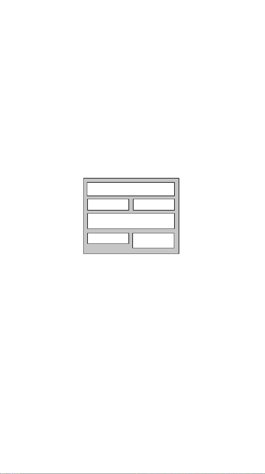
Pentium Pro Processor Architecture
CPU Core
8-KB 2-way
Data Cache
256KB 4-way L2 Cache
APIC
8-KB 4-way
Code Cache
Bus Controller
Figure 1-1 Pentium Pro Processor Architecture
AcerAltos 19000 User’s Guide
1-2
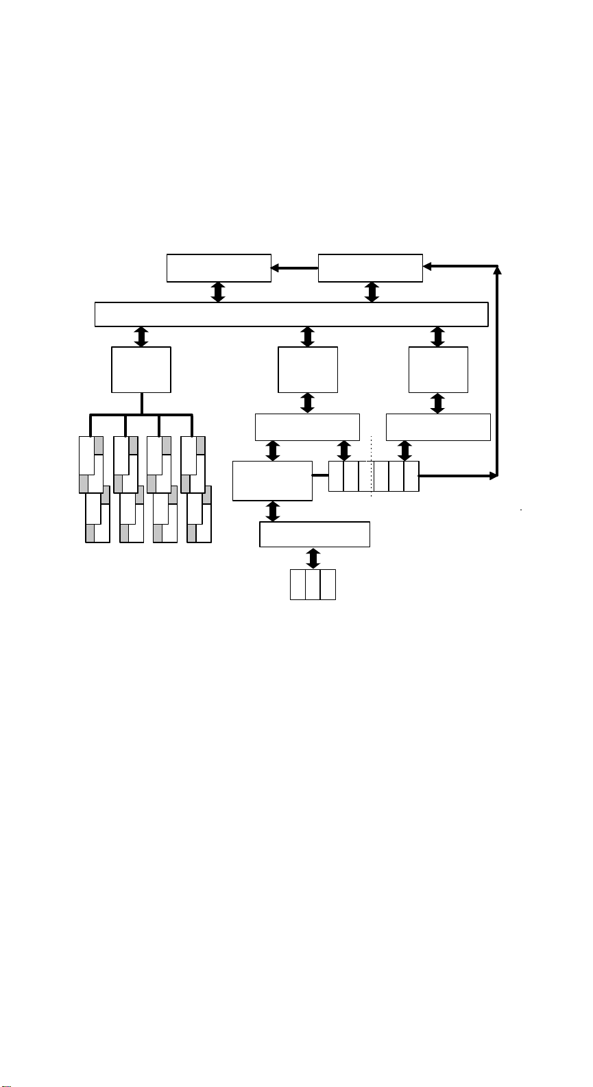
1.1.2 System Architecture
The system bus, PCI buses, EISA bus, PCI bridge (PB), memory controller (MC),
PCI/EISA Bridge (PCEB), and EISA system controller (ESC) comprise the basic
system architecture.
Pentium Pro CPU 1
256 Cache
DC/DP/MIC
3 2 1 0
1
1
1
1
2
2
2
2
1
1
1
1
2
2
2
2
7 6 5 4
4-way Interleave ECC Memory
SIMM * 16
Figure 1-2 System Architecture
Pentium Pro CPU 2
256 Cache
64-bit Pentium Pro MP Bus
PCI Bridge
(PB)
PCI Bus 1 132MB/s PCI Bus 2 132MB/s
1 2 3
1 2 3 4 5 6
PCI Slots
EISA Slots
PCI/EISA Bridge
(PCEB/ESC)
EISA Bus 32MB/s
PCI Bridge
(PB)
APIC Bus
Chapter 1 - System Introduction
1-3

System Bus
The system bus is the CPU’s major connection to all the system devices, primarily
the PCI and EISA bridges, and the memory controller. It can handle as many as
eight outstanding transactions at a time through a transaction pipelining feature,
in which consecutive tasks from the CPU are queued in and transported to the
designated devices on a first-in first-out basis. Pipelining allows for transaction
overlapping in different phases, as the CPU does not have to wait for each to
complete before it issues the next transaction. This produces significant
improvement in overall system performance.
The bus architecture supports a number of features that ensure high reliability. It
has an 8-bit error correction code (ECC) that protects the data lines and a 2-bit
parity code that protects the address lines.
The bus uses Gunning Transceiver Logic (GTL+) and a synchronous latched bus
protocol that simplifies timing constraints. This protocol supports higher
frequency system designs and along with GTL+, requires a low voltage which
reduces electromagnetic interference (EMI) resulting in a lower power
consumption.
PCI and EISA Buses
The system supports two PCI buses created by the two PCI bridge chips (PB).
The PCI buses serve as links between the PCI bridges and PCI devices onboard.
The presence of two buses instead of one reduces I/O bottlenecks and matches
the higher bandwidth of the CPU for faster data transfers.
The EISA bus connects EISA devices to other system devices through the
PCI/EISA bridge (PCEB) and the EISA system controller (ESC). The use of the
PCEB and ESC maintain compatibility within the EISA environment.
AcerAltos 19000 User’s Guide
1-4

PCI Bridge (PB)
The PCI Bridge (PB) is an I/O subsystem solution for high-performance systems.
The PB translates transactions between the system bus and the PCI buses using
32-byte buffers for inbound and outbound posting. The use of two PBs in the
system creates an architecture that allows even faster data transfers.
Memory Controller (MC)
The memory controller (MC) acts as an interface between the system bus and
system memory. It consists of the DRAM control (DC) chip and the data
path (DP) chip. The MC connects to the DRAM array through four memory
interface controller (MIC) chips. The MC supports 256-bit 4-way memory
interleaving resulting in more efficient memory traffic management.
1.1.3 SCSI Subsystem
The AcerAltos 19000 system supports an array of 14 hot-pluggable disk drive
trays through two 7-slot SCSI backplane boards. The trays accommodate wide
SCSI hard disks. With an onboard AIC-7880 SCSI controller, the burst transfer
rate can reach 20 MB per second.
1.1.4 Server Management
Acer Server Manager (ASM) Pro, a server management feature, monitors voltage
and CPU thermal stability, prevents data loss by prompt ECC memory error
reporting, maximizes system resources by indicating PCI bus utilization, and
promotes efficiency by minimizing system downtime. If this feature has been
implemented, refer to the Acer Server Manager (ASM) Pro User’s Guide for
information.
Remote Device Manager (RDM) permits system diagnosis from a remote site
through a modem. RDM facilitates fixing of certain detected problems, changing
system configuration or rebooting in the event of system failure. If this feature
has been implemented, refer to the RDM documentation for information.
Chapter 1 - System Introduction
1-5

1.1.5 Redundant Power Supply Subsystem
The system ships with two load-sharing power supply modules. Load sharing
significantly extends the life of the power supplies. The power subsystem also
supports a redundant configuration such that if one power supply fails, the other
continues to provide system power.
A third power supply module is available as an option. This power supply
module is redundant, but not load-sharing; however, if either the primary or
secondary power supply module fails, the third power supply module load
shares with the remaining power supply module.
An important segment of the power subsystem is the optional battery module.
Providing backup support to the power supply modules, the battery
automatically charges whenever the system is on. This gives a fully-configured
system the ability to run through short interruptions in wall power or to continue
supplying system power for up to eight minutes in the event of total AC power
failure.
1.1.6 Security
The system housing comes with mechanical security locks on both the front panel
and the side panels, preventing unauthorized access to the internal components.
The system BIOS secures the CMOS data and other system software with poweron password, keyboard password, setup control, disk drive control, and monitor
control.
AcerAltos 19000 User’s Guide
1-6
1.2 External Configuration
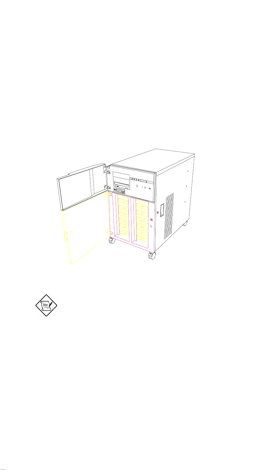
1.2.1 Front Panel
The system front panel is divided into two sections. The upper front panel
consists of the diskette/CD-ROM/tape drive bays, keylock, power switch, LED
indicators, LCD display screen, and an embedded reset switch.
The lower section contains externally accessible hard disk drive bays and drive
trays for wide SCSI drives. The AcerAltos 19000 ships with 7 drive trays in the
left side.
Figure 1-3 Front Panel
The system keys are inside the front panel.
Chapter 1 - System Introduction
1-7
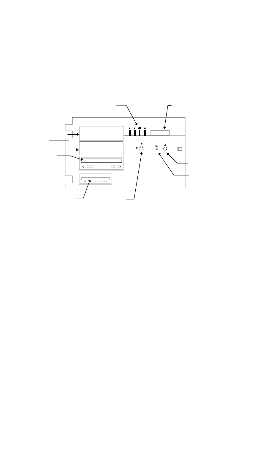
Front Panel Features
Figure 1-4 gives a closer look at the upper front panel features.
5.25-inch
Drive Bays
CD-ROM Drive
3.5-inch
Diskette Drive
LED Indicators
Keylock
LCD Display Screen
Power Switch
Reset Switch
(embedded)
Figure 1-4 Front Panel Features
CD-ROM Drive
The basic system comes with a SCSI CD-ROM drive already installed.
3.5-inch Diskette Drive
A 3.5-inch diskette drive also comes with the basic system.
AcerAltos 19000 User’s Guide
1-8

5.25-inch Drive Bays
Two empty 5.25-inch drive bays allow installation of additional externallyaccessible devices.
Power Switch
The power switch allows you to turn the system power on or off.
Reset Switch
Pressing the reset switch generates a hardware reset pulse that restarts the system
initializing all the registers, buffers, and memory subsystems.
Keylock
The keylock gives security to the system against unauthorized users. Turning the
keylock to the unlocked position enables the power and reset switches. Turning
the keylock to the locked position disables both switches whether the system is on
or off. Supposing the system is on and you intend to reset or turn it off, make
sure that the keylock is unlocked. Otherwise, the switches do not respond.
Chapter 1 - System Introduction
1-9
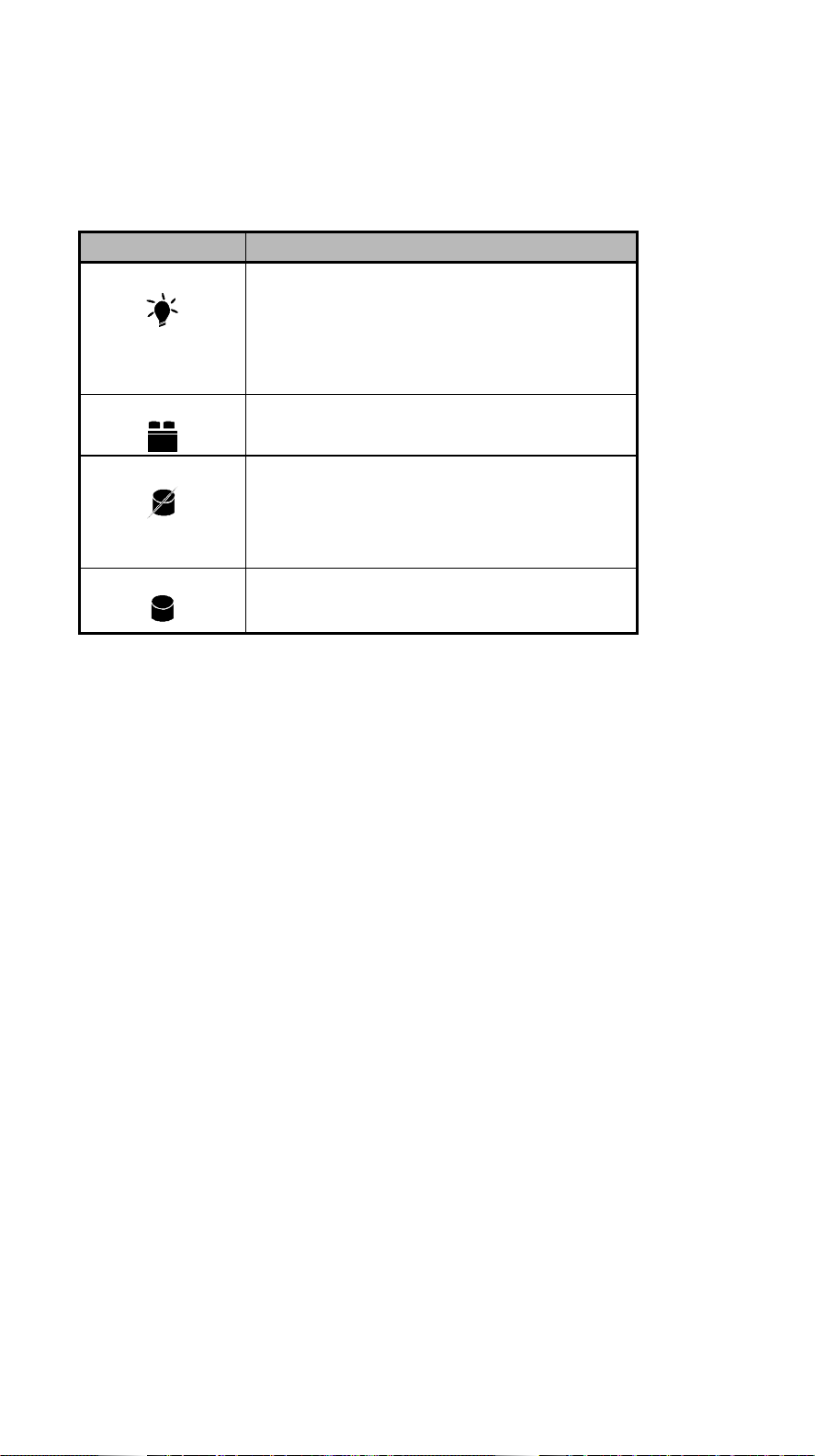
LED Indicators
Table 1-1 LED Indicator Description (Right to Left)
LED Icons Description
Power Status Green Indicates that power is on. All the power
supply modules are in good condition
and the system is running on AC power.
Red Indicates that power is on, but AC has
failed and the system is running on
battery power.
Battery Status
UPS
Hard Disk Failure Green Indicates that all the hard disks installed
Hard Disk Busy Green Indicates that at least one of the hard
Green Indicates that a battery is present.
Red Indicates low battery power.
in the backplane board are in good
condition.
Red Indicates that one of the hard disks
installed in the backplane board is bad.
disks is currently being accessed.
LCD Display Screen
The LCD display is a two-line by 16-character screen that indicates the boot status
as well as any BIOS check point errors encountered upon system initialization.
Normally, the system BIOS and the microcontroller firmware send the LCD
display messages that appear on the screen. However, if you hook up a special
purpose driver to control the LCD module, this driver defines the messages.
AcerAltos 19000 User’s Guide
1-10

Table 1-2 lists the LCD messages from the system BIOS and the microcontroller at
power on.
Table 1-2 LCD Messages
Message Description
Hello! Welcome ! This is the first message that appears on the
LCD screen. This message indicates that the
microcontroller is operational.
POST Checkpoints During system Power-On Self-Test (POST),
the LCD screen shows which POST checkpoint is currently being tested.
Power #1 Fails ! After POST, the microcontroller checks the
power subsystem status. If it detects that
power supply module 1 is bad, it sends this
message to the LCD screen.
Power #2 Fails ! If the microcontroller detects that power
supply module 2 is bad, it sends this
message to the LCD screen.
Power #3 Fails ! If the microcontroller detects that power
supply module 3 is bad, it sends this
message to the LCD screen.
Battery Low ! This message indicates that battery power is
running out. When this message appears,
shutdown the system as soon as possible.
Power Fan Fails ! This message indicates that one or more
fans of the power subsystem failed.
Chapter 1 - System Introduction
1-11
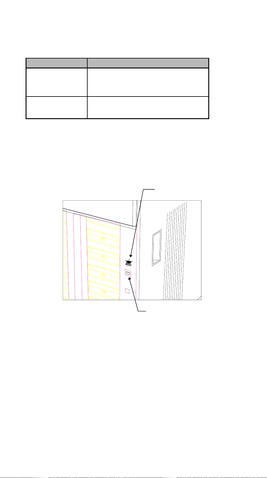
Table 1-2 LCD Messages (continued)
Message Description
AC Power Fails ! When this message appears, it indicates
there is no power coming from the AC line
and the system is currently running on
battery power.*
AcerAltos 19000 This message appears after POST and other
system initialization tests, indicating the
system is up and running.
* An optional UPS provides a reliable power backup in case of a total AC power loss. To
use the UPS feature, you must have Acer Server Manager (ASM) Pro software installed.
RDM Button
The RDM button located on the lower right panel enables Remote Device
Manager (RDM). If this feature has been implemented, refer to the RDM
documentation for information .
RDM Icon
AcerAltos 19000 User’s Guide
1-12
RDM Button
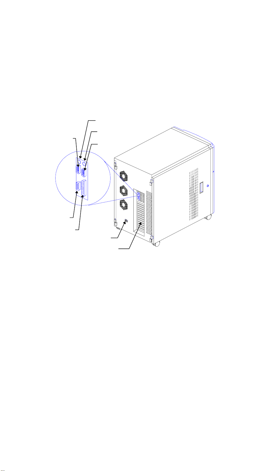
Figure 1-5 RDM Button
1.2.2 Rear Panel
The rear panel includes connectors for the keyboard, mouse, VGA monitor,
printer, and serial devices. Below these connectors are slot openings for
expansion boards. On the lower left is the power cable socket.
Keyboard Port
Mouse Port
Serial Port 2
Video Port
Serial Port 1
Parallel Port
Expansion Slot Bracket
Figure 1-6 Rear Panel
Power Socket
Chapter 1 - System Introduction
1-13

AcerAltos 19000 User’s Guide
1-14
 Loading...