

Page 1

VDSL Switch-VS4512
VDSL Switch-VS4512DC
Management Guide
Page 2

Page 3

Management Guide
VDSL Switch-V4512
VDSL Switch (with AC power connector) supporting 12 VDSL lines, with
2 Slots for Optional 1000BASE-SX, 1000BASE-LX, 1000BASE-T or
1000BASE-X GBIC uplink modules
VDSL Switch-VS4512DC
VDSL Switch (with DC power connector) supporting 12 VDSL lines, with
2 Slots for Optional 1000BASE-SX, 1000BASE-LX, 1000BASE-T or
1000BASE-X GBIC uplink modules
Page 4

Copyright © 2003 by Accton Technology Corporation. All rights reserved.
No part of this document may be copied or reproduced in any form or by any means without the prior written
consent of Accton Technology Corporation.
Accton makes no warranties with respect to this documentation and disclaims any implied warranties of
merchantability, quality, or fitness for any particular purpose. The information in this document is subject to
change without notice. Accton reserves the right to make revisions to this publication without obligation to
notify any person or entity of any such changes.
International Headquarters
No. 1 Creation Road III,
Science-based Industrial Park
Hsinchu 300, Taiwan
Phone: 886-3-5770-270
Fax: 886-3-5770-267
Internet: support@accton.com.tw
Europe Headquarters
Edificio Conata II,
Calle Fructuós Gelabert 6-8, 2
08970 - Sant Joan Despí,
Barcelona, Spain.
Phone: +34-93-477-4920
Fax: +34-93-477-3774
o
, 4a,
Asia Pacific Headquarters
1 Claymore Drive
#08-05/06 Orchard Towers (Rear Block)
Singapore 229594
Phone: +65 238 6556
Fax: +65 238 6466
Internet: www.acctontech.com
Accton is a trademark of Accton Technology Corporation. Other trademarks or brand names mentioned
herein are trademarks or registered trademarks of their respective companies.
VS4512
VS4512DC
F1.0.4.0 E122003-R02
150000041800A
Page 5

Contents
Chapter 1: Introduction 1-1
Key Features 1-1
Description of Software Features 1-2
System Defaults 1-5
Chapter 2: Initial Configuration 2-1
Connecting to the Switch 2-1
Configuration Options 2-1
Required Connections 2-2
Remote Connections 2-3
Basic Configuration 2-3
Console Connection 2-3
Setting Passwords 2-4
Setting an IP Address 2-4
Manual Configuration 2-4
Dynamic Configuration 2-5
Enabling SNMP Management Access 2-6
Community Strings 2-6
Trap Receivers 2-7
Saving Configuration Settings 2-7
Managing System Files 2-8
Chapter 3: Configuring the Switch 3-1
Using the Web Interface 3-1
Navigating the Web Browser Interface 3-2
Home Page 3-2
Configuration Options 3-2
Panel Display 3-3
Main Menu 3-3
Basic Configuration 3-7
Displaying System Information 3-7
Displaying Switch Hardware/Software Versions 3-9
Displaying Bridge Extension Capabilities 3-10
Setting the Switch’s IP Address 3-11
Manual Configuration 3-12
Using DHCP/BOOTP 3-13
Fan Status 3-14
Managing Firmware 3-14
Downloading System Software from a Server 3-15
i
Page 6

Contents
Saving or Restoring Configuration Settings 3-16
Downloading Configuration Settings from a Server 3-16
Setting the Startup Configuration File 3-17
Copying the Running Configuration to a File 3-17
Resetting the System 3-18
Setting the System Clock 3-18
Configuring SNTP 3-18
Setting the Time Zone 3-19
Simple Network Management Protocol 3-20
Setting Community Access Strings 3-21
Specifying Trap Managers and Trap Types 3-22
Filtering Addresses for SNMP Client Access 3-23
User Authentication. 3-24
Configuring the Logon Password 3-24
Configuring Local/Remote Logon Authentication 3-25
Telnet Settings 3-28
Configuring HTTPS 3-28
Replacing the Default Secure-site Certificate 3-29
Configuring the Secure Shell 3-30
Configuring Port Security 3-31
Configuring 802.1x Port Authentication 3-33
Displaying 802.1x Global Settings 3-34
Configuring 802.1x Global Settings 3-36
Configuring Port Authorization Mode 3-37
Displaying 802.1x Statistics 3-38
Port Configuration 3-39
Displaying Connection Status 3-39
Configuring Interface Connections 3-42
Creating Trunk Groups 3-44
Statically Configuring a Trunk 3-45
Enabling LACP on Selected Ports 3-46
Setting Broadcast Storm Thresholds 3-48
Configuring Port Mirroring 3-49
Configuring Rate Limits 3-50
Showing Port Statistics 3-51
VDSL Configuration 3-56
VDSL Global Configuration 3-56
VDSL Port Configuration 3-58
VDSL Port Link Status 3-61
Displaying VDSL Port Ethernet Statistics 3-64
VDSL Line Configuration 3-65
Displaying VDSL Interface Information 3-66
VDSL Performance Monitor Information 3-69
Monitoring VDSL Performance History 3-72
ii
Page 7

Contents
Address Table Settings 3-73
Setting Static Addresses 3-73
Displaying the Address Table 3-74
Changing the Aging Time 3-75
Spanning Tree Algorithm Configuration 3-76
Displaying Global Settings 3-77
Configuring Global Settings 3-79
Displaying Interface Settings 3-81
Configuring Interface Settings 3-84
VLAN Configuration 3-86
Overview 3-86
Assigning Ports to VLANs 3-87
Forwarding Tagged/Untagged Frames 3-88
Displaying Basic VLAN Information 3-88
Displaying Current VLANs 3-89
Creating VLANs 3-91
Adding Static Members to VLANs (VLAN Index) 3-92
Adding Static Members to VLANs (Port Index) 3-93
Configuring VLAN Behavior for Interfaces 3-94
Configuring Private VLANs 3-96
Enabling Private VLANs 3-97
Configuring Uplink and Downlink Ports 3-97
Class of Service Configuration 3-98
Setting the Default Priority for Interfaces 3-98
Mapping CoS Values to Egress Queues 3-100
Selecting the Queue Mode 3-101
Setting the Service Weight for Traffic Classes 3-102
Mapping Layer 3/4 Priorities to CoS Values 3-103
Selecting IP Precedence/DSCP Priority 3-103
Mapping IP Precedence 3-104
Mapping DSCP Priority 3-105
Mapping IP Port Priority 3-107
Copy Priority Settings 3-108
Multicast Filtering 3-109
Layer 2 IGMP (Snooping and Query) 3-109
Configuring IGMP Snooping and Query Parameters 3-110
Displaying Interfaces Attached to a Multicast Router 3-111
Specifying Static Interfaces for a Multicast Router 3-112
Displaying Port Members of Multicast Services 3-113
Assigning Ports to Multicast Services 3-114
iii
Page 8

Contents
Chapter 4: Command Line Interface 4-1
Using the Command Line Interface 4-1
Accessing the CLI 4-1
Console Connection 4-1
Telnet Connection 4-1
Entering Commands 4-3
Keywords and Arguments 4-3
Minimum Abbreviation 4-3
Command Completion 4-3
Getting Help on Commands 4-3
Showing Commands 4-4
Partial Keyword Lookup 4-4
Negating the Effect of Commands 4-5
Using Command History 4-5
Understanding Command Modes 4-5
Exec Commands 4-5
Configuration Commands 4-6
Command Line Processing 4-7
Command Groups 4-8
Line Commands 4-9
line 4-9
login 4-10
password 4-11
exec-timeout 4-12
password-thresh 4-12
silent-time 4-13
databits 4-14
parity 4-14
speed 4-15
stopbits 4-16
disconnect 4-16
show line 4-17
General Commands 4-17
enable 4-18
disable 4-18
configure 4-19
show history 4-19
reload 4-20
end 4-21
exit 4-21
quit 4-21
System Management Commands 4-22
Device Designation Commands 4-22
prompt 4-23
hostname 4-23
iv
Page 9

Contents
User Access Commands 4-24
username 4-24
enable password 4-25
IP Filter Commands 4-26
management 4-26
show management 4-27
Web Server Commands 4-28
ip http port 4-28
ip http server 4-28
ip http secure-server 4-29
ip http secure-port 4-30
ip telnet server 4-30
Secure Shell Commands 4-31
ip ssh server 4-31
ip ssh timeout 4-32
ip ssh authentication-retries 4-33
disconnect ssh 4-33
show ip ssh 4-34
show ssh 4-34
Event Logging Commands 4-35
logging on 4-35
logging history 4-36
logging host 4-37
logging facility 4-37
logging trap 4-38
clear logging 4-38
show logging 4-39
SMTP Alert Commands 4-40
logging sendmail host 4-41
logging sendmail level 4-41
logging sendmail source-email 4-42
logging sendmail destination-email 4-42
logging sendmail 4-43
show logging sendmail 4-43
Time Commands 4-44
sntp client 4-44
sntp server 4-45
sntp poll 4-46
sntp broadcast client 4-47
show sntp 4-47
clock timezone 4-48
calendar set 4-48
show calendar 4-49
v
Page 10

Contents
System Status Commands 4-49
show startup-config 4-49
show running-config 4-51
show system 4-53
show users 4-53
show version 4-54
Flash/File Commands 4-55
copy 4-55
delete 4-57
dir 4-58
whichboot 4-59
boot system 4-59
Authentication Commands 4-60
Authentication Sequence 4-60
authentication login 4-60
RADIUS Client 4-61
radius-server host 4-61
radius-server port 4-62
radius-server key 4-62
radius-server retransmit 4-63
radius-server timeout 4-63
show radius-server 4-64
TACACS+ Client 4-64
tacacs-server host 4-64
tacacs-server port 4-65
tacacs-server key 4-65
show tacacs-server 4-66
Port Security Commands 4-66
port security 4-67
802.1x Port Authentication 4-68
authentication dot1x default 4-68
dot1x default 4-69
dot1x max-req 4-69
dot1x port-control 4-70
dot1x operation-mode 4-70
dot1x re-authenticate 4-71
dot1x re-authentication 4-71
dot1x timeout quiet-period 4-71
dot1x timeout re-authperiod 4-72
dot1x timeout tx-period 4-72
show dot1x 4-73
vi
Page 11

Contents
SNMP Commands 4-76
snmp-server community 4-76
snmp-server contact 4-77
snmp-server location 4-77
snmp-server host 4-78
snmp-server enable traps 4-79
snmp ip filter 4-80
show snmp 4-81
DHCP Commands 4-82
DHCP Client 4-82
ip dhcp client-identifier 4-82
ip dhcp restart client 4-83
Interface Commands 4-84
interface 4-84
description 4-85
speed-duplex 4-85
negotiation 4-86
capabilities 4-87
flowcontrol 4-88
shutdown 4-89
switchport broadcast packet-rate 4-89
clear counters 4-90
show interfaces status 4-91
show interfaces counters 4-92
show interfaces switchport 4-93
Mirror Port Commands 4-95
port monitor 4-95
show port monitor 4-96
Rate Limit Commands 4-97
rate-limit 4-97
Link Aggregation Commands 4-98
channel-group 4-99
lacp 4-99
VDSL Commands 4-101
efm profile global 4-102
efm profile 4-103
efm reset 4-104
efm shutdown 4-104
efm rdl 4-105
efm interleave 4-106
efm noise-margin 4-107
efm rate-adapt 4-108
efm pbo 4-109
show controllers ethernet-controller 4-109
show controllers efm actual 4-111
vii
Page 12

Contents
show controllers efm admin 4-112
show controllers efm profile 4-112
show controllers efm status 4-114
show controllers efm remote ethernet mode 4-115
show controllers efm-noise-margin 4-116
show controllers efm channel-performance 4-117
show controllers efm line-table 4-117
show controllers efm phy-table 4-118
show controllers efm channel-table 4-119
show controllers efm current-performance 4-120
Address Table Commands 4-122
mac-address-table static 4-122
clear mac-address-table dynamic 4-123
show mac-address-table 4-123
mac-address-table aging-time 4-124
show mac-address-table aging-time 4-125
Spanning Tree Commands 4-125
spanning-tree 4-126
spanning-tree mode 4-126
spanning-tree forward-time 4-127
spanning-tree hello-time 4-128
spanning-tree max-age 4-128
spanning-tree priority 4-129
spanning-tree pathcost method 4-130
spanning-tree transmission-limit 4-130
spanning-tree cost 4-131
spanning-tree port-priority 4-132
spanning-tree edge-port 4-132
spanning-tree portfast 4-133
spanning-tree link-type 4-134
spanning-tree protocol-migration 4-135
show spanning-tree 4-135
VLAN Commands 4-137
Editing VLAN Groups 4-137
vlan database 4-137
vlan 4-138
Configuring VLAN Interfaces 4-139
interface vlan 4-139
switchport mode 4-140
switchport acceptable-frame-types 4-140
switchport ingress-filtering 4-141
switchport native vlan 4-142
switchport allowed vlan 4-142
Displaying VLAN Information 4-143
show vlan 4-143
viii
Page 13

Contents
Configuring Private VLANs 4-144
pvlan 4-144
show pvlan 4-145
Bridge Extension Commands 4-146
show bridge-ext 4-146
Priority Commands 4-147
Priority Commands (Layer 2) 4-147
switchport priority default 4-147
queue mode 4-148
queue bandwidth 4-149
queue cos-map 4-150
show queue mode 4-151
show queue bandwidth 4-151
show queue cos-map 4-151
Priority Commands (Layer 3 and 4) 4-152
map ip precedence (Global Configuration) 4-152
map ip precedence (Interface Configuration) 4-153
map ip dscp (Global Configuration) 4-153
map ip dscp (Interface Configuration) 4-154
map ip port (Global Configuration) 4-155
map ip port (Interface Configuration) 4-155
show map ip precedence 4-156
show map ip dscp 4-156
show map ip port 4-157
Multicast Filtering Commands 4-158
IGMP Snooping Commands 4-158
ip igmp snooping 4-158
ip igmp snooping vlan static 4-159
ip igmp snooping version 4-159
show ip igmp snooping 4-160
show mac-address-table multicast 4-161
IGMP Query Commands (Layer 2) 4-161
ip igmp snooping querier 4-162
ip igmp snooping query-count 4-162
ip igmp snooping query-interval 4-163
ip igmp snooping query-max-response-time 4-163
ip igmp snooping router-port-expire-time 4-164
Static Multicast Routing Commands 4-165
ip igmp snooping vlan mrouter 4-165
show ip igmp snooping mrouter 4-166
ix
Page 14

Contents
IP Interface Commands 4-166
Basic IP Configuration 4-166
ip address 4-167
ip default-gateway 4-168
show ip interface 4-168
show ip redirects 4-169
ping 4-169
Appendix A: Software Specifications A-1
Software Features A-1
Management Features A-2
Standards A-2
Management Information Bases A-3
Appendix B: Troubleshooting C-1
Glossary
Index
x
Page 15

Chapter 1: Introduction
The switch provides a broad range of features for Layer 2 switching. It includes a
management agent that allows you to configure the features listed in this manual.
The default configuration can be used for most of the features provided by this
switch. However, there are many options that you should configure to maximize the
switch’s performance for your particular network environment.
The switch uses four frequency bands (two downstream and two upstream) for
VDSL lines. These frequency bands conform to ANSI Plan 998. Details of the
frequency bands are given in the table below.
Key Features
Feature Description
4-Band VDSL Total Bandwidth: 11.1 MHz
Bandwidth Allocation: Downstream 1 (0.9-3.75 MHz),
Downstream 2 (5.2-8.5 MHz), Upstream 1 (3.75-5.2 MHz),
Upstream 2 (8.5-12 MHz)
Configuration Backup
and Restore
Authentication Console, Telnet, web – User name / password, RADIUS,
DHCP Client Supported
Port Configuration Speed, duplex mode and flow control
Rate Limiting Input and output rate limiting per port
Port Mirroring One or more ports mirrored to single analysis port
Port Trunking Supports 1 Gigabit trunk using either static or dynamic trunking
Broadcast Storm
Control
Static Address Up to 8K MAC addresses in the forwarding table
IEEE 802.1D Bridge Supports dynamic data switching and addresses learning
Store-and-Forward
Switching
Spanning Tree
Protocol
Backup to TFTP server
TACACS+
Web – HTTPS; Telnet – SSH
SNMP – Community strings, IP address filtering
Port – IEEE 802.1x, MAC address filtering
(LACP)
Supported
Supported to ensure wire-speed switching while eliminating bad
frames
Supports standard STP and Rapid Spanning Tree Protocol
(RSTP)
1-1
Page 16

Introduction
Feature Description
Virtual LANs Up to 255 using IEEE 802.1Q, port-based, or private VLANs
Traffic Prioritization Default port priority, traffic class map, queue scheduling,
Multicast Filtering Supports IGMP snooping and query
IP Precedence, or Differentiated Services Code Point (DSCP)
Description of Software Features
The switch provides a wide range of advanced performance enhancing features.
Flow control eliminates the loss of packets due to bottlenecks caused by port
saturation. Broadcast storm suppression prevents broadcast traffic storms from
engulfing the network. Port-based VLANs provide traffic security and efficient use of
network bandwidth. CoS priority queueing ensures the minimum delay for moving
real-time multimedia data across the network. While multicast filtering provides
support for real-time network applications. Some of the management features are
briefly described below.
Configuration Backup and Restore – You can save the current configuration
settings to a file on a TFTP server, and later download this file to restore the switch
configuration settings.
Authentication – This switch authenticates management access via the console
port, Telnet or web browser. User names and passwords can be configured locally or
can be verified via a remote authentication server (i.e., RADIUS or TACACS+).
Port-based authentication is also supported via the IEEE 802.1x protocol. This
protocol uses the Extensible Authentication Protocol over LANs (EAPOL) to request
user credentials from the 802.1x client, and then verifies the client’s right to access
the network via an authentication server.
Other authentication options include HTTPS for secure management access via the
web, SSH for secure management access over a Telnet-equivalent connection,
IP address filtering for SNMP/web/Telnet management access, and MAC address
filtering for port access.
Port Configuration – You can manually configure the speed, duplex mode, and
flow control used on specific ports, or use auto-negotiation to detect the connection
settings used by the attached device. Use the full-duplex mode on ports whenever
possible to double the throughput of switch connections. Flow control should also be
enabled to control network traffic during periods of congestion and prevent the loss
of packets when port buffer thresholds are exceeded. The switch supports flow
control based on the IEEE 802.3x standard.
Rate Limiting – This feature controls the maximum rate for traffic transmitted or
received on an interface. Rate limiting is configured on interfaces at the edge of a
network to limit traffic into or out of the network. Traffic that falls within the rate limit is
transmitted, while packets that exceed the acceptable amount of traffic are dropped.
1-2
Page 17

Description of Software Features
Port Mirroring – The switch can unobtrusively mirror traffic from any port to a
monitor port. You can then attach a protocol analyzer or RMON probe to this port to
perform traffic analysis and verify connection integrity.
Port Trunking – Ports can be combined into an aggregate connection. Trunks can
be manually set up or dynamically configured using IEEE 802.3ad Link Aggregation
Control Protocol (LACP). The additional ports dramatically increase the throughput
across any connection, and provide redundancy by taking over the load if a port in
the trunk should fail. The switch supports one trunk with two Gigabit optional module
ports.
Broadcast Storm Control – Broadcast suppression prevents broadcast traffic from
overwhelming the network. When enabled on a port, the level of broadcast traffic
passing through the port is restricted. If broadcast traffic rises above a pre-defined
threshold, it will be throttled until the level falls back beneath the threshold.
Static Addresses – A static address can be assigned to a specific interface on this
switch. Static addresses are bound to the assigned interface and will not be moved.
When a static address is seen on another interface, the address will be ignored and
will not be written to the address table. Static addresses can be used to provide
network security by restricting access for a known host to a specific port.
IEEE 802.1D Bridge – The switch supports IEEE 802.1D transparent bridging. The
address table facilitates data switching by learning addresses, and then filtering or
forwarding traffic based on this information. The address table supports up to 8K
addresses.
Store-and-Forward Switching – The switch copies each frame into its memory
before forwarding them to another port. This ensures that all frames are a standard
Ethernet size and have been verified for accuracy with the cyclic redundancy check
(CRC). This prevents bad frames from entering the network and wasting bandwidth.
To avoid dropping frames on congested ports, the switch provides 8 MB for frame
buffering. This buffer can queue packets awaiting transmission on congested
networks.
Spanning Tree Protocol – The switch supports these spanning tree protocols:
Spanning Tree Protocol (STP, IEEE 802.1D) – This protocol adds a level of fault
tolerance by allowing two or more redundant connections to be created between a
pair of LAN segments. When there are multiple physical paths between segments,
this protocol will choose a single path and disable all others to ensure that only one
route exists between any two stations on the network. This prevents the creation of
network loops. However, if the chosen path should fail for any reason, an alternate
path will be activated to maintain the connection.
Rapid Spanning Tree Protocol (RSTP, IEEE 802.1w) – This protocol reduces the
convergence time for network topology changes to about 10% of that required by the
older IEEE 802.1D STP standard. It is intended as a complete replacement for STP,
but can still interoperate with switches running the older standard by automatically
reconfiguring ports to STP-compliant mode if they detect STP protocol messages
from attached devices.
1-3
Page 18

Introduction
Virtual LANs – The switch supports up to 255 VLANs. A Virtual LAN is a collection
of network nodes that share the same collision domain regardless of their physical
location or connection point in the network. The switch supports tagged VLANs
based on the IEEE 802.1Q standard. Members of VLAN groups can be manually
assigned to a specific set of VLANs. This allows the switch to restrict traffic to the
VLAN groups to which a user has been assigned. By segmenting your network into
VLANs, you can:
• Eliminate broadcast storms which severely degrade performance in a flat network.
• Simplify network management for node changes/moves by remotely configuring
VLAN membership for any port, rather than having to manually change the network
connection.
• Provide data security by restricting all traffic to the originating VLAN.
• Use private VLANs to restrict traffic to pass only between data ports and the uplink
ports, thereby isolating adjacent ports within the same VLAN, and allowing you to
limit the total number of VLANs that need to be configured.
Traffic Prioritization – This switch prioritizes each packet based on the required
level of service, using four priority queues with strict or Weighted Round Robin
Queuing. It uses IEEE 802.1p and 802.1Q tags to prioritize incoming traffic based on
input from the end-station application. These functions can
independent priorities for delay-sensitive data and best-effort data.
This switch also supports several common methods of prioritizing layer 3/4 traffic to
meet application requirements. Traffic can be prioritized based on the priority bits in
the IP frame’s Type of Service (ToS) octet. When these services are enabled, the
priorities are mapped to a Class of Service value by the switch, and the traffic then
sent to the corresponding output queue.
Multicast Filtering – Specific multicast traffic can be assigned to its own VLAN to
ensure that it does not interfere with normal network traffic and to guarantee
real-time delivery by setting the required priority level for the designated VLAN. The
switch uses IGMP Snooping and Query to manage multicast group registration.
be used to provide
1-4
Page 19

System Defaults
System Defaults
The switch’s system defaults are provided in the configuration file
“Factory_Default_Config.cfg.” To reset the switch defaults, this file should be set as
the startup configuration file (page 3-17).
The following table lists some of the basic system defaults.
Function Parameter Default
IP Settings Management VLAN 1
DHCP Enabled
BOOTP Disabled
User Specified Disabled
IP Address 0.0.0.0
Subnet Mask 255.0.0.0
Default Gateway 0.0.0.0
Console Port
Connection
Authentication Privileged Exec Level Username “admin”
Baud Rate 9600
Data bits 8
Stop bits 1
Parity none
Local Console Timeout 0 (disabled)
Password “admin”
Normal Exec Level Username “guest”
Enable Privileged Exec from
Normal Exec Level
RADIUS Authentication Disabled
TACACS Authentication Disabled
802.1x Port Authentication Disabled
SSL Enabled
HTTPS Enabled
SSH version 2.0 Enabled
Port Security Disabled
Password “guest”
Password “super”
1-5
Page 20

Introduction
Function Parameter Default
Web Management HTTP Server Enabled
HTTP Port Number 80
HTTP Secure Server Enabled
HTTP Secure Port Number 443
SNMP Community Strings “public” (read only)
Traps Authentication traps: enabled
IP Filtering Disabled
Port Configuration Admin Status Enabled
Auto-negotiation Enabled
Flow Control Disabled
Port Capability 100BASE-TX –
Module Port Capability 1000BASE-T/SX/LX/LH –
Rate Limiting Input and output limits Disabled
Port Trunking Static Trunks None
LACP (all ports) Disabled
Broadcast Storm
Protection
Spanning Tree
Protocol
Address Table Aging Time 300 seconds
Virtual LANs Default VLAN 1
Status Enabled (all ports)
Broadcast Limit Rate 500 packets per second
Status Enabled
Fast Forwarding (Edge Port) Disabled
PVID 1
“private” (read/write)
Link-up-down events: enabled
10 Mbps half duplex
10 Mbps full duplex
100 Mbps half duplex
100 Mbps full duplex
Full-duplex flow control disabled
Symmetric flow control disabled
1000 Mbps full duplex
Full-duplex flow control disabled
Symmetric flow control disabled
(Defaults: All values based on
IEEE 802.1w)
1-6
Page 21

Function Parameter Default
Acceptable Frame Type All
Ingress Filtering Disabled
Switchport Mode (Egress
Mode)
Traffic Prioritization Ingress Port Priority 0
Weighted Round Robin Queue: 0:1
IP Precedence Priority Disabled
IP DSCP Priority Disabled
IP Settings IP Address 0.0.0.0
Subnet Mask 255.0.0.0
Default Gateway 0.0.0.0
DHCP Client: Disabled
BOOTP Disabled
DNS Server Lookup Disabled
Multicast Filtering IGMP Snooping Snooping: Enabled
System Log Status Enabled
Messages Logged Levels 0-7 (all)
Messages Logged to Flash Levels 0-3
SMTP Email Alerts Event Handler Disabled
SNTP Clock Synchronization Disabled
Hybrid: tagged/untagged frames
1:4
2:16
3:64
Querier: Enabled
System Defaults
1-7
Page 22

Introduction
1-8
Page 23

Chapter 2: Initial Configuration
Connecting to the Switch
Configuration Options
The switch includes a built-in network management agent. The agent offers a variety
of management options, including SNMP, RMON and a Web-based interface. A PC
may also be connected directly to the switch for configuration and monitoring via a
command line interface (CLI).
Note: The IP address for this switch is assigned by DHCP by default. To change this
address, see “Setting an IP Address” on page 2-4.
The switch’s HTTP Web agent allows you to configure switch parameters, monitor
port connections, and display statistics using a standard Web browser such as
Netscape Navigator version 6.2 and higher or Microsoft IE version 5.0 and higher.
The switch’s Web management interface can be accessed from any computer
attached to the network.
The CLI program can be accessed by a direct connection to the RS-232 serial
console port on the switch, or remotely by a Telnet connection over the network.
The switch’s management agent also supports SNMP (Simple Network
Management Protocol). This SNMP agent permits the switch to be managed from
any system in the network using network management software such as
HP OpenView.
The switch’s Web interface, CLI configuration program, and SNMP agent allow you
to perform the following management functions:
• Set user names and passwords for up to 16 users
• Set an IP interface for a management VLAN
• Configure SNMP parameters
• Enable/disable any port
• Set the speed/duplex mode for any port
• Configure the bandwidth of any port by limiting input or output rates
• Configure up to 255 IEEE 802.1Q VLANs
• Configure IGMP multicast filtering
• Upload and download system firmware via TFTP
• Upload and download switch configuration files via TFTP
• Configure Spanning Tree parameters
• Configure Class of Service (CoS) priority queuing
• Configure one trunk with two Gigabit optional module ports
• Enable port mirroring
2-1
Page 24

Initial Configuration
• Globally set broadcast storm control
• Display system information and statistics
Required Connections
The switch provides an RS-232 serial port that enables a connection to a PC or
terminal for monitoring and configuring the switch. A null-modem console cable is
provided with the switch.
Attach a VT100-compatible terminal, or a PC running a terminal emulation program
to the switch. You can use the console cable provided with this package, or use a
null-modem cable that complies with the wiring assignments shown in the
Installation Guide.
To connect a terminal to the console port, complete the following steps:
1. Connect the console cable to the serial port on a terminal, or a PC running
terminal emulation software, and tighten the captive retaining screws on the
DB-9 connector.
2. Connect the other end of the cable to the RS-232 serial port on the switch.
3. Make sure the terminal emulation software is set as follows:
• Select the appropriate serial port (COM port 1 or COM port 2).
• Set to any of the following baud rates: 9600, 19200, 38400, 57600, 115200
(Note: Set to 9600 baud if want to view all the system initialization messages.)
• Set the data format to 8 data bits, 1 stop bit, and no parity.
• Set flow control to none.
• Set the emulation mode to VT100.
• When using HyperTerminal, select Terminal keys, not Windows keys.
Notes: 1. When using HyperTerminal with Microsoft® Windows® 2000, make sure that
you have Windows 2000 Service Pack 2 or later installed. Windows 2000
Service Pack 2 fixes the problem of arrow keys not functioning in
HyperTerminal’s VT100 emulation. See www.microsoft.com for information
on Windows 2000 service packs.
2. Refer to “Line Commands” on page 4-9 for a complete description of console
configuration options.
3. Once you have set up the terminal correctly, the console login screen will be
displayed.
For a description of how to use the CLI, see “Using the Command Line Interface” on
page 4-1. For a list of all the CLI commands and detailed information on using the
CLI, refer to “Command Groups” on page 4-8.
2-2
Page 25

Basic Configuration
Remote Connections
Prior to accessing the switch’s onboard agent via a network connection, you must
first configure it with a valid IP address, subnet mask, and default gateway using a
console connection, DHCP or BOOTP protocol.
The IP address for this switch is assigned by DHCP by default. To manually
configure this address or enable dynamic address assignment via DHCP or BOOTP,
see “Setting an IP Address” on page 2-4.
Note: This switch supports four concurrent Telnet sessions.
After configuring the switch’s IP parameters, you can access the onboard
configuration program from anywhere within the attached network. The onboard
configuration program can be accessed using Telnet from any computer attached to
the network. The switch can also be managed by any computer using a web
browser (Internet Explorer 5.0 or above, or Netscape Navigator 6.2 or above), or
from a network computer using SNMP network management software.
Note: The onboard program only provides access to basic configuration functions. To
access the full range of SNMP management functions, you must use
SNMP-based network management software.
Basic Configuration
Console Connection
The CLI program provides two different command levels — normal access level
(Normal Exec) and privileged access level (Privileged Exec). The commands
available at the Normal Exec level are a limited subset of those available at the
Privileged Exec level and allow you to only display information and use basic
utilities. To fully configure the switch parameters, you must access the CLI at the
Privileged Exec level.
Access to both CLI levels are controlled by user names and passwords. The switch
has a default user name and password for each level. To log into the CLI at the
Privileged Exec level using the default user name and password, perform these
steps:
1. To initiate your console connection, press <Enter>. The “User Access
Verification” procedure starts.
2. At the Username prompt, enter “admin.”
3. At the Password prompt, also enter “admin.” (The password characters are not
displayed on the console screen.)
4. The session is opened and the CLI displays the “Console#” prompt indicating
you have access at the Privileged Exec level.
2-3
Page 26

Initial Configuration
Setting Passwords
Note: If this is your first time to log into the CLI program, you should define new
passwords for both default user names using the “username” command, record
them and put them in a safe place.
Passwords can consist of up to 8 alphanumeric characters and are case sensitive.
To prevent unauthorized access to the switch, set the passwords as follows:
1. Open the console interface with the default user name and password “admin” to
access the Privileged Exec level.
2. Type “configure” and press <Enter>.
3. Type “username guest password 0 password,” for the Normal Exec level, where
password is your new password. Press <Enter>.
4. Type “username admin password 0 password,” for the Privileged Exec level,
where password is your new password. Press <Enter>.
Username: admin
Password:
CLI session with the VDSL 4Band Switch is opened.
To end the CLI session, enter [Exit].
Console#configure
Console(config)#username guest password 0 [password]
Console(config)#username admin password 0 [password]
Console(config)#
Setting an IP Address
You must establish IP address information for the switch to obtain management
access through the network. This can be done in either of the following ways:
Manual — You have to input the information, including IP address and subnet mask.
If your management station is not in the same IP subnet as the switch, you will also
need to specify the default gateway router.
Dynamic — The switch sends IP configuration requests to BOOTP or DHCP
address allocation servers on the network.
Manual Configuration
You can manually assign an IP address to the switch. You may also need to specify
a default gateway that resides between this device and management stations that
exist on another network segment. Valid IP addresses consist of four decimal
numbers, 0 to 255, separated by periods. Anything outside this format will not be
accepted by the CLI program.
Note: The IP address for this switch is assigned by DHCP by default.
2-4
Page 27

Basic Configuration
Before you can assign an IP address to the switch, you must obtain the following
information from your network administrator:
• IP address for the switch
• Default gateway for the network
• Network mask for this network
To assign an IP address to the switch, complete the following steps:
1. From the Privileged Exec level global configuration mode prompt, type
“interface vlan 1” to access the interface-configuration mode. Press <Enter>.
2. Type “ip address ip-address netmask,” where “ip-address” is the switch IP
address and “netmask” is the network mask for the network. Press <Enter>.
3. Type “exit” to return to the global configuration mode prompt. Press <Enter>.
4. To set the IP address of the default gateway for the network to which the switch
belongs, type “ip default-gateway gateway,” where “gateway” is the IP address
of the default gateway. Press <Enter>.
Console(config)#interface vlan 1
Console(config-if)#ip address 192.168.1.5 255.255.255.0
Console(config-if)#exit
Console(config)#ip default-gateway 192.168.1.254
Console(config)#
Dynamic Configuration
If you select the “bootp” or “dhcp” option, IP will be enabled but will not function until
a BOOTP or DHCP reply has been received. You therefore need to use the “ip dhcp
restart client” command to start broadcasting service requests. Requests will be sent
periodically in an effort to obtain IP configuration information. (BOOTP and DHCP
values can include the IP address, subnet mask, and default gateway.)
If the “bootp” or “dhcp” option is saved to the startup-config file (step 6), then the
switch will start broadcasting service requests as soon as it is powered on.
To automatically configure the switch by communicating with BOOTP or DHCP
address allocation servers on the network, complete the following steps:
1. From the Global Configuration mode prompt, type “interface vlan 1” to access
the interface-configuration mode. Press <Enter>.
2. At the interface-configuration mode prompt, use one of the following commands:
• To obtain IP settings via DHCP, type “ip address dhcp” and press <Enter>.
• To obtain IP settings via BOOTP, type “ip address bootp” and press <Enter>.
3. Type “end” to return to the Privileged Exec mode. Press <Enter>.
4. Type “ip dhcp restart client” to begin broadcasting service requests.
Press <Enter>.
2-5
Page 28

Initial Configuration
5. Wait a few minutes, and then check the IP configuration settings by typing the
“show ip interface” command. Press <Enter>.
6. Then save your configuration changes by typing “copy running-config
startup-config.” Enter the startup file name and press <Enter>.
Console(config)#interface vlan 1
Console(config-if)#ip address dhcp
Console(config-if)#end
Console#ip dhcp restart client
Console#show ip interface
IP address and netmask: 192.168.1.54 255.255.255.0 on VLAN 1,
and address mode: User specified.
Console#copy running-config startup-config
Startup configuration file name []: startup
\Write to FLASH Programming.
\Write to FLASH finish.
Success.
Enabling SNMP Management Access
The switch can be configured to accept management commands from Simple
Network Management Protocol (SNMP) applications such as HP OpenView. You
can configure the switch to (1) respond to SNMP requests or (2) generate SNMP
traps.
When SNMP management stations send requests to the switch (either to return
information or to set a parameter), the switch provides the requested data or sets the
specified parameter. The switch can also be configured to send information to
SNMP managers (without being requested by the managers) through trap
messages, which inform the manager that certain events have occurred.
Community Strings
Community strings are used to control management access to SNMP stations, as
well as to authorize SNMP stations to receive trap messages from the switch. You
therefore need to assign community strings to specified users or user groups, and
set the access level.
The default strings are:
• public - with read-only access. Authorized management stations are only able to
retrieve MIB objects.
• private - with read-write access. Authorized management stations are able to both
retrieve and modify MIB objects.
Note: If you do not intend to utilize SNMP, we recommend that you delete both of the
default community strings. If there are no community strings, then SNMP
management access to the switch is disabled.
To prevent unauthorized access to the switch via SNMP, it is recommended that you
change the default community strings.
2-6
Page 29

Basic Configuration
To configure a community string, complete the following steps:
1. From the Privileged Exec level global configuration mode prompt, type
“snmp-server community string mode,” where “string” is the community access
string and “mode” is rw (read/write) or ro (read only). Press <Enter>. (Note that
the default mode is read only.)
2. To remove an existing string, simply type “no snmp-server community string,”
where “string” is the community access string to remove. Press <Enter>.
Console(config)#snmp-server community admin rw
Console(config)#snmp-server community private
Console(config)#
Trap Receivers
You can also specify SNMP stations that are to receive traps from the switch.
To configure a trap receiver, complete the following steps:
1. From the Privileged Exec level global configuration mode prompt, type
“snmp-server host host-address community-string,” where “host-address” is the
IP address for the trap receiver and “community-string” is the string associated
with that host. Press <Enter>.
2. In order to configure the switch to send SNMP notifications, you must enter at
least one snmp-server enable traps command. Type “snmp-server enable traps
type,” where “type” is either authentication or link-up-down. Press <Enter>.
Console(config)#snmp-server enable traps link-up-down
Console(config)#
Saving Configuration Settings
Configuration commands only modify the running configuration file and are not
saved when the switch is rebooted. To save all your configuration changes in
nonvolatile storage, you must copy the running configuration file to the start-up
configuration file using the “copy” command.
To save the current configuration settings, enter the following command:
1. From the Privileged Exec mode prompt, type “copy running-config
startup-config” and press <Enter>.
2. Enter the name of the start-up file. Press <Enter>.
Console#copy running-config startup-config
Startup configuration file name []: startup
\Write to FLASH Programming.
\Write to FLASH finish.
Success.
Console#
2-7
Page 30

Initial Configuration
Managing System Files
The switch’s flash memory supports three types of system files that can be managed
by the CLI program, Web interface, or SNMP. The switch’s file system allows files to
be uploaded and downloaded, copied, deleted, and set as a start-up file.
The three types of files are:
• Configuration — This file stores system configuration information and is created
when configuration settings are saved. Saved configuration files can be selected
as a system start-up file or can be uploaded via TFTP to a server for backup. A file
named “Factory_Default_Config.cfg” contains all the system default settings and
cannot be deleted from the system. See “Saving or Restoring Configuration
Settings” on page 3-16 for more information.
• Operation Code — System software that is executed after boot-up, also known as
run-time code. This code runs the switch operations and provides the CLI and Web
management interfaces. See “Managing Firmware” on page 3-14 for more
information.
• Diagnostic Code — Software that is run during system boot-up, also known as
POST (Power On Self-Test).
Due to the size limit of the flash memory, the switch supports only two operation
code files. However, you can have as many diagnostic code files and configuration
files as available flash memory space allows.
In the system flash memory, one file of each type must be set as the start-up file.
During a system boot, the diagnostic and operation code files set as the start-up file
are run, and then the start-up configuration file is loaded.
Note that configuration files should be downloaded using a file name that reflects the
contents or usage of the file settings. If you download directly to the running-config,
the system will reboot, and the settings will have to be copied from the
running-config to a permanent file.
2-8
Page 31

Chapter 3: Configuring the Switch
Using the Web Interface
This switch provides an embedded HTTP Web agent. Using a Web browser you can
configure the switch and view statistics to monitor network activity. The Web agent
can be accessed by any computer on the network using a standard Web browser
(Internet Explorer 5.0 or above, or Netscape Navigator 6.2 or above).
Note: You can also use the Command Line Interface (CLI) to manage the switch over a
serial connection to the console port or via Telnet. For more information on using
the CLI, refer to Chapter 4: “Command Line Interface.”
Prior to accessing the switch from a Web browser, be sure you have first performed
the following tasks:
1. Configure the switch with a valid IP address, subnet mask, and default gateway
using an out-of-band serial connection, BOOTP or DHCP protocol. (See “Setting
an IP Address” on page 2-4.)
2. Set user names and passwords using an out-of-band serial connection. Access
to the Web agent is controlled by the same user names and passwords as the
onboard configuration program. (See “Setting Passwords” on page 2-4.)
3. After you enter a user name and password, you will have access to the system
configuration program.
Notes: 1. You are allowed three attempts to enter the correct password; on the third
failed attempt the current connection is terminated.
2. If you log into the Web interface as guest (Normal Exec level), you can view
the configuration settings or change the guest password. If you log in as
“admin” (Privileged Exec level), you can change the settings on any page.
3. If the path between your management station and this switch does not pass
through any device that uses the Spanning Tree Algorithm, then you can set
the switch port attached to your management station to fast forwarding
(i.e., enable Admin Edge Port) to improve the switch’s response time to
management commands issued through the web interface. See “Configuring
Interface Settings” on page 3-84.
3-1
Page 32

Configuring the Switch
Navigating the Web Browser Interface
To access the web-browser interface you must first enter a user name and
password. The administrator has Read/Write access to all configuration parameters
and statistics. The default user name and password for the administrator is “admin.”
Home Page
When your web browser connects with the switch’s web agent, the home page is
displayed as shown below. The home page displays the Main Menu on the left side
of the screen and System Information on the right side. The Main Menu links are
used to navigate to other menus, and display configuration parameters and
statistics.
Configuration Options
Configurable parameters have a dialog box or a drop-down list. Once a configuration
change has been made on a page, be sure to click on the Apply or Apply Changes
button to confirm the new setting. The following table summarizes the web page
configuration buttons.
Button Action
Revert Cancels specified values and restores current values prior to
Refresh Immediately updates values for the current page.
Apply Sets specified values to the system.
Apply Changes Sets specified values to the system.
3-2
pressing Apply or Apply Changes.
Page 33

Navigating the Web Browser Interface
Notes: 1. To ensure proper screen refresh, be sure that Internet Explorer 5.x is
configured as follows: Under the menu “Tools / Internet Options / General /
Temporary Internet Files / Settings,” the setting for item “Check for newer
versions of stored pages” should be “Every visit to the page.”
2. When using Internet Explorer 5.0, you may have to manually refresh the
screen after making configuration changes by pressing the browser’s refresh
button.
Panel Display
The web agent displays an image of the switch’s ports. The items in the Mode
drop-down menu are:
Item Description Values
Active Displays the link status of the ports Green — Link Up, Blue — Link Down
Duplex Displays the duplex mode of the ports Green — Disabled, Blue — Enabled
Switch Information Shows port flow control status Green — Half Duplex, Blue — Full Duplex
Clicking on the image of a port opens the Port Configuration page as described on
page 3-42.
Main Menu
Using the onboard web agent, you can define system parameters, manage and
control the switch and all its ports, or monitor network conditions. The following table
briefly describes the selections available from this program.
Menu Description Page
System 3-7
System Information Provides basic system description, including contact information 3-7
Switch Information Shows the number of ports, hardware/firmware version
Bridge Extension Shows the bridge extension parameters 3-10
IP Configuration Sets the IP address for management access 3-11
Fan Status Displays the status of the switch fans 3-14
Firmware Manages code image files 3-14
Configuration Manages switch configuration files 3-16
Reset Restarts the switch 3-18
numbers, and power status
3-9
3-3
Page 34

Configuring the Switch
Menu Description Page
SNTP 3-18
Configuration Configures SNTP client settings, including broadcast mode or a
Clock Time Zone Sets the local time zone for the system clock 3-19
SNMP 3-20
Configuration Configures community strings and related trap functions 3-21
IP Filtering Sets IP addresses of clients allowed management access 3-23
Security 3-24
Passwords Assigns a new password for the current user 3-24
Authentication Settings Configures authentication sequence, RADIUS and TACACS 3-25
Telnet Settings Enables to the access the onboard configuration program by a
HTTPS Settings Configures secure HTTP settings 3-28
SSH 3-30
Settings Configures Secure Shell server settings 3-30
Host-Key Settings Generates the host key pair (public and private) 3-30
Port Security Configures per port security, including status, response for
802.1x Port authentication 3-33
Information Displays global configuration settings 3-34
Configuration Configures protocol parameters 3-36
Port Configuration Sets the authentication mode for individual ports 3-37
Statistics Displays protocol statistics for the selected port 3-38
Port 3-39
Port Information Displays port connection status 3-39
Trunk Information Displays trunk connection status 3-39
Port Configuration Configures port connection settings 3-42
Trunk Configuration Configures trunk connection settings 3-42
Trunk Membership Specifies ports to group into static trunks 3-45
LACP Configuration Allows ports to dynamically join trunks 3-46
Broadcast Control Globally sets the broadcast storm threshold for the switch 3-48
Mirror Port Configuration Sets the source and target ports for mirroring 3-49
specified list of servers
VT100 compatible device attached to the server’s serial port.
security breach, and maximum allowed MAC addresses
3-18
3-28
3-31
3-4
Page 35

Navigating the Web Browser Interface
Menu Description Page
Rate Limit 3-50
Input Port Configuration Sets the input rate limit for each port 3-50
Input Trunk Configuration Sets the input rate limit for each trunk 3-50
Output Port Configuration Sets the output rate limit for each port 3-50
Output Trunk Configuration Sets the output rate limit for each trunk 3-50
Port Statistics Lists Ethernet and RMON port statistics 3-51
VDSL 3-56
Global Configuration Batch assigns profiles for speed and distance range to all the
Port Configuration Configures port connection settings 3-58
Port Link Status Displays information on the link status of individual VDSL ports 3-61
Port Ethernet Statistics Displays Ethernet statistics for individual switch VDSL ports and
Line Configuration Configures line connection settings 3-65
Interface Information Displays physical interface and channel interface information 3-66
Performance Monitor
Information
Performance Monitor History Displays line and channel performance data information during
Address Table 3-73
Static Addresses Displays entries for interface, address or VLAN 3-73
Dynamic Addresses Displays or edits static entries in the Address Table 3-74
Address Aging Sets timeout for dynamically learned entries 3-75
Spanning Tree 3-76
STA 3-76
Information Displays STA values used for the bridge 3-77
Configuration Configures global bridge settings for STA and RSTP 3-79
Port Information Displays individual port settings for STA 3-81
Trunk Information Displays individual trunk settings for STA 3-81
Port Configuration Configures individual port settings for STA 3-84
Trunk Configuration Configures individual trunk settings for STA 3-84
VDSL ports on the switch
linked CPE Ethernet ports
Displays line and channel performance data information since
the switch was last reset, during the current 15 minute interval,
and during the current day.
selected 15 minute intervals over the last 24 hours of switch
operation, and during selected 1-day intervals from the current
day to 30 days ago.
3-56
3-63
3-69
3-72
3-5
Page 36

Configuring the Switch
Menu Description Page
VLAN 3-86
802.1Q VLAN 3-86
Basic Information Displays information on the VLAN type supported by this switch 3-88
Current Table Shows the current port members of each VLAN and whether or
Static List Used to create or remove VLAN groups 3-91
Static Table Modifies the settings for an existing VLAN 3-92
Static Membership Configures membership type for interfaces, including tagged,
Port Configuration Specifies default PVID and VLAN attributes 3-94
Trunk Configuration Specifies default trunk VID and VLAN attributes 3-94
Private VLAN 3-96
Private VLAN Status Enables or disables the Private VLAN feature 3-97
Private VLAN Link Status Configures ports as downlink or uplink ports. Traffic from
Priority 3-98
Default Port Priority Sets the default priority for each port 3-98
Default Trunk Priority Sets the default priority for each trunk 3-98
Traffic Classes Maps IEEE 802.1p priority tags to output queues 3-100
Traffic Classes Status Enables/disables traffic class priorities (not implemented) NA
Queue Mode Sets queue mode to strict priority or Weighted Round-Robin 3-101
Queue Scheduling Configures Weighted Round Robin queueing 3-102
IP Precedence/
DSCP Priority Status
IP Precedence Priority Sets IP Type of Service priority, mapping the precedence tag to
IP DSCP Priority Sets IP Differentiated Services Code Point priority, mapping a
IP Port Priority Status Enables/disables Port Priority status 3-107
IP Port Priority Maps IP ports (TCP/UDP ports) to the switch’s 4 traffic class
Copy Settings Allows you to copy the priority settings from a selected port or
not the port is tagged or untagged
untagged or forbidden
downlink ports can only be forwarded to, and from, the uplink
ports
Globally selects IP Precedence or DSCP Priority, or disables
both.
a class-of-service value
DSCP tag to a class-of-service value
queues
trunk to another selected port or trunk
3-103
3-104
3-105
3-107
3-108
3-89
3-93
3-97
3-6
Page 37

Basic Configuration
Menu Description Page
IGMP Snooping 3-109
IGMP Configuration Enables multicast filtering; configures parameters for multicast
Multicast Router
Port Information
Static Multicast Router Port
Configuration
IP Multicast Registration
Table
IGMP Member Port Table Indicates multicast addresses associated with the selected
query
Displays the ports that are attached to a neighboring multicast
router for each VLAN ID
Assigns ports that are attached to a neighboring multicast router 3-112
Displays all multicast groups active on this switch, including
multicast IP addresses and VLAN ID
VLAN
3-110
3-111
3-113
3-114
Basic Configuration
Displaying System Information
You can easily identify the system by displaying the device name, location and
contact information.
Field Attributes
• System Name – Name assigned to the switch system.
• Object ID – MIB II object ID for switch’s network management subsystem.
• Location – Specifies the system location.
• Contact – Administrator responsible for the system.
• System Up Time – Length of time the management agent has been up.
These additional parameters are displayed for the CLI.
• MAC Address – The physical layer address for this switch.
• Web server – Shows if management access via HTTP is enabled.
• Web server port – Shows the TCP port number used by the web interface.
• Web secure server – Shows if management access via HTTPS is enabled.
• Web secure server port – Shows the TCP port used by the HTTPS interface.
• POST result – Shows results of the power-on self-test
3-7
Page 38

Configuring the Switch
Web – Click System, System Information. Specify the system name, location, and
contact information for the system administrator, then click Apply. (This page also
includes a Telnet button that allows access to the Command Line Interface via Telnet.)
CLI – Specify the hostname, location and contact information.
Console(config)#hostname VS-4512 4-23
Console(config)#snmp-server location R&D 4-77
Console(config)#snmp-server contact Geoff 4-77
Console(config)#exit
Console#show system 4-53
System description: VS-4512
System OID string: 1.3.6.1.4.1.259.6.13.4
System information
System Up time: 0 days, 6 hours, 7 minutes, and 9.51 seconds
System Name : VS-4512
System Location : R&D
System Contact : Geoff
MAC address : 00-01-00-02-00-03
Web server : enable
Web server port : 80
Web secure server : enable
Web secure server port : 443
Telnet server : enable
POST result
DUMMY Test 1.................PASS
UART LOOP BACK Test..........PASS
DRAM Test....................PASS
Timer Test...................PASS
RTC Test.....................PASS
PCI Device Test............PASS
Firmware DownloadPASS
Switch Int Loopback test.....PASS
Done All Pass.logy change notification.
Console#
3-8
Page 39

Basic Configuration
Displaying Switch Hardware/Software Versions
Use the Switch Information page to display hardware/firmware version numbers for
the main board and management software, as well as the power status of the system.
Field Attributes
Main Board
• Serial Number – The serial number of the switch.
• Number of Ports – Number of built-in RJ-45 ports and expansion ports.
• Hardware Version – Hardware version of the main board.
• Internal Power Status – Displays the status of the internal power supply.
• Redundant Power Status* – Displays the status of the redundant power
supply. This will display as “not present” since this switch has no redundant
power supply.
* CLI only.
Management Software
• Loader Version – Version number of loader code.
• Boot-ROM Version – Version of Power-On Self-Test (POST) and boot code.
• Operation Code Version – Version number of runtime code.
• Role – Shows that this switch is operating as Master (i.e., operating
stand-alone).
Expansion Slot
• Expansion Slot 1/2 – Slots for extender modules.
Web – Click System, Switch Information.
3-9
Page 40

Configuring the Switch
CLI – Use the following command to display version information.
Console#show version 4-54
Unit1
Serial number :
Service tag :
Hardware version :
Module A type :not present
Module B type :not present
Number of ports :12
Main power status :
Redundant power status :
Agent(master)
Unit id :1
Loader version :2.0.0.2
Boot rom version :2.0.1.9
Operation code version :1.0.3.5
Console#
Displaying Bridge Extension Capabilities
The Bridge MIB includes extensions for managed devices that support Multicast
Filtering, Traffic Classes, and Virtual LANs. You can access these extensions to
display default settings for the key variables.
Field Attributes
• Extended Multicast Filtering Services – This switch does not support the
filtering of individual multicast addresses based on GMRP (GARP Multicast
Registration Protocol).
• Traffic Classes – This switch provides mapping of user priorities to multiple
traffic classes. (Refer to “Class of Service Configuration” on page 3-98.) Note
that Traffic classes is always enabled in this switch, it cannot be disabled.
• Static Entry Individual Port – This switch allows static filtering for unicast and
multicast addresses. (Refer to “Setting Static Addresses” on page 3-73.)
• VLAN Learning – This switch uses Independent VLAN Learning (IVL), where
each port maintains its own filtering database.
• Configurable PVID Tagging – This switch allows you to override the default
Port VLAN ID (PVID used in frame tags) and egress status (VLAN-Tagged or
Untagged) on each port. (Refer to “VLAN Configuration” on page 3-86.)
• GMRP – GARP Multicast Registration Protocol (GMRP) allows network devices
to register endstations with multicast groups. This switch does not support
GMRP; it uses the Internet Group Management Protocol (IGMP) to provide
automatic multicast filtering.
3-10
Page 41

Basic Configuration
Web – Click System, Bridge Extension.
CLI – Enter the following command.
Console#show bridge-ext 4-146
Max support vlan numbers: 255
Max support vlan ID: 4093
Extended multicast filtering services: No
Static entry individual port: Yes
VLAN learning: IVL
Configurable PVID tagging: Yes
Local VLAN capable: Yes
Traffic classes: Enabled
GMRP: Disabled
Console#
Setting the Switch’s IP Address
An IP address may be used for management access to the switch over your
network. By default, the switch uses DHCP to assign IP settings to VLAN 1 on the
switch. If you wish to manually configure IP settings, you need to change the
switch’s user-specified defaults (IP address 0.0.0.0 and netmask 255.0.0.0) to
values that are compatible with your network. You may also need to establish a
default gateway between the switch and management stations that exist on another
network segment.
You can manually configure a specific IP address, or direct the device to obtain an
address from a BOOTP or DHCP server when it is powered on. Valid IP addresses
consist of four decimal numbers, 0 to 255, separated by periods. Anything outside
this format will not be accepted by the CLI program.
3-11
Page 42

Configuring the Switch
Command Attributes
• Management VLAN – ID of the configured VLAN (1-4093, no leading zeroes).
By default, all ports on the switch are members of VLAN 1. However, the
management station can be attached to a port belonging to any VLAN, as long
as that VLAN has been assigned an IP address.
• IP Address Mode – Specifies whether IP functionality is enabled via manual
configuration (Static), Dynamic Host Configuration Protocol (DHCP), or Boot
Protocol (BOOTP). If DHCP/BOOTP is enabled, IP will not function until a reply
has been received from the server. Requests will be broadcast periodically by
the switch for an IP address. (DHCP/BOOTP values can include the IP address,
subnet mask, and default gateway.)
• IP Address – Address of the VLAN interface that is allowed management
access. Valid IP addresses consist of four numbers, 0 to 255, separated by
periods. (Default: 0.0.0.0)
• Subnet Mask – This mask identifies the host address bits used for routing to
specific subnets. (Default: 255.0.0.0)
• Gateway IP Address – IP address of the gateway router between this device
and management stations that exist on other network segments.
(Default: 0.0.0.0)
• MAC Address – The physical layer address for this switch.
Manual Configuration
Web – Click System, IP Configuration. Select the VLAN through which the
management station is attached, set the IP Address Mode to “Static,” enter the IP
address, subnet mask and gateway, then click Apply.
3-12
Page 43

Basic Configuration
CLI – Specify the management interface, IP address and default gateway.
Console#config
Console(config)#interface vlan 1 4-84
Console(config-if)#ip address 192.168.1.254 255.255.255.0 4-167
Console(config-if)#exit
Console(config)#ip default-gateway 192.168.1.253 4-168
Console(config)#
Using DHCP/BOOTP
If your network provides DHCP/BOOTP services, you can configure the switch to be
dynamically configured by these services.
Web – Click System, IP Configuration. Specify the VLAN to which the management
station is attached, set the IP Address Mode to DHCP or BOOTP. Click Apply to
save your changes. Then click Restart DHCP to immediately request a new
address. Note that the switch will also broadcast a request for IP configuration
settings on each power reset.
Note: If you lose your management connection, use a console connection and enter
“show ip interface” to determine the new switch address.
CLI – Specify the management interface, and set the IP address mode to DHCP or
BOOTP, and then enter the ip dhcp restart command.
Console#config
Console(config)#interface vlan 1 4-84
Console(config-if)#ip address dhcp 4-167
Console(config-if)#end
Console#ip dhcp restart 4-83
Console#show ip interface 4-168
IP address and netmask: 192.168.1.54 255.255.255.0 on VLAN 1,
and address mode: DHCP.
Console#
3-13
Page 44
Configuring the Switch
Renewing DCHP – DHCP may lease addresses to clients indefinitely or for a
specific period of time. If the address expires or the switch is moved to another
network segment, you will lose management access to the switch. In this case, you
can reboot the switch or submit a client request to restart DHCP service via the CLI.
Web – If the address assigned by DHCP is no longer functioning, you will not be
able to renew the IP settings via the web interface. You can only restart DHCP
service via the web interface if the current address is still available.
CLI – Enter the following command to restart DHCP service.
Console#ip dhcp restart 4-83
Console#
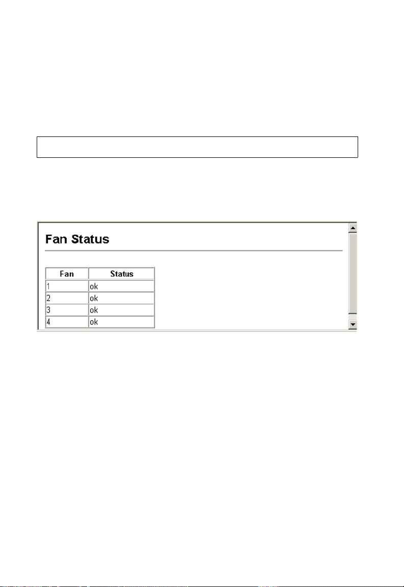
Fan Status
The status of the switch fans can be displayed.
Web – Click System, Fan Status.
Managing Firmware
You can upload/download firmware to or from a TFTP server. By saving runtime
code to a file on a TFTP server, that file can later be downloaded to the switch to
restore operation. You can also set the switch to use new firmware without
overwriting the previous version. The drop down menu in the web interface allows
you to specify the method of file transfer.
Command Attributes
• TFTP Server IP Address – The IP address of a TFTP server.
• File Name –
of the file name should not be a period (.), and the maximum length for file
names on the TFTP server is 127 characters or 31 characters for files on the
switch. (Valid characters: A-Z, a-z, 0-9, “.”, “-”, “_”)
• Destination/Startup File Name – Allows specification of filenames already in
memory, or the creation of a new filename. (Valid characters: A-Z, a-z, 0-9, “.”,
“-”, “_”)
• Source File Name – Allows you to specify the name of the chosen source file.
The file name should not contain slashes (\ or /),
3-14
the leading letter
Page 45

Basic Configuration
Note: Up to two copies of the system software (i.e., the runtime firmware) can be stored
in the file directory on the switch. The currently designated startup version of this
file cannot be deleted.
Downloading System Software from a Server
When downloading runtime code, you can specify the destination file name to
replace the current image, or first download the file using a different name from the
current runtime code file, and then set the new file as the startup file.
Web – Click System, Firmware. Enter the source and destination file names with
any other relevant details such as the IP address of the TFTP server if used, and
click Transfer from Server.
If you download to a new destination file, then select the file from the drop-down box
for the operation code used at startup, and click Apply Changes. To start the new
firmware, reboot the system via the System/Reset menu.
To remove an operating code file, select the file from the drop-down list and click
Remove File.
3-15
Page 46

Configuring the Switch
CLI – Enter the IP address of the TFTP server, select “config” or “opcode” file type,
then enter the source and destination file names, set the new file to start up the
system, and then restart the switch.
Console#copy tftp file 4-55
TFTP server ip address: 10.1.0.19
Choose file type:
1. config: 2. opcode: <1-2>: 2
Source file name: M100000.bix
Destination file name: V1.0
\Write to FLASH Programming.
-Write to FLASH finish.
Success.
Console#config
Console(config)#boot system opcode:V1.0 4-59
Console(config)#exit
Console#reload 4-20
Saving or Restoring Configuration Settings
You can upload/download configuration settings to/from a TFTP server. The
configuration file can be later downloaded to restore the switch’s settings.
Command Attributes
• TFTP Server IP Address – The IP address of a TFTP server.
• File Name
– The configuration file name should not contain slashes (\ or /),
leading letter of the file name should not be a period (.), and the maximum
length for file names on the TFTP server is 127 characters or 31 characters for
files on the switch. (Valid characters: A-Z, a-z, 0-9, “.”, “-”, “_”)
Note: The maximum number of user-defined configuration files is limited only by
available flash memory space.
the
Downloading Configuration Settings from a Server
You can download the configuration file under a new file name and then set it as the
startup file, or you can specify the current startup configuration file as the destination
file to directly replace it. Note that the file “Factory_Default_Config.cfg” can be
copied to the TFTP server, but cannot be used as the destination on the switch.
Web – Click System, Configuration. Enter the IP address of the TFTP server, enter
the name of the file to download, select a file on the switch to overwrite or specify a
new file name, and then click Transfer from Server.
3-16
Page 47

Basic Configuration
Setting the Startup Configuration File
If you download to a new file name, select the new file from the drop-down list for
Startup Configuration File, and press Apply Changes. To use the new settings,
reboot the system via the System/Reset menu.
CLI – Enter the IP address of the TFTP server, specify the source file on the server,
set the startup file name on the switch, and then restart the switch.
Console#copy tftp startup-config 4-55
TFTP server ip address: 192.168.1.19
Source configuration file name: config-1
Startup configuration file name [] : startup
\Write to FLASH Programming.
-Write to FLASH finish.
Success.
Console#reload
Copying the Running Configuration to a File
You can copy the running configuration to a file.
If you download the startup configuration file under a new file name, you can set this
file as the startup file at a later time, and then restart the switch.
Console#copy tftp startup-config 4-55
TFTP server ip address: 192.168.1.19
Source configuration file name: startup2.0
Startup configuration file name [startup] : startup2.0
/
Console#config
Console(config)#boot system config: startup-new 4- 59
Console(config)#exit
Console#reload 4-20
3-17
Page 48

Configuring the Switch
Resetting the System
Web – Click System, Reset. Click the Reset button to restart the switch.
CLI – Use the reload command to restart the switch.
Console#reload 4-20
System will be restarted, continue <y/n>?
Note: When restarting the system, it will always run the Power-On Self-Test.
Setting the System Clock
Simple Network Time Protocol (SNTP) allows the switch to set its internal clock
based on periodic updates from a time server (SNTP or NTP). Maintaining an
accurate time on the switch enables the system log to record meaningful dates and
times for event entries. You can also manually set the clock using the CLI.
(See “calendar set” on page 48.) If the clock is not set, the switch will only record the
time from the factory default set at the last bootup.
This switch acts as an SNTP client in two modes:
Unicast – The switch periodically sends a request for a time update to a configured
time server. You can configure up to three time server IP addresses. The switch will
attempt to poll each server in the configured sequence.
Broadcast – The switch sets its clock from a time server in the same subnet that
broadcasts time updates. If there is more than one SNTP server, the switch accepts
the first broadcast it detects and ignores broadcasts from other servers.
Configuring SNTP
You can configure the switch to send time synchronization requests to specific time
servers (i.e., client mode), update its clock using information broadcast from time
servers, or use both methods. When both methods are enabled, the switch will
update its clock using information broadcast from time servers, but will query the
specified server(s) if a broadcast is not received within the polling interval.
Command Attributes
• SNTP Client – Configures the switch to operate as an SNTP unicast client. This
mode requires at least one time server to be specified in the SNTP Server field.
• SNTP Broadcast Client – Configures the switch to operate as an SNTP
broadcast client.
3-18
Page 49

Basic Configuration
• SNTP Poll Interval – Sets the interval between sending requests for a time
update from a time server when set to SNTP Client mode.
(Range: 16-16284 seconds; Default: 16 seconds)
• SNTP Server – In unicast mode, sets the IP address for up to three time
servers. The switch attempts to update the time from the first server, if this fails
it attempts an update from the next server in the sequence.
Web – Select SNTP, Configuration. Modify any of the required parameters, and click
Apply.
CLI – This example configures the switch to operate as an SNTP client and as an
SNTP broadcast client.
Console(config)#sntp client 4-44
Console(config)#sntp poll 16 4-46
Console(config)#sntp server 10.1.0.19 137.82.140.80 128.250.36.2 4-45
Console(config)#sntp broadcast client 4-47
Console(config)#
Setting the Time Zone
SNTP uses Coordinated Universal Time (or UTC, formerly Greenwich Mean Time,
or GMT) based on the time at the Earth’s prime meridian, zero degrees longitude. To
display a time corresponding to your local time, you must indicate the number of
hours and minutes your time zone is east (before) or west (after) of UTC.
Command Attributes
• Current Time – Displays the current time.
• Name – Assigns a name to the time zone.
• Hours (0-12) – The number of hours before/after UTC.
• Minutes (0-59) – The number of minutes before/after UTC.
• Direction – Configures the time zone to be before (east) or after (west) UTC.
3-19
Page 50

Configuring the Switch
Web – Select SNTP, Clock Time Zone. Set the offset for your time zone relative to
the UTC, and click Apply.
CLI - This example shows how to set the time zone for the system clock.
Console(config)#clock timezone Dhaka hours 6 minute 0 after-UTC 4-48
Console#
Simple Network Management Protocol
Simple Network Management Protocol (SNMP) is a communication protocol
designed specifically for managing devices on a network. Equipment commonly
managed with SNMP includes switches, routers and host computers. SNMP is
typically used to configure these devices for proper operation in a network
environment, as well as to monitor them to evaluate performance or detect potential
problems.
The switch includes an onboard SNMP agent that continuously monitors the status
of its hardware, as well as the traffic passing through its ports. A network
management station can access this information using software such as HP
OpenView. Access rights to the onboard agent are controlled by community strings.
To communicate with the switch, the management station must first submit a valid
community string for authentication. The options for configuring community strings,
trap functions, and restricting access to clients with specified IP addresses are
described in the following sections.
3-20
Page 51

Simple Network Management Protocol
Setting Community Access Strings
You may configure up to five community strings authorized for management access.
All community strings used for IP Trap Managers should be listed in this table. For
security reasons, you should consider removing the default strings.
Command Attributes
• SNMP Community Capability – Indicates that the switch supports up to five
community strings.
• Community String – A community string that acts like a password and permits
access to the SNMP protocol.
Default strings: “public” (read-only access), “private” (read/write access)
Range: 1-32 characters, case sensitive
• Access Mode
- Read-Only – Specifies read-only access. Authorized management stations
are only able to retrieve MIB objects.
- Read/Write – Specifies read-write access. Authorized management stations
are able to both retrieve and modify MIB objects.
Web – Click SNMP, Configuration. Add new community strings as required, select
the access rights from the Access Mode drop-down list, then click Add.
CLI – The following example adds the string “spiderman” with read/write access.
Console(config)#snmp-server community spiderman rw 4-7 6
Console(config)#
3-21
Page 52

Configuring the Switch
Specifying Trap Managers and Trap Types
Traps indicating status changes are issued by the switch to specified trap managers.
You must specify trap managers so that key events are reported by this switch to
your management station (using network management platforms such as
HP OpenView. You can specify up to five management stations that will receive
authentication failure messages and other trap messages from the switch.
Command Attributes
• Trap Manager Capability – This switch supports up to five trap managers.
• Trap Manager IP Address – Internet address of the host (the targeted
recipient).
• Trap Manager Community String – Community string sent with the notification
operation. (Range: 1-32 characters, case sensitive)
• Trap Version – Specifies whether to send notifications as SNMP v1 or v2c
traps. (The default is version 1.)
• Enable Authentication Traps – Issues a trap message whenever an invalid
community string is submitted during the SNMP access authentication process.
(The default is enabled.)
• Enable Link-up and Link-down Traps – Issues link-up or link-down traps.
(The default is enabled.)
Web – Click SNMP, Configuration. Fill in the IP address and community string for
each trap manager that will receive these messages, specify the SNMP version,
mark the trap types required, and then click Add.
CLI – This example adds a trap manager and enables both authentication and
link-up, link-down traps.
Console(config)#snmp-server host 192.168.1.19 private version 2c 4-78
Console(config)#snmp-server enable traps 4-79
3-22
Page 53

Simple Network Management Protocol
Filtering Addresses for SNMP Client Access
The switch allows you to create a list of up to 16 IP addresses or IP address groups
that are allowed access to the switch via SNMP management software.
Command Usage
• To specify the clients allowed SNMP access, enter an IP address along with a
subnet mask to identify a specific host or a range of valid addresses. For
example:
- IP address 192.168.1.1 and mask 255.255.255.255 –
Specifies a valid IP address of 192.168.1.1 for a single client.
- IP address 192.168.1.1 and mask 255.255.255.0 –
Specifies a valid IP address group from 192.168.1.0 to 192.168.1.254.
• IP filtering only restricts management access for clients running SNMP
management software such as HP OpenView. It does not affect management
access to the switch using the web interface or Telnet.
• The default setting is null, which allows all IP groups SNMP access to the
switch. If one or more IP addresses are configured, IP filtering is enabled and
only addresses listed in this table will have SNMP access.
Command Attributes
• IP Filter List – Displays a list of the IP address/subnet mask entries currently
configured for SNMP access.
• IP address – Specifies a new IP address to add to the IP Filter List.
• Subnet Mask – Specifies a single IP address or group of addresses. If the IP is
the address of a single management station, set the mask to 255.255.255.255.
Otherwise, an IP address group will be specified by any other mask.
Web – Click SNMP, IP Filtering. To add a client, enter the new address, the subnet
mask for a node or an address range, and then click “Add IP Filtering Entry.”
3-23
Page 54

Configuring the Switch
CLI – This example allows SNMP access for a specific client.
Console(config)#snmp ip filter 10.1.2.3 255.255.255.255 4-80
Console(config)#
User Authentication.
Use the Passwords or RADIUS/TACACS+ menu to restrict management access
based on specified user names and passwords. You can manually configure access
rights on the switch (Passwords menu), or you can use a remote access
authentication server based on the RADIUS/TACACS+ protocol. You can also use
IEEE 802.1x port authentication to control access to specific ports (dot1X menu).
Configuring the Logon Password
The guest only has read access for most configuration parameters. However, the
administrator has write access for all parameters governing the onboard agent. You
should therefore assign a new administrator password as soon as possible, and
store it in a safe place.
The default guest name is “guest” with the password “guest.” The default
administrator name is “admin” with the password “admin.” Note that user names can
only be assigned via the CLI.
Command Attributes
• User Name* – The name of the user.
(Maximum length: 8 characters; maximum number of users: 5)
• Access Level* – Specifies the user level.
(Options: Normal and Privileged)
• Password – Specifies the user password.
(Range: 0-8 characters plain text, case sensitive)
* CLI only.
Web – Click Security, Passwords. Enter the old password, enter the new password,
confirm it by entering it again, then click Apply.
3-24
Page 55

User Authentication.
CLI – Assign a user name to access-level 15 (i.e., administrator), then specify the
password.
Console(config)#username bob access-level 15 4-24
Console(config)#username bob password 0 smith
Console(config)#
Configuring Local/Remote Logon Authentication
Use the Authentication Settings menu to restrict management access based on
specified user names and passwords. You can manually configure access rights on
the switch, or you can use a remote access authentication server based on RADIUS
or TACACS+ protocols.
Remote Authentication Dial-in
User Service (RADIUS) and
Terminal Access Controller Access
Control System Plus (TACACS+)
are logon authentication protocols
that use software running on a
central server to control access to
RADIUS-aware or TACACS
-aware devices on the network. An
authentication server contains a
database of multiple user name/
Web
Telnet
RADIUS/
TACACS+
server
1. Client attempts management access.
2. Switch contacts authentication server.
3. Authentication server challenges client.
4. Client responds with proper password or key.
5. Authentication server approves access.
6. Switch grants management access.
password pairs with associated
privilege levels for each user that requires management access to the switch.
RADIUS uses UDP while TACACS+ uses TCP. UDP only offers best effort delivery,
while TCP offers a connection-oriented transport. Also, note that RADIUS encrypts
only the password in the access-request packet from the client to the server, while
TACACS+ encrypts the entire body of the packet.
Command Usage
• By default, management access is always checked against the authentication
database stored on the local switch. If a remote authentication server is used,
you must specify the authentication sequence and the corresponding
parameters for the remote authentication protocol. Local and remote logon
authentication control management access via the console port, web browser,
or Telnet.
• RADIUS and TACACS+ logon authentication assign a specific privilege level for
each user name/password pair. The user name, password, and privilege level
must be configured on the authentication server.
• You can specify up to three authentication methods for any user to indicate the
authentication sequence. For example, if you select (1) RADIUS, (2) TACACS
and (3) Local, the user name and password on the RADIUS server is verified
first. If the RADIUS server is not available, then authentication is attempted
using the TACACS+ server, and finally the local user name and password is
checked.
console
3-25
Page 56

Configuring the Switch
Command Attributes
Authentication – Select the authentication, or authentication sequence
•
required:
- Local – User authentication is performed only locally by the switch.
- Radius – User authentication is performed using a RADIUS server only.
TACACS – User authentication is performed using a TACACS+ server only.
-
- [authentication sequence] – User authentication is performed by up to three
authentication methods in the indicated sequence.
• RADIUS Settings
- Server IP Address – Address of authentication server. (Default: 10.1.0.1)
- Server Port Number – Network (UDP) port of authentication server used for
authentication messages. (Range: 1-65535; Default: 1812)
- Secret Text String – Encryption key used to authenticate logon access for
client. Do not use blank spaces in the string. (Maximum length: 20 characters)
- Number of Server Transmits – Number of times the switch tries to
authenticate logon access via the authentication server.
(Range: 1-30; Default: 2)
- Timeout for a reply – The number of seconds the switch waits for a reply
from the RADIUS server before it resends the request.
(Range: 1-65535; Default: 5)
• TACACS Settings
- Server IP Address – Address of the TACACS+ server. (Default: 10.11.12.13)
- Server Port Number – Network (TCP) port of TACACS+ server used for
authentication messages. (Range: 1-65535; Default: 49)
- Secret Text String – Encryption key used to authenticate logon access for
client. Do not use blank spaces in the string. (Maximum length: 20 characters)
Note: The local switch user database has to be set up by manually entering user names
and passwords using the CLI. (See “username” on page 24.)
3-26
Page 57

User Authentication.
Web – Click Security, Authentication Settings. To configure local or remote
authentication preferences, specify the authentication sequence (i.e., one to three
methods), fill in the parameters for RADIUS or TACACS+ authentication if selected,
and click Apply.
CLI – Specify all the required parameters to enable logon authentication.
Console(config)#authentication login radius 4-60
Console(config)#radius-server host 192.168.1.25 4-61
Console(config)#radius-server port 181 4-62
Console(config)#radius-server key green 4-62
Console(config)#radius-server retransmit 5 4-63
Console(config)#radius-server timeout 10 4-63
Console#show radius-server 4-64
Server IP address: 192.168.1.25
Communication key with radius server:
Server port number: 181
Retransmit times: 5
Request timeout: 10
Console(config)#authentication login tacacs 4-60
Console(config)#tacacs-server host 10.20.30.40 4-64
Console(config)#tacacs-server port 200 4-65
Console(config)#tacacs-server key green 4-65
Console#show tacacs-server 4-66
Server IP address: 10.20.30.40
Communication key with tacacs server: green
Server port number: 200
Console(config)#
3-27
Page 58

Configuring the Switch
Telnet Settings
Telnet access to the switch can be enabled via the Web or CLI.
Web – Click Security, Telnet Settings, then check the checkbox to enable access via
Telnet (i.e., a virtual terminal).
CLI – This example enables Telnet access to the switch.
Console#config 4-30
Console(config)#ip telnet server
Console(config-line)#
Configuring HTTPS
You can configure the switch to enable the Secure Hypertext Transfer Protocol
(HTTPS) over the Secure Socket Layer (SSL), providing secure access (i.e., an
encrypted connection) to the switch’s web interface.
Command Usage
• Both the HTTP and HTTPS service can be enabled independently on the
switch. However, you cannot configure both services to use the same UDP port.
• If you enable HTTPS, you must indicate this in the URL that you specify in your
browser: https://device[:port_number]
• When you start HTTPS, the connection is established in this way:
- The client authenticates the server using the server’s digital certificate.
- The client and server negotiate a set of security protocols to use for the
connection.
- The client and server generate session keys for encrypting and decrypting
data.
• The client and server establish a secure encrypted connection.
A padlock icon should appear in the status bar for Internet Explorer 5.x or above
and Netscape Navigator 4.x or above.
• The following web browsers and operating systems currently support HTTPS:
Web Browser Operating System
Internet Explorer 5.0 or later Windows 98,Windows NT (with service pack 6a),
Netscape Navigator 4.76 or later Windows 98,Windows NT (with service pack 6a),
• To specify a secure-site certificate, see “Replacing the Default Secure-site
Certificate” on page 3-29.
Windows 2000, Windows XP
Windows 2000, Windows XP, Solaris 2.6
3-28
Page 59

User Authentication.
Command Attributes
HTTPS Status – Allows you to enable/disable the HTTPS server feature on the
•
switch.
(Default: Enabled)
•
Change HTTPS Port Number – Specifies the UDP port number used for HTTPS/
SSL connection to the switch’s web interface. (Default: Port 443)
Web – Click Security, HTTPS Settings. Enable HTTPS and specify the port number,
then click Apply.
CLI – This example enables the HTTP secure server and modifies the port number.
Console(config)#ip http secure-server 4-29
Console(config)#ip http secure-port 441 4-30
Console(config)#
Replacing the Default Secure-site Certificate
When you log onto the web interface using HTTPS (for secure access), a Secure
Sockets Layer (SSL) certificate appears for the switch. By default, the certificate that
Netscape and Internet Explorer display will be associated with a warning that the
site is not recognized as a secure site. This is because the certificate has not been
signed by an approved certification authority. If you want this warning to be replaced
by a message confirming that the connection to the switch is secure, you must
obtain a unique certificate and a private key and password from a recognized
certification authority.
Caution: For maximum security, we recommend you obtain a unique Secure Sockets
Layer certificate at the earliest opportunity. This is because the default
certificate for the switch is not unique to the hardware you have purchased.
When you have obtained these, place them on your TFTP server, and use the
following command at the switch's command-line interface to replace the default
(unrecognized) certificate with an authorized one:
Console#copy tftp https-certificate 4-55
TFTP server ip address: <server ip-address>
Source certificate file name: <certificate file name>
Source private file name: <private key file name>
Private password: <password for private key>
Note: The switch must be reset for the new certificate to be activated. To reset the
switch, type:
Console#reload
3-29
Page 60

Configuring the Switch
Configuring the Secure Shell
The Berkley-standard includes remote access tools originally designed for Unix
systems. Some of these tools have also been implemented for Microsoft Windows
and other environments. These tools, including commands such as, rsh (remote
shell), and rexec (remote execute), are not secure from hostile attacks.
The Secure Shell (SSH) includes server/client applications intended as a secure
replacement for the older Berkley remote access tools. SSH provides remote
management access via encrypted paths between the switch and SSH-enabled
management station clients. The commands described in this section include
commands used to configure the SSH server. However, you also need to install a
SSH client on the management station when using this protocol to configure the
switch. When the client contacts the switch via the SSH protocol, the switch
generates a public-key that the client uses along with a local user name and
password for access authentication.
Note: The switch supports only SSH Version 1.5.
Command Attributes
• SSH Server Status – Allows you to enable/disable the SSH server feature on
the switch. (Default: Enabled)
• SSH Authentication Timeout – Specifies the time interval in seconds that the
SSH server waits for a response from a client during an authentication attempt.
• (Range: 1 to 120 seconds; Default: 120 seconds)
• SSH Authentication Retries – Specifies the number of authentication attempts
that a client is allowed before authentication fails and the client has to restart the
authentication process. (Range: 1-5 times; Default: 3)
Web – Click Security, SSH, Settings. Enable SSH and adjust the authentication
parameters as required, then click Apply.
3-30
Page 61

User Authentication.
CLI – This example enables SSH, sets the authentication parameters, and displays
the current configuration. It shows that the administrator has made a connection via
SHH, and then disabled this connection.
Console(config)#ip ssh server 4-31
Console(config)#ip ssh timeout 100 4-35
Console(config)#ip ssh authentication-retries 5 4-33
Console(config)#
Console#show ip ssh 4-34
Information of secure shell
SSH status: enable
SSH authentication timeout: 100
SSH authentication retries: 5
Console#show ssh 4-35
Information of secure shell
Session Username Version Encrypt method Negotiation state
------- -------- ------- -------------- -----------------
0 admin 1.5 cipher-3des session-started
Console#disconnect ssh 0 4-16
Console#
Configuring Port Security
Port security is a feature that allows you to configure a switch port with one or more
device MAC addresses that are authorized to access the network through that port.
When port security is enabled on a port, the switch stops learning new MAC
addresses on the specified port. Only incoming traffic with source addresses already
stored in the dynamic or static address table will be accepted as authorized to
access the network through that port. If a device with an unauthorized MAC address
attempts to use the switch port, the intrusion will be detected and the switch can
automatically take action by disabling the port and sending a trap message.
To use port security, first allow the switch to dynamically learn the <source MAC
address, VLAN> pair for frames received on a port for an initial training period, and
then enable port security to stop address learning. Be sure you enable the learning
function long enough to ensure that all valid VLAN members have been registered
on the selected port. Note that you can also restrict the maximum number of
addresses that can be learned by a port.
To add new VLAN members at a later time, you can manually add secure addresses
with the Static Address Table (page 3-73), or turn off port
learning function long enough for new VLAN members
may then be disabled again, if desired, for security.
Command Usage
• A secure port has the following restrictions:
- It cannot use port monitoring.
- It cannot be a multi-VLAN port.
- It cannot be used as a member of a static or dynamic trunk.
- It should not be connected to a network interconnection device.
• If a port is disabled (shut down) due to a security violation, it must be manually
re-enabled from the Port/Port Configuration page (page 3-42).
security to reenable the
to be registered. Learning
3-31
Page 62
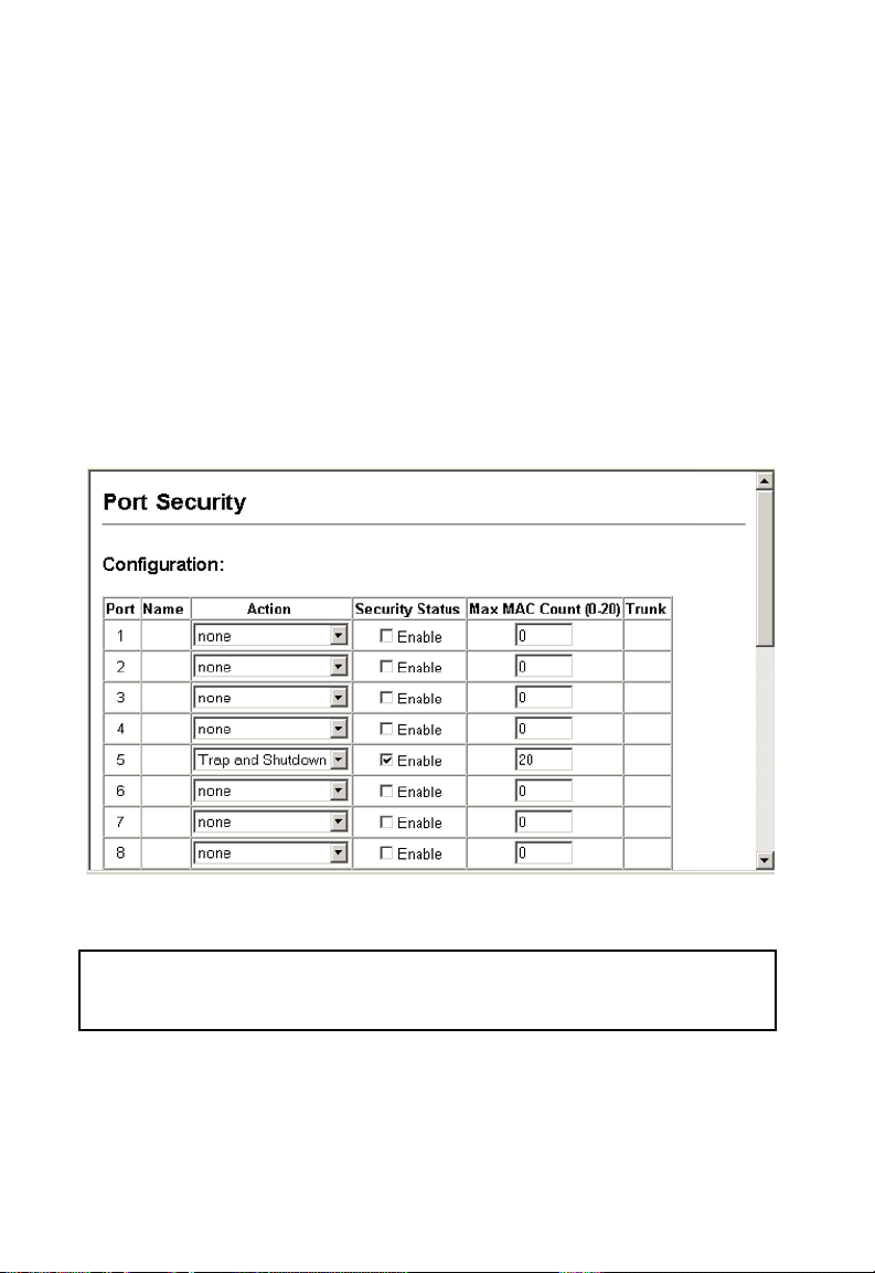
Configuring the Switch
Command Attributes
Port – Port number.
•
•
Action* – The action to be taken when a port security violation is detected:
- None: No action should be taken. (This is the default.)
- Trap: Send an SNMP trap message.
- Shutdown: Disable the port.
- Trap and Shutdown: Send an SNMP trap message and disable the port.
Status – Enables or disables port security on the port. (Default: Disabled)
•
•
Max MAC Count – The maximum number of MAC addresses that can be
learned on a port. (Range: 0 - 20)
* These actions can only be taken through CLI commands.
Web – Click Security, Port Security. Set the action to take when an invalid address is
detected on a port, select Enabled from the drop-down list in the Status column to
enable security for a port, set the maximum number of MAC addresses allowed on a
port, and click Apply.
CLI – This example sets the command mode to Port 5, sets the port security action
to send a trap and disable the port, and then enables port security for the switch.
Console(config)#interface ethernet 1/5
Console(config-if)#port security action trap-and-shutdown 4-67
Console(config-if)#port security
Console(config-if)#
3-32
Page 63
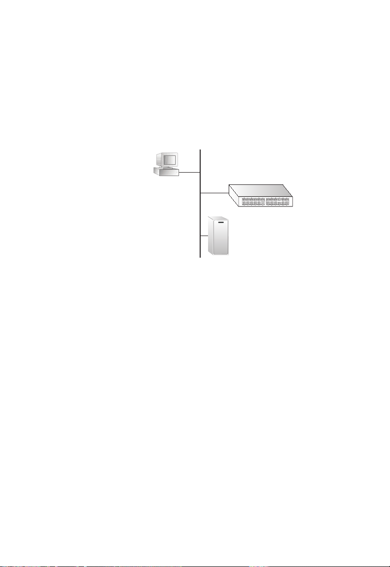
User Authentication.
Configuring 802.1x Port Authentication
Network switches can provide open and easy access to network resources by
simply attaching a client PC. Although this automatic configuration and access is a
desirable feature, it also allows unauthorized personnel to easily intrude and
possibly gain access to sensitive network data.
The IEEE 802.1x (dot1x) standard defines a port-based access control procedure
that prevents unauthorized access to a network by requiring users to first submit
credentials for authentication. Access to all switch ports in a network can be
centrally controlled from a server, which means that authorized users can use the
same credentials for authentication from any point within the network.
This switch uses the
Extensible Authentication
Protocol over LANs
(EAPOL) to exchange
authentication protocol
messages with the client,
and a remote RADIUS
authentication server to
verify user identity and
access rights. When a
client (i.e., Supplicant)
connects to a switch port,
the switch (i.e., Authenticator) responds with an EAPOL identity request. The client
provides its identity (such as a user name) in an EAPOL response to the switch,
which it forwards to the RADIUS server. The RADIUS server verifies the client
identity and sends an access challenge back to the client. The EAP packet from the
RADIUS server contains not only the challenge, but the authentication method to be
used. The client can reject the authentication method and request another,
depending on the configuration of the client software and the RADIUS server. The
authentication method can be MD5, TLS (Transport Layer Security), TTLS
(Tunneled Transport Layer Security), or other. The client responds to the appropriate
method with its credentials, such as a password or certificate. The RADIUS server
verifies the client credentials and responds with an accept or reject packet. If
authentication is successful, the switch allows the client to access the network.
Otherwise, network access is denied and the port remains blocked.
The operation of 802.1x on the switch requires the following:
• The switch must have an IP address assigned.
• RADIUS authentication must be enabled on the switch and the IP address of the
RADIUS server specified.
• Each switch port that will be used must be set to dot1x “Auto” mode.
• Each client that needs to be authenticated must have dot1x client software
installed and properly configured.
• The RADIUS server and 802.1x client support EAP. (The switch only supports
EAPOL in order to pass the EAP packets from the server to the client.)
• The RADIUS server and client also have to support the same EAP
authentication type – MD5, TLS, TTLS, PEAP, etc. (Some clients have native
support in Windows, otherwise the dot1x client must support it.)
802.1x
client
RADIUS
server
1. Client attempts to access a switch port.
2. Switch sends client an identity request.
3. Client sends back identity information.
4. Switch forwards this to authentication server.
5. Authentication server challenges client.
6. Client responds with proper credentials.
7. Authentication server approves access.
8. Switch grants client access to this port.
3-33
Page 64

Configuring the Switch
Displaying 802.1x Global Settings
The dot1x protocol includes global parameters that control the client authentication
process that runs between the client and the switch (i.e., authenticator), as well as
the client identity lookup process that runs between the switch and authentication
server. These parameters are described in this section.
Command Attributes
• 802.1x Re-authentication – Indicates if switch port requires a client to be
re-authenticated after a certain period of time.
• 802.1x Max Request Count – The maximum number of times the switch port
will retransmit an EAP request packet to the client before it times out the
authentication session.
• Timeout for Quiet Period – Indicates the time that a switch port waits after the
Max Request Count has been exceeded before attempting to acquire a new
client.
• Timeout for Re-authentication Period – Indicates the time period after which
a connected client must be re-authenticated.
• Timeout for TX Period – The time period during an authentication session that
the switch waits before re-transmitting an EAP packet.
• Supplicant timeout – The time the switch waits for a client response to an EAP
request.
• Server timeout – The time the switch waits for a response from the
authentication server (RADIUS) to an authentication request.
• Re-authentication Max Count – The number of times the switch will attempt to
re-authenticate a connected client before the port becomes unauthorized.
Web – Click Security, 802.1x, Information.
3-34
Page 65

User Authentication.
CLI – This example shows the default protocol settings for 802.1x. For a description
of the additional entries displayed in the CLI, See “show dot1x” on page 73.
Console#show dot1x 4-73
Global 802.1X Parameters
reauth-enabled: yes
reauth-period: 300
quiet-period: 350
tx-period: 300
supp-timeout: 30
server-timeout: 30
reauth-max: 2
max-req: 2
802.1X Port Summary
Port Name Status Operation Mode Mode Authorized
1/1 disabled Single-Host ForceAuthorized n/a
1/2 disabled Single-Host ForceAuthorized n/a
.
.
.
1/11 disabled Single-Host ForceAuthorized yes
1/12 enabled Single-Host Auto yes
802.1X Port Details
802.1X is disabled on port 1
.
.
.
802.1X is enabled on port 12
Status Unauthorized
Operation mode Single-Host
Max count 5
Port-control Auto
Supplicant 00-00-00-00-00-00
Current Identifier 0
Authenticator State Machine
State Connecting
Reauth Count 3
Backend State Machine
State Idle
Request Count 0
Identifier(Server) 0
Reauthentication State Machine
State Initialize
Console#
3-35
Page 66

Configuring the Switch
Configuring 802.1x Global Settings
The dot1x protocol includes global parameters that control the client authentication
process that runs between the client and the switch (i.e., authenticator), as well as
the client identity lookup process that runs between the switch and authentication
server. The configuration options for parameters are described in this section.
Command Attributes
• 802.1x Re-authentication – Sets the client to be re-authenticated after the
interval specified by the Timeout for Re-authentication Period.
Re-authentication can be used to detect if a new device is plugged into a switch
port. (Default: Disabled)
• 802.1x Max Request Count – Sets the maximum number of times the switch
port will retransmit an EAP request packet to the client before it times out the
authentication session. (Range: 1-10; Default 2)
• Timeout for Quiet Period – Sets the time that a switch port waits after the
dot1X Max Request Count has been exceeded before attempting to acquire a
new client. (Range: 1-65535 seconds; Default: 60 seconds)
• Timeout for Re-authentication Period – Sets the time period after which a
connected client must be re-authenticated. (Range: 1-65535 seconds;
Default: 3600 seconds)
• Timeout for TX Period – Sets the time period during an authentication session
that the switch waits before re-transmitting an EAP packet. (Range: 1-65535;
Default: 30 seconds)
• authentication dot1x default* – Sets the default authentication server type.
Note that the specified authentication server type must be enabled and properly
configured for dot1x to function properly. (Options: radius).
* CLI only.
Web – Select Security, 802.1x, Configuration. Enable dot1x globally for the switch,
modify any of the parameters required, and then click Apply.
3-36
Page 67

User Authentication.
CLI
– This enables re-authentication and sets all of the global parameters for 802.1x
Console(config)#dot1x re-authentication 4-71
Console(config)#dot1x max-req 5 4-69
Console(config)#dot1x timeout quiet-period 40 4-71
Console(config)#dot1x timeout re-auth 5 4-72
Console(config)#dot1x timeout tx-period 40 4-72
Console(config)#authentication dot1x default radius 4-69
Console(config)#
Configuring Port Authorization Mode
When dot1x is enabled, you need to specify the dot1x authentication mode
configured for each port.
Command Attributes
• Status – Indicates if authentication is enabled or disabled on the port.
• Operation Mode – Allows single or multiple hosts (clients) to connect to an
802.1X-authorized port. (Range: Single-Host, Multi-Host; Default: Single-Host)
• Max Count – The maximum number of hosts that can connect to a port when
the Multi-Host operation mode is selected. (Range: 1-20; Default: 5)
• Mode – Sets the authentication mode to one of the following options:
- Auto – Requires a dot1x-aware client to be authorized by the authentication
server. Clients that are not dot1x-aware will be denied access.
- Force-Authorized – Forces the port to grant access to all clients, either
dot1x-aware or otherwise.
- Force-Unauthorized – Forces the port to deny access to all clients, either
dot1x-aware or otherwise.
• Authorized
- Yes – Connected client is authorized.
- No – Connected client is not authorized.
- Blank – Displays nothing when dot1x is disabled on a port.
• Supplicant – Indicates the MAC address of a connected client.
• Trunk – Indicates if the port is configured as a trunk port.
Web – Click Security, 802.1x, Port Configuration. Select the authentication mode
from the drop-down box and click Apply.
.
3-37
Page 68

Configuring the Switch
CLI – This example sets the authentication mode to enable 802.1x on port 2, and
allows up to ten clients to connect to this port.
Console(config)#interface ethernet 1/2 4-84
Console(config-if)#dot1x port-control auto 4-70
Console(config-if)#dot1x operation-mode multi-host max-count 10 4-70
Console(config-if)#
Displaying 802.1x Statistics
This switch can display statistics for dot1x protocol exchanges for any port.
Statistical Values
Parameter Description
Rx EXPOL Start The number of EAPOL Start frames that have been received by this
Rx EAPOL Logoff The number of EAPOL Logoff frames that have been received by this
Rx EAPOL Invalid The number of EAPOL frames that have been received by this
Rx EAPOL Total The number of valid EAPOL frames of any type that have been received
Rx EAP Resp/Id The number of EAP Resp/Id frames that have been received by this
Rx EAP Resp/Oth The number of valid EAP Response frames (other than Resp/Id frames)
Rx EAP LenError The number of EAPOL frames that have been received by this
Rx Last EAPOLVer The protocol version number carried in the most recently received EAPOL
Rx Last EAPOLSrc The source MAC address carried in the most recently received EAPOL
Tx EAPOL Total The number of EAPOL frames of any type that have been transmitted by
Tx EAP Req/Id The number of EAP Req/Id frames that have been transmitted by this
Tx EAP Req/Oth The number of EAP Request frames (other than Rq/Id frames) that have
Authenticator.
Authenticator.
Authenticator in which the frame type is not recognized.
by this Authenticator.
Authenticator.
that have been received by this Authenticator.
Authenticator in which the Packet Body Length field is invalid.
frame.
frame.
this Authenticator.
Authenticator.
been transmitted by this Authenticator.
Web – Select Security, 802.1x, Statistics. Select the required port and then click
Query. Click Refresh to update the statistics.
3-38
Page 69

Port Configuration
CLI – This example displays the 802.1x statistics for port 4.
Console#show dot1x statistics interface ethernet 1/4 4-73
Eth 1/4
Rx: EXPOL EAPOL EAPOL EAPOL EAP EAP EAP
Start Logoff Invalid Total Resp/Id Resp/Oth LenError
2 0 0 1007 672 0 0
Last Last
EAPOLVer EAPOLSrc
1 00-00-E8-98-73-21
Tx: EAPOL EAP EAP
Total Req/Id Req/Oth
2017 1005 0
Console#
Port Configuration
Displaying Connection Status
You can use the Port Information or Trunk Information pages to display the current
connection status, including link state, speed/duplex mode, flow control, and
auto-negotiation.
Field Attributes (Web)
Name – Interface label.
•
• Type – Indicates the port type.
(1000BASE-T, 1000BASE-SX, 1000BASE-LX, or 100BASE-TX)
•
Admin Status – Shows if the interface is enabled or disabled.
•
Oper Status – Indicates if the link is Up or Down.
3-39
Page 70

Configuring the Switch
• Max MAC Count – Shows the maximum number of MAC address that can be
learned by a port. (0 - 20 addresses)
•
Speed Duplex Status – Shows the current speed and duplex mode.
Flow Control Status – Indicates the type of flow control currently in use.
•
(IEEE 802.3x, Back-Pressure or None)
• Autonegotiation – Shows if auto-negotiation is enabled or disabled.
1
• Trunk Member
• Creation
– Shows if port is a trunk member.
2
– Shows if a trunk is manually configured or dynamically set via
LACP.
1: Port Information only.
2: Trunk Information only
Web – Click Port, Port Information or Trunk Information.
Command Attributes (CLI)
Basic information:
Port type – Indicates the port type.
•
(1000BASE-T, 1000BASE-SX, 1000BASE-LX, or 100BASE-TX)
• MAC address – The physical layer address for this port. (To access this item on
the web, see “Setting the Switch’s IP Address” on page 3-11.)
Configuration:
Name – Interface label.
•
• Port admin – Shows if the interface is enabled or disabled (i.e., up or down).
•
Speed-duplex
– Shows the current speed and duplex mode. (Auto, or fixed
choice)
• Capabilities – Specifies the capabilities to be advertised for a port during
auto-negotiation. (To access this item on the web, see “Configuring Interface
Connections” on page 3-48.) The following capabilities are supported.
- 10half - Supports 10 Mbps half-duplex operation
3-40
Page 71

Port Configuration
- 10full - Supports 10 Mbps full-duplex operation
- 100half - Supports 100 Mbps half-duplex operation
- 100full - Supports 100 Mbps full-duplex operation
- 1000full - Supports 1000 Mbps full-duplex operation
- Sym - Transmits and receives pause frames for flow control
- FC - Supports flow control
•
Broadcast storm – Shows if broadcast storm control is enabled or disabled.
• Broadcast storm limit – Shows the broadcast storm threshold. (500 - 262143
packets per second)
•
Flow control – Shows if flow control is enabled or disabled.
• LACP
– Shows if LACP is enabled or disabled.
• Port Security – Shows if port security is enabled or disabled.
• Max MAC count
– Shows the maximum number of MAC address that can be
learned by a port. (0 - 20 addresses)
• Port security action – Shows the response to take when a security violation is
detected. (none, shutdown, trap, trap-and-shutdown)
• Combo forced mode
combination ports
– Shows the forced/preferred port type to use for
21-24. (copper forced, copper preferred auto, SFP forced, SFP
preferred auto)
Current status:
• Link Status – Indicates if the link is up or down.
• Operation speed-duplex – Shows the current speed and duplex mode.
• Port Operation Status – Indicates if the link is Up or Down.
Flow control type – Indicates the type of flow control currently in use.
•
(IEEE 802.3x, Back-Pressure or none)
3-41
Page 72

Configuring the Switch
CLI – This example shows the connection status for Port 5.
Console#show interfaces status ethernet 1/5 4-91
Information of Eth 1/5
Basic information:
Port type: 1000T
Mac address: 00-30-f1-47-58-46
Configuration:
Name:
Port admin: Up
Speed-duplex: Auto
Capabilities: 10half, 10full, 100half, 100full, 1000full,
Broadcast storm: Enabled
Broadcast storm limit: 500 packets/second
Flow control: Disabled
Lacp: Disabled
Port security: Disabled
Max MAC count: 0
Port security action: None
Combo forced mode: None
Current status:
Link status: Down
Port operation status: Up
Operation speed-duplex: 100full
Flow control type: None
Console#
Configuring Interface Connections
You can use the Port Configuration or Trunk Configuration page to enable/disable an
interface, set auto-negotiation and the interface capabilities to advertise, or manually
fix the speed, duplex mode, and flow control.
Command Attributes
Name – Allows you to label an interface. (Range: 1-64 characters)
•
• Admin – Allows you to manually disable an interface. You can disable an
interface due to abnormal behavior (e.g., excessive collisions), and then
reenable it after the problem has been resolved. You may also disable an
interface for security reasons.
•
Speed/Duplex – Allows you to manually set the port speed and duplex mode.
Flow Control – Allows automatic or manual selection of flow control.
•
3-42
Page 73

Port Configuration
• Autonegotiation (Port Capabilities) – Allows auto-negotiation to be enabled/
disabled. When auto-negotiation is enabled, you need to specify the capabilities
to be advertised. When auto-negotiation is disabled, you can force the settings
for speed, mode, and flow control.The following capabilities are supported.
- 10half - Supports 10 Mbps half-duplex operation
- 10full - Supports 10 Mbps full-duplex operation
- 100half - Supports 100 Mbps half-duplex operation
- 100full - Supports 100 Mbps full-duplex operation
- 1000full - Supports 1000 Mbps full-duplex operation
- Sym (Gigabit only) - Check this item to transmit and receive pause frames, or
clear it to auto-negotiate the sender and receiver for asymmetric pause
frames. (The current switch chip only supports symmetric pause frames.)
- FC - Supports flow control
Flow control can eliminate frame loss by “blocking” traffic from end stations or
segments connected directly to the switch when its buffers fill. When enabled,
back pressure is used for half-duplex operation and IEEE 802.3x for
full-duplex operation. (Avoid using flow control on a port connected to a hub
unless it is actually required to solve a problem. Otherwise back pressure
jamming signals may degrade overall performance for the segment attached
to the hub.)
(Default: Autonegotiation enabled; Advertised capabilities for 1000BASE-T –
10half, 10full, 100half, 100full, 1000full; 1000BASE-SX/LX/LH – 1000full;
100BASE-TX – 100full)
•
Trunk – Indicates if a port is a member of a trunk. To create trunks and select
port members, see “Creating Trunk Groups” on page 3-44.
Note: Auto-negotiation must be disabled before you can configure or force the interface
to use the Speed/Duplex Mode or Flow Control options.
Web – Click Port, Port Configuration or Trunk Configuration. Modify the required
interface settings, and click Apply.
3-43
Page 74

Configuring the Switch
CLI – Select the interface, and then enter the required settings.
Console(config)#interface ethernet 1/12 4-84
Console(config-if)#description RD SW#12 4-85
Console(config-if)#shutdown 4-89
.
Console(config-if)#no shutdown
Console(config-if)#no negotiation 4-86
Console(config-if)#speed-duplex 100half 4-85
Console(config-if)#flowcontrol 4-88
.
Console(config-if)#negotiation
Console(config-if)#capabilities 100half 4-87
Console(config-if)#capabilities 100full
Console(config-if)#capabilities flowcontrol
Console(config-if)#exit
Creating Trunk Groups
You can create multiple links between devices that work as one virtual, aggregate
link. A port trunk offers a dramatic increase in bandwidth for network segments
where bottlenecks exist, as well as providing a fault-tolerant link between two
devices. You can create one trunk with two Gigabit optional module ports.
The switch supports both static trunking and dynamic Link Aggregation Control
Protocol (LACP). Static trunks have to be manually configured at both ends of the
link, and the switches must comply with the Cisco EtherChannel standard. On the
other hand, LACP configured ports can automatically negotiate a trunked link with
LACP-configured ports on another device. You can configure two Gigabit optional
module ports as LACP, as long as they are not already configured as part of a static
trunk. If ports on another device are also configured as LACP, the switch and the
other device will negotiate a trunk link between them.
Command Usage
Besides balancing the load across each port in the trunk, the other ports provide
redundancy by taking over the load if a port in the trunk fails. However, before
making any physical connections between devices, use the web interface or CLI to
specify the trunk on the devices at both ends. When using a port trunk, take note of
the following points:
• Finish configuring port trunks before you connect the corresponding network
cables between switches to avoid creating a loop.
• You can create one trunk with two Gigabit optional module ports.
• The ports at both ends of a connection must be configured as trunk ports.
• When configuring static trunks on switches of different types, they must be
compatible with the Cisco EtherChannel standard.
• The ports at both ends of a trunk must be configured in an identical manner,
including communication mode (i.e., speed, duplex mode and flow control),
VLAN assignments, and CoS settings.
• All the ports in a trunk have to be treated as a whole when moved from/to, added
or deleted from a VLAN.
• STP, VLAN, and IGMP settings can only be made for the entire trunk.
3-44
Page 75

Port Configuration
Statically Configuring a Trunk
Command Usage
• When configuring static trunks, you may not
be able to link switches of different types,
depending on the manufacturer’s
implementation. However, note that the
static trunks on this switch are Cisco
EtherChannel compatible.
• To avoid creating a loop in the network, be
sure you add a static trunk via the
configuration interface before connecting
the ports, and also disconnect the ports
before removing a static trunk via the
configuration interface.
Web – Click Port, Trunk Membership. Enter a trunk ID of 1-6 in the Trunk field,
select any of the switch ports from the scroll-down port list, and click Add. After you
have completed adding ports to the member list, click Apply.
active
links
statically
configured
}
3-45
Page 76

Configuring the Switch
CLI – This example creates trunk 2 with ports 13 and 14. Just connect these ports to
two static trunk ports on another switch to form a trunk.
Console(config)#interface port-channel 1 4-84
Console(config-if)#exit
Console(config)#interface ethernet 1/13 4-84
Console(config-if)#channel-group 1 4-99
Console(config-if)#exit
Console(config)#interface ethernet 1/14
Console(config-if)#channel-group 1
Console(config-if)#end
Console#show interfaces status port-channel 1 4-91
Information of Trunk 1
Basic information:
Port type: 1000GBIC
Mac address: 00-01-00-02-00-10
Configuration:
Name:
Port admin: Up
Speed-duplex: Auto
Capabilities: 1000full,
Flow control: Disabled
Port security: Disabled
Max MAC count: 0
Current status:
Created by: User
Link status: Down
Operation speed-duplex: 1000full
Flow control type: None
Member Ports: Eth1/13, Eth1/14,
Console#
Enabling LACP on Selected Ports
Command Usage
• To avoid creating a loop in the network, be sure
you enable LACP before connecting the ports,
and also disconnect the ports before disabling
LACP.
• If the target switch has also enabled LACP on
the connected ports, the trunk will be activated
active
links
automatically.
• A trunk formed with another switch using LACP
will automatically be assigned the next
available trunk ID.
• If more than four ports attached to the same target switch have LACP enabled,
the additional ports will be placed in standby mode, and will only be enabled if
one of the active links fails.
• All ports on both ends of an LACP trunk must be configured for full duplex, either
by forced mode or auto-negotiation.
dynamically
enabled
}
}
configured
members
backup
link
3-46
Page 77

Port Configuration
Web – Click Port, LACP, Configuration. Select switch ports from the scroll-down port
list and click Add. After you have completed adding ports to the member list, click
Apply.
CLI – The following example enables LACP for ports 13 and 14. Just connect these
ports to LACP-enabled trunk ports on another switch to form a trunk.
Console(config)#interface ethernet 1/13 4-84
Console(config-if)#lacp 4-99
Console(config-if)#exit
Console(config)#interface ethernet 1/14
Console(config-if)#lacp
Console(config-if)#end
Console#show interfaces status port-channel 1 4-91
Information of Trunk 1
Basic information:
Port type: 1000GBIC
Mac address: 22-22-22-22-22-2d
Configuration:
Name:
Port admin status: Up
Speed-duplex: Auto
Capabilities: 1000full,
Flow control status: Disabled
Port security: Disabled
Max MAC count: 0
Port security action: None
Combo forced mode: None
Current status:
Created by: Lacp
Link status: Up
Port operation status: Up
Operation speed-duplex: 1000full
Flow control type: None
Member Ports: Eth1/3, Eth1/14,
Console#
3-47
Page 78

Configuring the Switch
Setting Broadcast Storm Thresholds
Broadcast storms may occur when a device on your network is malfunctioning, or if
application programs are not well designed or properly configured. If there is too
much broadcast traffic on your network, performance can be severely degraded or
everything can come to complete halt.
You can protect your network from broadcast storms by setting a threshold for
broadcast traffic for each port. Any broadcast packets exceeding the specified
threshold will then be dropped.
Command Usage
• Broadcast Storm Control is enabled by default.
• The default threshold is 500 packets per second.
• Broadcast control does not effect IP multicast traffic.
• The specified threshold applies to all ports on the switch.
Command Attributes
• Threshold – Threshold in packets per second. (Options: 500-262143 packets
per second; Default: 500 packets per second)
• Broadcast Control Status – Shows whether or not broadcast storm control has
been enabled. (Default: Enabled)
Web – Click Port, Broadcast Control. Set the threshold, set Broadcast Control Status
to enabled, then click
Apply.
3-48
Page 79

Port Configuration
CLI – Specify any interface, and then enter the threshold. The following disables
broadcast storm control for port 1, and then sets broadcast suppression at 600
packets per second for port 2. This threshold will then apply to all ports with
broadcast storm control enabled.
Console(config)#interface ethernet 1/1 4-84
Console(config-if)#no switchport broadcast 4-89
Console(config-if)#exit
Console(config)#interface ethernet 1/2
Console(config-if)#switchport broadcast packet-rate 600 4-89
Console(config-if)#end
Console#show interfaces switchport ethernet 1/2
Information of Eth 1/2
Broadcast threshold: Enabled, 600 packets/second
Lacp status: Disabled
Ingress rate limit: disable,100M bits per second
Egress rate limit: disable,100M bits per second
VLAN membership mode: Hybrid
Ingress rule: Disabled
Acceptable frame type: All frames
Native VLAN: 1
Priority for untagged traffic: 0 Allowed Vlan: 1(u),
Forbidden Vlan:
Console#
Configuring Port Mirroring
You can mirror traffic from any source port to a
target port for real-time analysis. You can then
attach a logic analyzer or RMON probe to the
target port and study the traffic crossing the
source port in a completely unobtrusive manner.
Command Usage
• Monitor port speed should match or exceed source port speed, otherwise traffic
may be dropped from the monitor port.
• All mirror sessions have to share the same destination port.
• When mirroring port traffic, the target port must be included in the same VLAN
as the source port.
Command Attributes
• Mirror Sessions – Displays a list of current mirror sessions.
• Source Unit – The switch containing the mirror source port. This switch does
not support stacking , so this number will always be 1.
• Source Port – The port whose traffic will be monitored.
• Type – Allows you to select which traffic to mirror to the target port, Rx (receive),
Tx (transmit), or Both.
• Target Unit – The switch containing the mirror target port. This switch does not
support stacking , so this number will always be 1.
• Target Port – The port that will “duplicate” or “mirror” the traffic on the source
port.
Source
port(s)
Single
target
port
3-49
Page 80

Configuring the Switch
Web – Click Port, Mirror. Specify the source port, the traffic type to be mirrored, and
the target port, then click
CLI – Use the interface command to select the monitor port, then use the port
monitor command to specify the source port. Note that default mirroring under the
CLI is for both received and transmitted packets.
Console(config)#interface ethernet 1/10 4-84
Console(config-if)#port monitor ethernet 1/13 4- 95
Console(config-if)#
Add.
Configuring Rate Limits
This function allows the network manager to control the maximum rate for traffic
transmitted or received on an interface. Rate limiting is configured on interfaces at
the edge of a network to limit traffic coming out of the switch. Traffic that falls within
the rate limit is transmitted, while packets that exceed the acceptable amount of
traffic are dropped.
Rate limiting can be applied to individual ports or trunks. When an interface is
configured with this feature, the traffic rate will be monitored by the hardware to
verify conformity. Non-conforming traffic is dropped, conforming traffic is forwarded
without any changes.
Command Attribute
Rate Limit – Sets the output rate limit for an interface.
Default Status – Disabled
Default Rate – 100 Mbps for ports 1-12, 1000 Mbps for ports 13-14 with Gigabit
modules installed.
Range – 1 - 1000 Mbps
3-50
Page 81

Port Configuration
Web - Click Rate Limit, Input/Output Port/Trunk Configuration. Set the Input Rate
Limit Status or Output Rate Limit Status, then set the rate limit for the individual
interfaces, and click Apply.
CLI - This example sets the rate limit for input and output traffic passing through
port 1 to 50 Mbps.
Console(config)#interface ethernet 1/1 4-84
Console(config-if)#rate-limit input 50 4-97
Console(config-if)#rate-limit output 50 4-97
Console(config-if)#
Showing Port Statistics
You can display standard statistics on network traffic from the Interfaces Group and
Ethernet-like MIBs, as well as a detailed breakdown of traffic based on the RMON
MIB. Interfaces and Ethernet-like statistics display errors on the traffic passing
through each port. This information can be used to identify potential problems with
the switch (such as a faulty port or unusually heavy loading). RMON statistics
provide access to a broad range of statistics, including a total count of different
frame types and sizes passing through each port. All values displayed have been
accumulated since the last system reboot, and are shown as counts per second.
Statistics are refreshed every 60 seconds by default.
Note: RMON groups 2, 3 and 9 can only be accessed using SNMP management
software such as HP OpenView.
3-51
Page 82

Configuring the Switch
Statistical Values
Parameter Description
Interface Statistics
Received Octets The total number of octets received on the interface, including framing
Received Unicast Packets The number of subnetwork-unicast packets delivered to a higher-layer
Received Multicast Packets The number of packets, delivered by this sub-layer to a higher (sub-)layer,
Received Broadcast Packets The number of packets, delivered by this sub-layer to a higher (sub-)lay er,
Received Discarded Packets The number of inbound packets which were chosen to be discarded even
Received Unknown Packets The number of packets received via the interface which were discarded
Received Errors The number of inbound packets that contained errors preventing them
Transmit Octets The total number of octets transmitted out of the interface, including
Transmit Unicast Packets The total number of packets that higher-level protocols requested be
Transmit Multicast Packets The total number of packets that higher-level protocols requested be
Transmit Broadcast Packets The total number of packets that higher-level protocols requested be
Transmit Discarded Packets The number of outbound packets which were c hosen to be discarded even
Transmit Errors The number of outbound packets that could not be transmitted because of
Etherlike Statistics
Alignment Errors The number of alignment errors (missynchronized data packets).
Late Collisions The number of times that a collision is detected later than 512 bit-times
FCS Errors A count of frames received on a particular interface that are an integral
Excessive Collisions A count of frames for which transmission on a particular interface fails due
characters.
protocol.
which were addressed to a multicast address at this sub-layer.
which were addressed to a broadcast address at this sub-layer.
though no errors had been detected to prevent t heir being deliverable to a
higher-layer protocol. One possible reason for discarding such a packet
could be to free up buffer space.
because of an unknown or unsupported protocol.
from being deliverable to a higher-layer protocol.
framing characters.
transmitted to a subnetwork-unicast address, including those that were
discarded or not sent.
transmitted, and which were addressed to a multicast address at this
sub-layer, including those that were discarded or not sent.
transmitted, and which were addressed to a broadcast address at this
sub-layer, including those that were discarded or not sent.
though no errors had been detected to prevent their being transmitted.
One possible reason for discarding such a packet could be to free up
buffer space.
errors.
into the transmission of a packet.
number of octets in length but do not pass the FCS check. This count does
not include frames received with frame-too-long or frame-too-short error.
to excessive collisions. This counter does not increment when the
interface is operating in full-duplex mode.
3-52
Page 83

Port Configuration
Parameter Description
Single Collision Frames The number of successfully transmitted frames for which transmission is
Internal MAC Transmit Errors A count of frames for which transmission on a particular interface fails due
Multiple Collision Frames A count of successfully transmitted frames for which transmission is
Carrier Sense Errors The number of times that the carrier sense condition was lost or never
SQE Test Errors A count of times th at the SQE TEST ERROR message is generated by the
Frames Too Long A count of frames received on a particular interface that exceed the
Deferred Transmissions A count of frames for which the first transmission attempt on a particular
Internal MAC Receive Errors A count of frames for which reception on a particular interface fails due to
RMON Statistics
Drop Events The total number of events in which packets were dropped due to lack of
Jabbers The total number of frames received that were longer than 1518 octets
Received Bytes Total number of bytes of data received on the network. This statistic can
Collisions The best estimate of the total number of collisions on this Ethernet
Received Frames The total number of frames (bad, broadcast and multicast) received.
Broadcast Frames The total number of good frames received that were directed to the
Multicast Frames The total number of good frames received that were directed to this
CRC/Alignment Errors The number of CRC/alignment errors (FCS or alignment errors).
Undersize Frames The total number of frames received that were less than 64 octets long
Oversize Frames The total number of frames received that were longer than 1518 octets
Fragments The total number of f rames received that were less than 64 octets in length
inhibited by exactly one collision.
to an internal MAC sublayer transmit error.
inhibited by more than one collision.
asserted when attempting to transmit a frame.
PLS sublayer for a particular interface.
maximum permitted frame size.
interface is delayed because the medium was busy.
an internal MAC sublayer receive error.
resources.
(excluding framing bits, but including FCS octets), and had either an FCS
or alignment error.
be used as a reasonable indication of Ethernet utilization.
segment.
broadcast address. Note that this does not include multicast packets.
multicast address.
(excluding framing bits, but including FCS octets) and were otherwise well
formed.
(excluding framing bits, but including FCS octets) and were otherwise well
formed.
(excluding framing bits, but including FCS octets) and had either an FCS
or alignment error.
3-53
Page 84

Configuring the Switch
Parameter Description
64 Bytes Frames The total number of frames (including bad packets) received and
65-127 Byte Frames
128-255 Byte Frames
256-511 Byte Frames
512-1023 Byte Frames
1024-1518 Byte Frames
1519-1536 Byte Frames
transmitted that were 64 octets in length (excluding framing bits but
including FCS octets).
The total number of frames (including bad packets) received and
transmitted where the number of octets fall within the specified range
(excluding framing bits but including FCS octets).
Web – Click Port, Port Statistics. Select the required interface, and click Query. You
can also use the Refresh button at the bottom of the page to update the screen.
3-54
Page 85

Port Configuration
CLI – This example shows statistics for port 12.
Console#show interfaces counters ethernet 1/12 4-92
Ethernet 1/12
Iftable stats:
Octets input: 868453, Octets output: 3492122
Unicast input: 7315, Unitcast output: 6658
Discard input: 0, Discard output: 0
Error input: 0, Error output: 0
Unknown protos input: 0, QLen output: 0
Extended iftable stats:
Multi-cast input: 0, Multi-cast output: 17027
Broadcast input: 231, Broadcast output: 7
Ether-like stats:
Alignment errors: 0, FCS errors: 0
Single Collision frames: 0, Multiple collision frames: 0
SQE Test errors: 0, Deferred transmissions: 0
Late collisions: 0, Excessive collisions: 0
Internal mac transmit errors: 0, Internal mac receive errors: 0
Frame too longs: 0, Carrier sense errors: 0
Symbol errors: 0
RMON stats:
Drop events: 0, Octets: 4422579, Packets: 31552
Broadcast pkts: 238, Multi-cast pkts: 17033
Undersize pkts: 0, Oversize pkts: 0
Fragments: 0, Jabbers: 0
CRC align errors: 0, Collisions: 0
Packet size <= 64 octets: 25568, Packet size 65 to 127 octets: 1616
Packet size 128 to 255 octets: 1249, Packet size 256 to 511 octets: 1449
Packet size 512 to 1023 octets: 802, Packet size 1024 to 1518 octets: 871
3-55
Page 86

Configuring the Switch
VDSL Configuration
You can configure and display communication parameters for VDSL and Ethernet
ports on the switch and connected CPEs.
VDSL Global Configuration
This Web page assigns the same profile to each VDSL switch port. Details of these
profiles are given in the table below.
Profile Name ProfileType Downstream Rate
(Mbps)
Default Public 1.20 1.40
A1-02OAG-R1 Public 7.56 2.43
A2-02OAG-R1 Public 10.80 2.43
A3-01OAG-R1 Public 17.28 3.78
A4-01OAG-R1 Public 25.92 4.72
S1-03OAG-R1 Public 7.56 7.56
S2-03OAG-R1 Public 10.80 10.40
S3-00OAG-R1 Public 17.28 16.47
S1-16-16 Private 16.74 16.20
S2-16-16A Private 16.74 16.20
A1-34-11 Private 33.75 11.34
A2-34-11A Private 33.75 11.34
A3-25-3 Private 25.38 3.24
A4-45-5 Private 44.55 5.13
A5-50-7 Private 50.49 7.29
A6-22-3A Private 22.55 3.24
A7-40-5A Private 40.91 5.13
A8-46-7A Private 46.44 7.29
TLAN Private 17.01 5.40
Max-Rate Private 71.28 40.50
Upstream Rate
(Mbps)
Notes: 1. The VDSL Intelligent Switch uses Ethernet in the First Mile (EFM), a
VDSL-based technology.
2. A suffix of “A” in the profile name (e.g., S2-16-16A) indicate that this profile is
for both VDSL and ADSL lines in a bundle. Profiles without a suffix of “A” in
the profile name (e.g., S1-16-16) are for VDSL lines only.
3. The following profiles are recommended for use with this switch: S1-16-16,
S2-16-16A, A1-34-11, and A2-34-11A.
3-56
Page 87

VDSL Configuration
4. The maximum distances for VDSL links using the recommended profiles are:
Upstream Downstream Mode Max. Range
16 Mbps 16 Mbps Symmetric 600m (1970 ft)
11 Mbps 34 Mbps Asymetric 610m (2000 ft)
5. Type-1 26 AWG (100 ohm)/0.4 mm, or Type-2 24 AWG (100 ohm)/0.5 mm
cable may be installed to achieve the maximum distance. However, typically,
24 AWG (100 ohm)/0.5 mm wire is better than 26 AWG (100 ohm)/0.4 mm
wire. Note that the distance may be limited by factors such as how the cable
is bundled, and the interference and noise on the link.
6. Public profiles conform to specific standards such as ANSI or ETSI. Private
profiles do not conform to these standards.
Command Attributes
• Profile Name – The name for the specific set of communication parameters.
• Profile Type – Public profiles are those that meet specific standards e.g., ETSI
or ANSI. Private profiles do not meet these standards. The ports on a VDSL
switch can be assigned the same or different profiles.
• Downstream Rate
– Rate of data transmission from the switch to the CPE.
• Upstream Rate – Rate of data transmission from the CPE to the switch.
Web – Click VDSL, Global Configuration, and select a profile from the drop-down
list.
CLI – This example shows how to configure all VDSL ports on the switch to profile
S1-16-16.
Example
Console#config
Console(config)#efm profile global S1-16-16 4-102
Console(config)#
3-57
Page 88

Configuring the Switch
VDSL Port Configuration
You can enable/disable a selected port, enable/disable Remote Digital Loopback
(RDL), set the optimal transmission rate, and configure a profile for the selected
port.
Command Attributes
• Active Status – Check this box to enable the selected port.
• RDL – Check this box to enable Remote Digital Loopback (RDL). Remote
Digital Loopback (RDL) tests the link between the switch and the CPE by
sending out, and returning data through the CPE, over the VDSL link
(see “efm rdl” on page 4-105). (Default: Disabled)
• Profile – Configures a profile for the selected port.
• PBO – Enables/disables power back-off on the selected port. If PBO is enabled
the power of transmission from the port will automatically be adjusted to ensure
that the signal successfully reaches the receive port.
• Rate Adaptation – The data rate on a VDSL line can be affected by factors
such as temperature, humidity, and electro-magnetic radiation. When rate
adaption is enabled, the switch will determine the optimal transmission rate for
the current conditions.
• Noise Margin – When rate adaptation is enabled, the Signal-to-Noise Ratio
(SNR) is an indicator of link quality. The switch itself has no internal functions to
ensure link quality. To ensure a stable link, you should add a margin to the
theoretical minimum Signal-to-noise ratio (SNR). The table below lists
theoretical ninimum SNR’s for the VDSL profiles configurable on this switch.
Profile Name Theoretical Minimum Signal-to-Noise Ratio (dB)
DS1 DS2 US1 US2
Default 10 Not Used 10 Not Used
A1-02OAG-R1 17 Not Used 14 Not Used
A2-02OAG-R1 20 Not Used 14 Not Used
A3-01OAG-R1 23 10 17 Not Used
A4-01OAG-R1 26 20 20 Not Used
S1-03OAG-R1 17 Not Used 20 10
S2-03OAG-R1 20 Not Used 20 14
S3-00OAG-R1 23 10 23 20
S1-16-16 20 10 20 17
A1-34-11 29 20 17 14
S2-16-16A 20 10 20 17
A2-34-11A29201714
A3-25-3 26 10 17 Not used
A4-45-5 32 23 17 10
3-58
Page 89

VDSL Configuration
Profile Name Theoretical Minimum Signal-to-Noise Ratio (dB)
DS1 DS2 US1 US2
A5-50-7 35262314
A6-22-3A 26 10 17 10
A7-40-5A 32 23 17 Not Used
A8-46-7A 35 26 23 14
TLAN 32 10 29 10
Max-Rate 41 41 41 41
Noise margins should be configured to a level appropriate to the actual noise
level of the environment. A noisier environment requires a higher noise margin
to ensure a stable link. The noise margin only comes into effect after a link is
activated. Increasing the noise margin can result in the switch choosing a lower
profile. This will provide a link with a longer range but a lower data rate.
Example
The table below gives an example of a noise margin for a given profile and
theoretical minimum SNR.
Profile Name Downstream
Rate (Mbps)
S1-16-16 16.74 10 20 6
Upstream Rate
(Mbps)
SNR Noise Margin
(dB)
Range; 0-9 dB. Default: 0 dB
• Interleave – Interleaving improves Reed-Solomon error correction when there
is pulse noise. A greater degree of interleaving will provide more protection
against pulse noise but will increase transmission delay and reduce the
effective bandwidth of the link. The degree of interleaving can be increased by
increasing the following parameters:
- M – The interleaving depth index.
Range: 0-64, Upstream default value: 8, Downstream default value: 16
- I – The interleaver block length.
Options: 4 or 8; Upstream default value: 8, Downstream default value: 8
3-59
Page 90

Configuring the Switch
Web – Click VDSL, Port Configuration. Select a port from the drop-down list, and
click Select.
CLI – The following examples show how these features are configured in the CLI.
Examples
The following example disables VDSL port 1.
Console(config)#interface ethernet 1/1 4-84
Console(config-if)#efm shutdown 4-104
Console(config-if)#
The following example shows how to enable/disable RDL on VDSL port 1.
Console(config)#interface ethernet 1/1 4-84
Console(config-if)#efm rdl 4-105
Console(config-if)#no efm rdl
Console(config-if)#
The following example assigns efm profile S1-16-16 to VDSL port 1.
Console#config
Console(config)#interface ethernet 1/1 4-84
Console(config-if)#efm profile S1-16-16 4-103
Console(config-if)#
The following example enables power back-off for port 1.
Console#config
Console(config)#interface ethernet 1/1 4-84
Console(config-if)#efm pbo 4-109
Console(config-if)#
3-60
Page 91

VDSL Configuration
The following example shows rate adaption enabled for port 1.
Console#config
Console(config)#interface ethernet 1/1 4-84
Console(config-if)#efm rate-adapt 4-108
Console(config-if)#end
Console#
The following example configures VDSL port 1 with an upstream noise margin of 6,
and a downstream noise margin of 6.
Console#config
Console(config)#interface ethernet 1/1 4-84
Console(config-if)#efm noise-margin 6 6 4-107
Console(config-if)#end
Console#
The following example configures VDSL port 1 with:
• M - downstream value: 16, Upstream value: 8
• I - downstream value: 8, Upstream value: 8
Console#config
Console(config)#interface ethernet 1/1
Console(config-if)#efm interleave 16 8 8 8 4- 106
Console(config-if)#end
Console#show controllers efm status link Ethernet 1/1
Interface Link SNR (dB) RS Errs Interleaver
DS1 DS2 US1 US2 DS.M DS.I US.M US.I PBO
------------- ---- -------------------- -------- ------------------- --Ethernet 1/1 Up 43.0 35.0 45.0 43.0 0 16 8 8 8 on
Console#
4-84
VDSL Port Link Status
Command Attributes
• General Status
- Link – Shows the status of the VDSL link.
- Noise Margin – To ensure a stable link, you should add a margin to the
theoretical minimum Signal-to-noise ratio (SNR). For details see “VDSL Port
Configuration” on page 3-58.
Range: 0-9 dBm. Default: 0 dBm
1
• PMD
1 Physical Media Dependent
Status
- SNR (dB) –The signal-to-noise ratio of the VDSL line.
- Downstream Rate (Mbps) – The rate at which data is transmitted from the
switch to the CPE.
- Upstream Rate (Mbps) – The rate at which data is transmitted from the CPE
to the switch.
3-61
Page 92

Configuring the Switch
- PBO – Indicates the status of the power back-off mechanism (on/off). If PBO
is enabled, the power of transmission from the port will automatically be
adjusted to ensure that the signal successfully reaches the receive port.
- Rate Adaptation – The data rate on a VDSL line can be affected by factors
such as temperature, humidity, and electro-magnetic radiation. When rate
adaption is enabled, the switch will determine the optimal transmission rate for
the current conditions.
• PMS-TC2 Status
- Reed-Solomon Errors – The number of errors in data that have been
corrected by the Reed-Solomon code.
- Interleave – Interleaving improves Reed-Solomon error correction when
there is pulse noise. A greater degree of interleaving will provide more
protection against pulse noise but will increase transmission delay and reduce
the effective bandwidth of the link. The degree of interleaving can be
increased by increasing the following parameters:
- M – The interleaving depth index.
Range: 0-64, Upstream default value: 8, Downstream default value: 16
- I – The interleaving block length.
Options: 4 or 8; Upstream default value: 8, Downstream default value: 8
2 Physical Medium Specific-Transmission Convergence
Web – Click VDSL, Port Link Status.
3-62
Page 93

VDSL Configuration
CLI –The following examples show how VDSL link current values are displayed in
the CLI.
Examples
The following example displays VDSL link current values on VDSL switch port 2.
Console#show controller efm Ethernet 1/2 actual dsrserrs 4-111
Downstream Reed-Solomon errors: 0
Console#show controller efm Ethernet 1/2 actual link
Link status: Down
Console#show controller efm Ethernet 1/2 actual rxpower
Local receive power: 26.00 dBm/Hz
Console#show controller lre Ethernet 1/2 actual snr
SNR: 27.00 dB
Console#show controller efm Ethernet 1/2 actual txpower
Remote transmit power: -89.70 dBm/Hz
Console#
The following example displays link status, signal-to-noise ratios, Reed-Solomon
errors, interleaver parameters and PBO status on VDSL switch port 1.
Console#show controllers efm status link Ethernet 1/1 4-114
Interface Link SNR (dB) RS Errs Interleaver
DS1 DS2 US1 US2 DS.M DS.I US.M US.I PBO
------------- ---- -------------------- -------- ------------------- --Ethernet 1/1 Up 43.0 35.0 45.0 43.0 0 16 8 8 8 on
Console#
This command displays the downstream and upstream rates of the VDSL port 1.
Console#show controller efm Ethernet 1/1 admin usrate 4-112
Upstream rate: 12.50 Mbps
Console#show controller efm Ethernet 1/1 admin dsrate
Downstream rate: 12.50 Mbps
Console#
3-63
Page 94

Configuring the Switch
Displaying VDSL Port Ethernet Statistics
VDSL Port Ethernet Statistics display key statistics for an interface.
Web – Click VDSL, VDSL Port Ethernet Statistics.
3-64
Page 95

VDSL Configuration
CLI – Use the show interfaces counters command.
Example
Console#show interfaces counters ethernet 1/11 4-92
Ethernet 1/11
Iftable stats:
Octets input: 19648, Octets output: 714944
Unitcast input: 0, Unitcast output: 0
Discard input: 0, Discard output: 0
Error input: 0, Error output: 0
Unknown protos input: 0, QLen output: 0
Extended iftable stats:
Multi-cast input: 0, Multi-cast output: 10524
Broadcast input: 136, Broadcast output: 0
Ether-like stats:
Alignment errors: 0, FCS errors: 0
Single Collision frames: 0, Multiple collision frames: 0
SQE Test errors: 0, Deferred transmissions: 0
Late collisions: 0, Excessive collisions: 0
Internal mac transmit errors: 0, Internal mac receive errors: 0
Frame too longs: 0, Carrier sense errors: 0
Symbol errors: 0
RMON stats:
Drop events: 0, Octets: 734720, Packets: 10661
Broadcast pkts: 136, Multi-cast pkts: 10525
Undersize pkts: 0, Oversize pkts: 0
Fragments: 0, Jabbers: 0
CRC align errors: 0, Collisions: 0
Packet size <= 64 octets: 9877, Packet size 65 to 127 octets: 93
Packet size 128 to 255 octets: 691, Packet size 256 to 511 octets: 0
Packet size 512 to 1023 octets: 0, Packet size 1024 to 1518 octets: 0
Console#
VDSL Line Configuration
Command Attributes
• Line – Select the VDSL line for configuration from the drop-down list.
• Local/Remote – In this version this may only be set to Local, indicating that the
line configuration applies to the line connection from the switch to the CPE.
• Coding – Specifies the VDSL coding type used on this line.
The types of code are:
1. Others (none of the following)
2. Multiple Carrier Modulation
3. Single Carrier Modulation
• Type – Defines the type of VDSL physical line by defining whether and how the
line is channelized.
The types of line are:
1. No channels exist
2. Only fast channels exist
3. Only interleaved channels exists
4. Either fast or interleaved channels exist
5. Both fast and interleaved channels exist
3-65
Page 96

Configuring the Switch
• Config Profile – In this version, only “DEFVAL” is displayed. In future versions,
a drop-down list of all configurable VDSL profiles will be displayed in this field.
• Alarm Config Profile – The alarm profile is pre-configured to send trap
messages via SNMP protocol to register errors on the VDSL line.
Web – Click VDSL, Line Configuration. Select the line from the drop-down list, and
click Query.
CLI – Use the show controllers efm line-table command.
Example
Console#show controllers efm line-table 4-117
VDSL_LINE_ENTRY :
Ethernet 1/1 Line Coding 3
Ethernet 1/1 Line Type 4
Ethernet 1/1 Line Config Profile DEFVAL
Ethernet 1/1 Line Alarm Config Profile DEFVAL
.
.
.
VDSL_LINE_ENTRY :
Ethernet 1/12 Line Coding 3
Ethernet 1/12 Line Type 4
Ethernet 1/12 Line Config Profile DEFVAL
Ethernet 1/12 Line Alarm Config Profile DEFVAL
Console#
Displaying VDSL Interface Information
This Web screen displays physical interface information and channel interface
information for a selected VDSL line.
Command Attributes
• Line – Select the VDSL line from the drop-down list.
• Channel – Select Slow or Fast from the drop-down menu. The switch uses the
slow channel for data that requires a very low error rate in transmission. The
switch uses the fast channel for data such as voice/video signals that require
fast delivery, but for which a small error rate is acceptable.
• Side – This only displays Local. All information displayed is for data
transmission from the switch to the CPE.
3-66
Page 97

VDSL Configuration
• Physical Interfaces Information
- Serial Number – A number given by the manufacturer to the item produced.
This only displays on the CPE side.
- Vendor ID – The name of the manufacturer of this switch.
- Version Number – The number of the current hardware.
- Current Signal to Noise Ratio Margin – To ensure a stable link, you should
add a margin to the theoretical minimum Signal-to-noise ratio (SNR). For
details see “VDSL Port Configuration” on page 3-58.
Range: 0-9 dBm Default: 0 dBm
- Current Attenuation – The attenuation of the signal.
Units: db
- Current Status – This displays defects in the VDSL line. In the current
version, this always displays 0, which means no defects.
- Current Output Power – The total output power transmitted on this line.
Units: 0.1 dBm
- Current Attainable Rate – The maximum line data rate using the current
profile.
Unit: Bits per second
- Current Line Rate – The current line data rate.
Unit: Bits per second
• Channel Interface Information
- Interleave Delay – Transmission delay caused by the use of interleaving.
Units: Milliseconds
- CRC Block Length – Cyclic Redundancy Code (CRC) is a number derived
from, and transmitted with, data frames in order to detect corruption of data.
- Current Transmit Rate* – The current rate of data transmission.
- Current Transmit Slow Burst Protect* – Actual level of impulse noise
(burst) protection for an interleaved (slow) channel. This parameter is not
applicable to fast channels. For fast channels, a value of zero is returned.
- Current Transmit Fast Forward Error Correction* – Actual Forward Error
Correction (FEC) redundancy related overhead for a fast channel. This
parameter is not applicable to an interleaved (slow) channel. For interleaved
channels, a value of zero is returned.
* Not supported in the current version
3-67
Page 98

Configuring the Switch
Web – Click VDSL, Interface Information. Select Line and Channel from the
drop-down lists, and click Query.
CLI – The following examples show how these parameters are displayed in the CLI.
Examples
The following example displays physical interface information for VDSL
port 1.
Console#show controllers efm phy-table vtu-c 1/1 4-118
VDSL_PHYS_ENTRY :
Ethernet 1/1 Serial Number
Ethernet 1/1 Vendor ID ACCTON
Ethernet 1/1 Version Number 91
Ethernet 1/1 Current Signal to Noise Ratio Margin 45
Ethernet 1/1 Current Attenuation 54
Ethernet 1/1 Current Status 0
Ethernet 1/1 Current Output Power -12
Ethernet 1/1 Current Attainable Rate 1350000
Ethernet 1/1 Current Line Rate 1350000
Console#
The following example displays channel interface information for VDSL
port 1.
Console#show controllers efm channel-table vtu-c 1/1 4-119
VDSL_CHAN_ENTRY :
Ethernet 1/1 Channel Interleave Delay 0
Ethernet 1/1 Channel CRC Block Length 0
Ethernet 1/1 Channel Current Transmit Rate 0
Ethernet 1/1 Channel Current Transmit Slow Burst Protect 0
Ethernet 1/1 Channel Current Transmit Fast Forward Error Correction 0
Console#
3-68
Page 99

VDSL Configuration
VDSL Performance Monitor Information
This screen displays line and channel performance data information since the switch
was last reset, during the current 15 minute interval, and during the current day.
Command Attributes
• Line – Select the VDSL line from the drop-down list.
• Channel – Select Slow or Fast from the drop-down menu. The switch uses the
slow channel for data that requires a very low error rate in transmission. The
switch uses the fast channel for data such as voice/video signals that require
fast delivery, but for which a small error rate is acceptable
• Side – This only displays Local. All information displayed is for data
transmission from the switch to the CPE.
• Line Performance Data Information
- Loss of Frame (LOF) – Number of seconds that there was loss of framing,
since the switch was last reset, or in the indicated time interval.
- Loss of Signal (LOS) – Number of seconds that there was loss of signal,
since the switch was last reset, or in the indicated time interval.
- Loss of Power – Number of seconds that there was loss of power, since the
switch was last reset, or in the indicated time interval.
- Loss of Link – Number of seconds that there was loss of link, since the switch
was last reset, or in the indicated time interval.
- Errored Second – Number of Errored Seconds since the switch was last
reset, or in the indicated time interval. An Errored Second is a one-second
interval containing one or more CRC anomalies, or one or more LOS or LOF
defects.
- Severely Errored Second – Number of Severely Errored Seconds since the
switch was last reset, or in the indicated time interval. An Errored Second is a
one-second interval containing one or more CRC anomalies, or one or more
LOS or LOF defects.
- Unavailable Second – Number of Unavailable Seconds since the switch was
last reset, or in the indicated time interval.
- Init – Number of line initialization attempts since the switch was last reset, or
in the indicated time interval. This count includes both successful and failed
attempts.
- Valid intervals – The number of intervals within which no errors have been
detected.
- Invalid Intervals – The number of intervals within which errors have been
detected.
• Channel Performance Data Information
- Current Time Elapsed – The time elapsed in minutes.
- Current Fixed Octet – The number of corrected octets.
- Current Bad Block – The number of uncorrectable blocks.
- Current Valid Interval – The number of intervals within which no errors have
been detected.
- Current invalid Interval – The number of intervals within which errors have
been detected.
3-69
Page 100

Configuring the Switch
Web – Click VDSL, Performance Monitor Information.
3-70
 Loading...