

Page 1
Quick Start Guide
The 802.11a/ac/b/g/n Wireless Access Points include these models:
◆
ECW3320 — 802.11b/g/n 2.4 GHz stand-alone AP
◆
ECW3320-C — 802.11b/g/n 2.4 GHz cloud-based AP
◆
ECW3320-L — 802.11b/g/n 2.4 GHz controller-based AP
◆
ECW5320 — 802.11a/ac/b/g/n dual-band stand-alone AP
◆
ECW5320-C — 802.11a/ac/b/g/n dual-band cloud-based AP
◆
ECW5320-L — 802.11a/ac/b/g/n dual-band controller-based AP
802.11a/ac/b/g/n Wireless Access Points
ECW3320, ECW3320-C, ECW3320-L, ECW5320, ECW5320-C, ECW5320-L
The ECW3320/ECW3320-C/ECW3320-L/ECW5320/ECW5320-C/ECW5320-L AP
includes its own built-in features for mounting the unit to a wall or suspended
ceiling T-rail.
Note:
For Safety and Regulatory information, refer to the Safety and Regulatory
Information document included with the AP.
Caution:
The planning and installation of the AP requires professional personnel
that are trained in the installation of radio transmitting equipment. The user is
responsible for compliance with local regulations concerning items such as
antenna power, use of lightning arrestors, grounding, and radio mast or tower
construction. Therefore, it is recommended to consult a professional contractor
knowledgeable in local radio regulations prior to equipment installation.
Follow these steps to install the AP:
1. Unpack the AP Unpack the AP and check the package contents.
◆ 802.11a/ac/b/g/n Wireless Access Point
◆ AC power adapter
◆ Ceiling-mount accessory
◆ Four adhesive foot pads
◆ Documentation — Quick Start Guide (this guide) and Regulatory and Safety
Information
www.edge-core.com
– 1 –
E082014-CS-R01
150200000882A
Page 2
Quick Start Guide
2
1
1
2
1
2
3
123
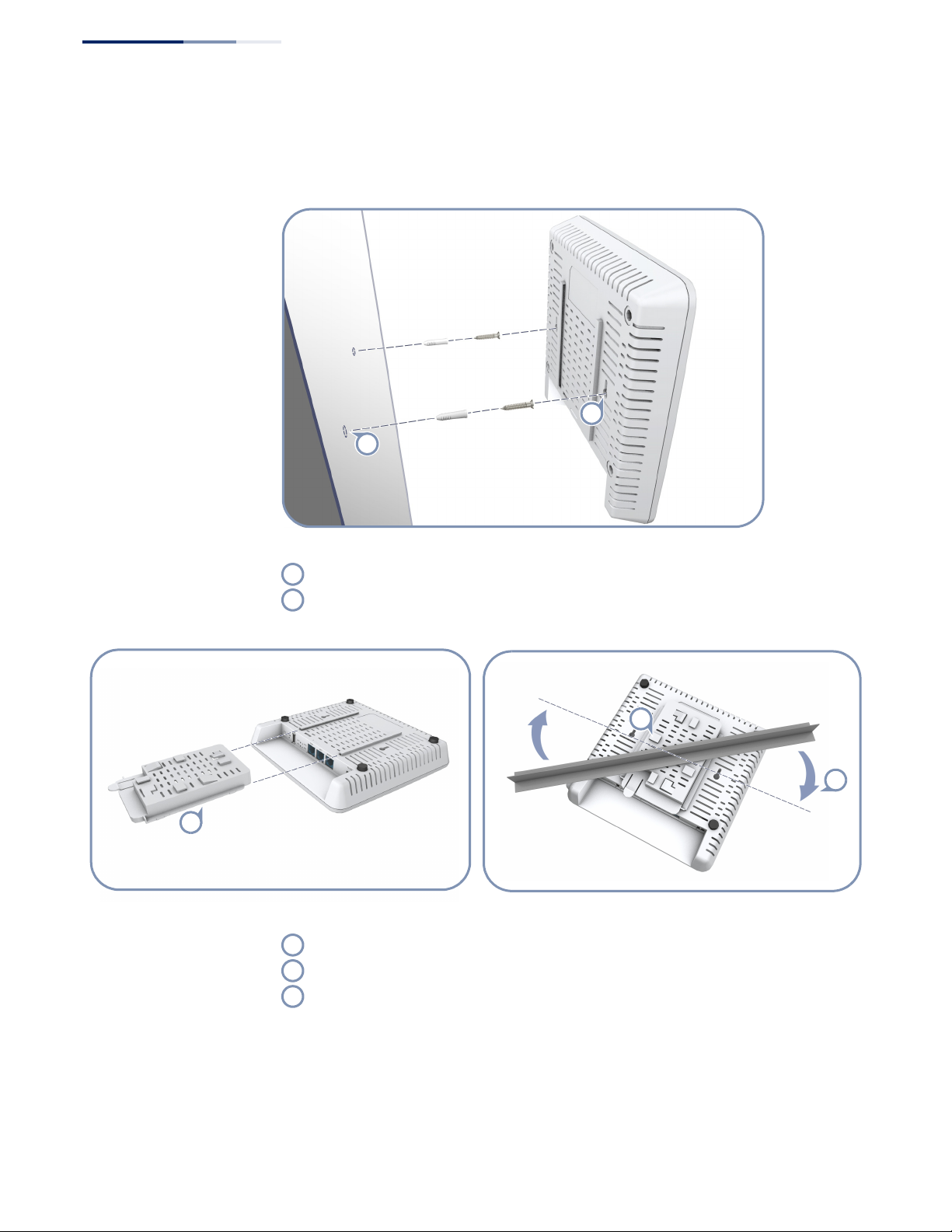
2. Mount the AP After planning your installation, mount the unit on a wall or suspended ceiling
T-rail.
.
Mounting on a Wall
Set two screws in the wall 116 mm (4.57 in.) apart.
Slide the AP’s wall mounting slots down onto the screws so that the unit is secure.
.
Mounting on a Ceiling T-rail
Attach the included ceiling-mount accessory to the base of the AP.
Position the AP’s ceiling-mount clip holders on either side of the T-rail.
Turn the AP until the two clips lock the AP to the T-rail.
– 2 –
Page 3

Quick Start Guide
1
1
1
2
1
2
3. Connect Cables Connect network cable to the WAN/PoE 1000BASE-T RJ-45 port for your network
connection. The WAN/PoE port connection can also provide PoE power to the unit.
(Optional) Connect a local LAN switch or computers to the LAN1 and LAN2
100BASE-TX RJ-45 ports.
Connect Category 5e or better cable to the WAN/PoE RJ-45 port.
4. Connect Power If you do not power the unit using PoE, connect the AC power adapter to the AP
and to an AC power source.
Connect the power adapter to the power socket on the AP.
Plug the power adapter into a nearby AC power source.
– 3 –
Page 4

Quick Start Guide
1
2
1
2
5. Verify AP Operation Verify basic AP operation by checking the system LEDs.
The WAN LED and any connected LAN port LEDs should light up green. The circular
LED on the top panel should light up green and blue to indicate 2.4 GHz and 5 GHz
radio operation respectively.
6. Connect to the Web
User Interface
WAN and LAN1/LAN2 Link/Activity LEDs
Radio LED — 2.4 GHz (green) and 5 GHz (blue)
The AP offers a user-friendly web-based management interface for the
configuration of all the unit’s features.
You can make initial configuration changes by connecting a PC directly to the AP’s
LAN port. The AP has a default management IP address of 192.168.2.1 and a subnet
mask of 255.255.255.0. You must set your PC IP address to be on the same subnet as
the AP (that is, the PC and AP addresses must both start 192.168.2.x).
Log in to the web interface using the default settings:
◆ Login Name — root
◆ Password — admin123
– 4 –
Page 5

Quick Start Guide
For more information on AP configuration using the web interface, refer to the
Management Guide, which is on the Edge-Core web site, www.edge-core.com.
– 5 –
Page 6

Quick Start Guide
Hardware Specifications
Item Specification
Chassis
Size (W x D x H) 200 x 200 x 36.5 mm (7.87 x 7.87 x 1.44 inch)
Weight 750 g (1.65 lb)
Temperature Operating: 0 °C to 40 °C (32 °F to 104 °F)
Humidity Operating: 5% to 95% (non-condensing)
Network Interfaces
Ports WAN/PoE RJ-45 Port: 1000BASE-T, PoE+ PD
2.4 GHz Radio IEEE 802.11b/g/n
5 GHz Radio IEEE 802.11a/ac/n
Storage: -20 °C to 70 °C (-4 °F to 158 °F)
LAN1 and LAN2 RJ-45 Ports: 100BASE-TX
Radio Frequencies 2412 ~ 2472 MHz
5745 ~ 5825 MHz (China)
5180 ~ 5320 MHz (ETSI)
5500 ~ 5700 MHz (ETSI)
Power Supply
PoE Input Power 48 VDC, 0.6 A
AC Power Adapter AC Input: 100 ~ 240 VAC
DC Output: 12 VDC, 2 A
Power Consumption 22.5 W maximum
Regulatory Compliances
Radio EN 300 328 V1.8.1:2012
EN 301 893 V1.7.1:2012
EN 301 489-1 V1.9.2 (2011-09)
EN 301 489-7 V1.3.1:2005
FCC Part 15C 15.247/15.207 (2.4-2.4835GHz, 5.725-5.850GHz)
FCC Part 15E 15.407 (5.150GHz-5.250GHz)
Emissions EN 55022 2010+AC:2011
EN 61000-3-2 2006+A1:2009+A2:2009
FCC Class B Part 15
Immunity EN 55024 : 2010
EN 61000-4-2 : 2009
Safety UL (CSA 22.2 No. 60950-1 & UL60950-1)
CB (IEC/EN60950-1)
– 6 –
 Loading...