

Page 1
Quick Start Guide
1
2
1
2
MetroLinq™ 2.5G Outdoor 60 GHz PTP/PTMP + 5 GHz
ML2.5-60-35 | ML2.5-60-19 | ML2.5-60-BF-18
Welcome to MetroLinq™
Interference-Free Gigabit Wireless
Unboxing
After opening the box, you will find…
◆
MetroLinq™ (ML2.5-60-35, ML2.5-60-19, or ML2.5-60-BF-18)
◆
PoE Power Supply
◆
Power Cable
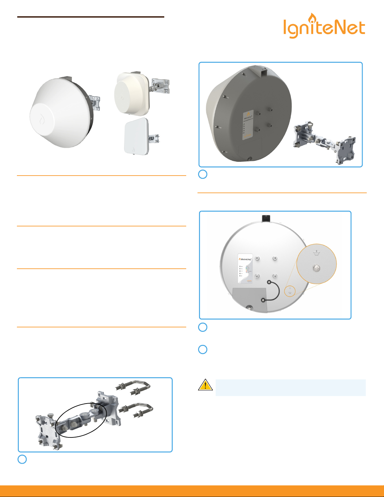
Install the Standard Bracket onto MetroLinq™ using four M8
bolts, lock washers, and flat washers.
Grounding
Tools/Items Required
◆
13 mm Socket Wrench
◆
Flat-Head Screwdriver
◆
Ethernet Cables
Options
◆
Standard Bracket ICC-BRACKET-STD
◆
Long Range Precision Bracket ICC-BRACKET-LR
◆
Alignment Scope ICC-SCOPE-9x50
For helpful training and user-case information, please go to
ignitenet.com/support
Assembly
The MetroLinq™ Standard Bracket and Long Range Precision Bracket
(both ordered separately) are designed for wall and pole mounting
(25 mm - 80 mm pole diameter). Choose what is best for your
location and select hardware accordingly.
Ensure the structure on which the unit is to be mounted is
properly grounded and in compliance with ETSI ETS 300
253.
Verify that there is a good electrical connection to a
grounding point (no paint or isolating surface treatment).
Use the included (M4) screw to attach a grounding wire (not
included) to the grounding point on the unit, and then to
ground.
Caution:
unless all supply connections have been disconnected.
The earth connection must not be removed
Ensure all four position-locking bolts on the Standard
Bracket are tight before installing.
www.ignitenet.com
– 1 –
MetroLinq 2.5G
E102017-CS 15020000xxxxA R01
Page 2
Power Up
1
2
3
2
1
4
A
2
3
B
12345
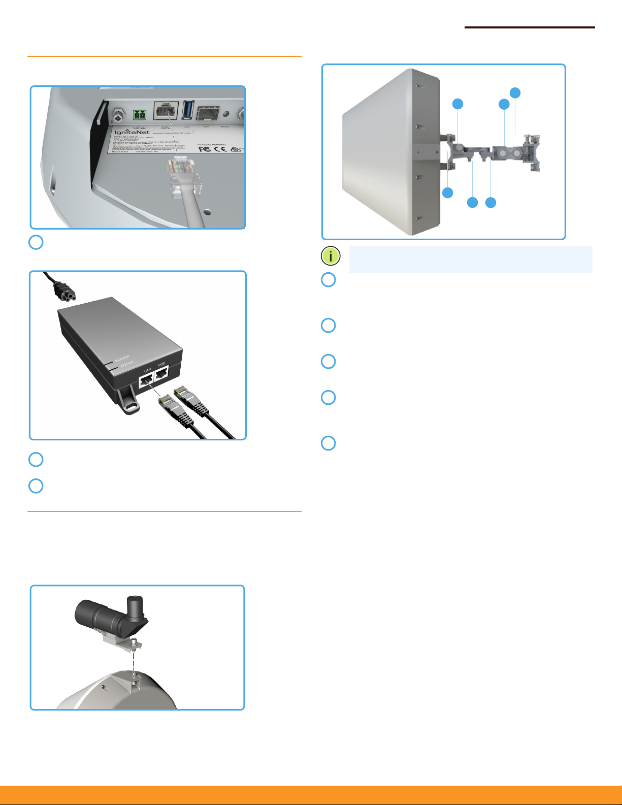
Connect an Ethernet cable from the MetroLinq™ ETH PoE IN
port to the PoE port on the power supply.
Connect Ethernet cable from the “LAN” port on the power
supply to your LAN device.
Connect the power cord to a nearby AC power source.
Quick Start Guide
Note:
Do not adjust bolts A and B without first loosening 1
and 4 respectively.
Loosen coarse adjustment bolts 2 and 3 and set initial
alignment. Don’t worry, you don’t have to be too accurate
yet. After you have set the coarse alignment, tighten bolts 2
and 3.
Loosen the horizontal fine-tune adjustment bolt 4. Use finetune bolt "B" to optimize the horizontal position. Re-tighten
bolt 4.
Loosen the vertical fine-tune adjustment bolt 1. Use finetune bolt "A" to optimize the vertical position. Re-tighten
bolt 1.
Initial alignment should be based on optical or visual
alignment. After you achieve this, repeat steps 2 and 3 while
watching the 60 GHz signal strength LED. Optimize position
to the LED indicator.
Ensure all bolts are fully tightened, remove the alignment
scope (if installed), and enjoy Gigabit interference-free
wireless.
Standard Bracket Alignment
IgniteNet strongly recommends using the ICC-SCOPE-9x50
Alignment Scope for alignment. To install, place the scope on top of
the MetroLinq™ housing and secure it with its thumb screw.
– 2 –
Page 3
Quick Start Guide
122
Software
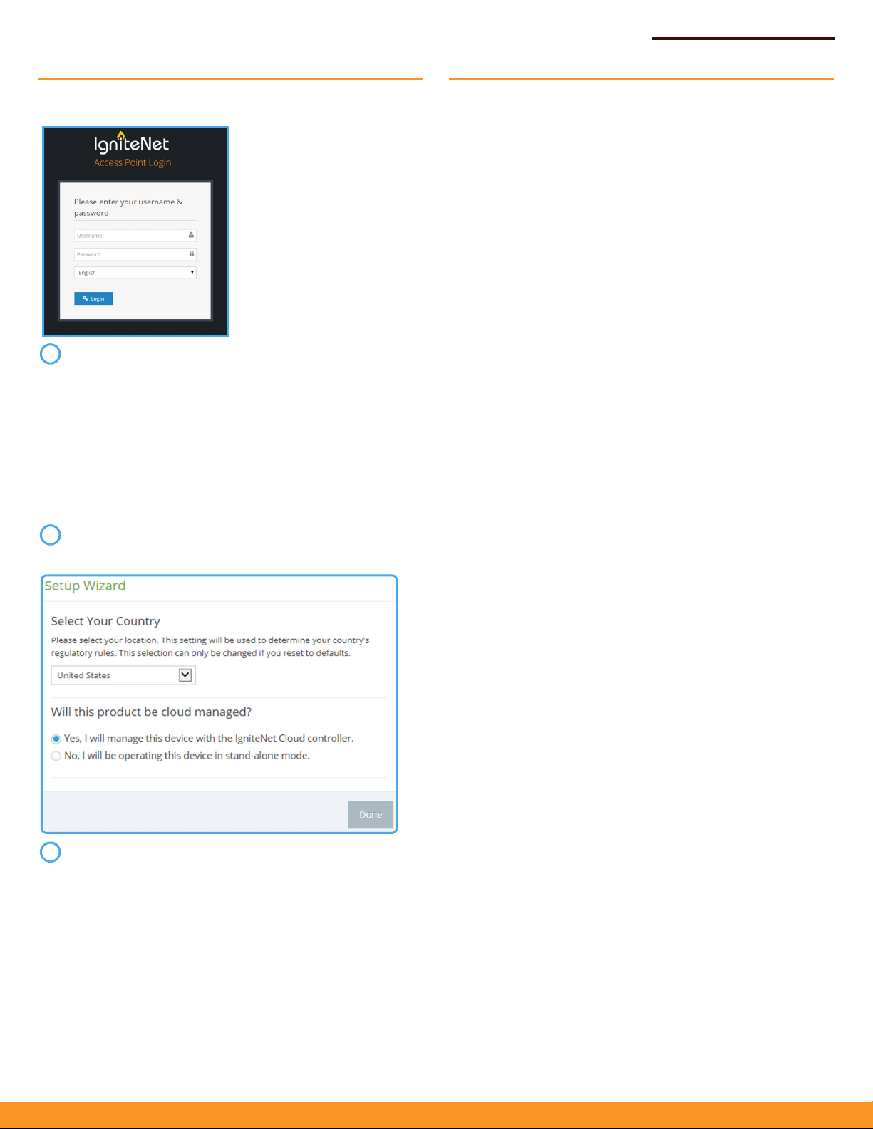
To configure your MetroLinq, connect your computer to the
device through the LAN port of the power supply or directly
to the ETH1 port on the device.
The default IP mode is DHCP client, so if the device obtains
an address from a DHCP server on the network, then use
that IP (you can use the Discovery Tool from the IgniteNet
support site to find the DHCP address). If the device does
not obtain a DHCP address, it reverts to the fallback IP of
192.168.1.20 and you can access it on that IP. Direct your
web browser to the correct IP and log in.
username: root
password: admin123
After you have logged in, follow the steps in the Setup
Wizard to configure the device for your network.
Safety and Regulatory Information
FCC Class B
This device complies with Part 15 of the FCC Rules. Operation is subject
to the following two conditions: (1) This device may not cause harmful
interference, and (2) this device must accept any interference received,
including interference that may cause undesired operation.
This equipment has been tested and found to comply with the limits for
a Class B digital device, pursuant to Part 15 of the FCC Rules. These limits
are designed to provide reasonable protection against harmful
interference in a residential installation. This equipment generates, uses
and can radiate radio frequency energy and, if not installed and used in
accordance with the instructions, may cause harmful interference to
radio communications. However, there is no guarantee that interference
will not occur in a particular installation. If this equipment does cause
harmful interference to radio or television reception, which can be
determined by turning the equipment off and on, the user is
encouraged to try to correct the interference by one of the following
measures:
◆ Reorient or relocate the receiving antenna
◆ Increase the separation between the equipment and receiver
◆ Connect the equipment into an outlet on a circuit different from
that to which the receiver is connected
◆ Consult the dealer or an experienced radio/TV technician for help
FCC Caution: Any changes or modifications not expressly approved by
the party responsible for compliance could void the user’s authority to
operate this equipment.
This transmitter must not be co-located or operating in conjunction with
any other antenna or transmitter.
The 5600-5650MHz band is disabled by software during manufacturing
and cannot be changed by the end user. This device meets all the other
requirements specified in Part 15E, Section 15.407 of the FCC Rules.
After you have logged in, follow the steps in the Setup
Wizard to configure the device for your network.
For more configuration details and training, please go to
ignitenet.com/support
IMPORTANT NOTE:
Radiation Exposure Statement:
This equipment complies with FCC radiation exposure limits set forth
for an uncontrolled environment. This equipment should be installed
and operated with minimum distance 20 cm between the radiator and
your body.
Professional installation is required.
Note: The country code selection is for non-US models only and is not
available on all US models. Per FCC regulation, all Wi-Fi products
marketed in the US must be fixed to US operation channels only.
Professional Installation Instructions
1. Installation personal
This product is designed for specific applications and needs to be
installed by a qualified person who has RF and related rules knowledge.
The general user shall not attempt to install or change the settings.
2. Installation location
The product shall be installed at a location where the radiating antenna
can be kept 20 cm from nearby persons in normal operation conditions
to meet regulatory RF exposure requirements.
– 3 –
Page 4

Quick Start Guide
3. External antenna
Use only the antennas that have been approved by the applicant. Nonapproved antenna(s) may produce unwanted spurious or excessive RF
transmitting power, which may lead to the violation of FCC/IC limits and
is prohibited.
4. Installation procedure
Please refer to user's manual for details.
5. Warning
Please carefully select the installation position and make sure that the
final output power does not exceed the limits set forcth in relevant rules.
Violation of the rules could lead to serious federal penalties.
Instructions d'installation professionnelle
1. Installation
Ce produit est destiné à un usage spécifique et doit être installé par un
personnel qualifié maîtrisant les radio-fréquences et les règles s'y
rapportant. L'installation et les réglages ne doivent pas être modifiés par
l'utilisateur final.
2. Emplacement d'installation
En usage normal, afin de respecter les exigences réglementaires
concernant l'exposition aux radio-fréquences, ce produit doit être
installé de façon à respecter une distance de 20 cm entre l'antenne
émettrice et les personnes.
3. Antenne externe
Utiliser uniquement les antennes approuvées par le fabricant.
L'utilisation d'autres antennes peut conduire à un niveau de
rayonnement essentiel ou non essentiel dépassant les niveaux limites
définis par FCC/IC, ce qui est interdit.
4. Procedure d'installation
Consulter le manuel d'utilisation.
5. Avertissement
Choisir avec soin la position d'installation et s'assurer que la puissance
de sortie ne depasse pas les limites en vigueur. La violation de cette
règle peut conduire à de sérieuses pénalites fédérales.
IC Statement
This device complies with Industry Canada’s licence-exempt RSSs.
Operation is subject to the following two conditions:
(1) This device may not cause interference; and
5G Antenna List:
Ant. Brand P/N Antenna Type Connector
cton 120G0000017
X
6
Dish N/A
Gain (dBi)
Band 1 Band 4
10.1
12.11 Ac
60G Antenna List:
Ant. Brand P/N Antenna Type Connector Gain (dBi)
1 Accton 120300000225X
Dish N/A
17.2
The maximum antenna gain permitted for devices in the band 57255850 MHz shall be such that the equipment still complies with the e.i.r.p.
limits specified for point-to-point and non-point-to-point operation as
appropriate.
Le gain maximal d’antenne permis (pour les dispositifs utilisant la bande
5725-5850 MHz) doit se conformer à la limite de p.i.r.e. spécifiée pour
l’exploitation point à point et non point à point, selon le cas.
IMPORTANT NOTE:
IC Radiation Exposure Statement:
This equipment complies with IC RSS-102 radiation exposure limits set
forth for an uncontrolled environment. This equipment should be
installed and operated with minimum distance 23 cm between the
radiator & your body.
Cet équipement est conforme aux limites d'exposition aux rayonnements IC
établies pour un environnement non contrôlé. Cet équipement doit être
installé et utilisé avec un minimum de 23 cm de distance entre la source de
rayonnement et votre corps.
CE Mark
CE Mark Declaration of Conformance for EMI and Safety (EEC)
This is a class B product. In a domestic environment, this product may
cause radio interference, in which case the user may be required to take
adequate measures.
National Restrictions
This device is intended for home and office use in all EU countries (and
other countries following the EU directive 1999/5/EC) without any
limitation except for the countries mentioned below:
(2) This device must accept any interference, including interference that
may cause undesired operation of the device.
Le présent appareil est conforme aux CNR d'Industrie Canada applicables
aux appareils radio exempts de licence. L'exploitation est autorisée aux deux
conditions suivantes : (1) l'appareil ne doit pas produire de brouillage, et (2)
l'utilisateur de l'appareil doit accepter tout brouillage radioélectrique subi,
même si le brouillage est susceptible d'en compromettre le fonctionnement.
This radio transmitter (IC: 3857A-ML2560) has been approved by
Industry Canada to operate with the antenna types listed below with the
maximum permissible gain indicated. Antenna types not included in this
list, having a gain greater than the maximum gain indicated for that
type, are strictly prohibited for use with this device.
Le présent émetteur radio (IC: 3857A-ML2560) a été approuvé par Industrie
Canada pour fonctionner avec les types d'antenne énumérés ci-dessous et
ayant un gain admissible maximal d'antenne. Les types d'antenne non
inclus dans cette liste, ou dont le gain est supérieur au gain maximal
indiqué, sont strictement interdits pour l'exploitation de l'émetteur.
Country Restriction Reason/Remark
Bulgaria None General authorization required for
outdoor use and public service
France Outdoor use limited
to 10 mW e.i.r.p.
within the band
2454-2483.5 MHz
Military Radiolocation use.
Refarming of the 2.4 GHz band has
been ongoing in recent years to
allow current relaxed regulation.
Full implementation planned 2012
italy None If used outside of own premises,
general authorization is required
Luxembourg None General authorization required for
network and service supply(not for
spectrum)
– 4 –
Page 5

Country Restriction Reason/Remark
Norway Implemented This subsection does not apply for
the geographical area within a
radius of 20 km from the centre of
Ny-Ålesund
Russian
None Only for indoor applications
Federat ion
Note:
Do not use the product outdoors in France.
Europe - EU Declaration of Conformity
This device complies with the essential requirements of the R&TTE
Directive 1999/5/EC. The following test methods have been applied in
order to prove presumption of conformity with the essential
requirements of the R&TTE Directive 1999/5/EC:
◆ EN 60950-1:2006+A11:2009+A1:2010+A12:2011+A2:2013
Safety of Information Technology Equipment.
◆ EN 300 328 V1.8.1: 2012
Electromagnetic compatibility and Radio spectrum Matters (ERM);
Wideband transmission systems; Data transmission equipment
operating in the 2,4 GHz ISM band and using wide band modulation
techniques; Harmonized EN covering essential requirements under
article 3.2 of the R&TTE Directive.
◆ EN 301 489-1 V1.9.2 (2011-09)
EN 301 489-7 V1.3.1/ 2005
Electromagnetic compatibility and Radio spectrum Matters (ERM);
Electromagnetic Compatibility (EMC) standard for radio equipment
and services; Part 17: Specific conditions for 2.4 GHz wideband
transmission systems and 5 GHz high performance RLAN
equipment.
◆ EN 55022 2010 + AC: 2011
Limits and methods of measurement of radio disturbance
characteristics of information technology equipment.
◆ EN 55024: 2010
Information technology equipment immunity characteristics limits
and methods of measurement.
◆ EN 62311: 2008
Assessment of electronic and electrical equipment related to
human exposure restrictions for electromagnetic fields (0 Hz - 300
GHz).
This device is a 2.4 GHz wideband transmission system (transceiver),
intended for use in all EU member states and EFTA countries, except in
France and Italy where restrictive use applies.
In Italy the end-user should apply for a license at the national spectrum
authorities in order to obtain authorization to use the device for setting
up outdoor radio links and/or for supplying public access to
telecommunications and/or network services.
This device may not be used for setting up outdoor radio links in France
and in some areas the RF output power may be limited to 10 mW EIRP in
the frequency range of 2454 - 2483.5 MHz. For detailed information the
end-user should contact the national spectrum authority in France.
Quick Start Guide
The Declaration of Conformity (DoC) can be obtained from
www.ignitenet.com -> support -> download -> declarations &
certifications.
This equipment may be operated in:
Bulgarian
Български
Czech
Česky
Danish
Dansk
Dutch
Nederlands
English Hereby, IgniteNet, declares that this Radio LAN device is in
Estonian
Eesti
Finnish
Suomi
French
Français
German
Deutsch
Greek
Ελληνική
Hungarian
Magyar
Italian
Italiano
С настоящето, IgniteNet декларира, че това безжично
устройство е в съответствие със съществените
изисквания и другите приложими разпоредби на
Директива 1999/5/EC.
IgniteNet tímto prohlašuje, že tento Radio LAN device je ve
shodě se základními požadavky a dalšími příslušnými
ustanoveními směrnice 1999/5/ES.
Undertegnede IgniteNet erklærer herved, at følgende udstyr
Radio LAN device overholder de væsentlige krav og øvrige
relevante krav i direktiv 1999/5/EF
Hierbij verklaart IgniteNet dat het toestel Radio LAN device in
overeenstemming is met de essentiële eisen en de andere
relevante bepalingen van richtlijn 1999/5/EG
Bij deze IgniteNet dat deze Radio LAN device voldoet aan de
essentiële eisen en aan de overige relevante bepalingen van
Richtlijn 1999/5/EC.
compliance with the essential requirements and other
relevant provisions of Directive 1999/5/EC.
Käesolevaga kinnitab IgniteNet seadme Radio LAN device
vastavust direktiivi 1999/5/EÜ põhinõuetele ja nimetatud
direktiivist tulenevatele teistele asjakohastele sätetele.
Valmistaja IgniteNet vakuuttaa täten että Radio LAN device
tyyppinen laite on direktiivin 1999/5/EY oleellisten
vaatimusten ja sitä koskevien direktiivin muiden ehtojen
mukainen.
Par la présente IgniteNet déclare que l'appareil Radio LAN
device est conforme aux exigences essentielles et aux
autres dispositions pertinentes de la directive 1999/5/CE.
Hiermit erklärt IgniteNet, dass sich dieser/diese/dieses Radio
LAN device in Übereinstimmung mit den grundlegenden
Anforderungen und den anderen relevanten Vorschriften der
Richtlinie 1999/5/EG befindet. (BMWi)
Hiermit erklärt IgniteNet die Übereinstimmung des Gerätes
Radio LAN device mit den grundlegenden Anforderungen
und den anderen relevanten Festlegungen der Richtlinie
1999/5/EG. (Wien)
με την παρουσα IgniteNet δηλωνει οτι radio LAN device
συμμορφωνεται προσ τισ ουσιωδεισ απαιτησεισ και τισ
λοιπεσ σχετικεσ διαταξεισ τησ οδηγιασ 1999/5/εκ.
Alulírott, IgniteNet nyilatkozom, hogy a Radio LAN device
megfelel a vonatkozó alapvetõ követelményeknek és az
1999/5/EC irányelv egyéb elõírásainak.
Con la presente IgniteNet dichiara che questo Radio LAN
device è conforme ai requisiti essenziali ed alle altre
disposizioni pertinenti stabilite dalla direttiva 1999/5/CE.
– 5 –
Page 6

Quick Start Guide
Latvian
Latviski
Lithuanian
Lietuvių
Maltese
Malti
Polish
Polski
Portuguese
Português
Romanian
Romană
Slovak
Slovensky
Slovenian
Slovensko
Spanish
Español
Swedish
Svenska
Turkish
Turk
Ar šo IgniteNet deklarē, ka Radio LAN device atbilst
Direktīvas 1999/5/EK būtiskajām prasībām un citiem ar to
saistītajiem noteikumiem.
Šiuo IgniteNet deklaruoja, kad šis Radio LAN device atitinka
esminius reikalavimus ir kitas 1999/5/EB Direktyvos
nuostatas.
Hawnhekk, IgniteNet, jiddikjara li dan Radio LAN device
jikkonforma mal-ħtiġijiet essenzjali u ma provvedimenti
oħrajn relevanti li hemm fid-Dirrettiva 1999/5/EC.
Niniejszym IgniteNet oświadcza, że Radio LAN device jest
zgodny z zasadniczymi wymogami oraz pozostałymi
stosownymi postanowieniami Dyrektywy 1999/5/EC.
IgniteNet declara que este Radio LAN device está conforme
com os requisitos essenciais e outras disposições da
Directiva 1999/5/CE.
IgniteNet declară că acest dispozitiv fără fir respectă
cerinţele esenţiale precum şi alte dispoziţii relevante ale
Directivei 1999/5/EC.
IgniteNet týmto vyhlasuje, že Radio LAN device spĺňa
základné požiadavky a všetky príslušné ustanovenia
Smernice 1999/5/ES.
IgniteNet izjavlja, da je ta radio LAN device v skladu z
bistvenimi zahtevami in ostalimi relevantnimi določili direktive
1999/5/ES.
Por medio de la presente IgniteNet declara que el Radio LAN
device cumple con los requisitos esenciales y cualesquiera
otras disposiciones aplicables o exigibles de la Directiva
1999/5/CE
Härmed intygar IgniteNet att denna Radio LAN device står I
överensstämmelse med de väsentliga egenskapskrav och
övriga relevanta bestämmelser som framgår av direktiv
1999/5/EG.
IgniteNet bu kablosuz cihazın temel gereksinimleri ve 1999/
5/EC yonergesindeki ilgili koşulları karşıladığını beyan eder.
Warnings and Cautionary Messages
Warning:
parts.
Warning:
out by qualified personnel only.
Warning:
connect the field ground lead on the tri-pole power plug to a
valid earth ground line to prevent electrical hazards.
Caution:
measures to prevent electrostatic discharge when handling this
equipment.
Caution:
port. This may damage this device.
Caution:
that conform to FCC standards.
This product does not contain any serviceable user
Installation and removal of the unit must be carried
When connecting this device to a power outlet,
Wear an anti-static wrist strap or take other suitable
Do not plug a phone jack connector in the RJ-45
Use only twisted-pair cables with RJ-45 connectors
NCC Statement (Taiwan)
低功率電波輻射性電機管理辦法
第十二條 經型式認證合格之低功率射頻電機,非經許可,公司、商號或
使用者均不得擅自變更頻率、加大功率或變更原設計之特性及功能。
第十四條 低功率射頻電機之使用不得影響飛航安全及干擾合法通信;經
發現有干擾現象時,應立即停用,並改善至無干擾時方得繼續使用。前
項合法通信,指依電信法規定作業之無線電通信。低功率射頻電機須忍
受合法通信或工業、科學及醫療用電波輻射性電機設備之干擾。
電磁波曝露量 MPE 標準值 1mW/cm²,本產品使用時建議應距離人體
58 cm。
TELEC Statement (Japan)
5.2/5.3GHz帯の無線LAN 製品は法令により屋外では使用できません。
屋內のみでご使用ください。
All wireless LAN products in the 5.2/5.3GHz band cannot be used
outdoors. Use the product only indoors.
– 6 –
Page 7

Hardware Specifications
Chassis
Size (L x W x H:)
Weight
Temperature
Humidity
Network Interfaces
Ports ETH RJ-45 Port: 1000BASE-T, passive PoE
60 GHz Radio IEEE 802.11ad
5 GHz Radio IEEE 802.11ac
Radio Frequencies 5150 ~ 5250 MHz (FCC)
Power Supply
Passive PoE 48 VDC, maximum 0.5 A
Power Consumption 24 W maximum
Regulatory Compliances
Radio EN 300 328 V1.8.1:2012
Emissions EN 55022 2010+AC:2011
Immunity EN 55024 : 2010
ML2.5-60-35:
350 x 350 x 200 mm (13.78 x 13.78 x 7.87 in.)
ML2.5-60-19:
190 x 190 x 120 mm (7.48 x 7.48 x 4.72 in.)
ML2.5-60-BF-18:
190 x 190 x 60 mm (7.48 x 7.48 x 2.36 in.)
ML2.5-60-35: 3.5 kg (7.72 lb)
ML2.5-60-19: 2 kg (4.41 lb)
ML2.5-60-BF-18: 2 kg (4.41 lb) with mount
Operating: -30 °C to 55 °C (-22 °F to 131 °F) / ML2.5-60-BF-18: -40 °C to 70 °C (-40 °F to 158 °F)
Storage: -40 °C to 70 °C (-40 °F to 158 °F)
Operating: 10% to 90% (non-condensing)
SFP Port: 1000BASE-X
5725 ~ 5850 MHz (FCC)
5745 ~ 5825 MHz (China)
5180 ~ 5320 MHz (ETSI)
5500 ~ 5700 MHz (ETSI)
58.32 ~ 64.80 GHz
EN 301 893 V1.7.1:2012
EN 301 489-1 V1.9.2 (2011-09)
EN 301 489-17 V2.2.1:2012
FCC Part 15C 15.247/15.207 (2.4-2.4835GHz)
FCC Part 15E 15.407 (5.150GHz-5.250GHz,
5.725-5.850GHz)
EN 61000-3-2 2006+A1:2009+A2:2009
FCC Class B Part 15
EN 61000-4-2 : 2009
Quick Start Guide
– 7 –
Page 8

IgniteNet Inc.
20 Mason, Irvine, CA, 92618 USA
antenna is normally mounted on a mast and is vertically polarized.
This
Warning:
Please carefully select the installation position and make sure that the final output power does not exceed the limit set force in relevant
rules. The violation of the rule could lead to serious federal penalty.
The maximum e.i.r.p. at any elevation angle above 30 degrees as measured from the horizon must not exceed 125 mW (21 dBm).
The antenna must be installed completely perpendicular to the horizon.
 Loading...