

Page 1
Quick Start Guide
2
1
1
2
2
1
1
2
2
1
2
Gigabit Ethernet to Coax bridge
GLinq GL-O-1GE-1C
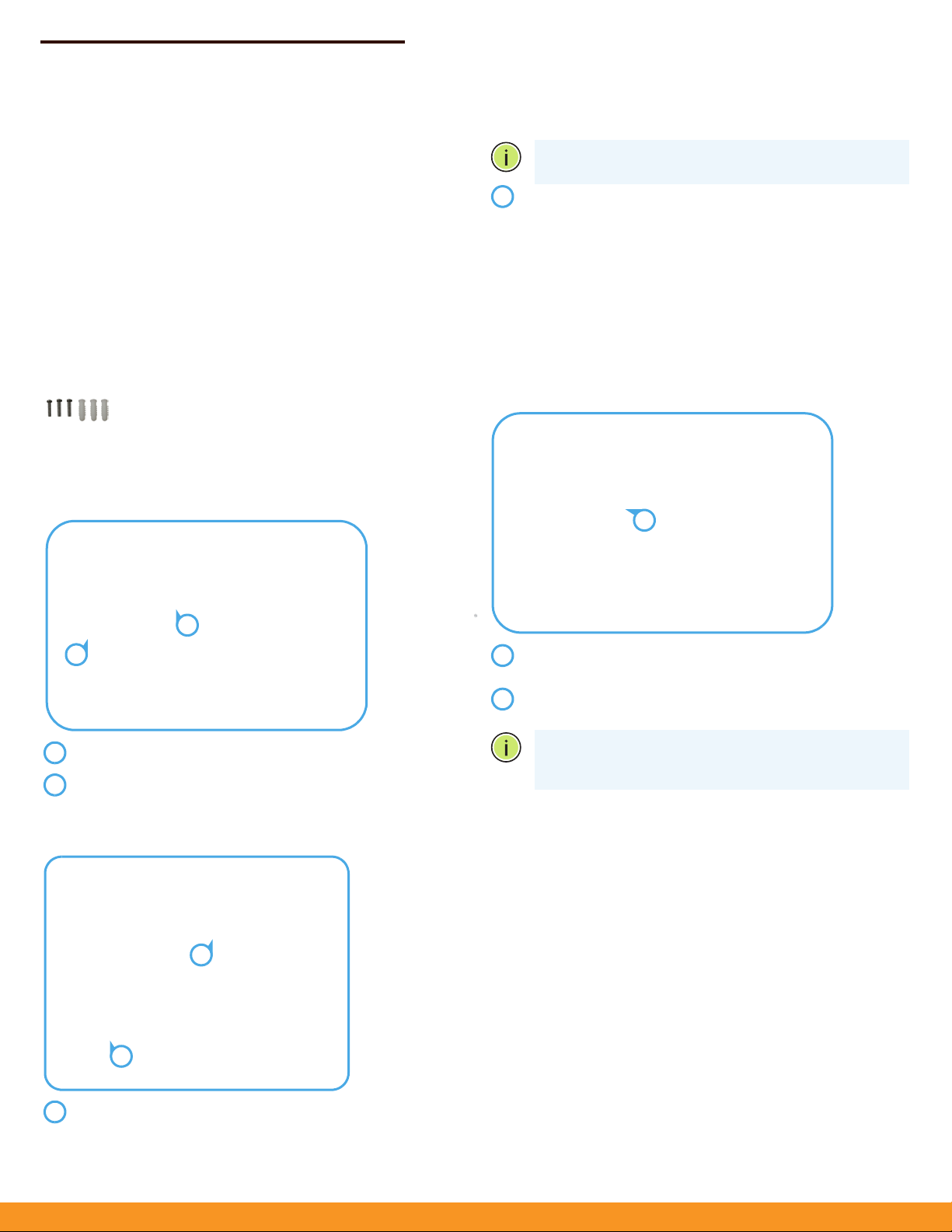
1. Unpack and Check Contents
or a wood wall, drilling holes and using wall anchors
F
Note:
is not required.
GL-O-1GE-1
Outdoor
12 VDC Power Supply
QSG will be posted to the Web
Wall Mounting Screw Kit
C-XX
GE to G.hn Coax Bridge AP
2. Mount the Bridge AP
a. M
ounting on a Pole
*
Mount the unit on the wall and secure it in place using the
included three M4 x20 tapping screws.
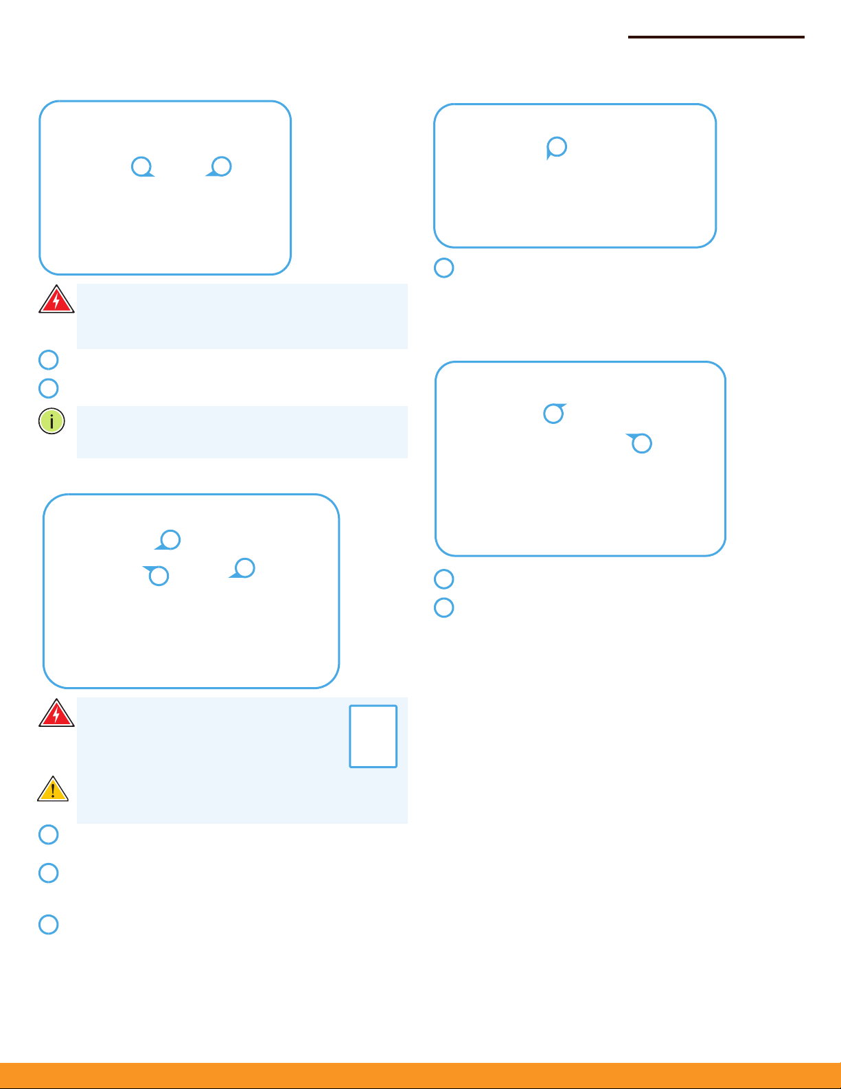
3. Connect Power
The bridge AP can receive power from one of three different power
sources:
◆
The supplied DC power adapter to the DC power jack.
◆
An external DC power source to its DC In/Out terminal block
◆
Power over Coaxial cable (PoC) to the F-type coaxial connector
(from another Ignite GLinq only)
a. DC Power Jack
Place the unit against the pole (diameter 20-200 mm).
Use up to 12 mm (1/2 in) strapping to secure the unit to the
pole.
b. Mounting on a Wall
In the required location, mark and drill three holes in the wall
for M4 wall anchors.
Plug the DC power supply into a suitable power mains
outlet.
Insert the DC power supply DIN connector into the bridge
APs DC power jack.
Note:
When po
switch is set to ON, the F-type coaxial connector functions as
a 12 VDC PoC power source.
wer is supplied to the DC jack and the DC
www.ignitenet.com
– 1 –
Page 2
Quick Start Guide
2
1
1
2
2
3
1
123
1
1
1
2
1
2
b. DC Power Block
Warning:
Before wiring the DC In/Out or connecting
power to the device, ensure that power to the feed lines is
turned off at the supply circuit breaker or disconnected from
the power bus.
Connect the DC power feed wire to the DC In/Out “+” pin.
Connect the ground/return wire to the DC In/Out “-” pin.
Note:
When power is supplied to the DC In/Out and the DC
switch is set to ON, the F-type coaxial connector functions as
a 12-54 VDC PoC power source.
c. PoC Power
4. Verify Bridge AP Operation
Verify basic switch operation by checking the system LEDs.
When operating normally, the Power LED should be on
green, and the WiFi, Eth and G.hn LEDs should be on or
blinking green.
5. Connect an Ethernet Cable
Warning:
Before connecting a coaxial cable
with power to the bridge AP, ensure the PoC DC
switches are in the OFF position on both the PoC
source bridge AP and the PoC receive bridge AP.
Caution:
To prevent damage when physically connecting a
coaxial cable, follow the instructions in step: 6. Connect a
Coaxial Cable
Using the DC jack, connect power to the bridge AP that is to
supply coaxial cable power.
On both the power source and receive bridge APs connect a
coaxial cable. Refer to step: 6. Connect a Coaxial Cable of this
guide on how to connect coaxial cable connectors.
On the bridge AP that is to supply power, slide the PoC DC
switch to the ON position.
Connect Category 5e or better cable to the RJ-45 port.
As the connection is made, check the Ethernet port status
LED to be sure the link is valid:
◆
On Green — Port has a valid link.
◆
Blinking Green — Indicates network activity.
– 2 –
Page 3

Quick Start Guide
1
2
1
2
1
2
3
4
1
2
3
4
Log in to the web interface
using the default settings:
◆
Login Name — root
◆
Password — admin123
6. Connect a Coaxial Cable
Caution:
on the GLinq is overtightened. Do not tighten a connector
more than the maximum torque rating of
Note:
cable connectors to connect coaxial cable between the
bridge APs.
Note:
connectors. Always use standard threaded male Fconnectors.
Screw a male coaxial cable connector onto the bridge AP Ftype coaxial connector until it is finger tight. If you are using
a specialized torque wrench, tighten the connector to the
maximum specified torque of:
◆
Damage may occur if an F-type cable connector
168 N-cm (16 lb-in).
Use only threaded male F-type compression coaxial
It is NOT recommended to use Flex F or push-on
168 N-cm or 16 lb-in
Ethernet –
◆
plugged wire (on)
◆
unplugged wire (off)
◆
link activity (blinking)
G.hn –
◆
coaxial cable connected (on)
◆
coaxial cable disconnected (off)
◆
link activity (blinking)
Note:
To reset the Bridge AP to factory default settings,
press and hold down the AP’s Reset button for 5 seconds.
A quick press of the Reset button reboots the AP.
8. Complete the Device Configuration
a. Manage the AP with the IgniteNet Cloud Controller
Go to https://cloud.ignitenet.com to register your AP. Log in and
select Devices from the menu. Click Add Device and enter the AP
serial number and MAC address to register the AP with your cloud
network. (The serial number and MAC address can be found on the
product packaging or label.)
b. Manage the AP in Stand-Alone Mode (Optional)
To access the web interface, connect a PC directly to the AP’s Eth
RJ-45 port. In a web browser, enter the AP’s default management IP
address of 192.168.1.20 to access the web login page.
As the connection is made, check the G.hn port status LED to
be sure the link is valid:
◆
On Green — Port has a valid link.
◆
Blinking Green — Indicates network activity.
7.Verify AP Operation
Power LED, cloud status, gateway status –
◆
power connected (on)
◆
no power connected (off)
Wifi –
◆
radio enabled (on)
◆
radio disabled (off)
◆
link activity (blinking)
If you select to manage the AP in stand-alone mode, use the web
interface to manually make your configuration changes.
For more information on AP configuration in stand-alone mode,
refer to the HeliOS User Manual, which can be downloaded from:
https://support.ignitenet.com
Note:
To reset the Bridge AP to factory default settings,
press and hold down the AP’s Reset button for 5 seconds.
A quick press of the Reset button reboots the AP.
– 3 –
Page 4

Safety and Regulatory Information
FCC Class B
This equipment has been tested and found to comply with the limits for
20
a Class B digital device, pursuant to Part 15 of the FCC Rules. These limits
are designed to provide reasonable protection against harmful
interference in a residential installation. This equipment generates, uses
and can radiate radio frequency energy and, if not installed and used in
accordance with the instructions, may cause harmful interference to
radio communications. However, there is no guarantee that interference
will not occur in a particular installation. If this equipment does cause
harmful interference to radio or television reception, which can be
determined by turning the equipment off and on, the user is
encouraged to try to correct the interference by one of the following
measures:
◆
Reorient or relocate the receiving antenna
◆
Increase the separation between the equipment and receiver
◆
Connect the equipment into an outlet on a circuit different from
that to which the receiver is connected
◆
Consult the dealer or an experienced radio/TV technician for help
FCC Caution: Any changes or modifications not expressly approved by
the party responsible for compliance could void the user’s authority to
operate this equipment.
This device complies with Part 15 of the FCC Rules. Operation is subject
to the following two conditions: (1) This device may not cause harmful
interference, and (2) this device must accept any interference received,
including interference that may cause undesired operation.
For product available in the USA/Canada market, only channel 1–11 can
be operated. Selection of other channels is not possible.
Quick Start Guide
IMPORTANT NOTE:
FCC Radiation Exposure Statement:
This equipment complies with FCC radiation exposure limits set forth for
an uncontrolled environment. This equipment should be installed and
operated with minimum distance
body.
cm between the radiator and your
Industry Canada
This device complies with Industry Canada license-exempt RSS
standard(s). Operation is subject to the following two conditions: (1) this
device may not cause interference, and (2) this device must accept any
interference, including interference that may cause undesired operation
of the device.
Le présent appareil est conforme aux CNR d'Industrie Canada
applicables aux appareils radio exempts de licence. L'exploitation est
autorisée aux deux conditions suivantes : (1) l'appareil ne doit pas
produire de brouillage, et (2) l'utilisateur de l'appareil doit accepter tout
brouillage radioélectrique subi, même si le brouillage est susceptible
d'en compromettre le fonctionnement.
For product available in the USA/Canada market, only channel 1~11 can
be operated. Selection of other channels is not possible.
Pour les produits disponibles aux États-Unis / Canada du marché, seul le
canal 1 à 11 peuvent être exploités. Sélection d'autres canaux n'est pas
possible.
IC Radiation Exposure Statement:
This equipment complies with ICRSS-102 radiation exposure limits
setforth for an uncontrolled environment. This equipment should
beinstalled and operated with minimum distance 20 cm between
theradiator and your body.
Cet équipement est conforme aux limites
d'exposition
auxrayonnements IC établies pour un environnement
non contrôlé. Cetéquipement doit être installé et utilisé
avec un minimum de 20 cm de
distance entre la source de rayonnement et votre corps.
– 4 –
Page 5
CE Statement
This equipment complies with EU radiation exposure limits set forth for
an uncontrolled environment. This equipment should be installed and
operated with minimum distance 20 cm between the radiator and your
body.
All operational modes:
2.4 GHz: 802.11b, 802.11g, 802.11n (HT20), 802.11n (HT40)
The frequency and maximum transmitted power limit in EU are listed as
below:
2412-2472 MHz: 20 dBm
Quick S
tart Guide
NCC Statement (Taiwan)
低功率電波輻射性電機管理辦法
第十二條 經型式認證合格之低功率射頻電機,非經許可,公司、商號或
使用者均不得擅自變更頻率、加大功率或變更原設計之特性及功能。
第十四條 低功率射頻電機之使用不得影響飛航安全及干擾合法通信;經
發現有干擾現象時,應立即停用,並改善至無干擾時方得繼續使用。前
項合法通信,指依電信法規定作業之無線電通信。低功率射頻電機須忍
受合法通信或工業、科學及醫療用電波輻射性電機設備之干擾。
Warnings and Cautionary Messages
Wa
rning:
parts.
Wa
out by qualified personnel only.
Wa
amperes of DC current if power is supplied to the unit and its DC
switch is in the ON position.
Wa
GLinq, you must ensure that all connected devices are capable
of sustaining a DC voltage applied to their coaxial input without
damage.
This product does not contain any serviceable user
rning:
Installation and removal of the unit must be carried
rning:
The F-type Coaxial Connector can conduct up to 2.5
If applying DC voltage to a coaxial cable using the
rning:
CZCYCHBGBEAT
FIESELEEDKDE
ITISIEHUHRFR
NLMTLVLULTLI
SISEROPTPLNO
UKTRSK
Europe - EU Declaration of Conformity
Hereby, IgniteNet Inc. declares that the radio equipment type: Outdoor
Gigabit Ethernet to G.hn Coax. Bridge AP w/PoC GL-O-1GE-1C-XX is
in compliance with Directive 2014/53/EU.
The full text of the EU declaration of conformity is available at the
following Internet address:
www.ignitenet.com -> support.
ution:
Ca
measures to prevent electrostatic discharge when handling this
equipment.
Caution:
port. This may damage this device.
Ca
that conform to FCC standards.
Wear an anti-static wrist strap or take other suitable
Do not plug a phone jack connector in the RJ-45
Use only twisted-pair cables with RJ-45 connectors
ution:
– 5 –
Page 6

Quick S
tart Guide
H
ardware Specifications
assis
Ch
Network Ports
Waterproof/
Dustproof
Power
Coaxial Cable Input
Power
Maximum Coaxial
Cable Output
Current
Power Consumption 6.5 W maximum
185 x 119 x 44 mm (7.28 x 4.69 x 1.73 in)Size (WxDxH)
450 g (0.99 lb)Weight
Operating: -40° C to 70° C (-40° F to 158° F)Temperature
S
Operating: 5% to 90% (non-condensing)Humidity
◆
◆
IP55
Power, Wireless 2.4 GHz, Ethernet, G.hnStatus LEDs
12 – 54 VDC, 1.0 ADC Input Power
12 VDC, 1.0 A
2.5 A
torage: -40° C to 70° C (-40° F to 158° F)
1000BASE-T RJ-45 PoE port
One
Gbps G.hn F-type Coaxial
One 2
Connector
Regulatory Compliance
Radio Frequencies 2412–2472 (FCC, IC, CE, AU, MIC, )
Immunity
Man
ufacturer Accton Technology Corporation
EN 55024:2010
IEC 61000-4-2/3/4/5/6/8/11
1, Creation 3rd Rd., Hsinchu Science Park,
Hsinchu 30077,
Taiwan, R.O.C
Standards
Ethernet
Wireless
G.hn Coax.
IEEE 802.3ab 1000BASE-T
IEEE 802.11b/g/n 2.4 GHz with 2x2 MIMO
ITU-T G.hn G.9960, G9961 bandplan: 25 MHz,
50 MHz, 100 MHz, 200 MHz (max. 2 Gbps)
– 6 –
E
102018-KS-R01
 Loading...