

Page 1
APPLICATION
The V4046C and V8046C Magnetic Valves provide on-off
control of gas flow in supply line.
V4046C, V8046C
Magnetic Valves
PRODUCT DATA
FEATURES
• Normally closed valves which open immediately when
energized.
• V4046C is for line voltage applications; V8046C is for
24 Vac applications.
• Provides on-off control of manufactured, Liquefied
Petroleum (LP), and natural gases with high sulfur
content.
• Used with pilot burners in industrial applications.
• All models close in one second (maximum) on power
failure.
• Heavily loaded spring plunger maintains valve seating
when the coil is de-energized, permitting the valve to
be mounted in any position.
• Valve may be pipe-mounted or mounted on bracket
support furnished by installer.
• Powerhead assembly can be rotated 360 angular
degrees.
• Solenoid coil is field-replaceable without removing the
valve body from the piping connection.
® U.S. Registered Trademark
Copyright © 2002 Honeywell • All Rights Reserved
Contents
Application ........................................................................ 1
Features ........................................................................... 1
Specifications ................................................................... 2
Ordering Information ........................................................ 2
Installation ........................................................................ 4
Wiring ............................................................................... 5
Checkout and Service ...................................................... 5
66-2008-3
Page 2
V4046C, V8046C MAGNETIC VALVES
SPECIFICATIONS
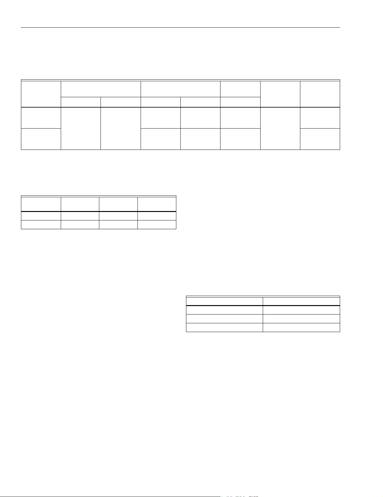
Models: See Table 1.
Table 1. Model Specifications.
Pressure Rating
Model
V4046C 10 69 20
V8046C 20
a
1/2 psi in AGA rating.
b
See body sizes, Fig. 2. 55 cfh (1.56 cmh) is for large body valve with 1/4-18 NPT threads; 67 cfh (1.90 cmh) is for large body
valve with 3/8-18 NPT threads.
c
Natural gas, 1000 btu/cu ft measured at one inch pressure drop, 0.64 specific gravity. See Gas Capacity Conversion Factors.
a
55
67
55
67
Gas Flow
b
m/hr btuh
0.57
1.56
1.90
0.57
1.56
1.90
Gas Heat
Capacitya
20,000
55,000
67,700
20,000
55,000
67,700
c
Operation
Energized
Opens
Immediately
Vol tag e s
(60 Hz)psi kPa cfh
120
208
24
Table 2. Coil VA Ratings.
24 Vac,
Model
V4046C — 13.8 13.7
V8046C 14.1 — —
Types of Gas: Suitable for all domestic gases including high
sulfur content LP gas.
Valve Material: Aluminum.
Valve Pattern: Straight-through.
Pipe Size: See Fig. 1.
Valve Action on Power Failure: All models close in one sec-
ond maximum.
Mounting:
Can be mounted in any position. Mounts directly in pipe line or
on a support bracket. See Fig. 2 for tapped holes provided
in bottom of valve body. Conduit outlet on powerhead can
be rotated through 360 degrees with respect to valve body.
60 Hz
120 Vac, 60 Hz208 Vac, 60
Hz
Wiring Connection: Two 36-in. (915 mm) leadwires; 1/2 in.
conduit bushing.
Ambient Temperature Range: -40°F to +125°F (-40°C to
+54°C).
Approvals:
Underwriters Laboratories, Inc. Listed: File NO. MH1639, V3,
S3; Guide No. YIOZ; V4046C, V8046C for gas.
Factory Mutual Listed: V4046C, V8046C for gas.
CSA 158158-250000605.8, Guide Numbers C3371-03, 83.
(60 Hz models only).
Replacement Parts: Coil assemblies include coil, leadwire,
insulator and bobbin. See Table 3.
Table 3. Coil Assemblies for V4046C, V8046C Valves.
Part Number Used On
116671A V4046C; 120 Vac, 60 Hz
116782A V4046C; 208 Vac, 60 Hz
11668A V8046C; 24 Vac, 60 Hz
ORDERING INFORMATION
When purchasing replacement and modernization products from your TRADELINE® wholesaler or distributor, refer to the
TRADELINE® Catalog or price sheets for complete ordering number.
If you have additional questions, need further information, or would like to comment on our products or services, please write or
phone:
1. Your local Home and Building Control Sales Office (check white pages of your phone directory).
2. Home and Building Control Customer Relations
Honeywell, 1885 Douglas Drive North
Minneapolis, Minnesota 55422-4386
In Canada—Honeywell Limited/Honeywell Limitée, 35 Dynamic Drive, Scarborough, Ontario M1V 4Z9.
International Sales and Service Offices in all principal cities of the world. Manufacturing in Australia, Canada, Finland, France,
Germany, Japan, Mexico, Netherlands, Spain, Taiwan, United Kingdom, U.S.A.
66-2008—3 2
Page 3
V4046C, V8046C MAGNETIC VALVES
6.0
0
B
1.
Gas Valve Sizing
1. Check the burner nameplate for:
a. the type of gas used, and
b. the gas flow capacity. The capacity will be listed in
British thermal units per hour(Btuh) or in cubic feet
per hour (cfh).
2. Contact the local gas utility for information regarding:
a. the specific gravity (sp gr) and
b. the Btu per cubic foot (Btucf) for the type of gas
used.
3. Find the capacity in cfh. If the capacity is listed in Btu,
convert to cfh using the following formula:
Capacity in cfh = Btuh (burner nameplate)
Btu/cu ft (gas utility)
4. For gases with specific gravity other than 0.64, multiply
the burner cfh using the proper conversion factor in
Table 4.
5.0
4.0
3.0
2.5
2.0
Table 4. Gas Conversion Factors.
Type of Gas sp gr (average) Multiply cfh by
Manufactured 0.60 0.968
Mixed 0.70 1.046
LP-Propane 1.53 1.546
LP-Butane 1.98 1.759
5. Use the corrected burner capacity in cfh when
determining the gas valve size in Fig. 1.
6. Determine the maximum pressure drop to be taken
across the valve. If pressure drop is not in pounds per
square inch (psi), multiply the value in known pressure
units by the conversion factor.
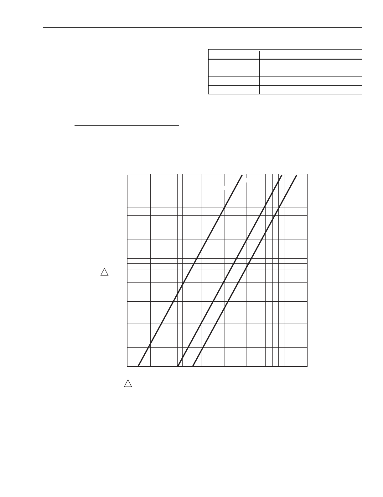
7. Plot the capacity (cfh) vs. pressure drop (psi) in Fig. 1 to
find the proper valve size.
NOTE: Use the corrected cfh for gas other than 0.64 sp gr.
1/4 INCH LARGE
1/8 INCH
1/4 INCH SMALL
3/8 INCH
1.5
PRESSURE
DROP (P SI)
1.0
.9
1
.8
.7
.6
.5
.4
.3
.25
.2
.15
.1
30 40 50 60 70 80 90 100 150 200 250 300 400 500 600 700 800 900 1000 150
1
TO CONVERT PRESSURE DROP IN INCHES WC TO PSI UNITS, MULTIPLY UNITS IN INCHES WC By .036
TO CONVERT PRESSURE DROP FROM PSI TO INCHES WC, MULTIPLY UNITS IN PSI BY 27.7.
FLO W (CFH ) OF NAT UR AL GA S SP . GR. .64
M20743
Fig. 1. Pressure drop (psi) vs.flow capacity (cfh) on V4046C, V8046C gas valves only.
Dimensions. See Fig. 2.
3 66-2008—3
Page 4

V4046C, V8046C MAGNETIC VALVES
DIM. B
1-3/4 (45)
Fig. 2. V4046C, V8046C approximate dimensions in in. (mm).
1/2-14 NPSM
36 IN. (915)
LEADS (2)
MODEL
V4046C,
V8046C
SEE TAB
BODY
SIZE
SMALL
SMALL
LARGE
LARGE
1-5/8
(41)
1-3/8
(35)
THREAD
SIZE
1/8-27 NPT
1/4-18 NPT
1/4-18 NPT
3/8-18 NPT
1-3/16
(30)
DIM. A
DIM. A DIM. B
IN MM IN MM
5/16
3/8
1/2
1/2
1-1/4 (32)
BASIC
CENTER
8
2-3/4
10
3
13
3-1/4
13
3-1/4
1-3/4 (45)
70
76
83
83
M16595
2-5/8 (67)
45°
BASIC
CENTER
8-32 x 1/4 IN.(6)
DEEP (2)
INSTALLATION
When Installing This Product…
1. Read these instructions carefully. Failure to follow them
could damage the product or cause a hazardous
condition.
2. Check the ratings given in the instructions and on the
product to make sure the product is suitable for your
application.
3. The installer must be a trained, experienced flame
safeguard technician.
4. After installation is complete, check out product
operation as provided in these instructions.
WARNING
Explosion and Electrical Shock Hazard.
Can cause serious injury, death or property
damage.
1. Turn off gas supply before beginning installation.
2. Disconnect electrical power before beginning
installation or servicing procedure. More than one
disconnect can be involved.
3. To avoid damage or distortion of the valve when
installing rigid or flexible conduit, the conduit fittings
should not be subjected to more than 5 ft-lbs torque
when screwing the fitting into the valve coil case
(powerhead). An approximation of 5 ft-lbs torque is
hand-tightened plus 1/8 turn. When securing the
rigid or flexible conduit in the conduit fitting using
the setscrew, use only enough force to secure the
conduit to avoid damage/distortion of the valve.
4. Always loosen the coil nut before attempting to
rotate the powerhead.
5. Do not tighten the valve on the gas pipe using the
coil housing (powerhead) as a handle.
Gas and Air Installations
Mount the gas valves in the pilot gas supply line upstream
from the burner. Ambient temperatures at the valve location
must be within -40°F to +125°F (-40°C to +54°C).
Mounting
The V4046C and V8046C Valves will operate in any mounting
position required by the installation, as long as gas flow is in
the direction indicated by the arrow.
Use iron pipe for at lease one of the valve connections to
insure adequate support and to confirm with
recommendations of Underwriters Laboratories, Inc.
If the installation does not support the valve adequately, a
mounting bracket should be devised and installed.
Preparing Piping and Installing Valve
1. Use new, properly reamed pipe, free from chips.
2. Do not thread pipe too far. Valve distortion or valve
malfunction may result from excess pipe in valve.
3. Apply a moderate amount of good quality pipe dope to
the pipe only (see Fig. 3). If pipe dope lodges on the
valve seat, it will prevent proper closure. If using LP
gas, use pipe dope resistant to action of LP gas.
4. Install the valve with gas flow in the direction indicated
by the arrow on the valve body. Gas must be in the
same direction as indicated by the arrow.
5. Move the powerhead to the desired position and then
tighten the hexagonal nut located on the top of the
valve.
66-2008—3 4
Page 5

V4046C, V8046C MAGNETIC VALVES
T:
EXCESS DOPE MAY BLOCK
,
T
M20744
D
M20746
P
A
TWO CLEAN
THREADS,
MODERATE
AMOUNT
OF DOPE
CORRECT:
NORMAL
FULL
THREAD
11USE PIPE DOPE RESISTANT TO ACTION OF LP GAS.
DISK OFF
VALVE
SEAT
LOOSE
CHIPS
INCORREC
TOO LONG
DISTORTS
VALVE SEA
Fig. 3. Preparing the pipe threads.
Gas and Air Applications
Test for leaks by painting pipe joints with a soapy solution.
Excessive bubbles indicate a leak.
WIRING
WARNING
Electrical Shock Hazard.
Can cause serious injury or death.
Disconnect power supply before wiring to prevent
electrical shock or equipment damage. More than one
disconnect can be involved.
All wiring must conform to local codes and ordinances.
Leadwires on these devices are long enough to reach the
junction box on most burner installation. The powerhead on all
models rotates 360 degrees, permitting the electrical service
to be brought to it from any convenient direction.
See Fig. 4 and 5 for typical wiring hookups for V4046C and
V8046C, respectively.
V4046C
PILOT VALVE
NEUTRAL SIDE OF
POWER SUPPLY
1 PROVIDE DISCONNECT MEANS AND OVERLOA
PROTECTION AS REQUIRED.
Fig. 4. Typical hookup of V4046C. See Flame Safeguard
wiring diagram to determine correct terminal for pilot
valve connection.
FLAME
SAFEGUARD
CONTROL
1
M20745
V4046C
PILOT VALVE
AT20 (OEM MODEL)
OR AT30
24V 60 HZ TRANSFORMER
L1
L2
(HOT)
OWER SUPPLY. PROVIDE DISCONNECT MEANS
ND OVERLOAD PROTECTION AS REQUIRED.
CONTROLLER
Fig. 5. Typical hookup of V8046C.
CHECKOUT AND SERVICE
Checkout
Put the system in operation and observe through at least one
cycle to be sure valve functions as described.
NOTE: Valve clicks audibly when it opens and when it
closes. Listen for clicks to make sure valve is
opening and closing properly.
Service
IMPORTANT
If the valve will not open when the thermostat and
limit control are calling for heat:
If the valve will not close with one or more of the
control contacts open:
Do not assume that the valve needs replacement
until all other sources of trouble have been
eliminated.
1. Make sure that the pilot is burning properly, the
Pilotstat® Control (if used) is holding in, and the limit
control contacts are closed.
2. Make sure that normal gas pressure is available at the
valve.
3. Make sure that the bleed line is unobstructed.
4. Check the power supply at the valve. If no voltage is
indicated, check the power source (transformer or line
source) and circuit controls. If proper voltage is present
at the valve, but the valve does not pull in, replace the
valve coil.
1. Make sure that the gas flow is in the direction of the
arrow on the valve body.
2. Check for a short in the wiring circuit.
5 66-2008—3
Page 6

V4046C, V8046C MAGNETIC VALVES
Maintenance
WARNING
Electrical Shock Hazard.
Can cause serious injury or death.
Disconnect the power supply before replacing the
solenoid coil. More than one disconnect can be
involved.
The V4046C and V8046C Magnetic Valves are built to give
long and reliable service without attention. If necessary, the
solenoid coil is replaced as follows (see Fig. 6):
1. Disconnect the power supply before replacing the
solenoid coil.
2. Remove the nut on top of the valve by turning it
counterclockwise .
3. Lift the powerhead assembly off the spindle.
4. Disconnect and remove the solenoid coil.
5. Connect the replacement coil and reassemble.
NOTE: The valve need not be removed from the pipe
installation to change the solenoid coil.
CASE
VALVE BODY
Fig. 6. Removing the solenoid coil.
NUT
INSULATING
PAPER
COIL
COVER
M20747
66-2008—3 6
Page 7

7 66-2008—3
Page 8

Automation and Control Solutions
Honeywell Honeywell Limited-Honeywell Limitée
1985 Douglas Drive North 35 Dynamic Drive
Golden Valley, MN 55422 Scarborough, Ontario
66-2008—3 G.R. Rev. 08-02 www.honeywell.com
M1V 4Z9
Printed in U.S.A. on recycled
paper containing at least 10%
post-consumer paper fibers.
 Loading...