

Page 1

Programmable Process Temperature Controller
© Copyright 2006, Maxitrol Company. All Rights Reserved.
www.maxitrol.com
USER’S / PROGRAMMING GUIDE
Page 2

Warnings
Inappropriate and/or improper installation, adjustment, alteration, service or maintenance can cause property damage, injury or death. Read the installation, operating and
maintenance instructions thoroughly before installing or
servicing this equipment.
Disconnect power before installation to prevent electrical
shock or equipment damage.
FOR YOUR SAFETY
If you smell gas: 1 Open windows.
Do not touch electrical switches.
2
Extinguish any open flame.
3
Immediately call your gas supplier.
4
FOR YOUR SAFETY
The use and storage of gasoline or other flammable vapors and liquids in open containers in the vicinity of this
control or other appliance is hazardous.
Please read these instructions fully prior to attempting to install, operate, and/or maintain the MP2 system. Failure to do so
may result in improper operation and/or component damage.
Installation shall conform with local codes, or in the absence
of local codes, in accordance with the National Fuel Gas Code
ANSI Z223.1/NFPA54 or CSA B149.1 as is applicable, and operated in accordance with the manufacturer’s instructions.
These instructions do not supersede OEM’s installation or operating instructions. Installation, inspection, and replacement
must be performed by a qualified installer or gas supplier.
This control must be electrically wired in accordance with local codes, or in the absence of local codes, with the National Electrical code, ANSI/NFPA 70 or the Canadian Electrical
Code, CSA C22.1 as applicable.
© Copyright 2006, Maxitrol Company. All Rights Reserved.
2
Page 3

General Statement
The MP2 system is intended for low temperature process applications,
for example paint spray booths or other curing processes. It is ideal for
temperature critical and time sensitive process applications requiring
temperatures from 60°F to 240°F.
Contents
Warnings ................................................................................................ 2
General Statement ................................................................................. 3
Contents ................................................................................................. 3
Features ................................................................................................. 4
Process Menu ..................................................................................... 4
Operation Menu .................................................................................. 4
Diagnostic Menu ................................................................................. 6
Other Features .................................................................................... 8
Technical Data ........................................................................................ 9
Components ........................................................................................... 9
Menus ................................................................................................... 10
Programming the MP2 System .............................................................11
Process Menu ................................................................................... 12
Operation Menu ................................................................................ 13
Diagnostic Menu ............................................................................... 15
Operation .............................................................................................. 16
MP2 Process Control System ........................................................... 16
MP2 Process Control System w/ TM02 Multifunctional Timer Control ... 17
Wiring Diagram ........................................................................................ 18
Glossary ............................................................................................... 19
© Copyright 2006, Maxitrol Company. All Rights Reserved.
3
Page 4

Features
Process Menu
Process Set Point
A maximum of (8) Process Set Points are available with a temperature
range of 60°F (15°C) to 240°F (115°C).
The Process Set Point is displayed as “SP.”
Process Set Points not being used can be turned to an “Off” setting.
Process Times (TM02 required)
Any of the (8) Processes can be timed. Each timed Process has a range of
00:00:01 to 23:59:59. The conclusion of a timed Process will immediately
proceed into the next Process. If the last Process of the program is timed, it
will proceed to the selected start position (see Looping Mode, page 7) after
timing out. The letter “T” will be displayed indicating a timed Process. Press
the up or down arrows on the TDM02 to scroll between the screens showing the Process Set Point and the sensed temperature AND the sensed
temperature with the time remaining in the Process (hh:mm:ss).
Operation Menu
Soft Start
The Soft Start feature controls the initial rate of voltage change to the modulator. Soft Start operates when switching from a lower Process temperature to a higher Process temperature. It is designed to slow the initial input
rate to the burner. This feature is available in three settings: slow, medium,
and fast and may be turned off. “Ss” (slow), “Sm” (medium) or “Sf” (fast)
is displayed during the time the Soft Start is active. This feature is comprehensive to all Set Points.
Max Valve VDC
This feature limits the maximum voltage applied to the modulator. It has a setting range of 7 to 25 VDC. This feature is comprehensive to all Set Points.
Max Ramp VDC
This feature limits the maximum voltage applied to the modulator while
operating in the Ramping mode. It has a setting range of 5 to 24 VDC. This
setting cannot exceed the maximum voltage output setting. This feature is
comprehensive to all Set Points.
Total Bandwidth
This feature determines the amount of temp. change required to drive the
modulator from the minimum fire setting to the maximum fire setting and
vice versa. This feature is used to eliminate pulsating or hunting due to an
oversensitive application. Increase the Bandwidth if a pulsating or hunting
condition exists for an extended period of time after a Set Point change.
The feature has a range of 5°F (2.8°C) to 15°F (8.3°C). Total Bandwidth is
comprehensive to all Set Points.
© Copyright 2006, Maxitrol Company. All Rights Reserved.
4
Page 5
Features
Offset Temp
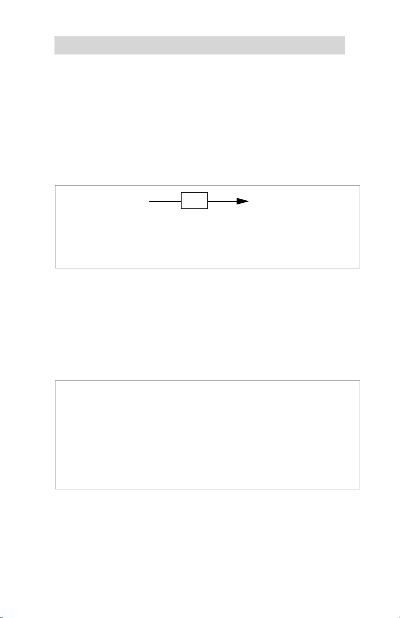
This feature is used to maintain a desired temperature in an area not being directly sensed by the MP2 system. The average difference between
the MP2 sensed discharged temperature and the desired space temperature must be known. This is the Offset. The Offset will set the MP2
sensed discharged air needed to produce the desired space temperature.
Decrease (-) the Offset to maintain and control space temperature lower
than MP2 discharged temperature. Increase (+) the Offset to maintain
and control space temperature higher than MP2 discharged temperature.
The space temperature will be displayed as the Process Set Point.
Example
1 Program Offset to -5°F.
2 Program Process Set Point (desired space temperature) to 75°F.
3 Therefore discharge air temperature = 80°F.
(Required MP2 discharge air temperature to maintain desired space temperature.)
4 The MP2 discharged air temp. is 80°F. The displayed Process Set Point is 75°F.
80°F -5°F 75°F
The feature has a range of -10°F (-5.6°C) to +10°F (5.6°C) and is available for each Process.
Ramping
This feature is used to step the input rate when changing from one Process Set Point to another. It is available for each Process. The Ramping
Rate determines the amount of temperature change per hour in one-minute steps. It has a range of 60 Deg/hr to 900 Deg/hr. The change can be
positive or negative.
Example
Process 1 = 75°F
Process 2 = 125°F
Process 2 Ramp Rate = 600 Deg/hr or 10 Deg/min
1 The control switches from Process 1 to Process 2.
2 The controller will immediately raise the temperature 10° and will hold it at the
new set point 85°F (75°F + 10°F) until 1 minute has passed.
3 It will continue to raise it 10° each subsequent minute until it meets Process 2.
4 It will take 5 steps (10°F each) and 4 minutes to go from 75°F to 125°F.
This feature can be used with Max Ramp VDC and Soft Start to smooth the
stepping. (Soft Start only works when Process Temperature increases.)
“Ramp” is displayed to indicate the Ramping feature is active.
© Copyright 2006, Maxitrol Company. All Rights Reserved.
5
Page 6

Features
Timers
The controller features two Timers (Timer 1 and Timer 2) that accumulate
the hours of operation for each Process. Each Process has a Timer 1 and
a Timer 2. The TM02 is required.
Timer 1
Timer 1 logs the hours of operation for a Process. It will log up 999 hours
at which time it will automatically reset to zero. The hours can be user
reset to zero at any time. It also has a programmable alarm setting to notify the user (by flashing a character in the lower right hand corner of the
display) when the desired accumulated hours for the Process have been
reached. It has a setting range of 1 to 999 hours. The feature is useful in
maintaining maintenance requirements.
Timer 2
Timer 2 logs the hours of operation for a Process. It will log up 999 hours
at which time it will automatically reset to zero. The hours can be user reset to zero at any time. The feature is useful in maintaining maintenance
requirements.
Diagnostic Menu
Max Proc Temp
This feature limits the maximum temperature for each Process. It has a
range of 60°F (15°C) to 240°F (115°C). It does not allow the Process Set
Point to be set in excess of the Maximum Process Temperature setting.
Min Proc Temp
This feature limits the minimum temperature for all Processes. It has a
range of 60°F (15°C) to 240°F (115°C). It does not allow any Process Set
Point to be set below the Minimum Process Temperature setting.
Calibration
This feature is used to fine-tune a particular application. Calibration shifts
the Bandwidth range up or down from the factory set mean. Each application is different with variances in burners and appliances. It can be necessary to change the midpoint of the modulation range to have the Process
Temperature and the actual sensed temperature match.
For sensed temperatures consistently displaying lower than the Set
Point, increase (+) Calibration by number of degrees off. For sensed
temperatures consistently displaying higher than the Set Point, decrease
(-) Calibration by number of degrees off. It is available for each Process
and has a range of –10°F (-5.6°C) to +10°F (5.6°C).
© Copyright 2006, Maxitrol Company. All Rights Reserved.
6
Page 7
Features
Monitor
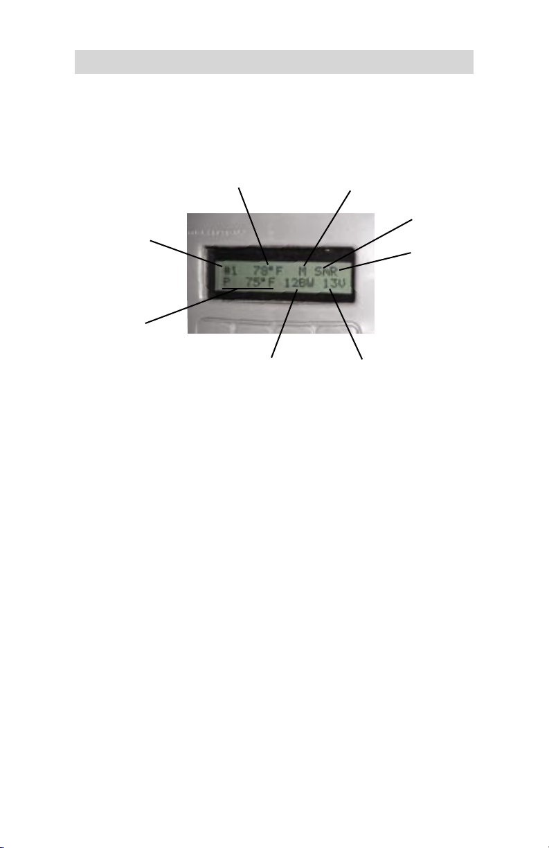
The Monitor feature is a useful tool when setting up or troubleshooting
the MP2 system. The following will appear on the display when Monitor
is in the “On” position:
Set Point Temperature
Process #
Sensed
Process
Temperature
Bandwidth
Manual or Timed
Soft Start
Ramp
VDC to Modulator
Looping Mode (TM02 applications only)
The looping mode feature is used to select the controllers default position
on startup and after the last process of a program is completed.
Selecting “READY”
Power up:
“READY” is displayed. Requires a momentary switch closure
to move the controller to the first process.
After last, manual process of a program:
After momentary switch closure to move out of the last process,
controller defaults to the “READY” position.
After last, timed process of a program expires:
Controller defaults to the “READY” position.
Selecting “First Process”
Power up:
Controller begins operating in the First Process of the program.
After last, manual process of a program:
After momentary switch closure to move out of the last process,
controller defaults to the First Process.
After last, timed process of a program expires:
Controller defaults to the First Process.
© Copyright 2006, Maxitrol Company. All Rights Reserved.
7
Page 8

Features
F/C Mode
This feature sets the control to operate in either the Fahrenheit (F) or
Celsius (C) mode.
NOTE: Changing between Fahrenheit and Celsius will reset the control to
factory default settings.
Software Version
Displays the version of software utilized by the controller.
Other Features
Process Indication Output
The TM02 multifunctional timer control features a Process Indication Output. Processes 1 thru 7 have a dedicated pair of terminals, labeled 1 thru 7
on the TM02. An indicator (LED, relay coil, etc...) 24 VDC 2 W maximum
can be wired directly to the corresponding terminal block for each Process to be indicated.
NOTE: Process #8 does not have a dedicated process indication output.
Program Indication Output
Terminal #8 is used to indicate the controller is operating within a Program. The following voltage will be measured across the #8 terminals:
Controller in the “READY” position
Controller operating in any of the 8 processes making up a Program
© Copyright 2006, Maxitrol Company. All Rights Reserved.
8
0 VDC
24 VDC 2W max
Page 9

Technical Data
NOTE:
The technical data listed in this manual does not include normal operating deviations that occur in the actual manufacturing process. The
listed specifications may not meet the individual unit’s actual specifications. Slight deviations in an individual unit’s performance may be
encountered due to possible changes in the controlled conditions in
which the unit is tested and calibrated. Check ratings given in OEM
instructions to assure the MP2 is suitable for the application.
Power
Requirements
Ambient
Temperature
Limits
Independent 24 VAC, 40 VA capacity transformer
Operating: -40°F(-40°C) to 158°F(70°C)
Non-operating: -40°(-40°C) to 185°F(85°C)
TDM02
Operating,
Non-operating: -40°(-40°C) to 185°F(85°C)
TM02
AM02
Connections
AM02 to TDM02 = Standard 6 Position 4 Conductor
Telephone Cable
AM02 to TM02 = Ethernet Patch Cord
Sensor
Valves
1,000 ohm RTD TS194Q use with mixing tube
M411, M511, M611, MR212
NOTE:
Please read safety warning instructions fully for Maxitrol Modulator
Valves [MI2040] prior to attempting to install, operate, and/or maintain the MP2 system.
Components
AM02 Amplifier
TDM02 Remote Selector Display Interface
TM02 Auxiliary Multifunctional Timer Control (optional)
Standard 6 Position 4 Conductor Telephone Cable, 3 feet
Ethernet Patch Cord, 3 feet
© Copyright 2006, Maxitrol Company. All Rights Reserved.
9
Page 10

Menus
Process Temperatures Temp Set Point Process #(1 - 8)
Off, 60°F (15°C) to 240°F (115°C)
Process Time Time Process #(1 - 8) Hours, Minutes, Seconds
TM02
Manual, 00:00:01 to 23:59:59
required
Soft Start Off, Slow, Medium, Fast
Max Valve VDC 7 to 25 VDC
Max Ramp VDC 5 to 24 VDC
Total Bandwidth 5°F(2.8°C) to 15°F (8.3°C)
Offset Temp Offset Temp Process #(1 - 8) -10°F(-5.6°C) to +10°F(5.6°C)
Ramping Ramping Process #(1 - 8) Off, 60 Deg/hr to 900 Deg/hr
Operation Menu
Timers Timer Process #(1 - 8)
TM02
Timer 1 View Hours, Clear Hours, Set Alarm Hours
required
Set Alarm 0 hrs to 999 hrs
Timer 2 View Hours, Clear Hours
Max Proc Temp Max Temp Process #(1 - 8) 60°F(15°C) to 240°F(115°C)
Min Proc Temp 60°F(15°C) to 240°F(115°C)
Calibration Calibration Process #(1 - 8) -10°F(-5.6°C) to +10°F(5.6°C)
Monitor On, Off
Looping Mode Ready, First Process
Diagnostic Menu Process Menu
F/C Mode
Software Version
© Copyright 2006, Maxitrol Company. All Rights Reserved.
10
Page 11
Programming the MP2
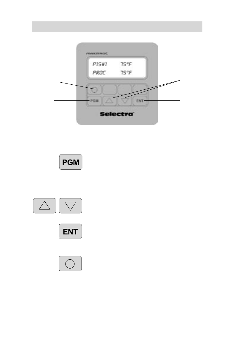
Button 1
Momentary
Switch
Program
Programming Buttons
Press once to initially enter programming mode.
Press once during programming to return to the
previous screen.
Press, hold for 5 seconds and release to EXIT
programming mode.
Press either to scroll or advance through menus.
Press either to change current value.
Press once to enter into the selected menu or
programming mode.
Press once to store programmed setting.
Up/Down
Arrows
Enter
Press and release once to switch to the next
Process or to move the controller from the
“READY” position to the First Process.
Press twice or hold for 10 seconds to
abort a timed process.
Screen Indicators
**STORED** will appear on the screen to confirm entry accepted.
T indicates a timed process.
M indicates a manual process.
© Copyright 2006, Maxitrol Company. All Rights Reserved.
11
Page 12
Programming the MP2
Programming
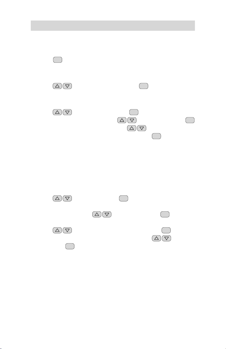
To enter the Process, Operation and Diagnostic Menus
Press
PGM
once.
Process Menu programming:
1
Scroll
to the Process Menu, press
ENT
.
Process Temperatures
2
Scroll
3
Temp Set Point Process #, scroll
4
Set Point Temp Process #, XX°F, set
to Temperatures, press
value (OFF, 60°F (15°C) to 240°F (115°C)), press
5
**Stored** will flash 4 times to confirm entry.
6
Repeat steps 2 through 5 for Set Points #(2 - 8).
NOTE: Process #1 CAN NOT be OFF. For unused Process Temperature
Set Points, press down arrow until “Off” is displayed. Set Points #(2 - 8)
are factory set to “Off.”
ENT
.
to Set Point #, press
Process Temperature
ENT
.
ENT
.
Process Times (TM02 required)
2
Scroll
to Times and press
Each Process can be either Timed or Manual.
3
Time Process #, scroll
MANUAL will be the default.
4
Scroll
a
Set Seconds, Minutes or Hours value with
press
**Stored** will flash 4 times to confirm entry.
b
Repeat steps 4 through 4b for each time segment.
c
to Seconds, Minutes or Hours, press
ENT
.
for Manual (untimed) Processes
Default setting or when programmed to 00:00:00.
d
Repeat steps 2 through 4 for Set Points #(2 - 8).
5
ENT
.
to Set Point #, press
ENT
ENT
.
.
,
© Copyright 2006, Maxitrol Company. All Rights Reserved.
12
Page 13

Programming the MP2
Operation Menu programming:
1
Scroll
to the Operation Menu, press
ENT
.
Soft Start
2
Scroll
3
Soft Start, scroll
4
**Stored** will flash 4 times to confirm entry.
to Soft Start and press
to Off, Slow, Medium or Fast, press
ENT
.
Max Valve VDC
2
Scroll
3
Max Valve VDC, set
4
**Stored** will flash 4 times to confirm entry.
to Max Valve VDC, press
voltage value (7 V to 25 V), press
ENT
.
Max Ramp VDC
2
Scroll
3
Max Ramp VDC, set
4
**Stored** will flash 4 times to confirm entry.
NOTE: Voltage can not be set greater than Max Valve VDC.
to Max Ramp VDC, press
voltage value (5 V to 24 V), press
ENT
.
ENT
ENT
ENT
.
.
.
Total Bandwidth
2
Scroll
3
Total Bandwidth, set
ENT
press
**Stored** will flash 4 times to confirm entry.
4
© Copyright 2006, Maxitrol Company. All Rights Reserved.
to Total Bandwidth, press
Bandwidth (5°F (-2.8°C) to 15°F (8.3°C)),
.
13
ENT
.
Page 14
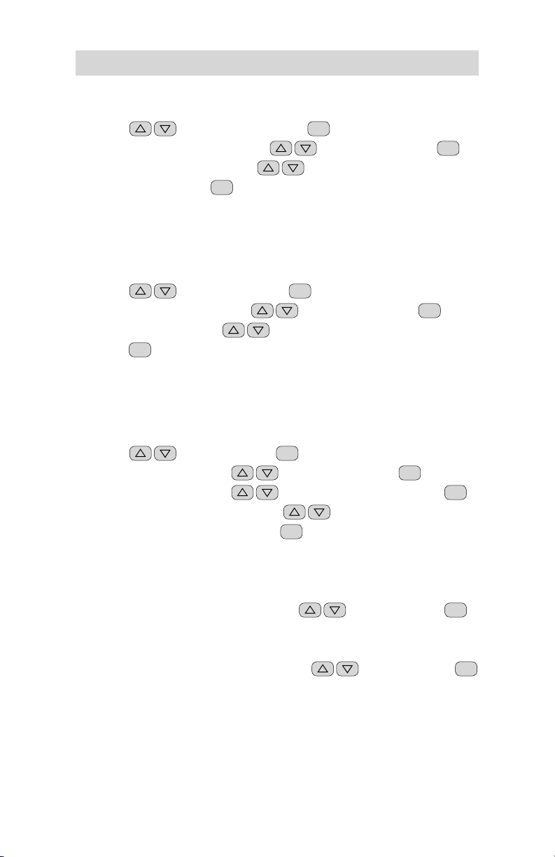
Programming the MP2
Offset
2
Scroll
3
Offset Temp Process #, scroll
4
Offset Temp Process #, set
10°F (5.6°C)), press
5
**Stored** will flash 4 times to confirm entry.
6
Repeat steps 2 through 5 for Set Points #(2 - 8).
to Offset Temp, press
ENT
.
ENT
Offset (-10°F (-5.6°C) to
Ramping
2
Scroll
3
Ramping Process #, scroll
4
Rmp Rate Proc #, set
ENT
press
5
**Stored** will flash 4 times to confirm entry.
6
Repeat steps 2 through 7 for Set Points #(2 - 8).
to Ramping, press
.
ENT
.
to Set Point #, press
Ramp Rate (Off, 60 to 900 Deg/Hr),
Timers (TM02 required)
2
Scroll
3
Timer Process #, scroll
4
Timer Process #, scroll
5
Timer 1: T1 Proc #, scroll
to Timers, press
or Set Alarm Hours, press
View hours
a
XXX Hours
Clear hours
b
Are You Sure? scroll
c
If Y, Timer1 Hrs Clear flashes to confirm entry.
Set alarm hours
d
T1 Proc # Alarm, scroll
Set Timer1 Alarm flashes to confirm entry.
e
ENT
.
to Set Point #, press
to Timer 1 or Timer 2, press
ENT
.
.
ENT
ENT
.
ENT
.
ENT
to Set Point #, press
to View Hours, Clear Hours
for Y or N, press
ENT
to set hrs, press
.
ENT
.
.
.
© Copyright 2006, Maxitrol Company. All Rights Reserved.
14
Page 15

Programming the MP2
6
Timer 2: T2 Proc #, scroll
ENT
Clear Hours, press
.
View hours
XXX Hours
a
Clear hours
Are You Sure? scroll
b
If Y, Timer2 Hrs Clear flashes to confirm entry.
c
Repeat steps 2 through 6 for Set Points #(2 - 8).
7
Diagnostic Menu programming
1
Scroll
to the Diagnostic Menu, press
Max Proc Temp
2
Scroll
3
Maximum Temp Process #, scroll
4
Max T Proc #, set
ENT
press
5
**Stored** will flash 4 times to confirm entry.
6
Repeat steps 2 through 5 for Set Points #(2 - 8).
to Max Proc Temp, press
Temp. value (60°F (15°C) to 240°F (115°C)),
.
to View Hours or
for Y or N, press
ENT
.
ENT
.
to Set Point #, press
ENT
ENT
.
.
Min Proc Temp
2
Scroll
3
Min Proc Temp, set
ENT
press
4
**Stored** will flash 4 times to confirm entry.
to Min Proc Temp, press
Temp. value (60°F (15°C) to 240°F (115°C)),
.
ENT
.
Calibration
15
ENT
.
2
Scroll
3
Calibration Process #, scroll to Set Point #, press
4
Cal Proc # set
ENT
press
**Stored** will flash 4 times to confirm entry.
5
Repeat steps 2 through 5 for Set Points #(2 - 8).
6
© Copyright 2006, Maxitrol Company. All Rights Reserved.
to Calibration, press
Temp. value (-10°F (-5.6°C) to 10°F (5.6°C)),
.
ENT
.
Page 16

Programming the MP2
Monitor
2
Scroll
3
Monitor set
4
Either Monitor Mode On or Off will flash 3 times to confirm.
to Monitor, press
On or Off, press
ENT
.
ENT
.
Looping
2
Scroll
3
Scroll
4
**Stored** will flash 4 times to confirm entry.
to Looping Mode, press
to READY or FIRST PROCESS, press
ENT
.
ENT
F/C Mode
2
Scroll
3
F/C MODE, scroll
4
**Stored** will flash 4 times to confirm entry.
NOTE: Changing between F and C will cause the MP2 system to reset to
factory defaults.
to F/C Mode, press
to either Fahrenheit or Celsius, press
ENT
.
Software Version
ENT
2
Scroll
Software Version information will appear.
3
to Menu Software Version, press
.
.
ENT
.
Operation
MP2 Process Control System
Switching to the Next Programmed Process
Push and release Button 1 on dial face (see page 11) or momentarily
latch (make) a set of contacts wired to the TB1 terminal (i.e. typically accomplished by a momentary ON (normally open) switch) to proceed to the
next Process. Pushing and releasing Button 1 or momentary latching of
TB1 during the last Process of a program will cause the MP2 System to
return to Process 1. Multiple contacts used to switch Processes are to be
wired in parallel.
Aborting a Process
Same as switching to next Process, push and release Button 1 or momentarily latch TB1.
© Copyright 2006, Maxitrol Company. All Rights Reserved.
16
Page 17

Operation
MP2 Process Control System w/
TM02 Multifunctional Timer Control
Switching to the Next Programmed Process
Timed processes
Nothing is required. The MP2 System will immediately proceed to the
next programmed Process after timing out.
NOTE: If the last Process of a program is timed, it will proceed either to the
“READY” position or to the First Process. By selecting the First Process in
the LOOPING Mode menu, the MP2 can be programmed into a continuous
program loop (see page 7, LOOPING Mode).
Untimed (Manual) Processes
An untimed Process will remain in the Process indefinitely until Button 1
is pushed and released or TB1 is momentarily latched. Pushing and releasing Button 1 or the momentary latching of the TB1 will cause the MP2
System to proceed to the next Process. If the last Process of a program
is untimed, pushing and releasing Button 1 or the momentary latching of
TB1 will cause the MP2 system to proceed to the selected program start
position. Multiple contacts used to switch untimed Processes are to be
wired in parallel.
Aborting a Timed Process
Push and release Button 1 or momentarily latch TB1 twice within a 10 second period or latch and hold continuously for 10 seconds.
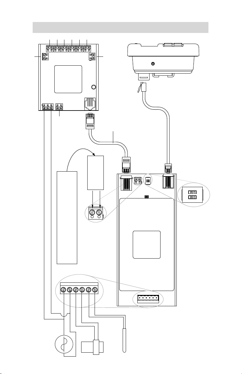
Connecting Indicator Relays
Process 1 thru 7 indicators use a corresponding pair of terminals, labeled
Relay (1 - 7), on the TM02. The Program indicator uses a corresponding
terminal labeled Relay 8. Wire each indicator (LED, relay coil, etc.) 24
VDC 2 W maximum directly to the desired corresponding terminal. See
figure A, page 18. Note polarity where applicable.
© Copyright 2006, Maxitrol Company. All Rights Reserved.
17
Page 18
J2
Wiring Diagram
2
3
4
5
6
7
- + - + - + - + - + - +
J8
- +
8
RELAY8
TB2
(OPTIONAL)
TM02
J2
- +
9
J5
1
- +
J3
RELAY1
D2
J1
TDM02
Ethernet Patch Cord
24VAC
Standard 6 Position 4 Conductor
Telephone Cable
(see the MP2 Installation Guide)
TB1
TB1
COM
J3
SETPOINT
Lockout Switch Settings
(see the MP2 Installation Guide)
21
OPEN
SW1
© Copyright 2006, Maxitrol Company. All Rights Reserved.
24VAC
Normally open device to momentarily
latch a set of contacts.
Multiple devices to be wired in parallel.
VALVE
1k PLT RTD
18
AM02
TB2
Fig. A
Wiring Diagram
Page 19

Glossary
Process
A single programmed temperature, or single programmed temperature
and time.
Program
The combination or series of Processes.
“Ready”
Screen display. When selected, it appears prior to the start of a program
involving timed processes. A momentary switch closure moves the controller from the “Ready” position to the First Process.
Manual Process
The (8) Processes can be manually timed. It is an infinite Process that
terminates when it is manually switched. A momentary switch closure input to the amplifier is required to proceed to the next Process. A Manual
Process displays the letter “M” to indicate it is not a timed Process.
“Manual”
Screen display. It describes the Manual Process.
Looping Mode (TM02 applications only)
The looping mode feature is used to select the controllers default position on startup and after the last process of a program is completed (see
page 7).
© Copyright 2006, Maxitrol Company. All Rights Reserved.
19
Page 20

MP2.UG.EN.07.2006
© Copyright 2005, Maxitrol Company. All Rights Reserved.
23555 Telegraph Road Southfield, MI 48033
248.356.1400 tel 248.356.0829 fax
www.maxitrol.com
 Loading...