

Page 1
184
J20741 - Subject to change. © Belimo Aircontrols (USA), Inc.
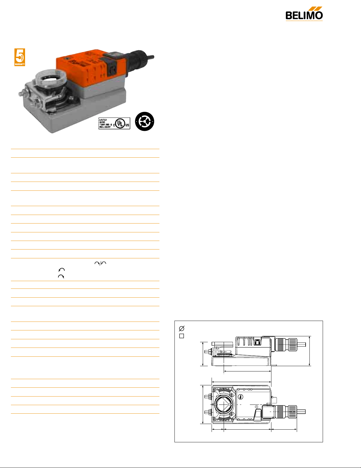
NMCB24-SR
Proportional Control, Non-Spring Return, Direct Coupled, 24V, for 2 to 10 VDC and 4 to 20 mA
Technical Data NMCB24-SR
Power Supply 24 VAC ± 20% 50/60 Hz
24 VDC ± 10%
Power Consumption 2.5 W (0.4 W)
Transformer Sizing 5 VA (Class 2 power source)
Electrical Connection 3 ft, 18 GA plenum rated cable
1/2” conduit connector
Overload Protection electronic throughout 0 to 95° rotation
Operating Range Y 2 to 10 VDC, 4 to 20 mA
Input Impedance 100 kΩ (0.1 mA), 500Ω
Feedback Output U 2 to 10 VDC (max 0.5 mA)
Angle of Rotation max. 95°, adjust. with mechanical stop
Torque 90 in-lb [10 Nm]
Direction of Rotation
reversible with switch. Actuator will move:
=CCW with decreasing control signal (10➞2V)
=CW with decreasing control signal (10➞2V)
Position Indication reflective visual Indicator (snap-on)
Manual Override external push button
Running Time 45 seconds, constant independent of load
Humidity 5 to 95% RH non condensing
(EN 60730-1)
Ambient Temperature -22°F to +122°F [-30°C to +50°C]
Storage Temperature -40°F to +176°F [-40°C to +80°C]
Housing NEMA 2/IP54
Housing Material UL94-5VA
Agency Listings† cULus acc. to UL 60730-1A/-2-14,
CAN/CSA E60730-1, CSA C22.2
No. 24-93, CE acc. to 89/336/EEC
Noise Level <45dB(A)
Servicing maintenance free
Quality Standard ISO 9001
Weight 1.7 lbs [0.75 Kg]
†Rated Impulse Voltage 800V, Type of action 1,
Control Pollution Degree 3.
Torque min. 90 in-lb for control of damper
surfaces up to 22 sq ft.
Application
For proportional modulation of dampers in HVAC systems.
Actuator sizing should be done in accordance with the
damper manufacturer’s specifications.
The actuator is mounted directly to a damper shaft up to 1.05"
in diameter by means of its universal clamp, 1/2” self centered
default. A crankarm and several mounting brackets are available for applications where the actuator cannot be direct coupled to the damper shaft.
The actuator operates in response to a 2 to 10 VDC, or with
the addition of a 500Ω resistor, a 4 to 20 mA control input
from an electronic controller or positioner. A 2 to 10 VDC
feedback signal is provided for position indication or masterslave applications.
Operation
The actuator is not provided with and does not require any
limit switches, but is electronically protected against overload.
The anti-rotation strap supplied with the actuator will prevent
lateral movement.
The NM series provides 95° of rotation and a visual indicator
indicates position of the actuator. When reaching the damper
or actuator end position, the actuator automatically stops. The
gears can be manually disengaged with a button on the actuator cover.
The NMCB24-SR… actuators use a sensorless Brushless DC
motor, which is controlled by an Application Specific
Integrated Circuit (ASIC). The ASIC monitors and controls the
actuator’s rotation and provides a digital rotation sensing
(DRS) function to prevent damage to the actuator in a stall
condition.Power consumption is reduced in holding mode.
Add on auxiliary switches or feedback potentiometers are
easily fastened directly onto the actuator body for signaling
and switching functions
Dimensions
(All numbers in brackets are in millimeters.)
2.36” [60]
3.15” [80]
4.88” [124]
3.66” [93]
3.9” [99]
0.98”
[25]
2.42” [61.4]
2” [50.8]
1/2” to 1.05” [12.7 to 26.67]
2/5” to 1.05” [10 to 26.67]
D121
O
L
A
H
B
r
u
s
h
l
e
s
s
D
M
©
O
r
o
t
o
M
C
®
Page 2
185
J20741 - Subject to change. © Belimo Aircontrols (USA), Inc.
NM
NMCB24-SR
Proportional Control, Non-Spring Return, Direct Coupled, 24V, for 2 to 10 VDC and 4 to 20 mA
NMCB24-SR - Typical Specification:
Proportional control damper actuators shall be electronic
direct-coupled type, which require no crankarm and linkage
and be capable of direct mounting to a shaft up to 1.05”
diameter. Actuators must provide proportional damper control in response to a 2 to 10 VDC or, with the addition of a
500Ω resistor, a 4 to 20 mA control input from an electronic
controller or positioner. Actuators shall have Brushless DC
motor technology and be protected from overload at all
angles of rotation. Actuators shall have reversing switch and
manual override on the cover. Run time shall be constant
and independent of torque. A 2 to 10 VDC feedback signal
shall be provided for position indication. Actuators shall be
cULus listed, have a 5-year warranty, and be manufactured
under ISO 9001 International Quality Control Standards.
Actuators shall be as manufactured by Belimo.
Accessories
K-NA Reversible Clamp
ZG-100 Universal Mounting Bracket
ZG-101 Universal Mounting Bracket
ZG-103 Universal Mounting Bracket
ZG-104 Universal Mounting Bracket
ZG-NMA Crankarm Adaptor Kit
AV8-25 Universal Shaft Extension
ZG-NMSA-1 Shaft Adaptor
ZS-T Terminal Cover for NEMA 2/IP54
ZS-100 Weather Shield - Steel
ZS-150 Weather Shield - Polycarbonate
Tool-06 8 mm & 10 mm Wrench
S1A, S2A Auxiliary Switch (es)
P370 Shaft Mount Auxiliary Switch
P…A Feedback Potentiometers
SGA24 Min positioners in NEMA 4 housing
SGF24 Min positioners for flush panel mounting
PTA-250 Pulse Width Modulation Interface
IRM-100 Input Rescaling Module
ADS-100 Analog to Digital Switch
ZG-R01 Resistor for 4 to 20 mA Conversion
NSV24 US Battery Back-Up Module
ZG-X40 Transformer
Note: When using NMCB24-SR… actuators, only use acces-
sories listed on this page.
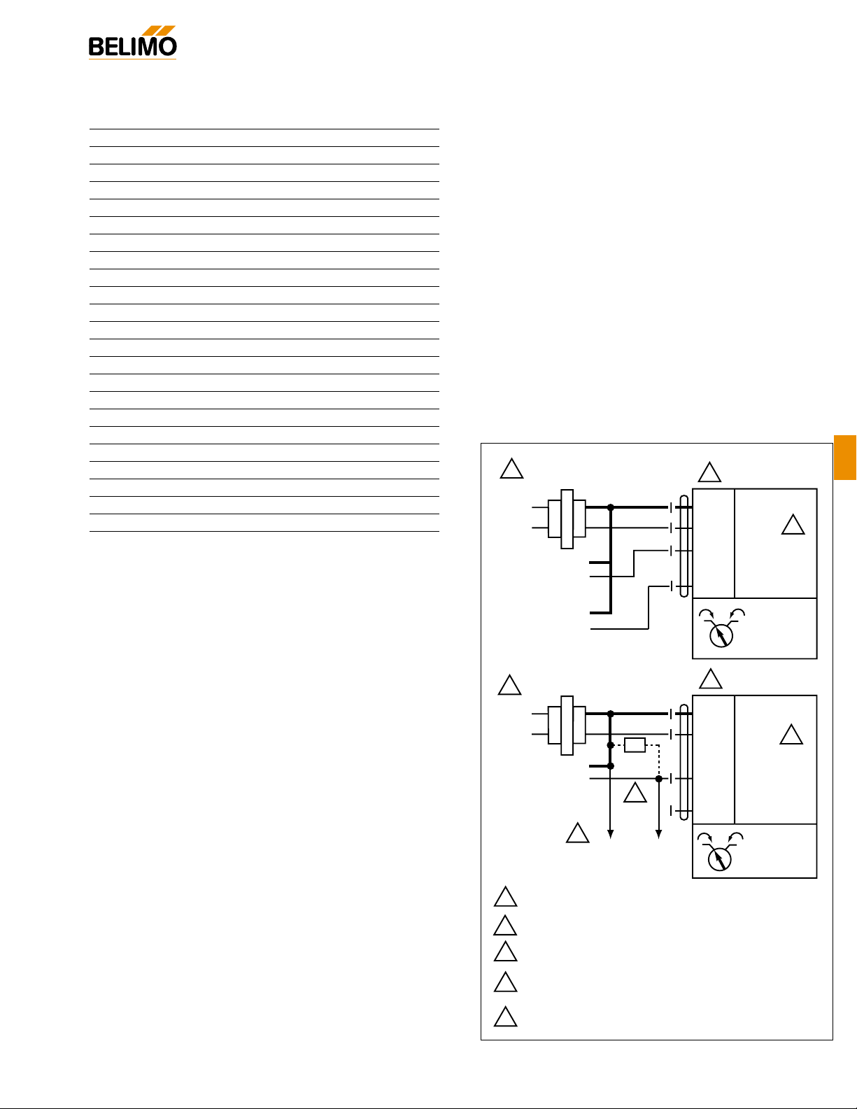
Wiring Diagram
W261
2 to 10 VDC and 4 to 20 mA control of NMCB24-SR
®
1
24 V AC Transformer
Line
Volts
Control Signal
2 to 10 VDC
2 to 10 VDC
Feedback Signal
(–)
(+)
(–)
(+)
2
Blk (1) Common
Red (2) Hot +
Wht (3) Y Input, 2 to 10V
Org (5) U Output, 2 to 10V
1 0
–
3
24 V AC Transformer
1
Line
Volts
2
Blk (1) Common
Red (2) Hot +
Ω
4 to 20 mA
Control Signal
(–)
(+)
500Ω
Wht (3) Y Input, 2 to 10V
4
Org (5) U Output, 2 to 10V
5
To other
actuators
1 0
Notes:
Provide overload protection and disconnect as required.
1
Actuators may be connected in parallel. Power
2
consumption and input impedance must be observed.
Actuator may also be powered by 24 VDC.
3
The ZG-R01 500Ω resistor converts the 4 to 20 mA
4
control signal to 2 to 10 VDC, up to 2 actuators may
be connected in parallel.
5
Only connect common to neg. (–) leg of control circuits.
–
3
Page 3
265
J20741 - Subject to change. © Belimo Aircontrols (USA), Inc.
Installation and Operation
Non-Spring Return
General Information
If more torque is required than one GM can provide, GM24B, GMB24-SR or GMX24-MFT may be installed on the same shaft.
Multiple Actuator Mounting
Preliminary Steps
1. Belimo actuators with NEMA 1 or NEMA 2 ratings should
be mounted indoors in a dry, relatively clean environment
free from corrosive fumes. If the actuator is mounted outdoors, a protective enclosure must be used to shield the
actuator.
2. For new construction work, order dampers with extended
shafts. Instruct the installing contractor to allow space for
mounting the Belimo actuator on the shaft.
For replacement of existing gear train actuators, there are two
options:
A. From a performance standpoint, it is best to mount the
actuator directly onto the damper shaft.
B. If the damper shaft is not accessible, mount the non-
spring return actuator with a ZG-NMA or ZG-GMA
crankarm kit, and a mounting bracket (ZG-100, ZG101, ZG-103, ZG-104)
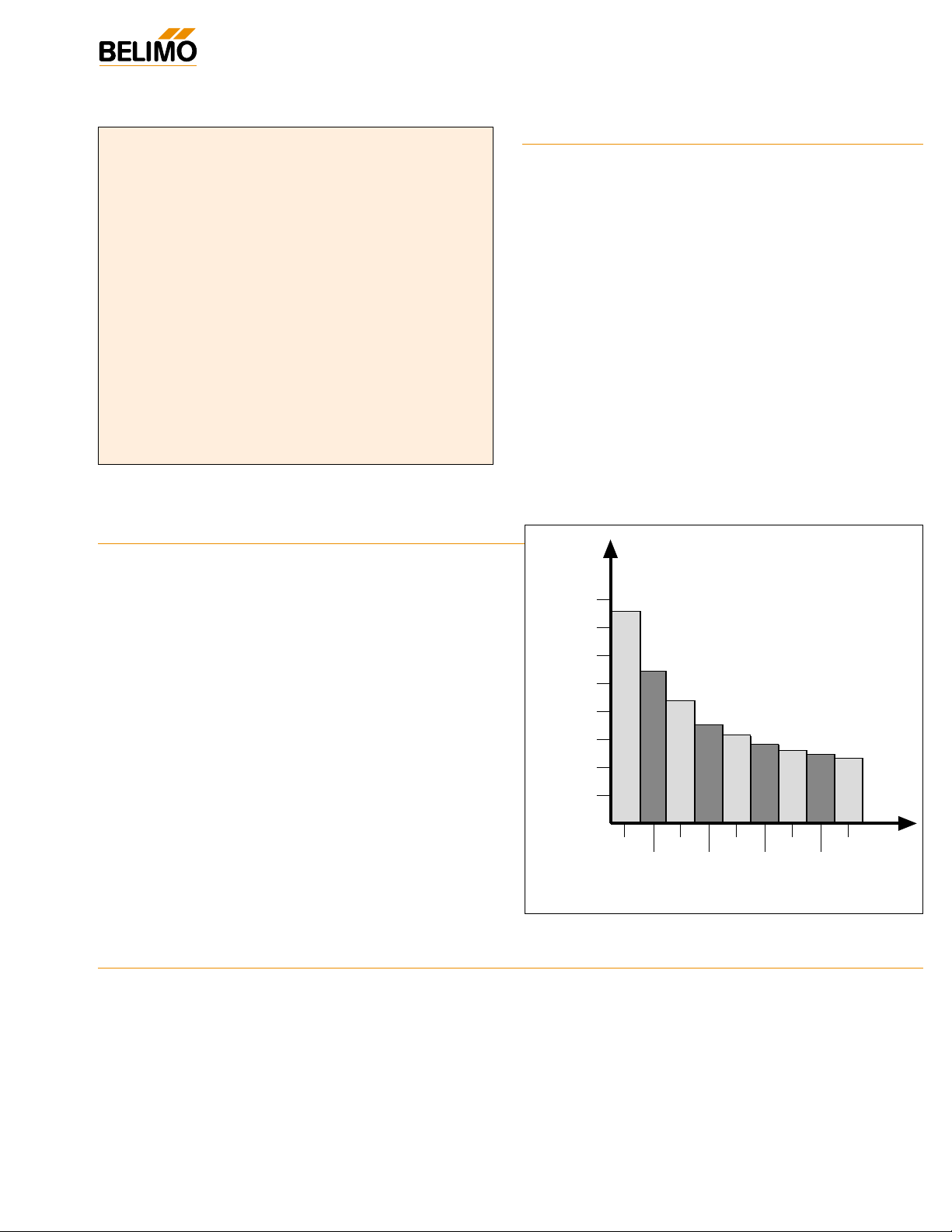
Torque Loading
Chart
Determining Torque Loading and Actuator Sizing
Damper torque loadings, used in selecting the correct size actuator, should be provided by the damper manufacturer. If this
information is not available, the following general selection
guidelines can be used.
Damper Type Torque Loading
Opposed blade, without edge seals, 3 in-lb/sq. ft.
for non-tight close-off applications
Parallel blade, without edge seals, 4 in-lb/sq. ft.
for non-tight close-off applications
Opposed blade, with edge seals, 5 in-lb/sq. ft.
for tight close-off applications
Parallel blade, with edge seals, 7 in-lb/sq. ft.
for tight close-off applications
The above torque loadings will work for most applications under
2 in. w.g. static pressure or 1000 FPM face velocity. For applications between this criteria and 3 in. w.g. or 2500 FPM, the
torque loading should be increased by a multiplier of 1.5. If the
application calls for higher criteria up to 4 in. w.g. or 3000 FPM,
use a multiplier of 2.0.
Table of Contents Page
General Mounting
❑ Standard ............................................266
❑ Reversible Clamp ..............................267
❑ Linear..................................................268
❑ Rotary ................................................269
❑ Retrofit Brackets ................................271
Operation
❑ Electrical ..............................................272
❑ Mechanical ..........................................273
Wiring
❑ General ..............................................274
❑ Accessories ........................................275
Startup and Checkout..................................278
®
140
120
100
80
60
40
20
Damper Area (sq. ft.)
0
2
Torque Loading (in-lb/ sq. ft.)
46810
3
579
Page 4
266
J20741 - Subject to change. © Belimo Aircontrols (USA), Inc.
65°
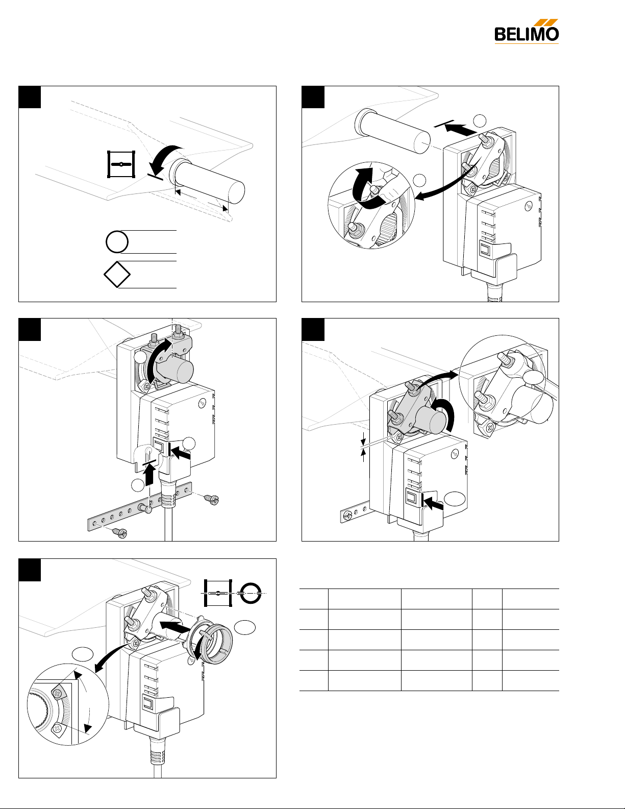
See next page for standard mounting instructions.
A* B C** D
LM 1/4” to 3/4” 5/16” to 3/4” 1.5” 4 to 5 ft-lb
NM 1/2” to 1.05” 2/5” to 1.05” 1.5” 6 to 7 ft-lb
AM 1/2” to 1.05” 2/5” to 1.05” 1.5” 6 to 7 ft-lb
GM 1/2” to 1.05” 2/5” to 1.05” 1.5” 6 to 7 ft-lb
*LM standard clamp has max 5/8” diameter. Accessory clamp
K-LM20 can be mounted for sizes up to 3/4” diameter.
NM, AM and GM clamps have an insert that self-centers on the
following diameter shafts: 1/2” (default), 3/4” and 1.05”.
**Shorter with reversible clamp for NM, AM, and GM
1 2
3
5
4
Installation Instructions
Quick-Mount Visual Instructions for Mechanical Installation
C
A
B
®
1
2
D
1
2
10
1
5°
2
1
1
2
Page 5
267
J20741 - Subject to change. © Belimo Aircontrols (USA), Inc.
Mounting Installation
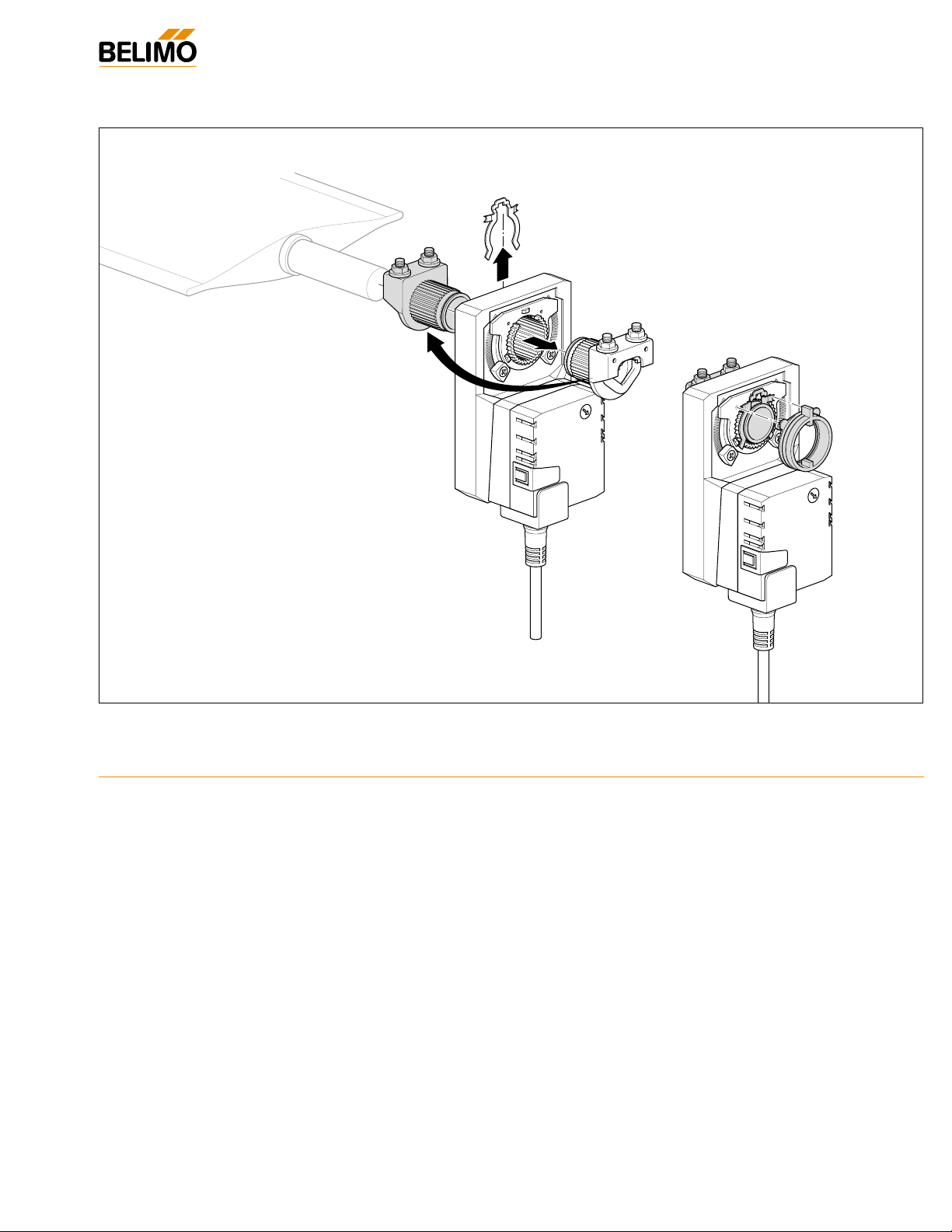
Reversible Clamp Quick Mount (NM, AM, GM)
1. Turn the damper shaft until the blades are fully closed.
2. ① Slip the actuator’s universal clamp over the damper shaft.
Make sure that the duct and the controls on the cover are
accessible. Place the actuator in the desired mounting position.
➁ Hand tighten the two nuts on the actuators universal clamp.
3. ① Disengage the actuator gear train by pressing the manual
override button and rotate the clamp until centered.
➁ Slide the anti-rotation strap up under the actuator so it
engages the actuator at the center cutout. Bend the bracket
as needed to support the rear of the actuator. Secure to
ductwork with self-tapping screws (No. 8 recommended).
4. ① Loosen the nuts on the universal clamp. Press the manual
override button and rotate the clamp to about 5° from the
closed position (1/16 to 1/8” between stop and clamp).
➁ Tighten the two nuts on the universal clamp with a 10 mm
wrench (see table for required torque).
5. ① Snap on the reflective position indicator.
➁ Adjust end-stops, if required
6. Mount actuators indoors. If mounted outdoors, use approved
protective enclosure.
The damper is now fully closed but the actuator is 5° from fully
closed. This is called “pre-loading” the actuator. When the
actuator is powered and sent to the closed position: it will put its
full torque on the shaft compressing the edge and blade seals.
This ensures that the damper will meet its leakage rating. The
actuator is electronically protected from overload and will not be
damaged.
Testing the Installation Without Power
1. Disengage the gear train with the manual override button
and move the shaft from closed to open to closed. Ensure
that there is no binding and that the damper goes fully open
and closes with 5° of actuator stroke left.
2. Correct any problems and retest.
Standard Mounting
®
 Loading...