

Page 1
Ordering Information
Basic Part No. Coil Voltage:
RU 4 S – ( ) – D12
# of Contacts
2 = DPDT
4 = 4PDT
42 = 4PDT bifurcated
contacts
Option*
(Blank) = with latching check
button
C = without check button
M = momentary check button
D = surge suppression diode (DC coils only)
Coil V oltage Code**
D12 = 12V DC
D24 = 24V DC
D110 = 110V DC
A24 = 24V AC
A110 = 110-120V AC
A220 = 220-240V AC
1. *All come with bi-polar LED, mechanical flag indicator, marking plate.
2. **Contact IDEC for other voltages.
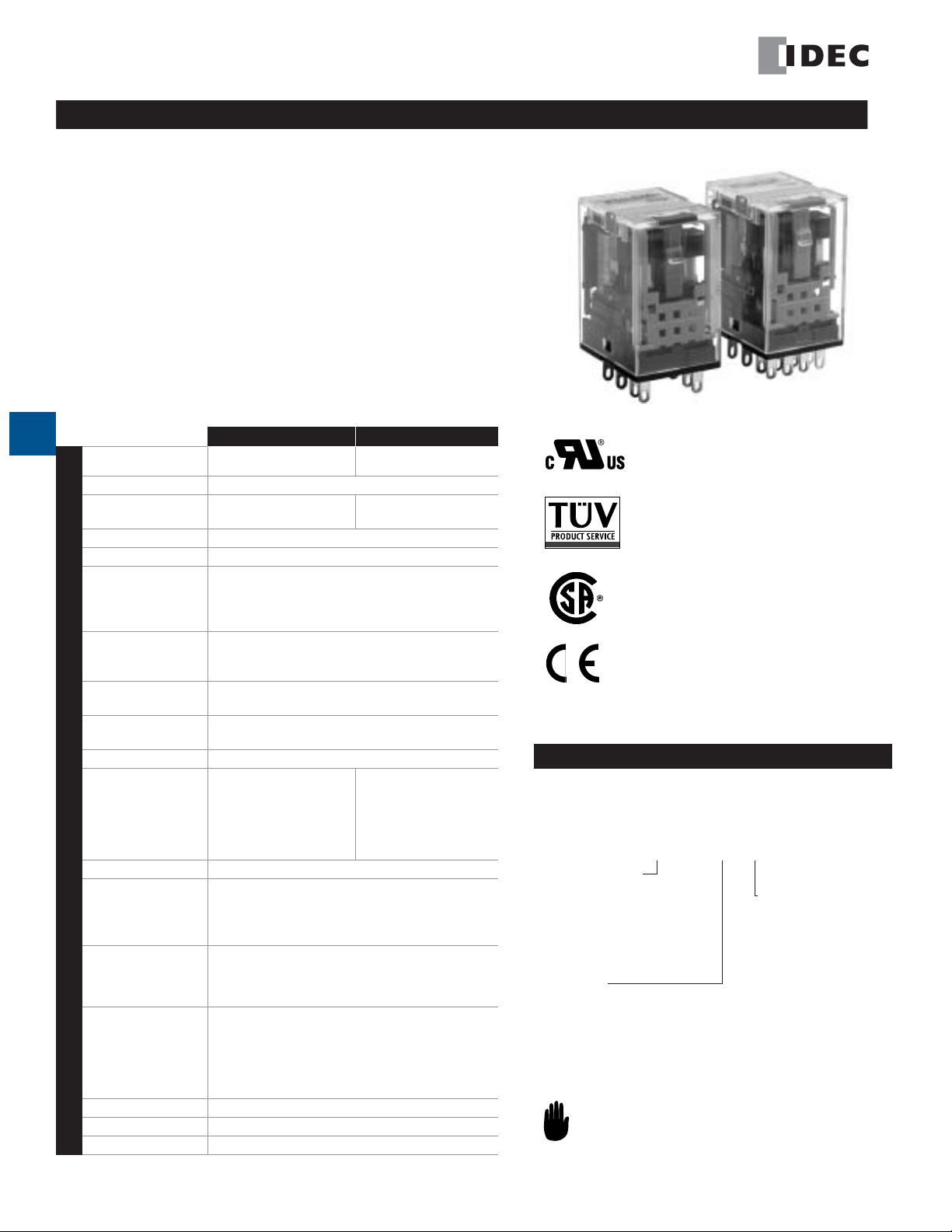
RU Series
RU Series — General Purpose Relays
Key features of the RU series include:
• Non-polarized LED indicator standard
• Solder-free construction (spot welded, no solder points, lead-free)
• No internal wires
• Mechanical flag indicator standard
• Manual latching lever with color coding for AC or DC coil
•Available without latching lever (or with momentary check button)
• Snap-on marking plate standard
• Cadmium-free contacts - RoHS compliant
• Color coded coils for visual distinction
• Contact rating 6A: 4PDT
10A: DPDT
E
Contact Material
Contact Resistance
Minimum
Applicable Load
Relays
Operating Time
Release Time
Maximum
Continuous Applied
Voltage
(AC/DC) at 20°C
Minimum
Operating Voltage
(AC/DC) at 20°C
Drop-Out Voltage
(AC) at 20°C
Drop-Out Voltage
(DC) at 20°C
Power Consumption
Dielectric Strength
Specifications
Frequency Response
Vibration Resistance
Shock Resistance
Life Expectancy
Degree of Protection
Operating Temperature
Weight
AgSnOIn (silver tin oxide
indium)
Between contact and coil:
2,500VAC, 1 minute
Between poles:
2,500VAC, 1 minute
Between contacts of the
same pole:
1,000VAC, 1 minute
RU2 RU4
50 m
Ω
maximum
24VDC, 5mA
(reference value)
20 msec maximum
20 msec maximum
110%
80%
30%
10%
1.1-1.4VA (AC); 0.9-1.0W (DC)
1,800 operations/hr
Operating extremes:
10 to 55Hz,
Amplitude 1.0 mm p-p
Damage limits: 10 to 55Hz,
Amplitude 1.0 mm p-p
Operating extremes:
150 m/s
Damage limits:
1,000 m/s
Mechanical:
AC: 20,000,000 operations
minimum
DC: 30,000,000 operations
minimum
Electrical:
see electrical life curve
IP40
-55 to +70°C (no freezing)
35g
AuAg/Ag (gold-silver alloy
on silver)
1V DC, 1mA (standard)
1V DC, 0.1mA (bifurcated)
Between contact and coil:
2,500VAC, 1 minute
Between poles:
2,000VAC, 1 minute
Between contacts of the
same pole:
1,000VAC, 1 minute
2
(15G)
2
(100G)
Relays
UL Recognized
File No. E66043, Vol 8, sec. 1
Vol 8, sec. 2
B020813332451
CSA Certified
File No. LR35144-135844
Consult factory for other voltages.
E-8
www.idec.com
USA: (800) 262-IDEC or (408) 747-0550, Canada: (888) 317-IDEC
Page 2
Relays RU Series
*DC
Part Numbers: RU Series with Options
Termination
S: Solder/plugin
Standard
Bifurcated 4PDT RU42S RU42S-C RU42S-M RU42S-D
Part Numbers: Sockets
Relays
RU2S SU2S-11L SM2S-05 SM2S-05C
RU4S SU4S-11L SY4S-05 SY4S-05C
Spring Clamp
DIN Rail Mount
See Section F for details on sockets. All DIN rail mount
sockets shown above can be mounted using DIN rail BNDN1000.
Contact
Configuration
DPDT RU2S RU2S-C RU2S-M RU2S-D
4PDT RU4S RU4S-C RU4S-M RU4S-D
Standard DIN
Rail Mount
Standard
Finger-Safe DIN
Rail Mount
Part Numbers
Without
Latching Lever
Panel Mount PC Mount
SY4S-51
With Momentary
Check Button
SY4S-61
SY4S-62
With Diode*
coils only.
Springs & Clips (optional)
Part Number Use With
SFA-101①
SFA-202
SY4S-02F1➂
SFA-301①
SFA-302
SY4S-51F1➂
use with SY4S-05, -05C
➁
SM2S-05, -05C
SU4S-11L, SU2S-11L
➁
use with SY4S-51, -61
① Top latch
➁ Side latch
➂ Pullover spring
E
Relays
Part Numbers: Marking Strip Marking Strip Color Code
Item Part Number Quantity Color Code Color Code
RU Marking Strip RU9Z-P①PN10, 10 pieces per package Yellow* Y Blue S
In place of ①, insert color code
from chart at right.
Green G White W
Amber A
*yellow marking
strip standard on
all RU relays.
Ratings
Coil Ratings
Rated Voltage Voltage Code
24V A24
AC
110-120V A110
220-240V A220
12V D12
DC
24V D24
110V D110
*Voltage printed in black.
Coil Tape
Colors
white 37.5mA 164 Ω 60mA 1.8H 0.96H
dark blue 8.4mA 4,550 Ω 14mA 36H 22H
red 4.2mA 18,230Ω 7mA 144H 87H
yellow* 83.3mA 160 Ω
green 41.7mA 605 Ω
yellow* 9.1mA 12, 100 Ω
Rated Current ±15%
at 20°C
Coil Resistance
±10% at 20°C
Inrush
Current
Energizing De-Energizing
Inductance
N/A
Contact Ratings (Standard) Contact Ratings (Bifurcated)
Voltage Resistive Inductive Voltage Resistive Inductive
30V DC
110V DC
120V AC
240V AC
www.idec.com USA: (800) 262-IDEC or (408) 747-0550, Canada: (888) 317-IDEC E-9
DPDT 10A 5A 30V DC 4PDT 3A 1.5A
4PDT 6A 3A 110V DC 4PDT – –
DPDT 0.6A 0.3A 120V DC 4PDT 3A 0.8A
4PDT 0.4A 0.2A 250V DC 4PDT 3A 0.8A
DPDT 10A 5A
4PDT 6A 3A
DPDT 10A 5A
4PDT 6A 3A
Page 3

RU Series Relays
DC110V
Load Current (A)
DC30V
AC250V
6 3 10.50.1
10
100
1
50
500
6
DC110V
0.1 0.5 1 3
AC250V
DC30V
Load Current (A)
DC L/R=7ms
AC COS =0.3
500
50
1
100
1000
10
DC110V
AC250V
DC30V
Load Current (A)
500
50
1
100
10
0.1 0.5 1 3 6
0.02
DC L/R=7ms
AC COS =0.3
DC110V
DC30V
AC250V
10
100
1
50
500
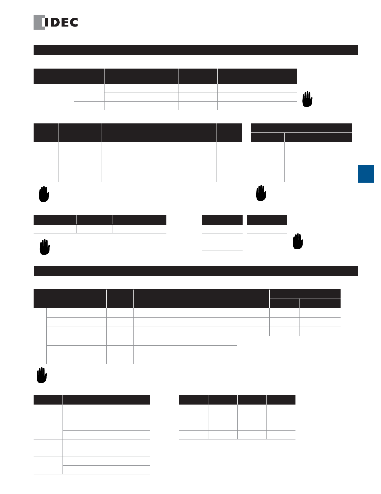
Internal Circuit*
RU2S Standard RU2S-D with Diode RU4S/RU42S Standard RU4S-D/RU42S-D with Diode
(4)42(3)32(2)22
(8)44(7)34(6)24(5)14
(12)41(11)31(10)21(9)11
(14)A2
(13)A1
(4)42(1)12
(8)44(5)14
(12)41(9)11
(14)A2
(1)12 (4)42
(5)14 (8)44
(9)11 (12)41
(13)A1
(14)A2
(1)12 (2)22 (3)32
(5)14 (6)24 (7)34 (8)44
(9)11 (10)21 (11)31 (12)41
(13)A1
(4)42
(14)A2
(1)12
(13)A1
Over 24V AC/DC
(1)12 (4)42
(5)14 (8)44
(9)11 (12)41
(13)A1
24V AC/DC or less
E
Relays
Over 24V DC
(4)42(1)12
(8)44(5)14
(12)41(9)11
(14)A2
(13)A1
(14)A2
24V DC or less
Image as viewed from bottom of relay. Refer to socket for exact
wiring layout (Section F)
RU2 (Resistive Load)
AC250V
DC30V
1000
DC110V
.
500
100
50
10
(x 10,000 operations)
Electrical Life Curves
RU4 (Resistive Load)
1000
(x 10,000 operations)
Over 24V AC/DC
(3)32(2)22(1)12
(4)42
(8)44(7)34(6)24(5)14
(12)41(11)31(10)21(9)11
(13)A1
(14)A2
24V AC/DC or less
Numbers not in parenthesis follow international system
of labeling terminals.
Over 24V DC
(1)12 (2)22 (3)32 (4)42
(5)14 (6)24 (7)34 (8)44
(9)11 (10)21 (11)31 (12)41
(13)A1
24V DC or less
RU42 (Resistive Load)
(x 10,000 operations)
(14)A2
1
Load Current (A)
RU2 (Inductive Load)
AC250V DC30V
DC110V
10 5 10.50.1
RU4 (Inductive Load)
0.1 0.5 1 3 60.02
Load Current (A)
RU42 (Inductive Load)
1000
500
100
50
10
(x 10,000 operations)
E-10 www.idec.com USA: (800) 262-IDEC or (408) 747-0550, Canada: (888) 317-IDEC
AC COS =0.3
DC L/R=7ms
1
0.1 0.5 1 5 10
Load Current (A)
(x 10,000 operations)
(x 10,000 operations)
Page 4

Relays RU Series
Dimensions are in mm.
RU4 (Maximum Load)
6
3
1
Load Current (A)
0.1
DC resistive
DC inductive
L/R = 7 ms
Maximum Switching Capacity
RU2 (Maximum Load)
10
5
1
Load Current (A)
0.1
DC resistive
DC inductive
L/R = 7 ms
10 30 100 250500
AC resistive
AC inductive
(cos ø = 0.3)
Load Voltage(V)
AC resistive
RU42 (Maximum Load)
6
3
1
Load Current (A)
0.1
AC inductive
(cos ø = 0.3)
DC resistive
DC inductive
L/R = 7 ms
AC resistive
AC inductive
(cos ø = 0.3)
E
Relays
10 30 100 250 500
Load Voltage(V)
Dimensions & Mounting Hole Layouts
RU2
Dimensions
Marking Plate
Removal Slot
0.5
21.0
14
58912
27.5
Marking plate removal slot is provided only on one side.
Insert a flat screwdriver into the slot to remove the marking plate.
1.2 ◊ 2.2 Hole
14
13
35.06.4
2.6
10 30 100 250 500
Load Voltage(V)
RU4/RU42
Dimensions
Marking Plate
Removal Slot
21.0
0.5
4321
8
121110
765
9
27.5
1.2 ◊ 2.2 Hole
1413
35.06.4
2.6
Marking plate removal slot is provided only on one side.
Insert a flat screwdriver into the slot to remove the marking plate.
Dimensions are in mm.
www.idec.com USA: (800) 262-IDEC or (408) 747-0550, Canada: (888) 317-IDEC E-11
 Loading...