

Page 1
GT3A Series Timers
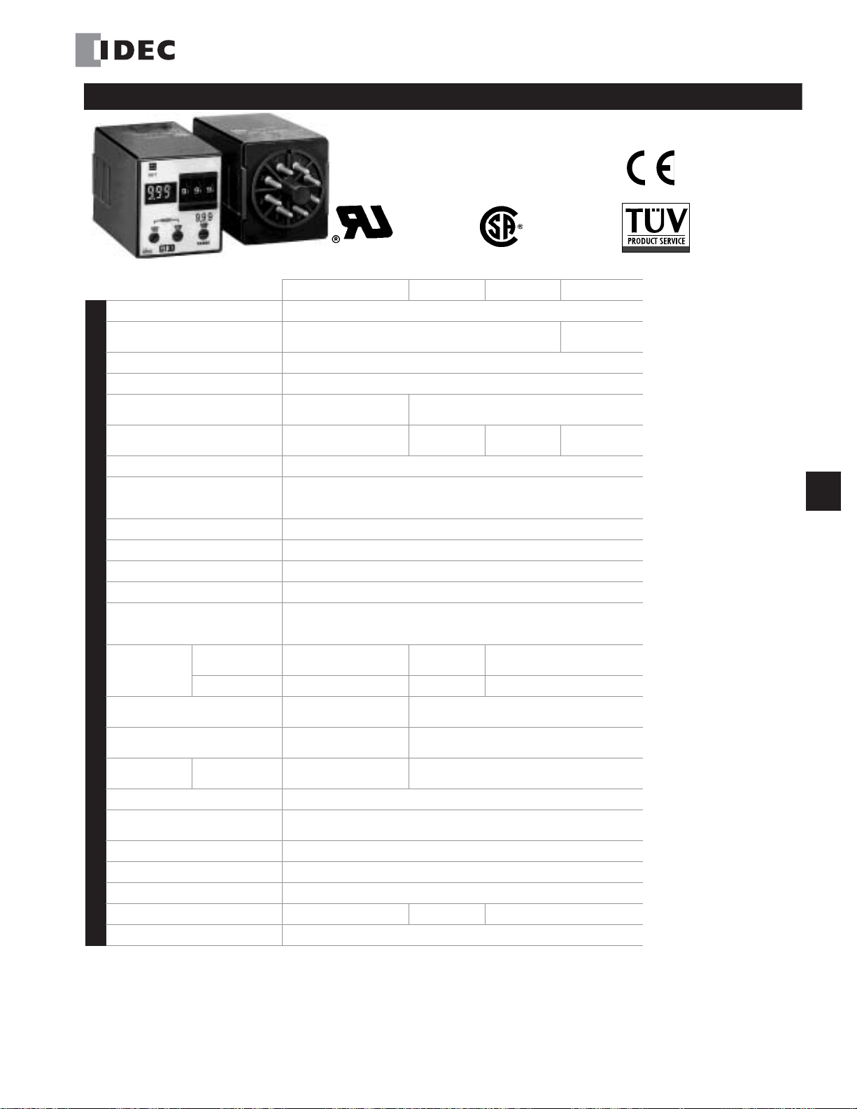
GT3A Series — Analog Timers
G
Timers
Operation
Time Range
Rated Voltage
Contact Ratings
Minimum Applicable
Load
Voltage Tolerance
Error
Setting Error
Reset Time
Insulation Resistance
Dielectric Strength
Specifications
Power Consumption
(approximate)
Mechanical Life
Electrical LIfe
Weight (approximate)
Vibration Resistance
Shock Resistance
Operating Temperature
Operating Humidity
Storage Temperature
Housing Color
UL, c-uL Listed
File No. E55996
Key features of the GT3A series include:
• 4 selectable operation modes on each model
• External start, reset, and pause inputs
• Panel mount or socket mount
• Large variety of timing functions
• Power and output status indicating LEDs
GT3A-1 GT3A-2 GT3A-3 GT3A-4,-5,-6
Multi-mode Multi-mode with inputs (11 pins)
0.05s to 180 hours
100 to 240V AC, 50/60Hz
12V DC
24V AC, 50/60Hz / 24V DC
125V AC/250V AC, 3A;
30V DC, 1A (resistive load)
5V, 10mA (reference value)
AF20 (100V AC): 85 to 264V AC
AD24: 20.4 to 26.4V AC/21.6 to 26.4V DC
D12: 10.8 to 13.2V DC
±0.2%, ±10 msec (repeat, voltage, temperature)
±10% maximum
60msec maximum
100MΩ minimum
Between power and output terminals: 2,000V AC, 1 minute
Between contacts of different poles: 2,000V AC, 1 minute
Between contacts of the same pole: 750V AC, 1 minute
Delayed SPDT
10.8VA
(200V AC, 60Hz)
–
10,000,000 operations minimum 5,000,000 operations minimum
50,000 operations minimum (rated load) 100,000 operations minimum (rated load)
63g 73g 79g 80g
Delayed SPDT +
instantaneous SPDT
13.5VA
(200V AC, 60Hz)
12VDC/1W 12VDC/1.1W 12VDC/0.8W
24VDC/0.7W
24VAC/1.2VA
100m/sec2 (approximate 10G)
Operating extremes: 100m/sec2 (approximate 10G)
Damage limits: 500m/sec2 (approximate 50G)
Delayed DPDT Delayed DPDT
14.4VA
(200V AC, 60Hz)
24VDC/0.6W
24VAC/1.3VA
–10 to +50°C
45 to 85% RH
–30 to +80°C
Gray
125V AC/250V AC, 5A;
30V DC, 5A (resistive load)
4.7VA (100V AC, 60Hz),
14.4VA (200V AC, 60Hz)
24VDC/0.6W
24VAC/1.3VA
Specifications — G-14
Part Number List — G-15
Timing Diagrams/Schematics — G-16
Instructions: Setting Timer — G-22
GT3 Accessories — G-48
GT3 Instructions: Wiring Inputs — G-50
GT3 Dimensions — G-52
Timing Diagrams Overview — G-4
GT3A Table of Contents
G-14 www.idec.com USA: (800) 262-IDEC or (408) 747-0550, Canada: (888) 317-IDEC
Page 2
Timers GT3A Series
Part Number List
Part Numbers: GT3A-1, -2, -3
Mode Of
Operation
A: ON-delay 1
B: Interval 1
C: Cycle 1
D: Cycle 3
1. F or wiring sc hematics and timing dia grams for GT3A-1, -2, -3, see pa ges G-16, G-17, or G-18 respectively.
2. For more details about time ranges, see instructions on page G-22.
3. For socket and accessory part numbers, see page G-48.
Rated Voltage Code
AF20: 100 to 240V AC (50/60Hz)
AF20: 100 to 240V AC (50/60Hz)
D12: 12V DC
AD24: 24V AC (50/60Hz)/24V DC
Part Numbers: GT3A-4, -5, -6
Mode of
Operation
A: ON-Delay 2
B: Cycle 2
C: Signal ON/OFF-Delay 1
D: Signal OFF-Delay 1
A: Interval 2
B: One-Shot Cycle
C: Signal ON/OFF-Delay 2
D: Signal OFF-Delay 2
A: One-Shot
B: One-Shot ON-Delay
C: One-Shot 2
D: Signal ON/OFF-Delay 3
4. For wiring schematics and timing diagrams GT3A-4,-5,-6, see pages G-19, G-20, and G-21 respectively.
5. For more details about time ranges, see instructions on page G-22.
6. A (11-pin) and B (11-pin) differ in the way inputs are wired.
7. For socket and accessory part numbers, see page G-48.
8. For the timing diagrams overview, see page G-4.
Rated Voltage Code
AF20: 100 to 240V AC (50/60Hz)
D12: 12V DC
AD24: 24V AC (50/60Hz)/24V DC
AF20: 100 to 240V AC (50/60Hz)
AD24: 24V AC (50/60Hz)/24V DC
Time
Range
0.05s.
to
180
hours
Time
Range
0.05
seconds
to
180 hours
Output Contact
Delayed SPDT GT3A-1AF20 GT3A-1EAF20
250V AC, 3A,
30V DC, 1A
(resistive load)
240V AC, 5A,
24V DC, 5A
(resistive load)
Delayed SPDT +
Instantaneous
SPDT
Delayed DPDT
Output Contact Input
250V AC, 5A,
24V DC, 5A
(resistive load)
Delayed
DPDT
Complete Part No.
8-Pin 11-Pin
GT3A-2AF20 GT3A-2EAF20
GT3A-2D12 GT3A-2ED12
GT3A-2AD24 GT3A-2EAD24
GT3A-3AF20 GT3A-3EAF20
GT3A-3D12 GT3A-3ED12
GT3A-3AD24 GT3A-3EAD24
Complete Part No.
A (11-pin) B (11-pin)
GT3A-4AF20 GT3A-4EAF20
GT3A-4D12 GT3A-4ED12
GT3A-4AD24 GT3A-4EAD24
GT3A-5AF20 GT3A-5EAF20
Start
Reset
Gate
GT3A-5AD24 GT3A-5EAD24
GT3A-6AF20 GT3A-6EAF20
GT3A-6AD24 GT3A-6EAD24
G
Timers
www.idec.com USA: (800) 262-IDEC or (408) 747-0550, Canada: (888) 317-IDEC G-15
Page 3
GT3A Series Timers
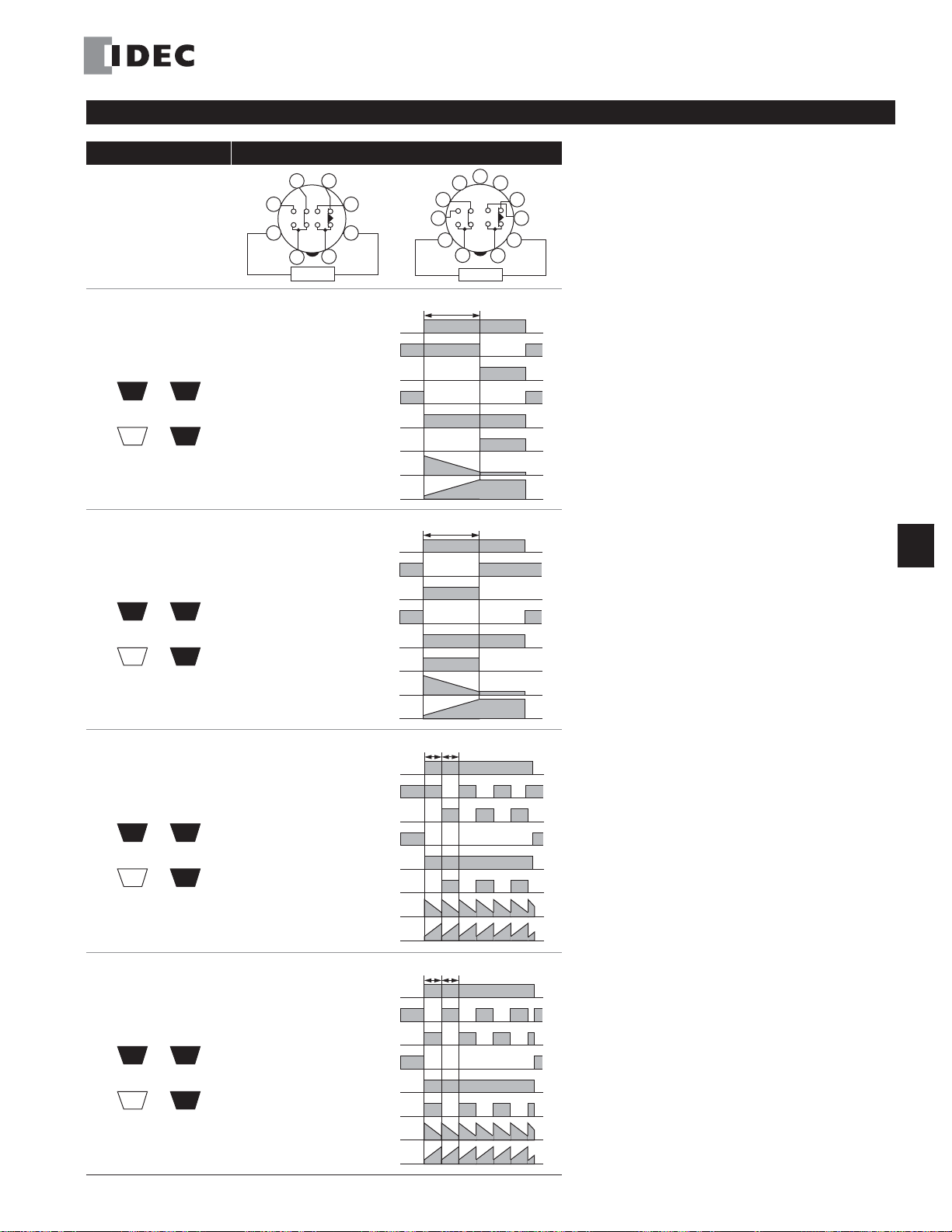
Timing Diagrams/Schematics
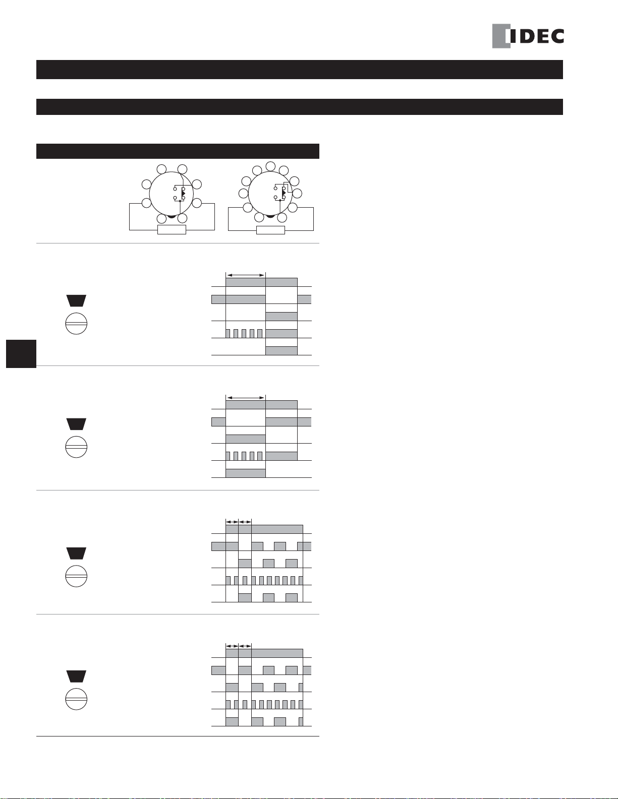
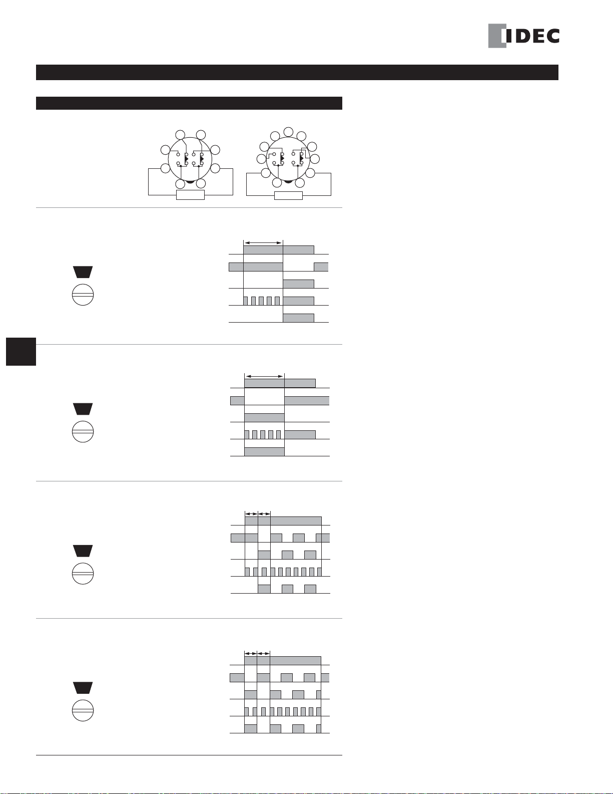
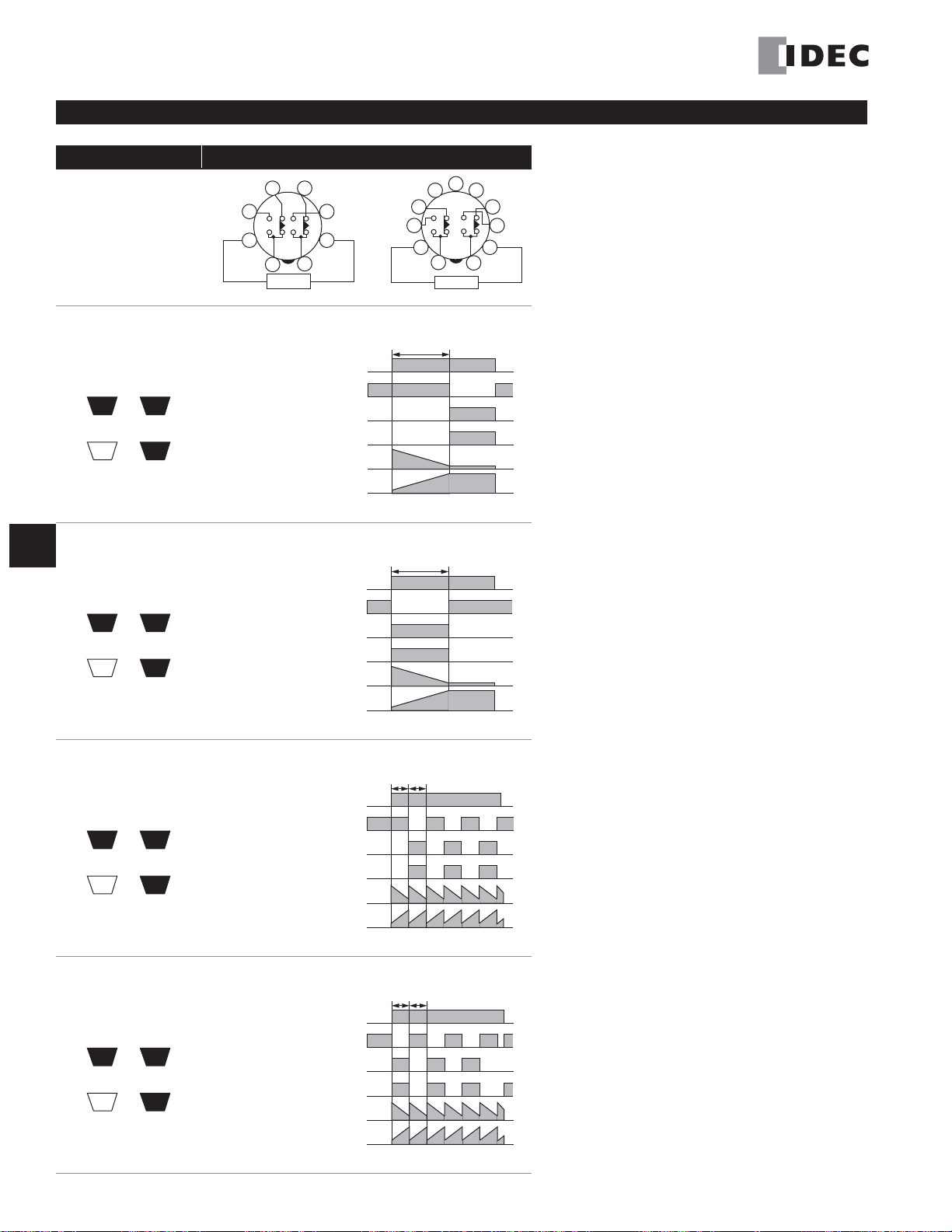
GT3A- 1 Timing Diagrams
Delayed SPDT
6
57
3
2
1
POWER
84
9
10
(+)(-)
11
Operation
Mode Selection
8-Pin 11-Pin
3
2
4
1
POWER
5
6
7
(+)(-)
8
G
Timers
ON-Delay 1
MODE
A
Interval 1
MODE
B
Cycle 1
(OFF first)
MODE
C
Item
Power
Delayed
Contact
Indicator
Item
Power
Delayed
Contact
Indicator
Item
Power
Delayed
Contact
Indicator
Terminal No. Operation
2-7 (8p)
(Power)
2-10 (11p)
5-8 (8p)
(NC)
8-11 (11p)
6-8 (8p)
(NO)
9-11 (11p)
POWER
OUT
Terminal No. Operation
2-7 (8p)
(Power)
2-10 (11p)
5-8 (8p)
(NC)
8-11 (11p)
6-8 (8p)
(NO)
9-11 (11p)
POWER
OUT
Terminal No. Operation
2-7 (8p)
(Power)
2-10 (11p)
5-8 (8p)
(NC)
8-11 (11p)
6-8 (8p)
(NO)
9-11 (11p)
POWER
OUT
Set Time
Set Time
Set Time
Cycle 3
(ON first)
MODE
Item
Power
D
Delayed
Contact
Indicator
Terminal No. Operation
2-7 (8p)
(Power)
2-10 (11p)
5-8 (8p)
(NC)
8-11 (11p)
6-8 (8p)
(NO)
9-11 (11p)
POWER
OUT
Set Time
G-16 www.idec.com USA: (800) 262-IDEC or (408) 747-0550, Canada: (888) 317-IDEC
Page 4
Timers GT3A Series
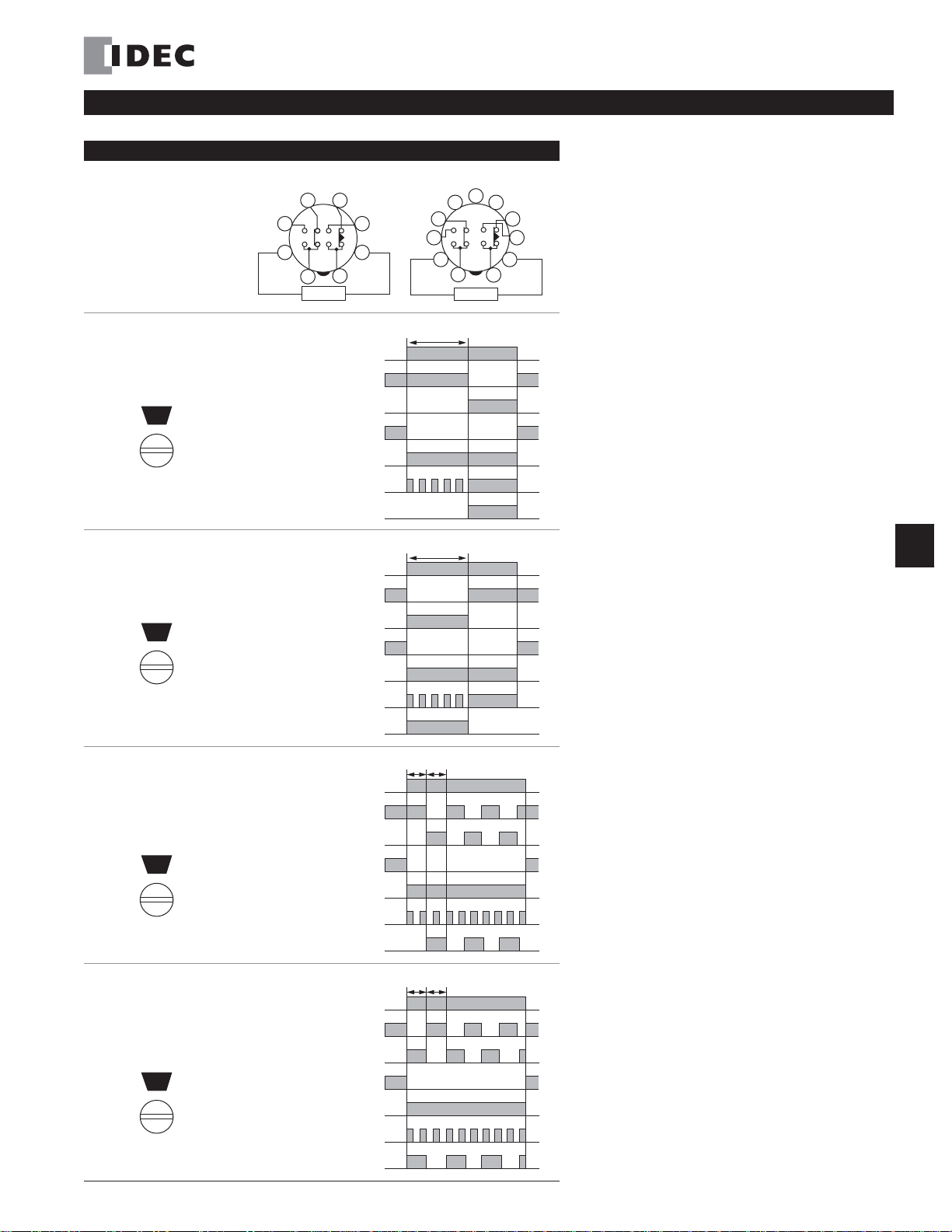
GT3A- 2 Timing Diagrams
Delayed SPDT + Instantaneous SPDT
Operation
Mode Selection
ON-Delay 1
MODE
A
Interval 1
MODE
B
8-Pin
Item
Power
Delayed
Contact
Instantaneous
Contact
Indicator
Item
Power
Delayed
Contact
Instantaneous
Contact
5
4
3
2
8
1
POWER
Terminal No. Operation
2-7 (8p)
(Power)
2-10 (11p)
5-8 (8p)
(NC)
8-11 (11p)
6-8 (8p)
(NO)
9-11 (11p)
1-4
(NC)
1-3
(NO)
POWER
OUT
Terminal No. Operation
2-7 (8p)
(Power)
2-10 (11p)
5-8 (8p)
(NC)
8-11 (11p)
6-8 (8p)
(NO)
9-11 (11p)
1-4
(NC)
1-3
(NO)
11-Pin
6
7
(+)(-)
Set Time
Set Time
6
57
3
2
1
POWER
84
9
10
(+)(-)
11
G
Timers
Cycle 1
(OFF first)
Cycle 3
(ON first)
MODE
C
MODE
D
Indicator
Item
Power
Delayed
Contact
Instantaneous
Contact
Indicator
Item
Power
Delayed
Contact
Instantaneous
Contact
Indicator
POWER
OUT
Terminal No. Operation
2-7 (8p)
(Power)
2-10 (11p)
5-8 (8p)
(NC)
8-11 (11p)
6-8 (8p)
(NO)
9-11 (11p)
1-4
(NC)
1-3
(NO)
POWER
OUT
Terminal No. Operation
2-7 (8p)
(Power)
2-10 (11p)
5-8 (8p)
(NC)
8-11 (11p)
6-8 (8p)
(NO)
9-11 (11p)
1-4
(NC)
1-3
(NO)
POWER
OUT
Set Time
Set Time
www.idec.com USA: (800) 262-IDEC or (408) 747-0550, Canada: (888) 317-IDEC G-17
Page 5
GT3A Series Timers
GT3A-3 Timing Diagrams
Delayed DPDT
G
Timers
Operation
Mode Selection
ON-Delay 1
MODE
A
Interval 1
MODE
B
8-Pin
Item
Power
Delayed
Contact
Indicator
Item
Power
Delayed
Contact
Indicator
5
4
3
2
8
1
POWER
Terminal No. Operation
2-7 (8p)
(Power)
2-10 (11p)
1-4, 5-8 (8p)
(NC)
1-4, 8 -11(11p)
1-3, 6-8 (8p)
(NO)
1-3, 9-11(11p)
POWER
OUT
Terminal No. Operation
2-7 (8p)
(Power)
2-10 (11p)
1-4, 5-8 (8p)
(NC)
1-4, 8 -11(11p)
1-3, 6-8 (8p)
(NO)
1-3, 9-11(11p)
POWER
OUT
11-Pin
6
7
(+)(-)
Set Time
Set Time
6
57
3
2
1
POWER
84
9
10
(+)(-)
11
Cycle 1
(OFF first)
Cycle 3
(ON first)
MODE
C
MODE
D
Item
Power
Delayed
Contact
Indicator
Item
Power
Delayed
Contact
Indicator
Terminal No. Operation
2-7 (8p)
(Power)
2-10 (11p)
1-4, 5-8 (8p)
(NC)
1-4, 8 -11(11p)
1-3, 6-8 (8p)
(NO)
1-3, 9-11(11p)
POWER
OUT
Terminal No. Operation
2-7 (8p)
(Power)
2-10 (11p)
1-4, 5-8 (8p)
(NC)
1-4, 8 -11(11p)
1-3, 6-8 (8p)
(NO)
1-3, 9-11(11p)
POWER
OUT
Set Time
Set Time
G-18 www.idec.com USA: (800) 262-IDEC or (408) 747-0550, Canada: (888) 317-IDEC
Page 6
Operation
2-10 (POWER)
2-6 (A)
5-7 (B)
ON or L
2-7 (A)
6-7 (B)
ON or L
2-5 (A) ON or L
1-4
8-11
(NC)
1-3
9-11
(NO)
POWER
OUT
Set Time
Indicator
Delayed
Contact
Input
Start
Reset
Gate
Power
Item Terminal No. Operation
T
Ta
T'
T"
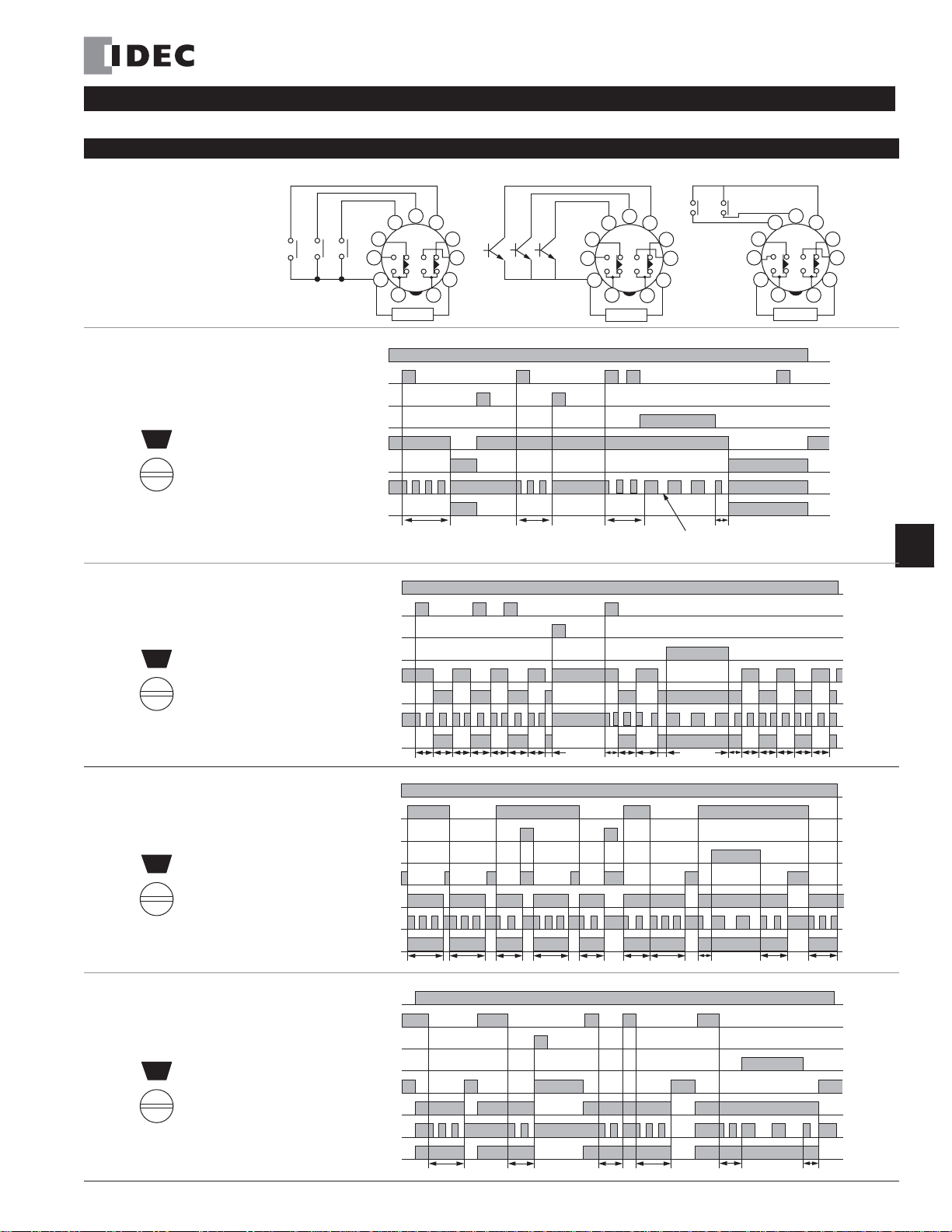
Note: While the gate input is on
during time-delay operation, the
POWER indicator flash rate slows down.
O
It
O
Mode Selection
ON-Delay 2
MODE
A
Timers GT3A Series
GT3A-4 Timing Diagrams
Delayed DPDT
(A Type)
(Contact Input)
ResetStartGate
6
57
3
2
1
POWER
(Transistor Input) (B Type)
6
Reset StartGate
84
9
10
11
(+)(-)
57
3
2
1
POWER
11
Start Reset
84
9
10
(+)(-)
Note: T = Set time
6
57
3
2
1
POWER
Ta = Shorter
than set time
T = T' + T"
84
9
10
11
(+)(-)
Item Terminal No.
Power
Cycle 2
MODE
B
Delayed
Contact
Indicator
Set Time
Power
Signal ON/OFF-Delay 1
MODE
C
Delayed
Contact
Indicator
Set Time
Item Terminal No. Operation
Signal OFF-Delay 1
www.idec.com USA: (800) 262-IDEC or (408) 747-0550, Canada: (888) 317-IDEC G-19
MODE
D
Power
Delayed
Contact
Indicator
Set Time
2-10 (POWER)
2-6 (A)
Start
Reset
Input
Gate
emTerminal No.
Start
Reset
Input
Gate
Start
Reset
Input
Gate
ON or L
5-7 (B)
2-7 (A)
ON or L
6-7 (B)
2-5 (A) ON or L
1-4
(NC)
8-11
1-3
(NO)
9-11
POWER
OUT
2-10 (POWER)
2-6 (A)
ON or L
5-7 (B)
2-7 (A)
ON or L
6-7 (B)
2-5 (A) ON or L
1-4
(NC)
8-11
1-3
(NO)
9-11
POWER
OUT
2-10 (POWER)
2-6 (A)
ON or L
5-7 (B)
2-7 (A)
ON or L
6-7 (B)
2-5 (A) ON or L
1-4
(NC)
8-11
1-3
(NO)
9-11
POWER
OUT
T T T T
T
T T
T Ta T Ta T T
T
T Ta
Ta
peration
T T T
peration
Ta T
T’
T T’’ Ta
T T T T T
T’’
T’ Ta
G
Timers
Page 7
GT3A Series Timers
2
6
57
84
3
POWER
(+)(-)
9
10
11
1
ResetStartGate
2
6
57
84
3
POWER
(+)(-)
9
10
11
1
Reset StartGate
2
6
57
84
3
POWER
(+)(-)
9
10
11
1
Start Reset
(A Type)
(Contact Input) (Transistor Input)
(B Type)
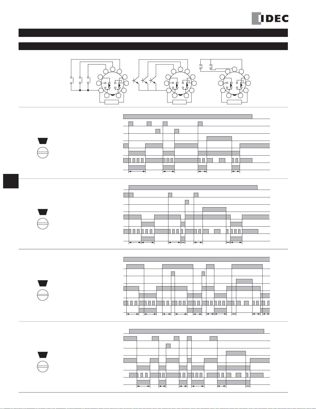
Note: T = Set time
Ta = Shorter
T = T’ + T”
than set time
GT3A- 5 Timing Diagrams
.
Delayed DPDT
Operation
Mode Selection
Item Terminal No. Operation
Power
Interval 2
MODE
A
Delayed
Contact
Indicator
Set Time
G
Item Terminal No. Operation
Power
One-Shot Cycle
MODE
Timers
B
Delayed
Contact
Indicator
Set Time
Item Terminal No. Operation
Power
Signal ON/OFF-Delay 2
MODE
C
Delayed
Contact
Indicator
Set Time
Item Terminal No. Operation
Power
Signal OFF-Delay 2
MODE
G-20 www.idec.com USA: (800) 262-IDEC or (408) 747-0550, Canada: (888) 317-IDEC
D
Delayed
Contact
Indicator
Set Time
Start
Reset
Input
Gate
Start
Reset
Input
Gate
Start
Reset
Input
Gate
Start
Reset
Input
Gate
2-10 (POWER)
2-6 (A)
ON or L
5-7 (B)
2-7 (A)
ON or L
6-7 (B)
2-5 (A) ON or L
1-4
(NC)
8-11
1-3
(NO)
9-11
POWER
OUT
2-10 (POWER)
2-6 (A)
ON or L
5-7 (B)
2-7 (A)
ON or L
6-7 (B)
2-5 (A) ON or L
1-4
(NC)
8-11
1-3
(NO)
9-11
POWER
OUT
2-10 (POWER)
2-6 (A)
ON or L
5-7 (B)
2-7 (A)
ON or L
6-7 (B)
2-5 (A) ON or L
1-4
(NC)
8-11
1-3
(NO)
9-11
POWER
OUT
2-10 (POWER)
2-6 (A)
ON or L
5-7 (B)
2-7 (A)
ON or L
6-7 (B)
2-5 (A) ON or L
1-4
(NC)
8-11
1-3
(NO)
9-11
POWER
OUT
T Ta T'
T T T'
T Ta
T T Ta
T Ta
T TTa
Ta
Ta T' T" Ta
T"
T
T"
T
T'
T"
Page 8
Timers GT3A Series
2
6
57
84
3
POWER
(+)(-)
9
10
11
1
ResetStartGate
2
6
57
84
3
POWER
(+)(-)
9
10
11
1
Reset StartGate
2
6
57
84
3
POWER
(+)(-)
9
10
11
1
Start Reset
(A Type)
(Contact Input) (Transistor Input)
(B Type)
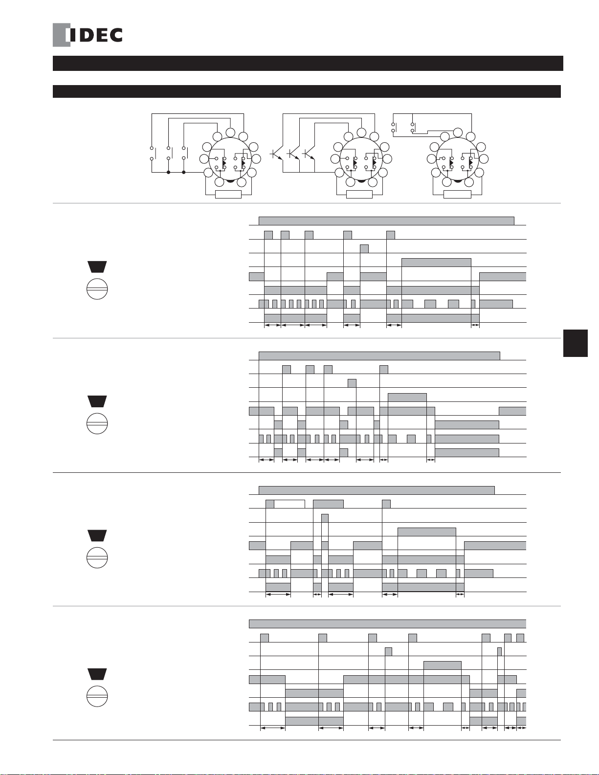
Note: T = Set time
Ta = Shorter
T = T' + T"
than set time
Operation
Mode Selection
Item Terminal No. Operation
Power
One-Shot 1
MODE
A
One-Shot ON-Delay
MODE
B
One Shot 2
MODE
C
Signal
ON/OFF-Delay 3
MODE
www.idec.com USA: (800) 262-IDEC or (408) 747-0550, Canada: (888) 317-IDEC G-21
D
Start
Reset
Input
Gate
Delayed
Contact
Indicator
Set Time
Item Terminal No. Operation
Power
Start
Reset
Input
Gate
Delayed
Contact
Indicator
Set Time
Item Terminal No. Operation
Power
Start
Reset
Input
Gate
Delayed
Contact
Indicator
Set Time
Item Terminal No. Operation
Power
Start
Reset
Input
Gate
Delayed
Contact
Indicator
Set Time
2-10 (POWER)
2-6 (A)
ON or L
5-7 (B)
2-7 (A)
ON or L
6-7 (B)
2-5 (A) ON or L
1-4
(NC)
8-11
1-3
(NO)
9-11
POWER
OUT
2-10 (POWER)
2-6 (A)
ON or L
5-7 (B)
2-7 (A)
ON or L
6-7 (B)
2-5 (A) ON or L
1-4
(NC)
8-11
1-3
(NO)
9-11
POWER
OUT
2-10 (POWER)
2-6 (A)
ON or L
5-7 (B)
2-7 (A)
ON or L
6-7 (B)
2-5 (A) ON or L
1-4
(NC)
8-11
1-3
(NO)
9-11
POWER
OUT
2-10 (POWER)
2-6 (A)
ON or L
5-7 (B)
2-7 (A)
ON or L
6-7 (B)
2-5 (A) ON or L
1-4
(NC)
8-11
1-3
(NO)
9-11
POWER
OUT
GT3A- 6 Timing Diagrams
Delayed DPDT
Ta T'TaT
Ta
T T'TTaT T T"
T T'TTa
T TaT
T"
G
Timers
T"
T' T"’ Ta Ta T
Page 9
GT3A Series Timers
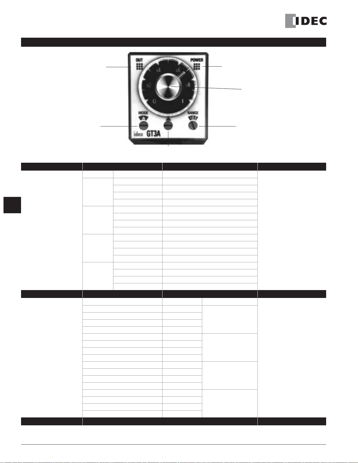
Instructions: Setting GT3A Series Timers
G
Select the desired mode
of operation.
Timers
Select the time range
that contains the desired
time period.
Timed OUT Indicator
POWER Indicator
(flashes during
time-delay period)
➃ Setting Knob
➀ Operation Mode
Selector
A, B, C, D
➁ Dial Selector
0-1, 0-3, 0-6, 0-18
Step 1. Desired Mode of Operation Selection Remarks
For Timers Mode of Operation ➀ Operation Mode Selector
ON-delay 1 A
GT3A-1
GT3A-2
GT3A-3
GT3A-4
GT3A-5
GT3A-6
Interval 1 B
Cycle 1 C
Cycle 3 D
ON-delay 2 A
Cycle 2 B
Signal ON/OFF-delay 1 C
Signal OFF-delay 1 D
Interval 2 A
One-shot cycle B
Signal ON/OFF-delay 2 C
Signal OFF-delay 2 D
One-shot 1 A
One-shot ON-delay B
One-shot 2 C
Signal ON/OFF-delay 3 D
Step 2. Desired Time Range Selection Remarks
Time Ranges ➁ Dial Selector ➂Time Range Selector
0.05 seconds to 1 second 0-1
0.05 seconds to 3 seconds 0-3
0.05 seconds to 6 seconds 0-6
0.15 seconds to 18 seconds 0-18
0.1 seconds to 10 seconds 0-1
0.3 seconds to 30 seconds 0-3
0.6 seconds to 60 seconds 0-6
1.8 seconds to 180 seconds 0-18
6 seconds to 10 minutes 0-1
18 seconds to 30 minutes 0-3
36 seconds to 60 minutes 0-6
108 seconds to 180 minutes 0-18
6 minutes to 10 hours 0-1
18 minutes to 30 hours 0-3
36 minutes to 60 hours 0-6
108 minutes to 180 hours 0-18
Step 3. Selection
➂ Time Range Selector
1S, 10S, 10M, 10H
1S
10S
10M
10H
The desired operation mode
can be selected from the A, B,
C, and D modes using the Operation Mode Selector. Change
the operation mode from A to
B, C, and D in turn by turning
the operation mode selector
clockwise using a flat screwdriver which is a maximum of
0.156” (4mm) wide. The
selected mode is displayed
in the window.
The desired time range is
selected by setting both
➁ Dial Selector and
➂ Time Range Selector.
A
Set the precise period of time desired by using the ➃ Setting Knob.
G-22 www.idec.com USA: (800) 262-IDEC or (408) 747-0550, Canada: (888) 317-IDEC
Page 10
Timers
Operation System
Operation
Time Range
Rated Voltage
Contact Ratings
Contact Form
Minimum Applicable Load
Voltage Tolerance
Error
Setting Error
Reset Time
Insulation Resistance
Dielectric Strength
Power
Specifications
Consumption
(approximate)
Mechanical Life
Electrical Life (at rated load)
Outputs Relay
Vibration Resistance
Shock Resistance
Operating Temperature
Storage Temperature
Operating Humidity
Weight (approximate)
Housing Color
AF20
AD24 AC/DC
GT3D Series — Digital Timers
Key features of the GT3D series include:
• Precise time setting using digital thumbwheel switches
• Elapsed or time remaining LED display
•6 time ranges, 16 timing functions
•Time delays up to 99.9 hours
UL Recognized
File No.E55996
GT3D-2 GT3D-3 GT3D-4 GT3D-8
Solid state CMOS circuitry
Multi-mode
0.01s to 99.9 hours
100 to 240V AC (50/60Hz), 24V AC (50/60Hz)/24V DC
125V AC/250V AC, 3A;
30V DC/1A (resistive load)
Delayed SPDT +
instantaneous SPDT
±0.3% ±50ms (voltage, repeat, and temperature)
Between power and output terminals: 2,000V AC, 1 minute
Between contacts of different poles: 2,000V AC, 1 minute
Between contacts of the same pole: 750V AC, 1 minute
11.8VA 11.6VA
1VA/0.8W 2.1VA/0.9W 2.1VA /0.9W
10,000,000 operations
minimum
50,000 operations mini-
mum
250V AC, 3A, 30V DC, 1A
(resistive load)
Operating extremes: 100N (approximate 10G)
70g 75g 76g
Delayed DPDT Delayed DPDT Delayed DPDT
5V, 10mA (reference value)
AF20 (100–240V AC): 85 to 264V AC
AD24 (AC): 20.4 to 26.4V AC
AD24 (DC): 21.6 to 26.4V DC
±0.5% ±50ms
60ms maximum
100M
100N (approximate 10G)
Damage limits: 500N (approximate 50G)
–10 to +50°C
–30 to +80°C
45 to 85% RH
125V AC/250V AC, 5A;
30V DC/5A (resistive load)
Ω
minimum
5,000,000 operations minimum
100,000 operations minimum
240V AC/, 24V DC, 5A
Gray
CSA Certified
File No.LR58183
LR96764
LR83814
3.7VA (100V AC, 60Hz)
11.6VA (200V AC, 60Hz)
(resistive load)
Multi-mode.
one-shot output
GT3D Series
Cert. No.
BL9801133323911 (LVD)
E9971113332388 (EMC)
G
Timers
GT3D Table of Contents
Specifications — G-23
Part Number List — G-24
Timing Diagrams/
Schematics — G-25
Instructions:
Setting Timer — G-33
GT3 Accessories — G-48
GT3 Instructions:
Wiring Inputs — G-50
GT3 Dimensions — G-52
Timing Diagrams
Overview — G-4
www.idec.com
USA: (800) 262-IDEC or (408) 747-0550, Canada: (888) 317-IDEC G-23
Page 11
GT3D Series
Part Numbers: GT3D-1/GT3D-2/GT3D-3
Mode of Operation
1-A: ON-delay 1
1-B: Interval 1 first
1-C: Cycle 1 (OFF first)
1-D: Cycle 3 (ON first)
Part Numbers: GT3D-4
Mode of Operation
1-A: ON-delay 1
1-B: Interval 1 first
1-C: Cycle 1 (OFF first)
1-D: Cycle 3 (ON first)
2-A: ON-delay 2
2-B: Cycle 2
2-C: Signal ON/OFF-delay 1
2-D: Signal OFF-delay 1
2-E: Interval 2
2-F: One-shot cycle
3-A: Signal ON/OFF-delay 2
3-B: Signal OFF-delay 2
3-C: One-shot 1
3-D: One-shot ON-delay
G
3-E: One-shot 2
3-F: Signal ON/OFF-delay 3
Time
Range
0.01s to
99.9
hours
Time
Range
0.01s to
99.9
hours
Part Number List
Output Contact Rated Voltage Code
250V AC, 3A,
30V DC, 1A
(resistive load)
240V AC/,
24V DC, 5A
(resistive load)
Delayed SPDT
+ instantaneous SPDT
Delayed DPDT
100 to 240V AC (50/60Hz) GT3D-2AF20 GT3D-2EAF20
24V AC/DC GT3D-2AD24 —
100 to 240V AC (50/60Hz) GT3D-3AF20 GT3D-3EAF20
24V AC/DC GT3D-3AD24 —
Output Contact Rated Voltage Code
100 to 240V AC (50/60Hz)
240V AC/24V DC,
5A
(resistive load)
Delayed DPDT
24V AC/DC GT3D-4AD24 —
Timers
Complete Part No.
8-Pin 11-Pin
Complete Part No.
A (11-pin) B (11-pin)
GT3D-4AF20 GT3D-4EAF20
Part Numbers: GT3D-8
Mode of
Timers
Operation
1: ON-delay one-shot 1
2: Cycle one-shot
3: ON-delay one-shot 2
1. For wiring schematics and timing diagrams GT3D, see pages G-25 to G-32.
2. For more details about time ranges, see instructions on page G-33.
3. A (11-pin) and B (11-pin) differ in the way inputs are wired.
4. For socket and accessory part numbers, see page G-48.
5. For timing diagrams overview, see page G-4.
Time
Range
0.01s to
99.9
hours
Output Contact Rated Voltage Code Complete Part No. (11-pin)
240V AC/24V DC,
5A
(resistive load)
Delayed DPDT
100 to 240V AC (50/60Hz) GT3D-8AF20
24V AC/DC GT3D-8AD24
G-24
www.idec.com
USA: (800) 262-IDEC or (408) 747-0550, Canada: (888) 317-IDEC
Page 12
It
T
O
O
Contact
ON-Delay 1
Time Remaining
1 A
Time Elapsed
Timers
GT3D Series
GT3D-2 Timing Diagrams
Delayed SPDT + Instantaneous SPDT
8-Pin
3
2
Item
Power
Delayed
Contact
—
A1—
Instantaneous
Contact
Indicator
Digital
Time
Display
5
4
6
7
8
1
POWER
Terminal No. Operation
2-7 (8p)
(Power)
2-10 (11p)
1-4, 5-8 (8p)
(NC)
1-4, 8-11 (11p)
1-3, 6-8 (8p)
(NO)
1-3, 9-11 (11p)
1-4
(NC)
1-3
(NO)
OUT
DOWN
UP
11-Pin
(+)(-)
57
3
2
1
POWER
Set Time
6
84
9
10
(+)(-)
11
em
Power
Interval 1
Time Remaining
1 B
—
Time Elapsed
B1—
Cycle 1 (OFF first)
Time Remaining
1 C
—
Time Elapsed
C1—
Cycle 3 (ON first)
Time Remaining
1 D
Time Elapsed
—
D1—
Delayed
Contact
Instantaneous
Contact
Indicator
Digital
Time
Display
Item
Power
Delayed
Contact
Instantaneous
Contact
Indicator
Digital
Time
Display
Item
Power
Delayed
Contact
Instantaneous
Contact
Indicator
Digital
Time
Display
erminal No.
2-7 (8p)
(Power)
2-10 (11p)
1-4, 5-8 (8p)
(NC)
1-4, 8-11 (11p)
1-3, 6-8 (8p)
(NO)
1-3, 9-11 (11p)
1-4
(NC)
1-3
(NO)
OUT
DOWN
UP
Terminal No.
2-7 (8p)
(Power)
2-10 (11p)
1-4, 5-8 (8p)
(NC)
1-4, 8-11 (11p)
1-3, 6-8 (8p)
(NO)
1-3, 9-11 (11p)
1-4
(NC)
1-3
(NO)
OUT
DOWN
UP
Terminal No. Operation
2-7 (8p)
(Power)
2-10 (11p)
1-4, 5-8 (8p)
(NC)
1-4, 8-11 (11p)
1-3, 6-8 (8p)
(NO)
1-3, 9-11 (11p)
1-4
(NC)
1-3
(NO)
OUT
DOWN
UP
Set Time
Set Time
peration
Set Time
peration
G
Timers
www.idec.com
USA: (800) 262-IDEC or (408) 747-0550, Canada: (888) 317-IDEC G-25
Page 13
GT3D Series
Contact
Operation
Mode Selection
ON-Delay 1
Time Remaining
1 A
—
Time Elapsed
Timers
GT3D-3 Timing Diagrams
Delayed DPDT
8-Pin
3
2
Item
Power
Delayed
Contact
Indicator
A1—
Digital
Time
Display
5
4
6
7
8
1
POWER
Terminal No. Operation
2-7 (8p)
(Power)
2-10 (11p)
1-4, 5-8 (8p)
(NC)
1-4, 8-11 (11p)
1-3, 6-8 (8p)
(NO)
1-3, 9-11 (11p)
OUT
DOWN
UP
11-Pin
(+)(-)
Set Time
6
57
3
2
1
POWER
84
9
10
(+)(-)
11
G
Interval 1
Timers
Cycle 1 (OFF first)
Cycle 3 (ON first)
Time Remaining
1 B
—
Time Elapsed
B1—
Time Remaining
1 C
—
Time Elapsed
C1—
Time Remaining
1 D
—
Time Elapsed
D1—
Item
Power
Delayed
Contact
Indicator
Digital
Time
Display
Item
Power
Delayed
Contact
Indicator
Digital
Time
Display
Item
Power
Delayed
Contact
Indicator
Digital
Time
Display
Terminal No. Operation
2-7 (8p)
(Power)
2-10 (11p)
1-4, 5-8 (8p)
(NC)
1-4, 8-11 (11p)
1-3, 6-8 (8p)
(NO)
1-3, 9-11 (11p)
OUT
DOWN
UP
Terminal No. Operation
2-7 (8p)
(Power)
2-10 (11p)
1-4, 5-8 (8p)
(NC)
1-4, 8-11 (11p)
1-3, 6-8 (8p)
(NO)
1-3, 9-11 (11p)
OUT
DOWN
UP
Terminal No. Operation
(NC)
(NO)
2-7 (8p)
2-10 (11p)
1-4, 5-8 (8p)
1-4, 8-11 (11p)
1-3, 6-8 (8p)
1-3, 9-11 (11p)
OUT
DOWN
UP
(Power)
Set Time
Set Time
Set Time
G-26
www.idec.com
USA: (800) 262-IDEC or (408) 747-0550, Canada: (888) 317-IDEC
Page 14

Timers
GT3D Series
GT3D-4 Timing Diagrams
These timers require a start input. A gate and reset input are optional. Inputs are controlled by external pushbuttons. Reset occurs when the power is removed or
when the reset input is supplied. The gate signal can be used to interrupt (freeze) timer functions. Timer functions resume when the gate input is removed. B style
timers are not equipped for gate input.
GT3D-4
Delayed DPDT
(A Type)
(Contact Input) (Transistor Input)
StartGate
Reset
(B Type)
(Contact Input)
Start Reset
3
2
6
57
3
2
1
11
POWER
6
57
84
9
1
POWER
10
11
(+)(-)
Reset StartGate
84
9
10
(+)(-)
(Transistor Input)
Start Reset
3
2
6
57
3
2
1
11
POWER
6
57
84
9
1
POWER
10
11
(+)(-)
84
9
10
(+)(-)
G
Timers
ON-Delay 1
Time Remaining
1 A
—
Time Elapsed
A1—
Interval 1
Time Remaining
1 B
—
Time Elapsed
B1—
Item
Power
Delayed
Contact
Indicator
Digital
Time
Display
Set Time
Item
Power
Delayed
Contact
Indicator
Digital
Time
Display
Set Time
Terminal No. Operation
GT3D-4
2-10 (POWER)
1-4
(NC)
(NO)
(NC)
(NO)
8-11
8-11
1-3
9-11
9-11
OUT
DOWN
UP
T
Terminal No. Operation
GT3D-4
2-10 (POWER)
1-4
8-11
8-11
1-3
9-11
9-11
OUT
DOWN
UP
T
www.idec.com
USA: (800) 262-IDEC or (408) 747-0550, Canada: (888) 317-IDEC G-27
Page 15

g
GT3D Series
Cycle 1 (OFF first)
Cycle 3 (ON first)
G
Time Remainin
1 C
—
Time Elapsed
C1—
Time Remaining
1 D
—
Time Elapsed
D1—
Item
Power
Delayed
Contact
Indicator
Digital
Time
Display
Set Time
Item
Power
Delayed
Contact
Indicator
Digital
Time
Display
Set Time
GT3D-4 Timing Diagrams, continued
Terminal No. Operation
GT3D-4
2-10 (POWER)
1-4
(NC)
(NO)
(NC)
(NO)
8-11
8-11
1-3
9-11
9-11
OUT
DOWN
UP
T
T T T T
Terminal No. Operation
GT3D-4
2-10 (POWER)
1-4
8-11
8-11
1-3
9-11
9-11
OUT
DOWN
UP
T T T T
T
Timers
T
T
Timers
ON-Delay 2
Time Remaining
2 A
—
Time Elapsed
A2—
Item
Power
Start
Reset
Input
Gate
Delayed
Contact
Indicator
Digital
Time
Display
Set Time
Terminal No. Operation
GT3D-4
2-10 (POWER)
2-6 (A)
3-6ON or L
5-7 (B)
2-7 (A)
3-7ON or L
6-7 (B)
2-5 (A) 3-5ON or L
1-4
(NC)
(NO)
8-11
1-3
9-11
OUT
DOWN
UP
8-11
9-11
T
Ta
T’
T’
G-28
www.idec.com
USA: (800) 262-IDEC or (408) 747-0550, Canada: (888) 317-IDEC
Page 16

2 B
B2—
—
Time Remaining
Time Elapsed
2 C
C2—
—
Time Remaining
Time Elapsed
Item
Power
Delayed
Indicator
Terminal No. Operation
2-10 (POWER)
8-11
8-11
9-11
UP
Contact
OUT
DOWN
Digital
Time
Display
1-4
1-3
Set Time
GT3D-4
9-11
(NC)
(NO)
2-6 (A)
5-7 (B)
3-6ON or L
2-7 (A)
6-7 (B)
3-7ON or L
2-5 (A) 3-5ON or L
Start
Reset
Gate
Input
T TTa Ta T T’T Ta T’’ Ta
2 D
D2—
—
Time Remaining
Time Elapsed
Item
Power
Delayed
Indicator
Terminal No. Operation
2-10 (POWER)
8-11
8-11
9-11
UP
Contact
OUT
DOWN
Digital
Time
Display
1-4
1-3
Set Time
GT3D-4
9-11
(NC)
(NO)
2-6 (A)
5-7 (B)
3-6ON or L
2-7 (A)
6-7 (B)
3-7ON or L
2-5 (A) 3-5ON or L
Start
Reset
Gate
Input
Ta Ta TT T’ T’’
2 E
E2—
—
Time Remaining
Time Elapsed
Item
Power
Delayed
Indicator
Terminal No. Operation
2-10 (POWER)
8-11
8-11
9-11
UP
Contact
OUT
DOWN
Digital
Time
Display
1-4
1-3
Set Time
GT3D-4
9-11
(NC)
(NO)
2-6 (A)
5-7 (B)
3-6ON or L
2-7 (A)
6-7 (B)
3-7ON or L
2-5 (A) 3-5ON or L
Start
Reset
Gate
Input
Ta T’T T’’
Cycle 2
Signal ON/OFF-Delay 1
Timers
Set Time
Item
Power
Start
Reset
Input
Gate
Delayed
Contact
Indicator
Digital
Time
Display
GT3D-4 Timing Diagrams, continued
Terminal No. Operation
GT3D-4
2-10 (POWER)
2-6 (A)
3-6ON or L
5-7 (B)
2-7 (A)
3-7ON or L
6-7 (B)
2-5 (A) 3-5ON or L
1-4
(NC)
(NO)
8-11
1-3
9-11
OUT
DOWN
UP
8-11
9-11
T T T T T T T T T T T’ T’’ T T
T
Ta
GT3D Series
Signal OFF-Delay 1
Interval 2
www.idec.com
USA: (800) 262-IDEC or (408) 747-0550, Canada: (888) 317-IDEC G-29
G
Timers
Page 17

GT3D Series Timers
O
O
O
O
GT3D-4 Timing Diagrams, continued
One-Shot Cycle
Time Remaining
2 F
Time Elapsed
Signal ON/OFF-Delay 2
Time Remaining
3 A
G
Time Elapsed
Timers
Signal OFF-Delay 2
Time Remaining
3 B
Time Elapsed
One-Shot 1
Time Remaining
3 C
Time Elapsed
Item
Power
Start
Reset
Input
Gate
—
F2—
—
A3—
—
B3—
—
C3—
Delayed
Contact
Indicator
Digital
Time
Display
Set Time
Item
Power
Start
Reset
Input
Gate
Delayed
Contact
Indicator
Digital
Time
Display
Set Time
Item
Power
Start
Reset
Input
Gate
Delayed
Contact
Indicator
Digital
Time
Display
Set Time
Item
Power
Start
Reset
Input
Gate
Delayed
Contact
Indicator
Digital
Time
Display
Set Time
Terminal No.
GT3D-4
2-10 (POWER)
2-6 (A)
5-7 (B)
2-7 (A)
6-7 (B)
2-5 (A) 3-5ON or L
1-4
(NC)
8-11
1-3
(NO)
9-11
OUT
DOWN
UP
Terminal No.
GT3D-4
2-10 (POWER)
2-6 (A)
5-7 (B)
2-7 (A)
6-7 (B)
2-5 (A) 3-5ON or L
1-4
(NC)
8-11
1-3
(NO)
9-11
OUT
DOWN
UP
Terminal No.
GT3D-4
2-10 (POWER)
2-6 (A)
5-7 (B)
2-7 (A)
6-7 (B)
2-5 (A) 3-5ON or L
1-4
(NC)
8-11
1-3
(NO)
9-11
OUT
DOWN
UP
Terminal No.
GT3D-4
2-10 (POWER)
2-6 (A)
5-7 (B)
2-7 (A)
6-7 (B)
2-5 (A) 3-5ON or L
1-4
(NC)
8-11
1-3
(NO)
9-11
OUT
DOWN
UP
peration
3-6ON or L
3-7ON or L
8-11
9-11
T TaT T’T T’’ T
peration
3-6ON or L
3-7ON or L
8-11
9-11
TaT
T
3-6ON or L
3-7ON or L
8-11
9-11
T
3-6ON or L
3-7ON or L
8-11
9-11
TaTa TaT T’ T’’
T
Ta
Ta T T’ T’’
TaTa T T’ T’’ T
peration
peration
G-30 www.idec.com USA: (800) 262-IDEC or (408) 747-0550, Canada: (888) 317-IDEC
Page 18

One-Shot ON-Delay
Item
Power
Delayed
Indicator
Terminal No. Operation
2-10 (POWER)
8-11
8-11
9-11
UP
Contact
OUT
DOWN
Digital
Time
Display
1-4
1-3
Set Time
GT3D-4
9-11
(NC)
(NO)
2-6 (A)
5-7 (B)
3-6ON or L
2-7 (A)
6-7 (B)
3-7ON or L
2-5 (A) 3-5ON or L
Start
Reset
Gate
Input
TT TTa T T’ T’’
Item
Power
Delayed
Indicator
Terminal No. Operation
2-10 (POWER)
8-11
8-11
9-11
UP
Contact
OUT
DOWN
Digital
Time
Display
1-4
1-3
Set Time
GT3D-4
9-11
(NC)
(NO)
2-6 (A)
5-7 (B)
3-6ON or L
2-7 (A)
6-7 (B)
3-7ON or L
2-5 (A) 3-5ON or L
Start
Reset
Gate
Input
T TTa T’ T’’
Item
Power
Delayed
Indicator
Terminal No. Operation
2-10 (POWER)
8-11
8-11
9-11
UP
Contact
OUT
DOWN
Digital
Time
Display
1-4
1-3
Set Time
GT3D-4
9-11
(NC)
(NO)
2-6 (A)
5-7 (B)
3-6ON or L
2-7 (A)
6-7 (B)
3-7ON or L
2-5 (A) 3-5ON or L
Start
Reset
Gate
Input
T T Ta T’ T’’ TaTaTa
Time Remaining
3 D
—
Time Elapsed
D3—
Timers GT3D Series
GT3D-4 Timing Diagrams, continued
One Shot 2
Time Remaining
3 E
—
Time Elapsed
E3—
Signal ON/OFF-Delay 3
Time Remaining
3 F
—
Time Elapsed
F3—
G
Timers
www.idec.com USA: (800) 262-IDEC or (408) 747-0550, Canada: (888) 317-IDEC G-31
Page 19

GT3D Series Timers
GT3D-8 Timing Diagrams
Delayed DPDT
ON-Delay One-Shot 1
Time Remaining
Time Elapsed
G
Timers
Cycle One-Shot
Time Remaining
Time Elapsed
(Contact Input)
6
57
Reset
StartGate
3
2
1
POWER
Item
Power
Input
1
1
2
2
Delayed
Contact
Indicator
Digital
Time
Display
Set Time
Item
Power
Delayed
Contact
Indicator
Digital
Time
Display
Set Time
Item
Terminal No. Operation
2-10 (POWER)
Start
Reset
Gate
1-4
(NC)
8-11
1-3
(NO)
9-11
OUT
DOWN
UP
Terminal No. Operation
2-10 (POWER)
Start
Reset
Input
Gate
1-4
(NC)
8-11
1-3
(NO)
9-11
OUT
DOWN
UP
Terminal No. Operation
84
9
10
11
(+)(-)
2-6ON or L
2-7ON or L
2-5ON or L
2-6ON or L
2-7ON or L
2-5ON or L
(Transistor Input)
Reset StartGate
To
T
T
ToTTo
Note: T = Set time
6
57
84
3
2
1
POWER
Ta T T’’ ToTb T’ T Tb
Ta TbT T
T
9
10
11
(+)(-)
T’
To
Ta = Shorter than set time
Tb = Shorter than single-shot
output time
T = T’ + T”
T0 = Single-shot output time
(selected from
A, B, C, D, E or F)
T’’
Ta
ToTo
ON-Delay One-Shot 2
Time Remaining
Time Elapsed
Power
3
3
Delayed
Contact
Indicator
Digital
Time
Display
Set Time
Start
Reset
Input
Gate
2-10 (POWER)
2-6ON or L
2-7ON or L
2-5ON or L
1-4
(NC)
8-11
1-3
(NO)
9-11
OUT
DOWN
UP
To
T Ta
T
Tb
Ta T’
T Tb
Tb
T’’
G-32 www.idec.com USA: (800) 262-IDEC or (408) 747-0550, Canada: (888) 317-IDEC
Page 20

Timers GT3D Series
A
B
C
D
S
SMM
H
H
Instructions: Setting GT3D-2, GT3D-3 Timers
Timed OUT Indicator
➃ Time Setting
Digital Time Display
(LCD backlit
with red LED)
Digital Switch
➀ Indication Mode
Selector
1 1
Step 1 Desired Mode/Selection Remarks
Time
Display
Mode
Time
elapsed
Time
remaining
Time
Select the desired
time display and
operation modes.
elapsed
Time
remaining
Time
elapsed
Time
remaining
Time
elapsed
Time
remaining
Step 2 Desired Operation Selection Remarks
Select a time range that
contains the desired
period of time.
0.01 seconds to 9.99 seconds 9.99
0.1 seconds to 99.9 seconds 99.9
1 second to 999 seconds 999
0.1 minutes to 99.9 minutes 99.9
1 minute to 999 minutes 999
0.1 hours to 99.9 hours 99.9
Step 3 Desired Operation Selection Remarks
Set the precise period of time desired by using the
➀ Indicator Mode
Selector
1
1
1
1
1
1
1
1
1
1
1
1
Base Time Ranges
➁ Operation Mode Selector
A, B, C, D
Operation
Mode
ON-delay 1
Interval
Cycle 1
Cycle 3
Mode Selector
A
B
C
D
➂ Time Range
Selector
Decimal Point
Time Increment
Indicator
➃ Time Setting Digital Switch.
➁ Operation
Indicator
➂ Time Range Selector
9.99S – 99.9H
1. Use the flat screwdriver to set the selectors.
Since selectors do not turn all the way around,
both clockwise and counterclockwise rotation
may be necessary.
➀ Indicator Mode Selector determines
2. The
whether the Digital Time Display shows the
time elapsed or time remaining. The
tion Mode Selector determines the desired
operation mode. Decide which display and
mode is desired, then use these two selec-
tors➀➁ to set the operation mode.
3. The ➁ Operation Mode Selector has two
blank modes which are not intended for use.
Always have this selector set to A, B, C, or D.
1. The ➂ Time Range Selector controls both
the decimal point indicator (9.99, 99.9, 999) and
the time increment indicators S (seconds), M
(minutes), and H (hours).
2. Chose which base time range contains the
targeted timer setting. Then use the ➂ Time
Range Selector to set the decimal point indicator and time increment indicator to its corresponding pair of settings.
3. Since these configurations offer a complete
range of settings from 0.01 seconds to 99.9
hours, the setting of 9.99 for minutes and the
9.99 and 999 settings for hours are not listed
and should not be used.
Use the ➃ Time Setting Digital Switch to set
the desired period of time. It is important to
remember that the setting of the ➂ Time
Range Selector determines the units of time
measurement as well as the implied decimal
point location.
➁ Opera-
G
Timers
It is important to remember that the ➂ Time Range Selector not only selects the time range but also influences the interpretation of the Digital Time Display. Changing the ➂ Time Range Selector setting changes the units of time measurement (seconds,
minutes, hours) as well as the decimal point location.
www.idec.com USA: (800) 262-IDEC or (408) 747-0550, Canada: (888) 317-IDEC G-33
Page 21

GT3D Series Timers
SMH
Instructions: Setting GT3D-4 Timers
Timed OUT Indicator
➃ Time Setting
Digital Time Display
(LCD backlit
with Red LED)
Digital Switch
Step 1 Desired Mode/Selection Remarks
Time
Display
Mode
Time
elapsed
Time
Select the desired
G
time display and
operation modes.
Timers
remaining
Time
elapsed
Time
remaining
Time
elapsed
Time
remaining
Step 2 Desired Operation Selection Remarks
Select a time range that
contains the desired
period of time.
0.01 seconds to 9.99 seconds 9.99
0.1 seconds to 99.9 seconds 99.9
1 seconds to 999 seconds 999
0.1 minutes to 99.9 minutes 99.9
1 minute to 999 minutes 999
0.1 hours to 99.9 hours 99.9
Step 3 Desired Operation Selection Remarks
Select the desired period of time by using the
➀ Operation Mode
Selector/Indication
Mode Selector
➀ Indicator
Mode
Selector
1
1
2
2
3
3
Base Time Ranges
➃Time Setting Digital Switch.
➁ Operation Mode Selector
A, B, C, D, E, F
Operation
Mode
ON-delay 1
Interval 1
Cycle 1
D: Cycle 3
ON-delay 2
Cycle 2
Signal ON/OFF-delay 2
Signal OFF-delay 1
Interval 2
One-shot cycle
Signal ON/OFF-delay 2
Signal OFF-delay 2
One-shot 1
One-shot ON-delay
One-shot 2
Signal ON/OFF-delay 3
➂ Time Range
Decimal Point
Indicator
➁ Operation Mode
A
B
C
D
A
B
C
D
E
F
A
B
C
D
E
F
Selector
Time Increment
➂ Time Range Selector
9.99S – 99.9H
Selector
Indicator
1. Use a flat screwdriver to set the selectors. Since selectors do not turn all the
way around, both clockwise and counterclockwise rotation is necessary.
➀ Indicator Mode Selector deter-
2. The
mines whether the Digital Time Display
shows the time elapsed or time remaining.
➁ Operation Mode Selector deter-
The
mines the desired operation mode. Decide
which display and mode is desired; then
use these two selectors➀➁ to set the
operation mode.
3. When using the indicator mode setting
“1,” the ➁ Operation Mode Selector has
two blank modes which are not intended
for use. When using mode setting “1,”
always have the operation mode selector
set to A, B, C, or D.
1. The ➂ Time Range Selector controls
both the decimal point indicator (9.99, 99.9,
999) and the time increment indicator: S
(seconds), M (minutes), and H (hours).
2. Choose the base time range which contains the targeted timer setting. Then use
the ➂ Time Range Selector to set the deci-
mal point indicator and time increment indicator to its corresponding pair of settings.
3. Since these configurations offer a complete range of settings from 0.01 seconds to
99.9 hours, the setting of 9.99 for minutes
and the 9.99 and 999 settings for hours are
not listed and should not be used.
Use the ➃ Time Setting Digital Switch to
set the desired period of time. It is important to remember that the setting of the
➂ Time Range Selector determines the
units of time measurement as well as the
implied decimal point location.
It is important to remember that the ➂ Time Range Selector not only selects the time range, but also influences the interpretation of the Digital Time Display. Changing the ➂ Time Range Selector setting changes the units of time measurement (seconds,
minutes, hours) as well as the implied decimal point location.
G-34 www.idec.com USA: (800) 262-IDEC or (408) 747-0550, Canada: (888) 317-IDEC
Page 22

Timers GT3D Series
S
M
H
Instructions: Setting GT3D-8 Timers
Timed OUT Indicator
➃ Time Setting
Digital Time Display
(LCD backlit
with Red LED)
➀ Indication Mode
Selector
1 1
➁ Single-Shot Output Time Selector
A, B, C, D, E, F
Step 1 Desired Mode of Operation Selection Remarks
Operation Mode Time Display Mode ➀ Indicator Mode Selector
Digital Switch
➂ Time Range Selector
9.99S – 99.9H
Select the
time display
and
operation
modes.
Time elapsed
ON-Delay One-Shot
Time remaining
Time elapsed
Cycle one-shot
Time remaining
Time elapsed
ON-delay one-shot 2
Time remaining
1
1. Use a flat screwdriver to set the selectors.
1
2
2
3
Since selectors do not turn all the way around,
both clockwise and counterclockwise rotation
is necessary.
2. The GT3D-8
selects both whether the Digital Time Display
displays the time elapsed or time remaining
and also the mode of operation. Decide which
display and mode is desired. Then use this
selector to set the operation mode.
➀ Indicator Mode Selector
3
Step 2 Desired Mode of Operation Selection Remarks
Select the
single shot
output time.
Desired Single-Shot Output Time
0.1 seconds A
0.5 seconds B
1 second C
5 seconds D
10 seconds E
50 seconds F
➁ Single-Shot Output Time Selector
On the GT3D-8 timers, the desired single-shot
output time can be selected from the A, B, C, D,
E, and F modes using the
Time Selector.
Step 3 Desired Mode of Operation Selection Remarks
Select the
time range that
contains the
desired period
of time.
Base Time Ranges
0.01 seconds to 9.99 seconds 9.99
0.1 seconds to 99.9 seconds 99.9
1 second to 999 seconds 999
0.1 minutes to 99.9 minutes 99.9
1 minute to 999 minutes 999
0.1 hours to 99.9 hours 99.9
Decimal Point
➂ Time Range Selector
Time Increment
Indicator
Indicator
1. The ➂ Time Range Selector controls both
the decimal point indicator (9.99, 99.9, 999) and
the time increment indicator: S (seconds), M
(minutes), and H (hours).
2. Chose which base time range contains the
targeted timer setting. Then use the ➂ Time
Range Selector to set the decimal point indicator and time increment indicator to its corresponding pair of settings.
3. Since these configurations offer a complete
range of settings from 0.01s to 99.9 hours, the
setting of 9.99 for minutes and the 9.99 and 999
settings for hours are not listed and should not
be used.
Step 4 Desired Mode of Operation Selection Remarks
Use the ➃ Time Setting Digital Switch to set
the desired period of time. It is important to
Select the desired period of time by using the
It is important to remember that the ➂ Time Range Selector not only selects the time range, but also influences the interpretation of the Digital Time Display. Changing the ➂ Time Range Selector setting changes the units of time measurement (seconds,
minutes, hours) as well as the decimal point location.
➃ Time Setting Digital Switch.
remember that the setting of the ➂ Time
Range Selector selects the units of time
measurement as well as the implied decimal
point location.
G
Timers
➁ One-Shot Output
www.idec.com USA: (800) 262-IDEC or (408) 747-0550, Canada: (888) 317-IDEC G-35
Page 23

GT3F Series Timers
GT3F Series — True OFF Delay Timers
Key features of the GT3F series include:
• Mountable in sockets or flush panel
• “True” power OFF-delay up to 10 minutes
• No external control switch necessary
•Available with reset inputs
UL, c-uL Listed
File No. E55996
GT3F-1 GT3F-2
True power OFF-delay
0.05 seconds to 600 seconds
100 to 240V AC, 50/60Hz
24V AC/DC
250V AC/30V DC, 5A
(resistive load)
SPDT DPDT
1 second
AF20: 100 to 240V AC
AD24: 21.6 to 26.4VDC, 20.4 to 26.4VAC
±0.2%, ±10 msec
±0.2%, ±10 msec
±0.2%, ±10 msec
±10% maximum
100MΩ minimum
Between power and output terminals:
2,000V AC, 1 minute (SPDT)
1,500V AC, 1 minute (DPDT)
Between contacts on different poles:
1,000V AC, 1 minute (DPDT)
Between contacts of the same pole:
750V AC, 1 minute
AF20: 3.7VA (200V AC, 60Hz)
AD24: 0.8W (DC), 1.2VA (AC)
20,000,000 operations minimum
100,000 operations minimum
100m/sec2 (approximate 10G)
Operating extremes:
100 m/sec
Damage limits: 500 m/sec
–10 to +50°C
–30 to +80°C
45 to 85% RH
77g 79g
2
(approximate 10G)
250V AC/30V DC, 3A
(resistive load)
2
(approximate 50G)
Specifications — G-36
Part Number List — G-37
Timing Diagrams/Schematics — G-37
Instructions: Setting Timer — G-39
Instructions: Wiring Inputs — G-40
GT3 Accessories — G-48
GT3 Instructions — G-50
GT3 Dimensions — G-52
Timing Diagrams Overview — G-4
G
Timers
Operation
Time Range
Rated Voltage
Contact Rating
Contact Form
Minimum Power
Application Time
Voltage Tolerance
Repeat Error
Voltage Error
Temperature Error
Setting Error
Insulation Resistance
Dielectric Strength
Specifications
Power Consumption
Mechanical Life
Electrical Life
Vibration Resistance
Shock Resistance
Operating Temperature
Storage Temperature
Operating Humidity
Weight (approximate)
1.An inrush current flows during the minimum power application time. AF20: approximate 0.3A, AD24:
approximate 0.6A
2.GT3F does not read the preset time range shown on the knob after power is turned off . Note that minimizing
the preset time, by turning the knob to zero, does not shorten the delay time after power is removed.
GT3F Table of Contents
G-36 www.idec.com USA: (800) 262-IDEC or (408) 747-0550, Canada: (888) 317-IDEC
Page 24

Timers GT3F Series
Part Numbers: GT3F
Mode of Operation Rated Voltage Code
AF20: 100 to 240VAC (50/60Hz)
Power OFF-delay
AD24: 24V AC/DC
1.Optional reset input resets the contact to the OFF state before time out.
Timing Diagrams/Schematics
GT3F-1 (8-pin) GT3F-1E (11-pin)
Delayed SPDT Output, with Reset Input
Part Numbering List
Time
Range
0.05
seconds
to
600
seconds
Output Contact
250V AC, 5A,
30V DC, 5A
(resistive load)
250V AC, 3A,
30V DC, 3A
(resistive load)
GT3F-1 Timing Diagrams
Delayed
SPDT
Delayed
DPDT
Optional
Input
Reset
None (8p)
Reset
(11p)
Complete Part Number
8-Pin 11-Pin
GT3F-1AF20 GT3F-1EAF20
GT3F-1AD24 GT3F-1EAD24
GT3F-2AF20 GT3F-2EAF20
GT3F-2AD24 GT3F-2EAD24
(Contact Input)
(Contact Input)
3
Reset
2
Item
Power
Reset
In put
Delayed
Contact
Indicator
Set Time
Terminal No. Operation
2-7 (8p)
(Power)
2-10 (11p)
(ON or L)
2. For time ranges, see page G-39.
3. For sockets and accessory part numbers, see page G-48.
4. When power is applied, the NO output contact closes. When power is removed, the timing period begins.
5. For the timing diagram overview, see page G-4.
1-4 (8p)
6-7 (11p)
5-8 (8p)
(NC)
1-4 (11p)
6-8 (8p)
(NO)
1-3 (11p)
POWER
When time has elapsed, the NO contact opens.
4
1
POWER
5
8
(Transistor Input)
6
7
(+)(-)
Tr
Reset
T
3
2
4
1
POWER
5
6
7
(+)(-)
8
Ta Ts T
Reset
3
6
57
2
1
11
POWER
(Transistor Input)
Reset
84
9
10
(+)(-)
T = Set Time
Ta = Shorter than Set Time
Ts = 1 Second
Tr = Minimum Power
Application Time
• GT3F-1: 1 Second
6
57
3
2
1
POWER
G
Timers
84
9
10
11
(+)(-)
www.idec.com USA: (800) 262-IDEC or (408) 747-0550, Canada: (888) 317-IDEC G-37
Page 25

GT3F Series Timers
GT3F-2 Timing Diagrams
GT3F-2 (8-pin) GT3F-2E (11-pin)
Delayed DPDT Output
G
Timers
8-Pin Type
11-Pin Type
Item
Power
Delayed
Contact
Indicator
Set Time
Item
Power
Reset
In put
Delayed
Contact
Indicator
54
3
2
1
POWER
Terminal No. Operation
2-7 (Power)
1-4
(NC)
5-8
1-3
(NO)
6-8
POWER
Terminal No. Operation
2-10(Power)
6-7 (11p)(ON or L)
1-4
(NC)
8-11
1-3
(NO)
9-11
POWER
6
7
(+)(-)
8
Reset
T
TrT
(Contact Input)
T = Set Time
Tr = Minimum Power Application Time: 1 Second
6
57
3
2
1
POWER
(Transistor Input)
6
Reset
84
9
10
11
(+)(-)
T = Set Time
Ta = Shorter than Set Time
Ts = 1 Second
Tr = Minimum Power
Application Time:
1 Second
57
3
2
1
POWER
84
9
10
11
(+)(-)
T
Set Time
When power is applied, the NO contact closes. When power is removed, the timing period begins. When time has elapsed, the NO contact opens. Optional reset
input will return contacts to original state before time elapses.
Tr
Ta
Ts T
G-38 www.idec.com USA: (800) 262-IDEC or (408) 747-0550, Canada: (888) 317-IDEC
Page 26

Timers GT3F Series
Instructions: Setting GT3F Timers
POWER
Indicator
➂ Setting
Knob
➁ Time
Range
Selector
➀ Dial Selector
0-1, 0-3, 0-6, 0-18, 0-60
1S, 10S
Steps
1. Select a time range that
contains the desired period
of time.
Desired
Operation
Base Time
Ranges
0.05s to 1s 0 to 1
0.05s to 6s 0 to 6
0.1s to 10s 0 to 1
0.3s to 30 0 to 3
0.6s to 60 0 to 6
1.8s to 180s 0 to 18
6s to 600s 0 to 60
➀ Dial
Selector
Selection Remarks
2. The set time is selected by turning the ➂ Setting Knob.
➁ Time Range
Selector
1S0.05s to 3s 0 to 3
10S
Time range can be selected from 1S and 10S using a flat screwdriver and
five different dials of 0 to 1, 0 to 3, 0 to 6, 0 to 18, and 0 to 60 are displayed in
the six windows by turning the Dial Selector, allowing for selecting the
best suited scale. Note that the switch does not turn infinitely.
Setting Examples:
1) When the Setting Knob
with Dial Selector ➀ 0 to 3 and
Time Range Selector ➁ 1S selected,
then the set time is 2.5 seconds.
2) When the Setting Knob ➂ is set at 5.0,
with Dial Selector ➀ 0 to 60 and
Time Range Selector ➁ 10S selected,
then the set time is 500 seconds.
➂ is set at 2.5,
G
Timers
www.idec.com USA: (800) 262-IDEC or (408) 747-0550, Canada: (888) 317-IDEC G-39
Page 27

GT3F Series Timers
Instructions: Wiring Inputs
Inputs of GT3F
To avoid electric shock, do not touch the input signal terminal during power voltage application.
Never apply the input signals to two or more GT3F timers using the same contact or transistor.
Incorrect Correct
Input Contact
or Transistor
}
2
}
2
GT3 Series
Timer
Input
Terminal
Input
Terminal
10
10
Power
Input
}
Terminal
~
2
2
Input
}
Terminal
Power
10
~
10
In a transistor circuit for controlling input signals, with its primary and secondary power circuits
isolated, do not ground the secondary circuit.
GT3 Series
Timer
Input
}
Terminal
G
Timers
Circuit
Insulating Transformer
Circuit
Rectifier
~
Power
On the GT3F timers, connect the input signals to terminal No.1 and 4 only on the 8-pin type; connect the input signals to terminal No. 6 and 7 only on the 11-pin type. Never apply voltage to
other terminals; otherwise, the internal circuit may be damaged.
Input signal lines must be made as short as possible and installed away from power cables and
power lines. Use shielded wires or a separate conduit for input wiring.
The GT3F, consisting of a high-impedance circuit, may not be reset due to the influence of an
inductive voltage or residual voltage caused by a leakage current. If not reset, connect an RC filter
or bleeder resistor between power terminals so that the voltage between power terminals can be
reduced to less than 15% of the rated voltage.
G-40 www.idec.com USA: (800) 262-IDEC or (408) 747-0550, Canada: (888) 317-IDEC
Page 28

Star-Delta
GT3S Table of Contents
Specifications — G-42
Operation Charts — G-43
GT3 Accessories — G-48
GT3 Instructions — G-50
GT3 Dimensions — G-52
Timing Diagrams Overview — G-4
Timers GT3S Series
GT3 (Star-Delta) Timers
Operation
Mode
Star-Delta
Rated Input Voltage Time Range Output Contact
AF20:
100 to 240V AC (50/60Hz)
Time Ranges:
➀ Star Dial Selector
Dial Time Range Time
0-5 0.05 sec - 5 sec 0.05 sec
0-10 0.1 sec - 10 sec 0.1 sec
0-50 0.5 sec - 50 sec 0.25 sec
0-100 1 sec - 100 sec 0.5 sec
Star Output Indicator
➀ Star Dial Selector
0-5, 0-10, 0-50, 0-100
Star: 0.05 to 100 sec
Star-Delta
switching time:
0.05 sec
0.1 sec
0.25 sec
0.5 sec
➁ Star-Delta Switching
Time Selector
250V AC/30V DC, 5A
(resistive load)
Star: Delayed SPST-NO
Delta: Delayed SPST-NO
Star: Delayed SPST-NO
Delta: Delayed SPST-NO
Instantaneous: SPST-NO
UL c-uL Listed
File No. E55996
Delta Output Indicator
Star Setting Knob
➁ Star-Delta Switching
Time Selector
0.05 sec, 0.1 sec,
0.25 sec, 0.5 sec
Part No.
8-pin Type
GT3S-1AF20
GT3S-2AF20
G
Timers
Contact Ratings:
Contact Ratings
Life
www.idec.com USA: (800) 262-IDEC or (408) 747-0550, Canada: (888) 317-IDEC G-41
Mechanical 20,000,000 operations minimum
Electrical 100,000 operations minimum (rated load)
250V AC/30V DC, 5A
(resistive load)
Page 29

GT3S Series Timers
General Specifications
Operation System
Operation Type
Time Range
Rated Operational Voltage
Operating Temperature
Storage Temperature
Operating Humidity
Voltage Tolerance
Repeat Error
Voltage Error
Temperature Error
Setting Error
Reset Time
Insulation Resistance
Dielectric Strength
Vibration Resistance
Shock Resistance
G
Power
Consumption
(Approx.)
Type
GT3S-1
Type
GT3S-2
Solid state CMOS circuitry
Star-delta
Star side: 0.05 to 100 sec
Star-delta switching time:
0.05, 0.1, 0.25, 0.5 sec
100 to 240V AC (50/60Hz)
-10 to +50˚C
-30 to +80˚C
45 to 85% RH
85 to 264V AC
±0.2%, ±10 msec
±0.2%, ±10 msec
±0.2%, ±10 msec
±10% maximum
500 msec maximum
100MΩ minimum
Between power and output terminals: 2,000V AC, 1 minute
Between contacts of different poles: 2,000V AC, 1 minute
Between contacts of the same pole: 750V AC, 1 minute
100 m/sec2 (Approx. 10G)
Operating extremes: 100m/sec2 (Approx. 10G)
Damage limits: 500m/sec
3.0VA (100V AC, 60Hz),
10.4VA (200V AC, 60Hz)
4.0VA (100V AC, 60Hz),
12.0VA (200V AC, 60Hz)
2
(Approx. 50G)
Timers
G-42 www.idec.com USA: (800) 262-IDEC or (408) 747-0550, Canada: (888) 317-IDEC
Page 30

Timers GT3S Series
Operation Charts
Product
Series
GT3S-1
Star: Delayed
SPST-NO
Delta: Delayed
SPST-NO
GT3S-2
Star: Delayed
SPST-NO
Delta: Delayed
SPST-NO
Instantaneous
SPST-NO
Internal Connection &
Terminal Arrangement
(8-pin Type)
4
5
3
2
18
POWER
6
7
5-8: Star contact
6-8: Delta contact
(11pin Type)
6
1
POWER
7
8
9
10
11
5
4
3
2
1-3: Star contact
9-11: Delta contact
(8-pin Type)
5
4
3
2
1
POWER
6
7
8
5-8: Star contact
6-8: Delta contact
(11pin Type)
6
7
5
4
3
2
1
POWER
1-3: Star contact
9-11: Delta contact
6-7: Instantaneous contact
8
9
10
11
Operation Chart
Terminal No. Operation
Item
2-7 (8p)
2-10 (11p)
Power
(POWER)
5-8 (8p)
Star
1-3 (11p)
Delayed
(NO)
Contact
Delta
6-8 (8p)
Delayed
9-11 (11p)
Contact
(NO)
Indicator
Power
Star
Delayed
Contact
Delta
Delayed
Contact
Instanta-
neous
Contact
Indicator
Star
Delta
Set Time
T
T
1
2
T
3
The star delayed contact goes on when power is turned on and goes off after a set
time for the star contact (T1). The delta delayed contact goes on after star-delta
switching time (T2) and goes off when power is turned off.
T1 = Star ON time (Set Time), T2 = Star-delta switching time, T3 = Delta ON time
Terminal No. Operation
Item
2-7 (8p)
2-10 (11p)
(POWER)
5-8 (8p)
1-3 (11p)
(NO)
6-8 (8p)
9-11 (11p)
(NO)
1-3 (8p)
6-7 (11p)
(NO)
Star
Delta
Set Time
T
T
1
2
T
3
The star delayed contact goes on when power is turned on and goes off after a set
time for the star contact (T1). The delta delayed contact goes on after star-delta
switching time (T2) and goes off when power is turned off.
The intantaneous contact goes on when power is turned on and goes off when power
is turned off.
T1 = Star ON time (Set Time), T2 = Star-delta switching time, T3 = Delta ON time
G
Timers
www.idec.com USA: (800) 262-IDEC or (408) 747-0550, Canada: (888) 317-IDEC G-43
Page 31

GT3W Series Timers
Contact Ratings
Allowable Contact Power
960VA/120W
Allowable Voltage
250V AC/150V DC
Allowable Current
5A
Maximum permissible
operating frequency
1800 cycles per hour
Rated Load
1/8HP, 240V AC
3A, 240V AC (Resistive)
5A, 120V AC/30V DC
(Resistive)
Conditional Short Circuit
Fuse 5A, 250V
Life
Electrical
100,000 op. minimum
(Resistive)
Mechanical 20,000,000 op. minimum
GT3W Series — Dual Time Range Timers
Key features of the GT3W series include:
• Sequential start, sequential interval, on-delay, recycler, and
interval ON timing functions
•2 time settings in one timer
•8 selectable operation modes on each model
• Mountable in sockets or flush panel
• Power and output status indicating LEDs
•Time ranges up to 300 hours
c-uL Listed
UL Listed
File No.E55996
General Specifications
Operation System
Operation Type
Time Range
Pollution Degree
Over voltage category
G
Rated Operational
Voltage
Voltage Tolerance
Disengaging value of Input
Voltage
Timers
Range of Ambient Operating
Temperature
Range of Ambient Storage and
Transport Temperature
Range of Relative Humidity
Atmospheric Pressure
Reset Time
Repeat Error
Voltage Error
Temperature Error
Setting Error
Insulation Resistance
Dielectric Strength
Vibration Resistance
Shock Resistance
Degree of Protection
AF20
AD24 (AC/DC) 1.8VA/0.9W
Power
Consumption
(Approx.)
Mounting Position
Dimensions
Weight (Approx.)
** For the value of the error against a preset time, whichever the largest.
100V AC/60Hz 2.3VA
200V AC/60Hz 4.6VA
Solid state CMOS Circuit
Multi-Mode
1: 0.1sec to 6hours, 3: 0.1sec to 300hours
2 (IE60664-1)
III (IE60664-1)
AF20 100-240V AC(50/60Hz)
AD24 24V AC(50/60Hz)/24V DC
D12 12V DC
AF20 85-264V AC(50/60Hz)
AD24 20.4-26.4V AC(50/60Hz)/21.6-26.4V DC
D12 10.8-13.2V DC
Rated Voltage x10% minimum
-10 to +50ºC (without freezing)
-30 to +75ºC (without freezing)
35 to 85%RH (without condensation)
80kPa to 110kPa (Operating), 70kPa to 110kPa (T ransport)
60msec maximum
±0.2%, ±10msec*
±0.2%, ±10msec*
±0.6%, ±10msec*
±10% maximum
100MΩ minimum (500V DC)
Between power and output terminals: 2000V AC, 1 minute
Between contacts of different poles: 2000V AC, 1 minute
Between contacts of the same pole:750V AC, 1 minute
10 to 55Hz amplitude 0.75mm2 hours in each of 3 axes
Operating extremes: 98m/sec2 (approx.10G)
Damage limits: 490m/sec
3 times in each of 3 axes
IP40 (enclosure), IP20 (socket) (IEC60529)
Free
40Hx 36W x 70 mm
72g
2
(approx. 50G)
Specifications — G-44
Part Number List — G-45
Timing Diagrams / Schematics — G-46
Instructions: Setting Timer — G-47
GT3 Accessories — G-48
GT3 Instructions — G-50
GT3 Dimensions — G-52
Timing Diagrams Overview — G-4
GT3W Table of Contents
G-44 www.idec.com USA: (800) 262-IDEC or (408) 747-0550, Canada: (888) 317-IDEC
Page 32

Part Numbers
Mode of
Operation
A: Sequential Start
B: On-delay with
course & fine
C: Recycler &
instaneous
D: Recycler out-
puts (OFF Start)
E: Recycler outputs
(ON Start)
F: Interval ON
G: Interval ON
Delay
H: Sequential
Interval
Timers GT3W Series
Part Number List
Output Contact Time Range* Rated Voltage Pin Configuration New Part Numbers
8 pin GT3W-A11AF20N
100 to 240V AC (50/60Hz)
11 pin GT3W-A11EAF20N
8 pin GT3W-A11AD24N
11 pin GT3W-A11EAD24N
8 pin GT3W-A11D12N
11 pin GT3W-A11ED12N
GT3W-A33AF20N
3A, 240V AC
5A, 120V AC/30V DC
(Resistive Load)
Delayed
SPDT
+
Delayed
SPDT
1: 0.1sec - 6 hours
*(See Time Range
Settings for details.)
24V AC/DC
12V DC
100 to 240V AC (50/60Hz)
G
Timers
3: 0.1sec - 300 hours
1. For schematics, see page G-46.
2. For socket and accessory part number information, see page G-48.
3. 8- and 11-pin models differ only in the number of pins (extra pins are not used).
4. For the timing diagram overview, see page G-4.
5. *For details on setting time ranges, see the instructions on page G-47.
Time Range Table
Time Range Code: 1 Time Range Code: 3
Time Range
Selector
1S
10S
10M
1S
10S
1M
10M
1H
Scale Time Range
0.1 sec - 1 sec
0-1
0 - 6
0.3 sec - 10 sec
15 sec - 10 min
0.1 sec - 6 sec
1 sec - 60 sec
6 sec - 6 min
1 min - 60 min
6 min - 6 hours
Time Range
Selector
1S
1M
1H
1S
1M
1H
10H
Scale Time Range
0 - 3
0 - 30
8 pin
24V AC/DC GT3W-A33AD24N
0.1 sec - 3 sec
3 sec - 3 min
3 min - 3 hours
0.6 sec - 30 sec
36 sec - 30 min
36min - 30 hours
6 hours - 300 hours
www.idec.com USA: (800) 262-IDEC or (408) 747-0550, Canada: (888) 317-IDEC G-45
Page 33

GT3W Series Timers
Timing Diagrams/Schematics
G
Timers
8-Pin
5
4
3
2
1
6
7
8
11-Pin
(+)(-)
POWER
MODE MODE
Terminal
Item
No.
2-7(8p)
Power
2-10(11p)
1-4(8p)
1-4(11p)
Delayed
(NC)
Contact
1-3(8p)
1-3(11p)
Ry1
(NO)
5-8(8p)
8-11(11p)
Delayed
(NC)
Contact
6-8(8p)
9-11(11p)
Ry2
(NO)
Indicator
Set Time
Item
Power
Delayed
Contact
Ry1
Delayed
Contact
Ry2
Indicator
Set Time
Item
Power
Delayed
Contact
Ry1
Delayed
Contact
Ry2
Indicator
Set Time
Item
Power
Delayed
Contact
Ry1
Delayed
Contact
Ry2
Indicator
Set Time
OUT1
OUT2
Terminal
No.
2-7(8p)
2-10(11p)
1-4(8p)
1-4(11p)
(NC)
1-3(8p)
1-3(11p)
(NO)
5-8(8p)
8-11(11p)
(NC)
6-8(8p)
9-11(11p)
(NO)
OUT1
OUT2
Terminal
No.
2-7(8p)
2-10(11p)
1-4(8p)
1-4(11p)
(NC)
1-3(8p)
1-3(11p)
(NO)
5-8(8p)
8-11(11p)
(NC)
6-8(8p)
9-11(11p)
(NO)
OUT1
OUT2
Terminal
No.
2-7(8p)
2-10(11p)
1-4(8p)
1-4(11p)
(NC)
1-3(8p)
1-3(11p)
(NO)
5-8(8p)
8-11(11p)
(NC)
6-8(8p)
9-11(11p)
(NO)
OUT1
OUT2
A : Sequential Start
On-delay with course and fine
B :
Recycler and instaneous
C :
Recycler outputs (OFF Start)
D :
Operation chart
Operation
Recycler outputs (ON Start)
E :
T1 T2 T1
Operation
F : Interval ONG : Interval ON Delay
T1 T2
Operation
T1
T1T2
T2
Operation
Sequential Interval
H :
T1
T1T2
T2
57
3
2
1
POWER
Terminal
Item
No.
2-7(8p)
Power
2-10(11p)
1-4(8p)
1-4(11p)
Delayed
(NC)
Contact
1-3(8p)
1-3(11p)
Ry1
(NO)
5-8(8p)
8-11(11p)
Delayed
(NC)
Contact
6-8(8p)
9-11(11p)
Ry2
(NO)
OUT1
Indicator
OUT2
Set Time
Terminal
Item
No.
2-7(8p)
Power
2-10(11p)
1-4(8p)
1-4(11p)
Delayed
(NC)
Contact
1-3(8p)
1-3(11p)
Ry1
(NO)
5-8(8p)
8-11(11p)
Delayed
(NC)
Contact
6-8(8p)
9-11(11p)
Ry2
(NO)
OUT1
Indicator
OUT2
Set Time
Terminal
Item
No.
2-7(8p)
Power
2-10(11p)
1-4(8p)
1-4(11p)
Delayed
(NC)
Contact
1-3(8p)
1-3(11p)
Ry1
(NO)
5-8(8p)
8-11(11p)
Delayed
(NC)
Contact
6-8(8p)
9-11(11p)
Ry2
(NO)
OUT1
Indicator
OUT2
Set Time
Terminal
Item
No.
2-7(8p)
Power
2-10(11p)
1-4(8p)
1-4(11p)
Delayed
(NC)
Contact
1-3(8p)
1-3(11p)
Ry1
(NO)
5-8(8p)
8-11(11p)
Delayed
(NC)
Contact
6-8(8p)
9-11(11p)
Ry2
(NO)
OUT1
Indicator
OUT2
Set Time
6
84
9
10
(+)(-)
11
Operation chart
Operation
T1T2
T2
Operation
T1 T2
Operation
T1 T2
Operation
T1 T2
G-46 www.idec.com USA: (800) 262-IDEC or (408) 747-0550, Canada: (888) 317-IDEC
Page 34

Timers GT3W Series
Instructions: Setting GT3W Timer
1. The switches should be securely turned
using a flat screwdriver 4mm wide (maximum). Note that incorrect setting may cause
T2 Time Range
Selector
Operation Mode
Selector
T1 Time Range
Selector
T2 Setting Knob
T1 Setting Knob
Safety Precautions
malfunction. The switches, which do not turn
infinitely, should not be turned beyond their
limits.
2. Since changing the setting during timer operation my cause malfunction, turn power off
before changing.
Special expertise is required to use Electronic Timers.
• All Electronic Timer modules are manufactured under IDEC's rigorous quality control system, but users must add a backup or fail
safe provision to the control system when using the Electronic
Timer in applications where heavy damage or personal injury may
occur should the Electronic Timer fail.
• Install the Electronic Timer according to instructions described in
this catalog.
• Make sure that the operating conditions are as described in the
specifications. If you are uncertain about the specifications, contact
IDEC in advance.
• In these directions, safety precautions are categorized in order of
importance to Warning and Caution.
Warning
Warning notices are used to emphasize that improper operation may
cause sever personal injury or death.
• Turn power off to the Electronic timer before starting installation,
removal, Wiring, maintenance, and inspection on the Electronic
Timer.
• Failure to turn power off may cause electrical shocks or fire hazard.
• Emergency stop and interlocking circuits must be configured outside the Electronic timer. If such a circuit is configured inside the
Electronic Timer, failure of the Electronic timer may cause malfunction of the control system, or an accident.
Caution
Caution notices are used where inattention might cause personal
injury or damage to equipment.
• The Electronic Timer is designed for installation in equipment. Do
not install the Electronic Timer outside equipment.
• Install the Electronic Timer in environments described in the specifications. If the Electronic Timer is used in places where it will be
subjected to high-temperature, high-humidity, condensation, corrosive gases, excessi ve vibrations, or excessi ve shocks, then electrical
shocks, fire hazard, or malfunction could result.
• Use an IEC60127-approved fuse and circuit breaker on the power
and output line outside the Electronic Timer.
• Do not disassemble, repair, or modify the Electronic Timer.
• When disposing of the Electronic Timer, do so as industrial waste.
G
Timers
www.idec.com USA: (800) 262-IDEC or (408) 747-0550, Canada: (888) 317-IDEC G-47
Page 35

GT3 Series Accessories Timers
Accessories: GT3 Series
DIN Rail Mounting Accessories
Part Numbers: DIN Rail/Surface Mount Sockets and Hold-Down Springs
DIN Rail Mount Socket Applicable Hold-Down Springs
Style Appearance Use with Timers Part No. Appearance Part No.
GT3A-1, 2, 3 (8-pin)
8-Pin Screw Terminal
(dual tier)
11-Pin Screw Terminal
(dual tier)
8-Pin Fingersafe Socket
GT3D-1, 2, 3 (8-pin)
GT3F-1, 2 (8-pin)
GT3W (8-pin)
GT3S
GT3A-1, 2, 3 (11-pin)
GT3A-4, 5, 6
GT3D-1, 2, 3 (11-pin)
GT3D-4, 8
GT3F-1, 2 (11-pin)
GT3W (11-pin)
GT3A-1, 2, 3 (8-pin)
GT3D-1, 2, 3 (8-pin)
GT3F-1, 2 (8-pin)
GT3W (8-pin)
GT3S
SR2P-05
SR3P-05
SR2P-05C
SFA-203
G
11-Pin Fingersafe Socket
Timers
8-Pin Screw Terminal
11-Pin Screw Terminal
DIN Mounting Rail
Length 1000mm
Installation of Hold-Down Springs
DIN Rail Mount Socket
Insert the springs into the outer
slots with the projections
facing inside.
GT3A-1, 2, 3 (11-pin)
GT3A-4, 5, 6
GT3D-1, 2, 3 (11-pin)
GT3D-4, 8
GT3F-1, 2 (11-pin)
GT3W (11-pin)
SR3P-05C
GT3A-1, 2, 3 (8-pin)
GT3D-1, 2, 3 (8-pin)
GT3F-1, 2 (8-pin)
SR2P-06
GT3W (8-pin)
GT3S
GT3A-1, 2, 3 (11-pin)
GT3A-4, 5, 6
GT3D-1, 2, 3 (11-pin)
GT3D-4, 8
SR3P-06
GT3F-1, 2 (11-pin)
GT3W (11-pin)
— BNDN1000
Panel Mount Socket
Insert the springs
into the slots.
Insert
Hold-down Spring
SFA-402
SFA-202
8-pin Socket
SR2P-511
Socket SR2P-06
Hold-down Spring (sold separately)
SFA-202 (use two springs)
Socket SR3P-05
Hold-down Spring (sold separately)
SFA-203 (use two springs)
G-48 www.idec.com USA: (800) 262-IDEC or (408) 747-0550, Canada: (888) 317-IDEC
Page 36

Timers GT3 Series Accessories
Panel Mounting Accessories
Part Numbers: Panel Mount Sockets and Hold-Down Springs
Panel Mount Socket Applicable HD Springs
Style Appearance Use with Timers Part No. Appearance Part No.
GT3A- (8-pin)
8-Pin Solder Terminal
11-Pin Solder Terminal
1. For information on installing the hold-down springs, see page G-48.
GT3D- (8-pin)
GT3W- (8-pin)
GT3F- (8-pin)
GT3S
GT3A- (11-pin)
GT3D- (11-pin)
GT3W- (11-pin)
GT3F- (11-pin)
SR2P-51
SFA-402
SR3P-51
Part Numbers: Flush Panel Mount Adapter and Sockets that use an Adapter
Accessory Description Appearance Use with Timers Part No.
Panel Mount
Adapter
Adaptor for flush panel mounting
GT3 timers
8-pin screw terminal All 8-pin timers SR6P-M08G
11-pin screw terminal All 11-pin timers SR6P-M11G
(Shown: SR6P-M08G
for Wiring Socket
Adapter)
All GT3 timers RTB-G01
Sockets for use
with Panel
Mount Adapter
8-pin solder terminal All 8-pin timers SR6P-S08
G
Timers
11-pin solder terminal All 11-pin timers SR6P-S11
2. No hold down springs are available for flush panel mounting.
www.idec.com USA: (800) 262-IDEC or (408) 747-0550, Canada: (888) 317-IDEC G-49
Page 37

GT3 Series Instructions Timers
Instructions: Wiring Inputs for GT3 Series
Inputs
To avoid electric shock, do not touch the input signal terminal during power voltage application.
When connecting the input signal terminals of two or more GT3A timers to the same contact or
transistor, the input terminals of the same number should be connected. (Connect Terminals
No.2 in common.)
Incorrect Correct
Input Contact
or Transistor
}
2
}
2
GT3 Series
Timer
Input
Terminal
Input
Terminal
10
10
Power
Input
}
Terminal
~
2
2
Input
}
Terminal
Power
10
~
10
In a transistor circuit for controlling input signals, with its primary and secondary power circuits isolated, do not ground the secondary circuit.
G
GT3 Series
Timer
Input
}
Terminal
~
Power
Timers
Circuit
Insulating Transformer
Circuit
Rectifier
Connect the input signal terminals of the GT3A timers to Terminal No.2 only. Never apply voltage to other terminals; otherwise, the internal circuit may be damaged.
5, 6 and 7
Input
Terminals
210
Ry
Power
~
Input signal lines must be made as short as possible and installed away from power cables and
power lines. Use shielded wires or a separate conduit for input wiring.
G-50 www.idec.com USA: (800) 262-IDEC or (408) 747-0550, Canada: (888) 317-IDEC
Page 38

Timers GT3 Series Instructions
Inputs Instructions: continued
For contact input, use highly reliable gold-plated contacts to make sure that the residual voltage is
less than 1V when the contacts are closed.
A Type B Type
6
57
ResetStartGate
For transistor input, use transistors with the following specifications; V
= 50 mA or more, and I
tor is on. When the output transistor switches on, a signal is input to the timer.
A Type B Type
Reset StartGate
3
2
1
POWER
CBO
3
2
84
9
10
11
(+mm)(-)
= 50µA or less. The resistance should be less than 1kΩ when the transis-
6
57
1
11
POWER
Start Reset
Start Reset
84
9
10
(+)(-)
6
57
3
2
1
POWER
57
3
2
1
POWER
84
9
10
11
(+)(-)
= 40V, V
CE
6
84
9
10
11
(+)(-)
= 1V or less, I
CES
Inputs: GT3A-1, -2, -3
Transistor output equipment such as proximity switches and photoelectric switches can input signals
if they are voltage/current output type, with power voltage ranges from 18 to 30V and have1V. When
the signal voltage switches from H to L, a signal is input to the timer.
Transistor Output Circuit
C
G
Timers
Transistor
Inputs: GT3A-4, -5, -6
Start Input
Reset Input
Gate Input
The start input initiates a time-delay
operation and controls output status.
When the reset input is activated, the
time is reset, and contacts return to
original state.
The time-delay operation is suspended
while the gate input is on (pause).
5, 6 and 7
Input
}
Terminals
2
No-voltage contact inputs and
NPN open collector transistor
inputs are applicable.
24V DC, 1mA maximum
Input response time:
50msec maximum
www.idec.com USA: (800) 262-IDEC or (408) 747-0550, Canada: (888) 317-IDEC G-51
Page 39

GT3 Series Dimensions Timers
m
0
0
)
Dimensions: GT3 Series
Analog GT3 Timer, 8-Pin with SR2P-06
Analog Setting Type
40
G
36
.
N4
NOTE: GT3W series are UL Listed when used in combination
with following IDEC's sockets:
GT3W-A11, A33: SR2P-06* pin type socket.
GT3W-A11E, A33: SR3P-05* pin type socket.
(*-May be followed by A,B,C or U)
The socket to be used with these timers are rated:
(When using DIN Rail)
When using BAA/BAP: 99 maximum
95 maximum
Hold-
down
Spring
(SFA-202)
36.0
-Conductor Temperature Rating 60ºC min.
-Use 14AWG max.(2mm
-Terminal Torque 1.0 to 1.3 N-m
5.6
2
max.) Copper conductors only
70.0
Analog GT3 Timer, 11-Pin with SR3P-06
Analog Setting Type
31.7
1.7
601
DIN Rail
18
228 64.2 13
40
Unit: m
(When using
DIN Rail)
When using BAA/BAP: 99 maximum
36
95 maximum
Hold-
down
spring
(
SFA-202)
31.7
1.7
60
DIN Rail
18
228 64.2 13
1
Timers
Digital GT3 Timer, 8-Pin with SR2P-06
When Mounting on DIN Rail
BNDN: 3.59" (92mm) Maximum
3.43" (88mm) Maximum
1.56"
(40mm)
1.404"
(36mm)
0.039"
(1mm)
Analog GT3 Timer, 11-Pin with SR3P-05
Analog Setting Type
40
36 8 64.2 13
2.5"
(64.2mm)
(When using DIN Rail)
BAA or BAP: 105.5 maximum
HD Spring
SFA-202
101.5 maximum
33
Hold-down
Spring (SFA-203)
0.507"
(13mm)
0.858" (22mm)
ø27
0.702"
(18mm)
16.5
20
28.5
DIN Rail
(31.7mm)
2.34"
0.066"
(1.7mm)
0.039"
(1mm)
DIN Rail
(BAA/BAP/BADA)
523
1.23"
(60mm)
Digital GT3 Timer, 11-Pin with SR3P-06
When Mounting on DIN Rail
BNDN: 3.59" (92mm) Maximum
3.43" (88mm) Maximum
1.56"
(40mm)
1.404"
(36mm)
0.039"
(1mm)
2.5"
(64.2mm)
Digital GT3 Timer, 11-Pin with SR3P-05
When Mounting on DIN Rail
BNDN: 3.84" (98.5mm) Maximum
3.68" (94.5mm) Maximum
1.56"
(40mm)
1.404"
(36mm)
0.039"
(1mm)
2.42"
(64.2mm)
HD Spring
SFA-203
HD Spring
SFA-202
0.507"
(13mm)
1.05"
(27mm)1.29" (33mm)
0.507"
(13mm)
1.11" (28.5mm)
0.702"
(18mm)
0.858" (22mm)
0.644"
(16.5mm)
DIN Rail
(31.7mm)
1.23"
0.066"
(1.7mm)
0.039"
(1mm)
DIN Rail
BNDN
2.03"
(52mm)
0.117"
(3mm
0.78"
(20mm)
2.34" (60 mm)
G-52 www.idec.com USA: (800) 262-IDEC or (408) 747-0550, Canada: (888) 317-IDEC
Page 40

Timers GT3 Series Dimensions
m
Panel Mount Adapter
Analog GT3 Timer, 8-Pin and 11-Pin with
SR6P-S08 or SR6P-S11
98 maximum
Panel Thickness 0.8 to 5mm
48
48
45
Single Mounting
11 61.2
45
Back Wiring Socket
45
1.7
42.5
48N--3
Close Mounting
Analog and Digital GT3 Timer, 8-Pin with SR6P-M08G
Panel Thickness 0.8 to 5mm
8-M3.5 Terminal Screw
Mounting Hole Layout
44.6
Digital GT3 Timer, 8-Pin and 11-Pin with
SR6P-S08 or SR6P-S11
3.82" (98mm) Maximum
Panel Thickness:
0.03" to 0.2" (0.8 to 5mm)
0.12"
2.39" (61.2mm)
(3mm)
1.87"
(48mm)
Panel Mount
Adapter
1.87" (48mm)
0.066"
(1.7mm)
(42.5m
Wiring Socket Adapter
1.66"
G
Timers
345 6
30.4
44.6
2187
7
80.5
9.8 × 3
Analog and Digital GT3 Timer, 11-Pin with SR6P-M11G
11-M3.5 Teminal Screws
45
16.7
3.5 max.
6.9 max.
10
30.5 7
92
45
2
34
4389
5
11
176
8.5 × 4
3.5 max. 5.6 min.
6.9 max.
ø3.6 min.
ø3.6 min.
5.8 min.
www.idec.com USA: (800) 262-IDEC or (408) 747-0550, Canada: (888) 317-IDEC G-53
Page 41

General Instructions Timers
General Instructions for All Timer Series
oad Current
ith inductive, capacitive, and incandescent lamp loads, inrush current more
han 10 times the rated current may cause welded contacts and other undesred effects. The inrush current and steady-state current must be taken into
onsideration when specifying a timer.
ontact Protection
witching an inductive load generates a counter-electromotive force (back
MF) in the coil. The back EMF will cause arcing, which may shorten the conact life and cause imperfect contact. Application of a protection circuit is
ecommended to safeguard the contacts.
emperature and Humidity
se the timer within the operating temperature and operating humidity
anges and prevent freezing or condensation. After the timer has been stored
elow its operating temperature, leave the timer at room temperature for a
ufficient period of time to allow it to return to operating temperatures before
se.
nvironment
void contact between the timer and sulfurous or ammonia gases, organic
olvents (alcohol, benzine, thinner, etc.), strong alkaline substances, or strong
cids. Do not use the timer in an environment where such substances are
revalent. Do not allow water to run or splash on the timer.
ibration and Shock
xcessive vibration or shocks can cause the output contacts to bounce, the timer
hould be used only within the operating extremes for vibration and shock resis-
ance. In applications with significant vibration or shock, use of hold down
prings or clips is recommended to secure a timer to its socket.
G
Time Setting
The time range is calibrated at its maximum time scale; so it is desirable to
use the timer at a setting as close to its maximum time scale as possible. For
a more accurate time delay, adjust the control knob by measuring the operating time with a watch before application.
Input Contacts
Use mechanical contact switch or relay to supply power to the timer. When
driving the timer with a solid-state output device (such as a two-wire proximity switch, photoelectric switch, or solid-state relay), malfunction may be
caused by leakage current from the solid-state device. Since AC types comprise a capacitive load, the SSR dielectric strength should be two or more
times the power voltage when switching the timer power using an SSR.
Generally, it is desirable to use mechanical contacts whenever possible to
apply power to a timer or its signal inputs. When using solid state devices, be
cautious of inrushes and back-EMF that may exceed the ratings on such
devices. Some timers are specially designed so that signal inputs switch at a
lower voltage than is used to power the timer (models designated as “B"
type).
Timers
Timing accuracies are calculated from the following formulas:
Repeat Error
Voltage Error
T
: Average of measured values at voltage V
v
Average of measured values at the rated voltage
T
r:
Temperature Error
T
: Average of measured values at °C
t
T20: Average of measured values at 20°C
Setting Error
= ± 1 x Maximum Measured Value – Minimum Measured Value x 100%
Maximum Scale Value2
= ± Tv - Tr x 100%
Tr
= ± Tt - T20 x 100%
T20
= ± Average of Measured Values - Set Value x 100%
Maximum Scale Value
Timing Accuracy Formulas
G-68 www.idec.com USA: (800) 262-IDEC or (408) 747-0550, Canada: (888) 317-IDEC
 Loading...