


User manual
Terra AC
©
Copyright ABB. All rights reserved

Copyright
All rights to copyrights, registered trademarks, and trademarks reside with their respective
owners.
Copyright ® ABB EV Infrastructure. All rights reserved.
2
BCM.V3Y00.0-EN | 002

Contents
Contents
1 About this document.......................................................................... 6
1.1 Function of this document...................................................................................................... 6
1.2 Target group...............................................................................................................................6
1.3 Revision history..........................................................................................................................6
1.4 Language.....................................................................................................................................6
1.5 Illustrations................................................................................................................................. 6
1.6 Units of measurement..............................................................................................................6
1.7 Typographical conventions..................................................................................................... 6
1.8 How to use this document...................................................................................................... 6
1.9 General symbols and signal words.........................................................................................7
1.10 Special symbols for warnings and dangers......................................................................... 8
1.11 Related documents................................................................................................................... 8
1.12 Manufacturer and contact data..............................................................................................9
1.13 Abbreviations............................................................................................................................. 9
1.14 Terminology................................................................................................................................9
1.15 Orientation agreements.........................................................................................................10
2 Description......................................................................................... 11
2.1 Short description..................................................................................................................... 11
2.2 Intended use..............................................................................................................................11
2.3 Product label (IEC portfolio).................................................................................................. 11
2.4 Product label (UL portfolio)................................................................................................... 12
2.5 Overview.................................................................................................................................... 13
2.5.1 Overview of the system..........................................................................................13
2.5.2 Overview of the EVSE, outside..............................................................................13
2.5.3 Overview of the EVSE, inside (CE model)........................................................... 15
2.5.4 Overview of the EVSE, inside (MID model).........................................................16
2.5.5 Overview of the EVSE, inside (UL model)............................................................17
2.5.6 Overview of the EVSE, inside (UL model with display).................................... 18
2.6 Options...................................................................................................................................... 19
2.6.1 Display....................................................................................................................... 19
2.6.2 EV charge cable, Type 2..........................................................................................19
2.6.3 Socket, Type 2.......................................................................................................... 19
2.6.4 EV charge cable, Type 1 (UL portfolio)................................................................20
2.6.5 Load management .................................................................................................20
2.7 Control elements......................................................................................................................21
2.7.1 LED indicators.......................................................................................................... 21
2.8 Description of the ChargerSync app for the EVSE ...........................................................22
2.8.1 General description of the lay-out of the ChargerSync app...........................23
2.8.2 General description of the buttons and colors................................................. 23
BCM.V3Y00.0-EN | 002 3

Contents
2.8.3 Overview of the menus.......................................................................................... 24
2.8.4 Errors.........................................................................................................................25
2.9 Description of the display screens (option).......................................................................25
2.9.1 Boot screen.............................................................................................................. 25
2.9.2 Standby/Idle screen............................................................................................... 25
2.9.3 Authorization screen.............................................................................................. 26
2.9.4 Preparing to charge screen...................................................................................26
2.9.5 Charging screen...................................................................................................... 26
2.9.6 Charging completed screen..................................................................................27
2.9.7 Fault detected display messages........................................................................ 27
3 Safety..................................................................................................29
3.1 Liability...................................................................................................................................... 29
3.2 Responsibilities for the owner.............................................................................................. 29
3.3 Personal protective equipment............................................................................................ 30
3.4 FCC compliance statement...................................................................................................30
3.5 Industry Canada compliance statement............................................................................ 30
3.6 General safety instructions....................................................................................................31
3.7 Safety instructions for use.....................................................................................................31
3.8 Safety instructions during cleaning or maintenance....................................................... 31
3.9 Signs on the EVSE....................................................................................................................32
3.10 Discard the EVSE or parts of the EVSE................................................................................32
3.11 Special safety instructions (UL portfolio).......................................................................... 33
3.11.1 Important safety instructions (UL portfolio).................................................... 33
4 Operation........................................................................................... 34
4.1 Prepare before use..................................................................................................................34
4.2 Energize the EVSE................................................................................................................... 34
4.3 Connect the EVSE with the ChargerSync app....................................................................34
4.4 Start a charge session............................................................................................................ 35
4.4.1 EVSE with an EV charge cable...............................................................................35
4.4.2 EVSE with a socket................................................................................................. 35
4.5 Wake up the EV when it is unavailable................................................................................ 35
4.5.1 Wake up the EV (EVSE without display)............................................................. 35
4.5.2 Wake up the EV (EVSE with display)....................................................................36
4.6 Stop a charge session............................................................................................................ 36
4.6.1 EVSE with an EV charge cable.............................................................................. 36
4.6.2 EVSE with a socket................................................................................................. 36
4.7 Wrap the EV charge cable around the enclosure...............................................................37
5 Maintenance and cleaning................................................................38
5.1 Maintenance schedule............................................................................................................ 38
5.2 Clean the cabinet..................................................................................................................... 38
4 BCM.V3Y00.0-EN | 002

Contents
5.3 Do a check on the cabinet......................................................................................................39
6 Troubleshooting................................................................................40
6.1 Troubleshooting procedure..................................................................................................40
6.2 Troubleshooting table (IEC portfolio)................................................................................ 40
6.3 Troubleshooting table (UL portfolio)..................................................................................43
6.4 De-energize the EVSE............................................................................................................. 46
7 Technical data....................................................................................47
7.1 EVSE Type..................................................................................................................................47
7.2 General specifications............................................................................................................48
7.3 Meter specifications for a MID certified EVSE (IEC portfolio)....................................... 49
7.4 Ambient conditions................................................................................................................ 49
7.5 Noise level................................................................................................................................. 49
7.6 Dimensions...............................................................................................................................50
7.6.1 AC input with socket, cable Type 2..................................................................... 50
7.6.2 AC input with EV charge cable.............................................................................. 51
7.6.3 Space requirements for installation.................................................................... 51
7.7 AC input specifications.......................................................................................................... 52
7.7.1 General specifications............................................................................................52
7.7.2 AC input specifications (IEC portfolio)...............................................................52
7.7.3 AC input specifications (UL portfolio)................................................................ 53
7.8 AC output specifications....................................................................................................... 53
7.8.1 AC output specifications (IEC portfolio)............................................................ 53
7.8.2 AC output specifications (UL portfolio)............................................................. 53
7.9 Cleaning specifications.......................................................................................................... 53
BCM.V3Y00.0-EN | 002 5

About this document
1 About this document
1.1 Function of this document
The document is only applicable for this EVSE (Terra AC), including the variants and
options listed in section 7.1.
The document gives the information that is necessary to do these tasks:
• Use the EVSE
• Do basic maintenance tasks
1.2 Target group
The document is intended for the owner of the EVSE.
For a description of the responsibilities of the owner, refer to section 3.2.
1.3 Revision history
Version
001 March 2020 Initial version
002 April 2021 Complete document over-
Date Description
1.4 Language
The original instructions of this document are in English (EN-US). All other language
versions are translations of the original instructions.
1.5 Illustrations
It is not always possible to show the configuration of your EVSE. The illustrations in
this document show a typical setup. They are for instruction and description only.
1.6 Units of measurement
SI units of measurement (metric system) are used. If necessary, the document
shows other units between parentheses () or in separate columns in tables.
haul
1.7 Typographical conventions
The lists and steps in procedures have numbers (123) or letters (abc) if the sequence
is important.
1.8 How to use this document
1. Make sure that you know the structure and contents of this document.
2. Read the safety chapter and make sure that you know all the instructions.
6 BCM.V3Y00.0-EN | 002
3. Do the steps in the procedures fully and in the correct sequence.
4. Keep the document in a safe location that you can easily access. This document
is a part of the EVSE.
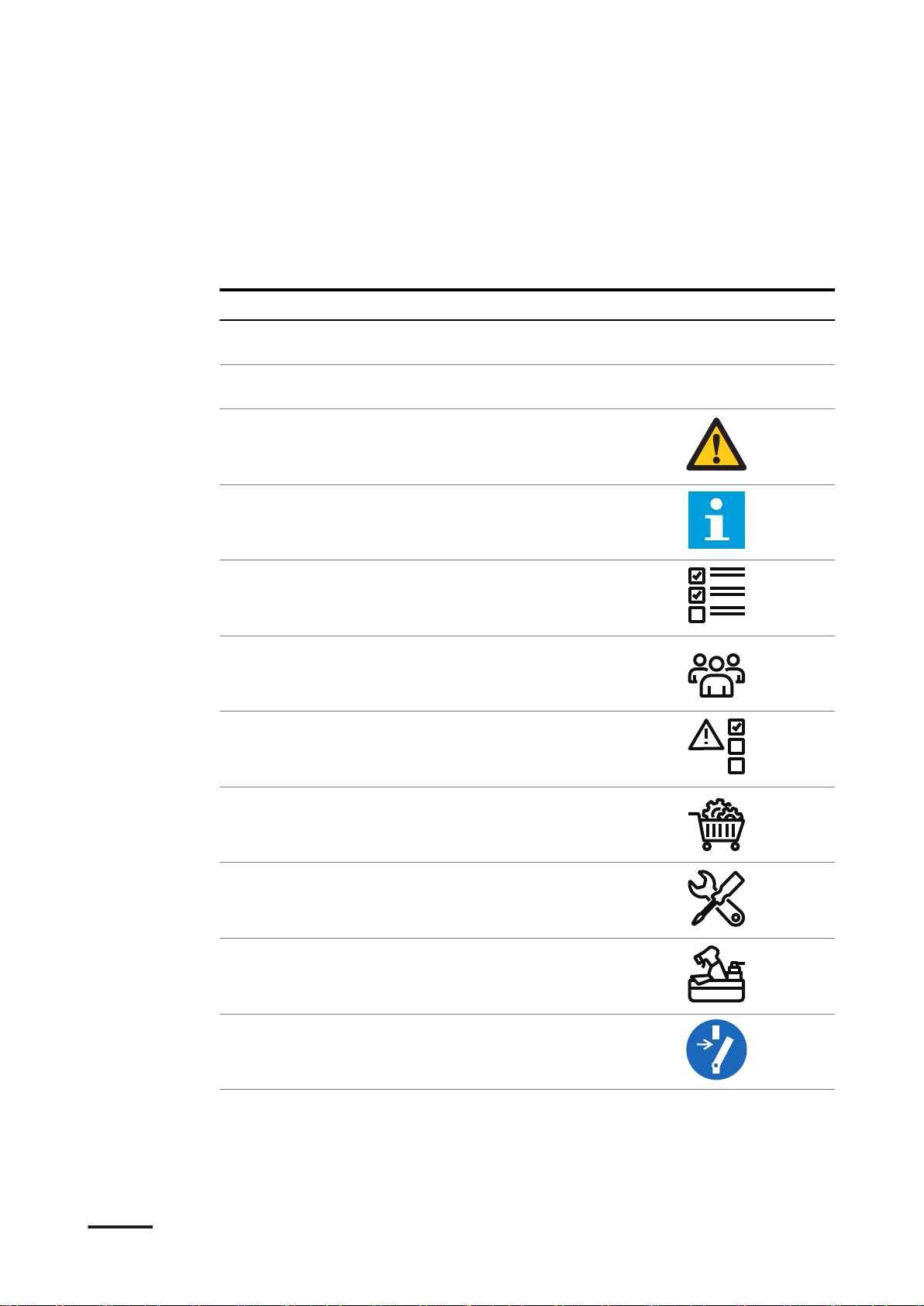
1.9 General symbols and signal words
Signal word Description Symbol
About this document
Danger If you do not obey the instruction, this
can cause injury or death.
Warning If you do not obey the instruction, this
can cause injury.
Caution If you do not obey the instruction, this
can cause damage to the EVSE or to
property.
Note A note gives more data, to make it easier
to do the steps, for example.
- Information about the condition of the
EVSE before you start the procedure.
- Requirements for personnel for a procedure.
- General safety instructions for a procedure.
Refer to section
1.10.
Refer to section
1.10.
- Information about spare parts that are
necessary for a procedure.
- Information about support equipment
that is necessary for a procedure.
- Information about supplies (consumables) that are necessary for a procedure.
- Make sure that the power supply to the
EVSE is disconnected.
BCM.V3Y00.0-EN | 002 7
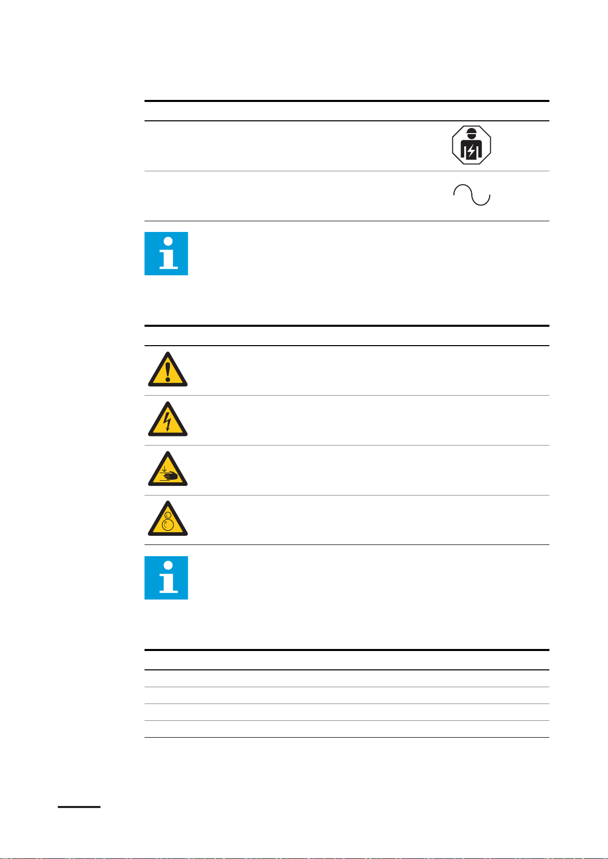
About this document
Signal word Description Symbol
- Electrotechnical expertise is required,
according to the local rules.
- Alternating current supply
Note: It is possible that not all symbols or signal words are present in
this document.
1.10 Special symbols for warnings and dangers
Symbol
Risk type
General risk
Hazardous voltage that gives risk of electrocution
Risk of pinching or crushing of body parts
Rotating parts that can cause a risk of entrapment
Note: It is possible that not all symbols are present in this document.
1.11 Related documents
Document name
Product data sheet All target groups
Installation manual Qualified installation engineer
User manual Owner
Declaration of conformity (CE) All target groups
You can find all related documents here: https://new.abb.com/ev-charging/terraac-wallbox.
8 BCM.V3Y00.0-EN | 002
Target group
1.12 Manufacturer and contact data
Manufacturer
ABB EV Infrastructure
George Hintzenweg 81
3068 AX, Rotterdam
The Netherlands
Contact data
ABB EV Infrastructure in your country can give you support on the EVSE. You can
find the contact data here: https://new.abb.com/ev-charging
1.13 Abbreviations
About this document
Abbreviation
AC Alternating current
CAN Controller area network
CPU Central processing unit
DC Direct current
EMC Electromagnetic compatibility
EV Electric vehicle
EVSE Electric vehicle supply equipment
MID Measuring Instruments Directive
NFC Near field communication
NoBo Notified body
OCPP Open charge point protocol
PE Protective earth
PPE Personal protective equipment
RFID Radio-frequency identification
Note: It is possible that not all abbreviations are present in this
document.
Definition
1.14 Terminology
Term
Network operating center
of the manufacturer
Cabinet Enclosure of the EVSE, including the components on
Contractor Third party that the owner or site operator hires to do
BCM.V3Y00.0-EN | 002 9
Definition
Facility of the manufacturer to do a remote check on
the correct operation of the EVSE
the inside
engineering, civil and electrical installation work
D
C
B
X
Z
Y
A
About this document
Term Definition
Grid provider Company that is responsible for the transport and dis-
Local rules All rules that apply to the EVSE during the entire lifecy-
Open charge point protocol
Owner Legal owner of the EVSE
Site operator Entity that is responsible for the day-to-day control of
User Owner of an EV, who uses the EVSE to charge the EV
tribution of electricity
cle of the EVSE. The local rules also include the national
laws and regulations.
Open standard for communication with charge stations
the EVSE. The site operator does not have to be the
owner.
Note: It is possible that not all terms are present in this document.
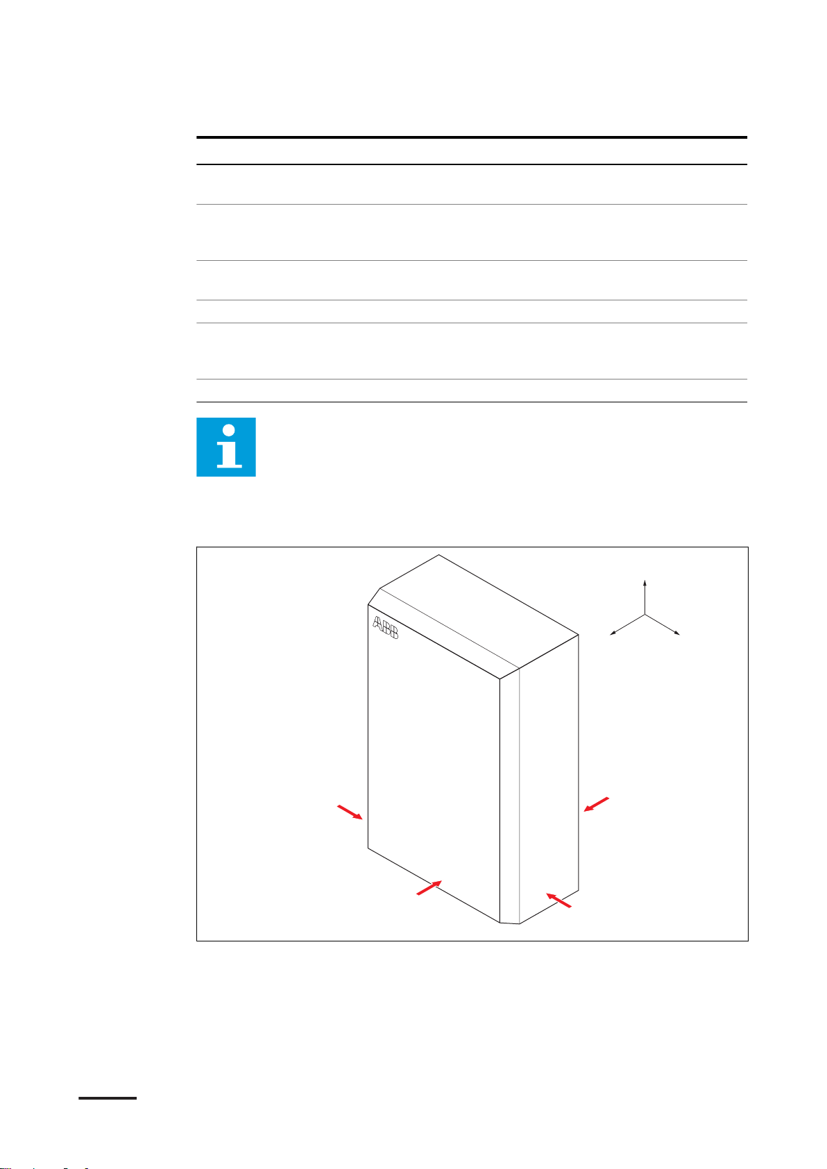
1.15 Orientation agreements
A Front side: face forward to the
EVSE during normal use
B Left side
C Right side
10 BCM.V3Y00.0-EN | 002
D Rear side
X X-direction (positive is to the right)
Y Y-direction (positive is rearward)
Z Z-direction (positive is upward)

2 Description
XXX XXXX
TAC Wxx-[L]-WWYY-zxxxx
Cert. No. xxxx/xxxxxxx
Checksum: xxxxxxxx
FW Version xxxxxx
Active energie Cl. B (1)
0.25-5(32)A
Weight: 3.0kg
3x220/380...3x240/415V-
Terra AC W22-T-RD-M-0
1000imp/kWh
2020-39
-30ºC-55ºC
50Hz
XXXXXXXXXX
George Hintzenweg 81,
3068 AX, Rotterdam,
The Netherlands
IP54
Made in China www.abb.com
A
B
C
D
E
F
H
G
J
I
K
L
M
O
N
2.1 Short description
The EVSE (Terra AC) is an AC charging station that you can use to supply electricity
to an EV. The Terra AC offers tailor-made, intelligent and network charging
solutions for your company or home. The EVSE can connect to the internet via GSM,
WiFi or LAN.
2.2 Intended use
The EVSE is intended for the AC charging of EVs. The EVSE is intended for indoor or
outdoor use.
The technical data of the EVSE must comply with the properties of the electrical
grid, the ambient conditions and the EV. Refer to chapter 7.
Only use the EVSE with accessories that the manufacturer provides or that obey the
local rules.
The EVSE AC input is intended for a hardwired installation that complies with the
applicable national regulations.
Description
Danger:
General risk
• If you use the EVSE in any other way than described in the related
documents, you can cause death, injury and damage to property.
• Use the EVSE only as intended.
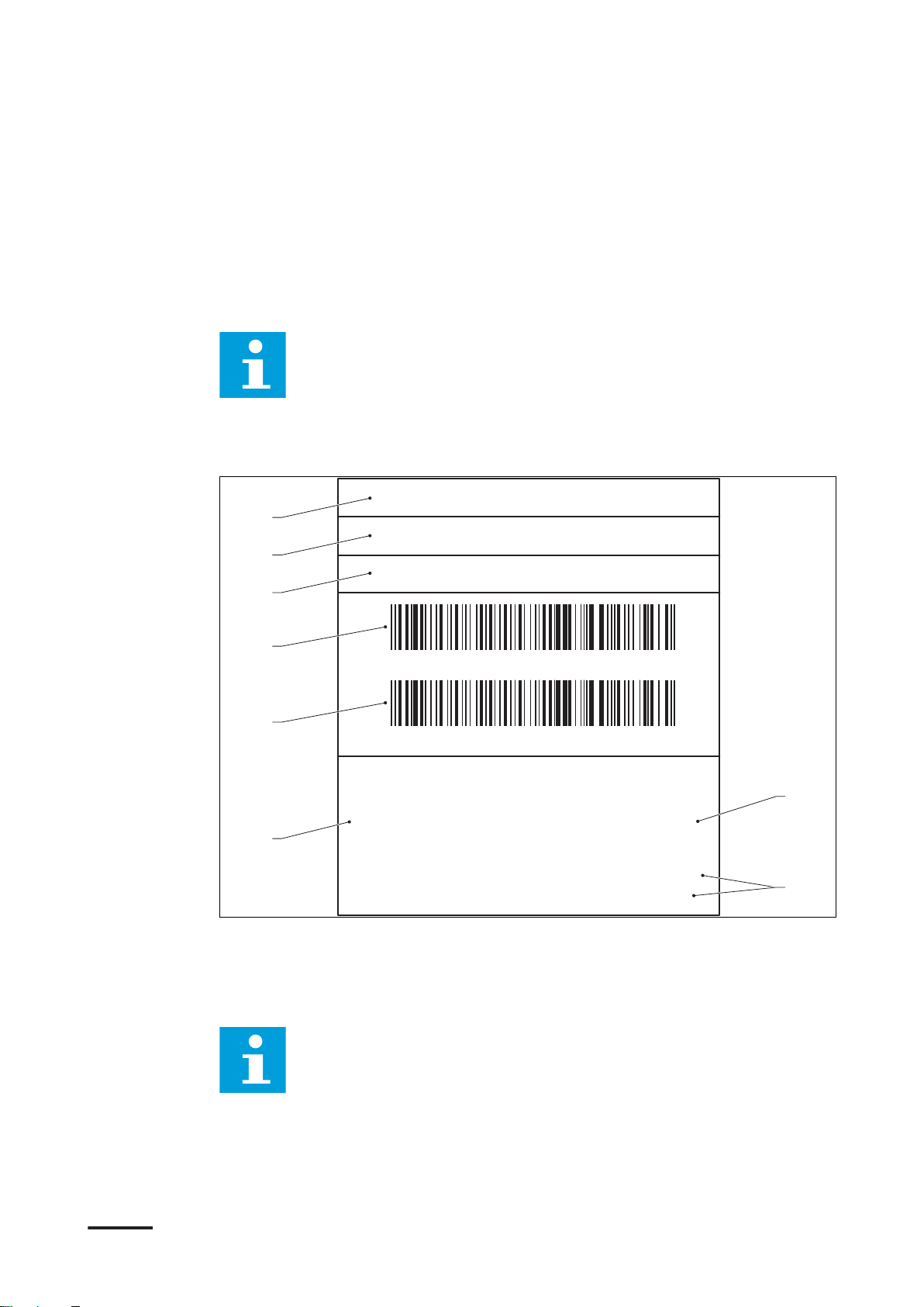
2.3 Product label (IEC portfolio)
BCM.V3Y00.0-EN | 002 11
SN: TACW7-[L]-WWYY-zxxxx
PN: XXXXXXXXXX
MODEL: Terra AC WX-P8-XX-XXX-X
TAC Wx-[L]-WWYY-zxxxx
XXXX XXXXXX
For use with electric vehicles
Pour utilisation avec des véhicules électriques
240V ~ / 60Hz 32A TYPE 3 -30ºC~50ºC
Ventilation Not Required Aucune ventilation requise
Raintight Étanche à la pluie Weight: 7.0kg
Dusttight Étanche à la poussière Poids: 7.0kg
A
B
C
D
E
F
G
H
Description
A Brand
B Barcode with the serial number
C Barcode with the part number of
the EVSE
D Product model number
E MID accuracy class
F EVSE rating
G Mass of the EVSE
H Address of the manufacturer
Note: The data in the illustration is only an example. Find the product
label on your EVSE to see the applicable data. Refer to section 2.5.2.
2.4 Product label (UL portfolio)
I CE mark
J MID mark and notified body
number
K MID certificate number
L MID software checksum
M MID FW version
N Ingress protection rating
O Reference to the manual
A Serial number
B Part number of the EVSE
C Product model number
D Barcode with the serial number of
the EVSE
Note: The data in the illustration is only an example. Find the product
label on your EVSE to see the applicable data. Refer to section 2.5.2.
E Barcode with the part number of
the EVSE
F Power rating of the EVSE
G Ambient temperature
H Mass of the EVSE
12 BCM.V3Y00.0-EN | 002
2.5 Overview
E
A B
CD
G
F
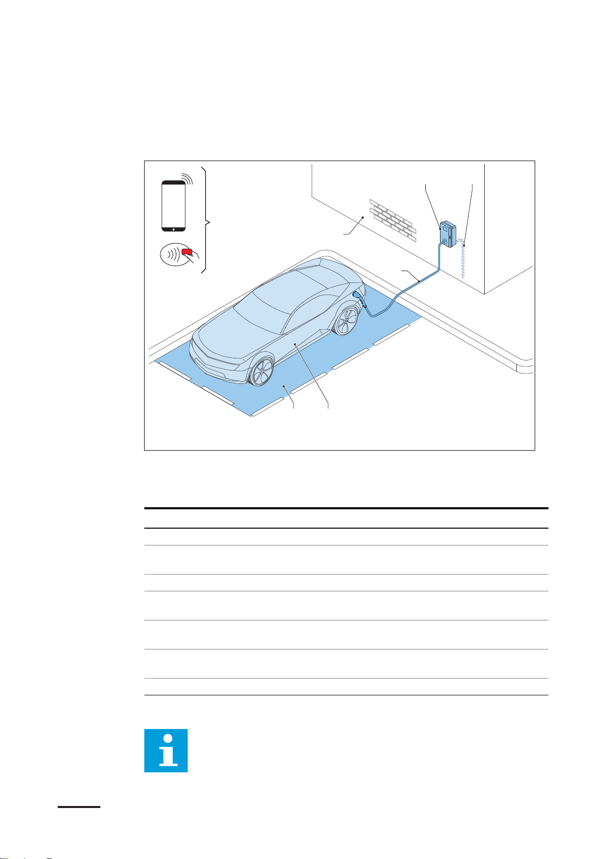
2.5.1 Overview of the system
Description
A EVSE
B AC grid input
C EV
D Parking space
Part Function
EVSE Refer to section 2.2.
Structure To install the EVSE on and to keep the
AC grid input To supply the electricity to the EVSE
EV charge cable To conduct the current from the EVSE to
EV The EV of which the batteries need to be
Parking space Location for the EV during the charge
RFID card or smartphone To authorize the user to use the EVSE
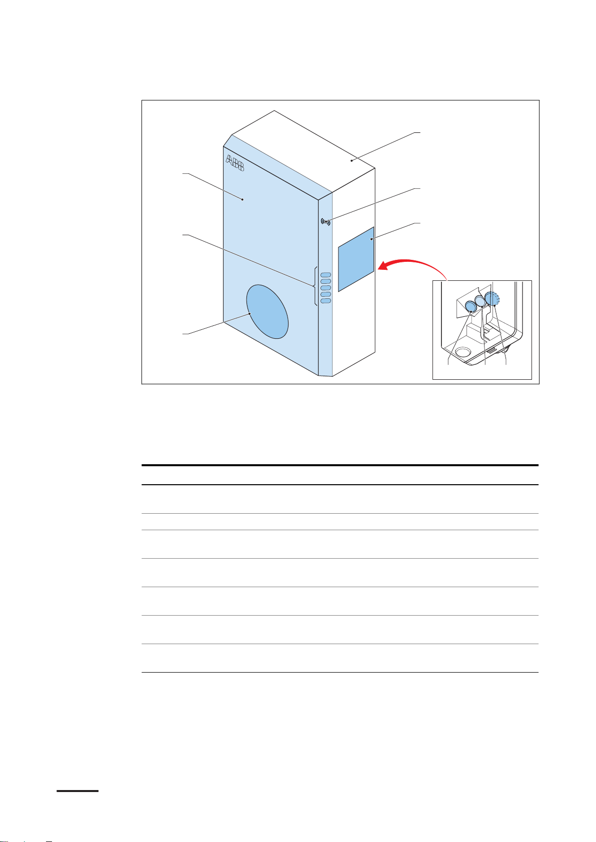
2.5.2 Overview of the EVSE, outside
The illustration shows the EVSE model without a display.
Note:
E RFID card or smartphone
F Structure to install the EVSE on
G EV charge cable
EVSE in position.
the EV
charged
session
BCM.V3Y00.0-EN | 002 13
A
F
E
H
I
G
B C D
Description
A Connection for the EV charge cable
B Openings for the smart meter
connections
C Opening for the Ethernet cable
D Opening for the AC input cable
E LED indicators
Part Function
Connection for the EV
charge cable
Openings Openings for the cables that go into the EVSE
LED indicators To show the status of the EVSE and the charge ses-
Cabinet cover To prevent a user to access the installation and main-
Enclosure To reduce the accessibillity of unqualified persons to
RFID reader To authorize the start or stop of a charging session
Product label To show the identification data of the EVSE. Refer to
To connect the EV charge cable
sion. Refer to section 2.7.1.
tenance parts of the EVSE
the inside of the EVSE
with an RFID card
section 2.3.
F Cabinet cover
G Enclosure
H RFID reader
I Product label
14 BCM.V3Y00.0-EN | 002

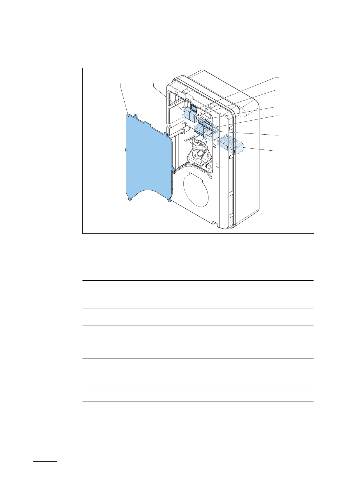
2.5.3 Overview of the EVSE, inside (CE model)
A B
C
E
D
F
G
Description
A Maintenance cover
B Primary Ethernet connection
C Socket for a Nano-M2M SIM card
D Smart meter connection
Part Function
Maintenance cover To prevent access to the electrical components of the
EVSE
Primary Ethernet connection
Socket for a Nano-M2M
SIM card
Smart meter connection To connect the cables for Modbus RTU - RS485
Terminal block for dry contacts input and output
Terminal block for the AC
input
Terminal block for the EV
charge cable
To connect the Ethernet cable
To connect the EVSE to the internet 4G
Not used
To connect the AC input cable from the grid
To connect the EV charge cable or the socket outlet
E Terminal block for dry contacts
input and output
F Terminal block for the AC input
G Terminal block for the EV charge
cable or the socket
BCM.V3Y00.0-EN | 002 15

A B C D
E
G
F
H
I
Description
2.5.4 Overview of the EVSE, inside (MID model)
A Maintenance cover
B Primary Ethernet connection
C Electrical pulse connector
D Socket for a Nano-M2M SIM card
E Terminal block for the AC input
Part Function
Maintenance cover To prevent access to the electrical components of the
EVSE
Primary Ethernet connection
Electrical pulse connector Use for manufacturer only. Do not change or connect
Socket for a Nano-M2M
SIM card
Terminal block for the AC
input
Secondary Ethernet connection
Smart meter connection To connect the cables for Modbus RTU - RS485
Terminal block for dry contacts input and output
Terminal block for the EV
charge cable
To connect the Ethernet cable
cables to this input yourself.
To connect the EVSE to the internet 4G
To connect the AC input cable from the grid
To use one Ethernet cable connection for multiple EVSEs. There is no communication between the EVSEs.
Not used
To connect the EV charge cable or the socket outlet
F Secondary Ethernet connection
G Smart meter connection
H Terminal block for dry contacts
input and output
I Terminal block for the EV charge
cable or the socket
16 BCM.V3Y00.0-EN | 002
2.5.5 Overview of the EVSE, inside (UL model)
A B
C
D
F
E
G
H
Description
A Maintenance cover
B Primary Ethernet connection
C Socket for a Nano-M2M SIM card
D Secondary Ethernet connection
Part Function
Maintenance cover To prevent access to the electrical components of the
EVSE
Primary Ethernet connection
Socket for a Nano-M2M
SIM card
Secondary Ethernet connection
Smart meter connection To connect the cables for Modbus RTU - RS485
Terminal block for dry contacts input and output
Terminal block for the AC
input
Terminal block for the EV
charge cable or the socket
To connect the Ethernet cable
To connect the EVSE to the internet 4G
To use one Ethernet cable connection for multiple EVSEs. There is no communication between the EVSEs.
Not used
To connect the AC input cable from the grid
To connect the EV charge cable or the socket outlet
E Smart meter connection
F Terminal block for dry contacts
input and output
G Terminal block for the AC input
H Terminal block for the EV charge
cable or the socket
BCM.V3Y00.0-EN | 002 17

A B C
D
F
E
G
H
Description
2.5.6 Overview of the EVSE, inside (UL model with display)
A Maintenance cover
B Primary Ethernet connection
C Socket for a Nano-M2M SIM card
D Terminal block for the AC input
Part Function
Maintenance cover To prevent access to the electrical components of the
EVSE
Primary Ethernet connection
Socket for a Nano-M2M
SIM card
Terminal block for the AC
input
Secondary Ethernet connection
Smart meter connection To connect the cables for Modbus RTU - RS485
Terminal block for dry contacts input and output
Terminal block for the EV
charge cable or the socket
To connect the Ethernet cable
To connect the EVSE to the internet 4G
To connect the AC input cable from the grid
To use one Ethernet cable connection for multiple EVSEs. There is no communication between the EVSEs.
Not used
To connect the EV charge cable or the socket outlet
E Secondary Ethernet connection
F Smart meter connection
G Terminal block for dry contacts
input and output
H Terminal block for the EV charge
cable or the socket
18 BCM.V3Y00.0-EN | 002

2.6 Options
A
A
2.6.1 Display
A Display
For more data about the display, refer to section 2.9.
Description
2.6.2 EV charge cable, Type 2
2.6.3 Socket, Type 2
BCM.V3Y00.0-EN | 002 19
A Socket

Description
The socket for an EV charge cable Type 2 is available with or without a shutter.
2.6.4 EV charge cable, Type 1 (UL portfolio)
2.6.5 Load management
Load management makes sure that the available electrical capacity of the building
or home is not exceeded. A number of devices share a grid connection, that has a
maximum capacity. The total power demand of the devices that use the grid
connection must not exceed the grid capacity.
The load management feature prevents that the system exceeds the grid capacity
and prevents damage of the fuses. At times when the current demand is high, the
EVSE decreases the output of current. The current will increase again when there is
availability on the grid.
Also, the load management feature makes sure that the available load is optimally
shared.
20 BCM.V3Y00.0-EN | 002

2.7 Control elements
A
B
C
D
E
2.7.1 LED indicators
Description
A Error LED
B Charging LED
C Cable and EV detection, and EV
authorization LED
Table 1: Error LED
Status of the LED
On Error
Off No error
Table 2: Charging LED
Status of the LED
On EV is fully charged or has stopped
Off Not charging
Flashing Charging
D Internet connection LED
E EVSE on/off LED
Status of the EVSE
Status of the EVSE
charging
BCM.V3Y00.0-EN | 002 21

Description
Table 3: Cable and EV detection, and EV authorization LED
Status of the LED Status of the EVSE
On An EV is connected. The connection is
authorized.
Off No EV connected
Flashing A EV is connected, waiting for authoriza-
tion
Table 4: Internet connection LED
Status of the LED Status of the EVSE
On Connected to the internet
Off Not connected to the internet
Flashing In progress to establish internet con-
nection
Table 5: EVSE on/off LED
Status of the LED
On The EVSE is on
Off The EVSE is off
Flashing The EVSE is in setup
Status of the EVSE
2.8 Description of the ChargerSync app for the EVSE
The
ChargerSync
app is available on the
Apple Store
and on the
Google Play Store
.
22 BCM.V3Y00.0-EN | 002

2.8.1 General description of the lay-out of the ChargerSync app
9:41
My Chargers Bluetooth Connecting
TACW224179G4567
Unavailable
Functions Statistics
Schedule Load Balance Energy Plan
Carger Link Card Firmware update
Home Start charge Me
B
A
C
Description
A Menu title
C Navigation bars
B Main screen area
Screen part Description
Menu title This area shows the current menu.
Main screen area This area shows information about the status of the
EVSE, the charge sessions and the available menus.
Navigation bars To navigate through the menus of the app and to use
the functions. For a description of the buttons, refer to
section 2.8.2.
2.8.2 General description of the buttons and colors
Button
Name / color Description
Home To go to the main menu
Start button To start the charge session
Account button To go to the account menu, that has the
personal preferences and settings
BCM.V3Y00.0-EN | 002 23

$
Description
Button Name / color Description
Schedule To go to the schedule menu
Energy plan To go to the energy plan menu
Load balance To go to the load balance menu
Firmware ugrade To go to the firmware upgrade menu
Charger link To go to the charger link connectivity
menu
Previous To go to a previous page
Add or delete card To add or delete RFID cards
Next To go to a next page
2.8.3 Overview of the menus
Menu
Login menu Shows the fields to log in.
Account menu Shows the personal preferences and settings
Setup menu Shows the screens to set up the EVSE
Main menu Shows:
Description
• Navigation buttons
• Buttons to manage the charge session
• Information about the current charge session
Schedule menu To create a schedule for a charge session
Energy plan menu To select an energy plan for the charge session
Load balance menu To adjust the settings of load management
Firmware upgrade menu Shows available firmware versions and the possibillity to
start a product firmware update1.
24 BCM.V3Y00.0-EN | 002

Menu Description
Total :
325.634,622 KWh 30.07.2020 10:30
SN : TACW2240120G4567
v
00.55.19
A B
C D E
Description
Charger link connectivity
To connect your EVSE to a network
menu
Add or delete card menu To add or delete RFID cards
2.8.4 Errors
If the EVSE detects a problem, the error LED comes on. The
the error description. For the possible causes and the possible solutions, refer to
section 6.2.
ChargerSync
2.9 Description of the display screens (option)
2.9.1 Boot screen
app shows
2.9.2 Standby/Idle screen
During the start up of the EVSE, the display shows the Boot screen.
A Total delivered energy
B Date
D Serial number
E Firmware version (MID certified)
C Guide
The display shows the Standby/Idle screen when the EVSE is in idle status. Then,
the EVSE is available for a charge session.
1
It can be necessary to update in multiple steps, until the app does not detect newer firmware.
The app updates one firmware version at a time.
BCM.V3Y00.0-EN | 002 25

30.07.2020 10:30
Total : 325.637,622 kWh
SN : TACW2240120G4567 v 00.55.19
30.07.2020 10:30
Total : 325.637,622 kWh
SN : TACW2240120G4567
v 00.55.19
30.07.2020 10:30
Total : 325.637,622 kWh
SN : TACW2240120G4567 v 00.55.19
Description
2.9.3 Authorization screen
The display shows different Authorization screens, dependent on the situation.
The display shows this Authorization screen when the EV charge cable is connected
to the EV but the charge session is not authorized:
The display shows this Authorization screen when the charge session is authorized
but the EV charge cable is not connected to the EV:
2.9.4 Preparing to charge screen
2.9.5 Charging screen
The display shows the Charging screen during the charge session.
The display shows this Charging screen for a single phase EVSE:
26 BCM.V3Y00.0-EN | 002

30.07.2020 10:30
231,5V
31,86A
20,180kWh
02:41
7,3
kW
SN :
TACW2240120G4567
Total : 325.637,622 kWh
v 00.55.19
A B C
30.07.2020 09:28
231,5V
31,86A
60,541kWh
02:41
21,9
kW
SN :
TACW2240120G4567
Total : 325.637,622 kWh
v 00.55.19
A
30.07.2020 09:35
30.07.2020 06:54 - 30.07.2020 09:35
60,541kWh 02:41
SN :
TACW2240120G4567 v 00.55.19
Total : 325.637,622 kWh
A B
Description
A Real-time voltage and current
B Real-time active power
The display shows this Charging screen for a 3 phase EVSE:
A Real-time voltage and current per
phase
2.9.6 Charging completed screen
C Energy delivered and duration of
the charge session
2.9.7 Fault detected display messages
BCM.V3Y00.0-EN | 002 27
A Start and end time
B Energy delivered and duration of
the charge session
The display shows different fault detected images, dependent on the type of fault.

0x0010
30.07.2020 09:35
Total : 325.637,622 kWh
SN : TACW2240120G4567 v 00.55.19
A
0x0010
30.07.2020 09:35
Total : 325.637,622 kWh
SN : TACW2240120G4567 v 00.55.19
A
30.07.2020 10:30
Total : 325.637,622 kWh
SN : TACW2240120G4567 v 00.55.19
Description
Disconnect the charge cable and connect it again:
A Error code
Contact your service provider:
A Error code
The EV is not ready for the charge session:
28 BCM.V3Y00.0-EN | 002

3 Safety
3.1 Liability
The manufacturer is not liable to the purchaser of the EVSE or to third parties for
damages, losses, costs or expenses incurred by the purchaser or third parties if any
target group mentioned in the related documents does not obey the rules below:
• Obey the instructions in the related documents. Refer to section 1.11.
• Do not misuse or abuse the EVSE.
• Only make changes to the EVSE, if the manufacturer approves in writing of the
changes.
This EVSE is designed to be connected to and to communicate information and
data via a network interface. It is the sole responsibility of the owner to provide and
continuously ensure a secure connection between the EVSE and the network of the
owner or any other network.
The owner shall establish and maintain any appropriate measures (such as - but not
limited to - the installation of firewalls, application of authentication measures,
encryption of data and installation of anti-virus programs) to protect the EVSE, the
network, its system and the interface against any kind of security breaches,
unauthorized access, interference, intrusion, leakage and/or theft of data or
information.
The manufacturer is not liable for damages and/or losses related to such security
breaches, any unauthorized access, interference, intrusion, leakage and/or theft of
data or information.
Safety
3.2 Responsibilities for the owner
The owner is the person who runs the EVSE for commercial or business purposes
for itself or leaves it to a third party for use. During operation the owner bears legal
responsibility for the protection of the user, other employees or third parties. The
owner has the responsibilities that follow:
• To know and implement the local rules
• To identify the hazards (in terms of a risk assessment), resulting from the
working conditions on the site
• To operate the EVSE with the protective devices installed
• To make sure that all protective devices are installed after installation or
maintenance work
• To make an emergency plan that instructs people what to do in case of an
emergency
• To make sure that all employees and third parties are qualified according to the
applicable local rules to do the work
• To make sure that there is sufficient space around the EVSE to safely do
maintenance and installation work
• To identify a site operator who is responsible for the safe operation of the EVSE
and for the coordination of all work, if the owner does not do these tasks
BCM.V3Y00.0-EN | 002 29

Safety
3.3 Personal protective equipment
Symbol Description
Protective clothing
Safety gloves
Safety shoes
Safety glasses
3.4 FCC compliance statement
Caution: Changes or modifications not expressly approved by the party
responsible for compliance could void the user's authority to operate the
equipment.
Note: This equipment has been tested and found to comply with the
limits for a Class B digital device, pursuant to part 15 of the FCC Rules.
These limits are designed to provide reasonable protection against
harmful interference in a residential installation. This equipment
generates, uses and can radiate radio frequency energy and, if not
installed and used in accordance with the instructions, may cause
harmful interference to radio communications. However, there is no
guarantee that interference will not occur in a particular installation. If
this equipment does cause harmful interference to radio or television
reception, which can be determined by turning the equipment off and on,
the user is encouraged to try to correct the interference by one or more
of the following measures:
• Reorient or relocate the receiving antenna.
• Increase the separation between the equipment and receiver.
• Connect the equipment into an outlet on a circuit different from that
to which the receiver is connected.
• Consult the dealer or an experienced radio/TV technician for help.
3.5 Industry Canada compliance statement
This device contains licence-exempt transmitter(s)/receiver(s) that comply with
Innovation, Science and Economic Development Canada’s licence-exempt RSS(s).
Operation is subject to the following two conditions:
30 BCM.V3Y00.0-EN | 002

• This device may not cause interference.
• This device must accept any interference, including interference that may cause
undesired operation of the device.
RF exposure statement
This equipment complies with IC radiation exposure limits set forth for an
uncontrolled environment. This equipment should be installed and operated with
minimum distance 20cm between the radiator and your body.
3.6 General safety instructions
• This document, the related documents and the warnings included do not
replace your responsibility to use your common sense when you do work on the
EVSE.
• Only do the procedures that the related documents show and that you are
qualified for.
• Obey the local rules and the instructions in this manual. If the local rules
contradict the instructions in this manual, the local rules will apply.
If and to the extent permitted by law, in case of inconsistency or contradiction,
between any requirements or procedure contained in this document and any
such local rules, obey the stricter between the requirements and procedures
specified in this document and the local rules.
Safety
3.7 Safety instructions for use
• In these situations, do not use the EVSE and immediately contact the
manufacturer:
• An enclosure has damage.
• An EV charge cable or connector has damage.
• Lightning struck the EVSE.
• There was an accident or a fire at or near the EVSE.
• Water has entered the EVSE.
3.8 Safety instructions during cleaning or maintenance
Preliminary requirements
•
• Keep unauthorized personnel at a safe distance during cleaning or maintenance.
• If for cleaning or maintenance it is necessary to remove safety devices,
immediately install the safety devices after the work.
• Put on the correct personal protective equipment. Refer to section 3.3.
BCM.V3Y00.0-EN | 002 31

Safety
3.9 Signs on the EVSE
Symbol Risk type
General risk
Hazardous voltage that gives risk of electrocution
Risk of pinching or crushing of body parts
Rotating parts cat can cause a risk of entrapment
PE
Sign that means that you must read the manual before
you install the EVSE
Waste from electrical and electronic equipment
Note: It is possible that not all symbols are present on the EVSE.
3.10 Discard the EVSE or parts of the EVSE
Incorrect waste handling can have a negative effect on the environment and human
health due to potential hazardous substances. With the correct disposal of this
product, you contribute to reuse and recycling of materials and protection of the
environment.
• Obey the local rules to discard parts, packaging material or the EVSE.
• Discard electrical and electronic equipment separately in compliance with the
WEEE - 2012/19/EU Directive on waste of electrical and electronic equipment.
• As the symbol of the crossed out wheeled-bin on your EVSE indicates, do not
mix or dispose the EVSE with your household waste, at the end of use. Instead,
hand the EVSE over to your local community waste collection point for recycling.
• For more information, contact the Government Waste-Disposal department in
your country.
32 BCM.V3Y00.0-EN | 002

3.11 Special safety instructions (UL portfolio)
3.11.1 Important safety instructions (UL portfolio)
Warning: Obey the basic precautions for electric products, including the
instructions in this section.
Caution: To reduce the risk of fire, connect this EVSE only to a circuit
provided with 40 A maximum branch circuit overcurrent protection in
accordance with the National Electrical Code, ANSI/NFPA 70.
• Read all the instructions befor you use this EVSE.
• Make sure that adults supervise this EVSE is when it is used around children.
• Do not put fingers into the EV connector.
• Do not use this product if the flexible power cord or EV charge cable is frayed,
has broken insulation, or any other signs of damage.
• Do not use this EVSE if the enclosure or the EV connector is broken, cracked,
open, or shows any other indication of damage.
• Install an insulated grounding conductor that is identical in size, insulation
material, and thickness to the grounded and ungrounded branch-circuit supply
conductors, except that it is green with or without one or more yellow stripes,
as part of the branch circuit that supplies the EVSE.
• Connect the grounding connector of the previous bullet point to earth at the
EVSE or, when supplied by a separately derived system, at the supply
transformer.
Safety
Closing requirements
SAVE THESE INSTRUCTIONS
1.
BCM.V3Y00.0-EN | 002 33

Operation
4 Operation
4.1 Prepare before use
1. Appoint a site operator and an installation engineer, if these are other persons
than you.
2. Make sure that the equipment is installed and commissioned according to the
instructions in the installation manual.
3. Make an emergency plan that instructs people what to do in case of an
emergency.
4. Make sure that the space around the equipment cannot get blocked. Think of
snow or other objects. Refer to the space requirements. Refer to section 7.6.3.
5. Make sure that maintenance is done on the equipment. Refer to section 5.
4.2 Energize the EVSE
1. Close the breaker that supplies the power to the EVSE.
Warning:
Hazardous voltage
• Be careful when you work with electricity.
• The power supply comes on.
• A series of self-checks start, to make sure that the EVSE works correctly and
safely.
• If the EVSE detects a problem, the error LED comes on. The
shows the description of the error.
4.3 Connect the EVSE with the ChargerSync app
Preliminary requirements
• Mobile device with the
Procedure
1. Find your pin code in the package with the RFID card.
• The pin code has 8 characters.
• The letters are case-sensitive.
ChargerSync
app
ChargerSync
app
2. Download the
3. Start the
4. Do the instructions that the
34 BCM.V3Y00.0-EN | 002
ChargerSync
ChargerSync
App from the
app.
ChargerSync
Google Play Store
app shows.
or
App Store
.

4.4 Start a charge session
4.4.1 EVSE with an EV charge cable
Caution: During the charge session, do not disconnect the EV charge
cable from the connection on the EV. There is a risk of damage of the
connector of the EV.
Note: The LEDs show the status of the charge session.
1. Take the EV charge cable from the enclosure.
2. Use your RFID card or
The authorization of the connection to the EV starts.
3. Connect the EV charge cable to connector of the EV.
The EVSE charges the EV.
ChargerSync
Operation
app to authorize the use of the EVSE.
4.4.2 EVSE with a socket
Caution: During the charge session, do not disconnect the EV charge
cable. There is a risk of damage of the socket of the EVSE or the
connector of the EV.
Note: The LEDs show the status of the charge session.
1. Connect your EV charge cable to the connection on your EV.
2. Use your RFID card or
The authorization of the connection to the EV starts.
3. Connect the EV charge cable to the socket of the EVSE.
The EVSE charges the EV.
ChargerSync
app to authorize for use of the EVSE.
4.5 Wake up the EV when it is unavailable
4.5.1 Wake up the EV (EVSE without display)
Preliminary requirements
1. The
Procedure
1. Disconnect the EV charge cable from the EV.
2. Connect the EV charge cable to the EV again.
BCM.V3Y00.0-EN | 002 35
ChargerSync
app shows 'waiting for EV'.

Operation
4.5.2 Wake up the EV (EVSE with display)
Preliminary requirements
1. The display shows that the EV is not ready for the charge session.
Procedure
1. Disconnect the EV charge cable from the EV.
2. Connect the EV charge cable to the EV again.
4.6 Stop a charge session
4.6.1 EVSE with an EV charge cable
Caution: During the charge session, do not disconnect the EV charge
cable from the connector on the EV. There is a risk of damage of the
connector of the EV.
Note: If you disconnect the EV charge cable during the charge session,
the EVSE automatically disconnects the power supply. This stops all
charging operations.
1. Select one of the two ways to end the charge session.
• Wait until the charge session is completed.
• The
• The charging LED is on.
• If your EVSE has a display, the display shows that the charge session is
When the charge session is completed, the EVSE disconnects the power
supply automatically.
• Authorize the ending of the use of the EVSE with your RFID card or the
ChargerSync
2. Disconnect the EV charge cable from the EV.
3. Wrap the EV charge cable around the enclosure. Refer to section 4.7.
ChargerSync
completed.
app. The authorization of the disconnection to the EV starts.
4.6.2 EVSE with a socket
Caution: During the charge session, do not disconnect the EV charge
cable. There is a risk of damage of the socket of the EVSE or the
connector of the EV.
app shows that the charge session is completed.
Note: If you disconnect the EV charge cable during the charge session,
the EVSE automatically disconnects the power supply. This stops all
charging operations.
36 BCM.V3Y00.0-EN | 002

1. Select one of the two ways to end the charge session.
• Wait until the charge session is completed.
Operation
• The
• The charging LED is on.
• If your EVSE has a display, the display shows that the charge session is
When the charge session is completed, the EVSE disconnects the power
supply automatically.
• Authorize the ending of the use of the EVSE with your RFID card or the
ChargerSync
2. Disconnect the EV charge cable from the socket of the EVSE.
3. Disconnect the EV charge cable from the connector on the EV.
ChargerSync
completed.
app. The authorization of the disconnection to the EV starts.
app shows that the charge session is completed
4.7 Wrap the EV charge cable around the enclosure
1. Wrap the EV charge cable around the
enclosure.
BCM.V3Y00.0-EN | 002 37

Maintenance and cleaning
5 Maintenance and cleaning
5.1 Maintenance schedule
Task Frequency Procedure
Clean the cabinet cover
and the enclosure of the
EVSE.
Do a visual check for damage on the cabinet.
Do a visual check for damage on the EV charge cables or outlet and the connectors.
5.2 Clean the cabinet
Preliminary requirements
• Cleaning agent. Refer to section 7.9.
• Non-abrasive tool. Refer to section 7.9.
Danger:
Hazardous voltage
• Do not apply high-pressure water jets. Water can leak into the
cabinet.
4 months Refer to section 7.9.
Before each use Refer to section 5.3.
Before each use Refer to section 5.3.
Note: When the EVSE is put in a corrosion sensitive environment,
superficial rust is possible on welding points. This rust is only visual.
There is no risk for the integrity of the cabinet. The procedure below
removes the rust.
Procedure
1. Rinse with low-pressure tap water to remove rough dirt.
2. Apply a a solution of cleaning agent to the cabinet and let it soak.
3. Manually remove dirt. Use the non-abrasive tool.
Caution: Do not use abrasive tools.
4. Rinse with low-pressure tap water.
5. If necessary, apply wax on the front for extra protection and gloss.
6. If there was rust and you want it not to appear again, apply a rust-preventive
primer. Ask the manufacturer for specifications and instructions.
38 BCM.V3Y00.0-EN | 002

5.3 Do a check on the cabinet
1. Do a check for damage on these parts:
Part Damage
Charge cables, outlets and connectors Cracks or ruptures
Display Cracks
Coating of the cabinet Cracks or ruptures
2. If you see damage, contact the manufacturer. Refer to section 1.12.
Maintenance and cleaning
Internal wires of the cable are visible
BCM.V3Y00.0-EN | 002 39

Troubleshooting
6 Troubleshooting
6.1 Troubleshooting procedure
1. Try to find a solution for the problem with the aid of the information in this
document.
2. If you cannot find a solution for the problem, contact your local representative
of the manufacturer. Refer to section 1.12.
6.2 Troubleshooting table (IEC portfolio)
Problem (error
code)
Residual current
detected (0x0002)
PE missing or swap
neutral and phase
(0x0004)
Over voltage
(0x0008)
Under voltage
(0x0010)
Over current
(0x0020)
Severe over current
(0x0040)
Possible cause Possible solution
There is residual current
(30mA AC or 6mA DC) in
the charge circuit. Current
leaks into the ground.
The EVSE is not earthed
correctly or neutral and
phase wires are swapped.
The maximum voltage on
the power input is too
high.
The voltage on the power
input is not sufficient.
There is an overload on the
EV side.
There is an overload on the
EV side.
1. De-energize the EVSE. Refer
to section 6.4.
2. Contact your local representative of the manufacturer or a
qualified electrical contractor.
Refer to section 1.12.
Contact your local representative
of the manufacturer or a qualified
electrical contractor. Refer to section 1.12.
Contact your local representative
of the manufacturer or a qualified
electrical contractor. Refer to section 1.12.
Contact your local representative
of the manufacturer or a qualified
electrical contractor. Refer to section 1.12.
Contact your local representative
of the manufacturer or a qualified
electrical contractor. Refer to section 1.12.
Contact your local representative
of the manufacturer or a qualified
electrical contractor. Refer to section 1.12.
40 BCM.V3Y00.0-EN | 002

Troubleshooting
Problem (error
code)
Over temperature
(0x0080)
Power relay fault
(0x0400)
Possible cause Possible solution
The internal temperature
is too high.
The relay contact is detected in wrong state or has
damage.
1. Do a check of the operation
temperature on the product
label. If the ambient temperature is too high, the EVSE will
decrease the output current
automatically.
2. If it is necessary, install the
EVSE in an environment with a
lower ambient temperature.
3. Do the procedure that is described for the problem 'the
AC input voltage is too high'.
4. If you can not solve the problem, do not use the EVSE.
Contact your local company
representative or a qualified
electrical contractor. Refer to
section 1.12.
1. Examine the relay contact.
2. If necessary, contact your local representative of the manufacturer or a qualified electrical contractor. Refer to section 1.12.
Internal communication failure
(0x0800)
E-Lock failure
(0x1000)
Missing phase
(0x2000)
Modbus communication lost
(0x4000)
The internal boards of the
EVSE fail to communicate
with each other.
Error to lock / unlock the
charge connector.
B and C phase are missing
or one of these phases is
missing.
The Modus communication is lost.
1. Connect the EVSE to the internet.
2. Do a check of the WiFi signal
at the site
3. Do a check of the Nano-SIM
card connection and the 4G
signal strength at the site.
1. Examine the connection of
the EV charge cable.
2. If necessary, contact your local representative of the manufacturer or a qualified electrical contractor. Refer to section 1.12.
Contact your local representative
of the manufacturer or a qualified
electrical contractor. Refer to section 1.12.
Contact your local representative
of the manufacturer or a qualified
electrical contractor. Refer to section 1.12.
BCM.V3Y00.0-EN | 002 41

Troubleshooting
Problem (error
code)
The display shows
that the EV is not
ready for the
charge session or
the
ChargerSync
app shows 'waiting
for EV'
The EV is not charg-edThere is a problem with
Possible cause Possible solution
The EV is in unavailable Wake up the EV. Refer to section
the EVSE
The EV charge cable is defective.
4.5.
1. Make sure that the power
supply to the EVSE is on.
2. Examine the EVSE to find if is
working correctly.
3. Examine the
and the charge LED to make
sure that the charging session
is authorized.
4. Start the charging session.
1. Examine the EV charge cable.
2. If the EV charge cable is defective, contact your local representative of the manufacturer or a qualified electrical
contractor. Refer to section
1.12.
ChargerSync
app
The EV connection
or authorization
process fails
The EV charge cable is defective.
1. Examine the EV charge cable.
2. If the EV charge cable is defective, contact your local representative of the manufacturer or a qualified electrical
contractor. Refer to section
1.12.
42 BCM.V3Y00.0-EN | 002

Troubleshooting
Problem (error
code)
Possible cause Possible solution
The EV charge cable is not
connected correctly.
There is a problem with
the
ChargerSync
the RFID card.
app or
1. Examine the connection of
the EV charge cable.
2. If necessary, contact your local representative of the manufacturer or a qualified electrical contractor. Refer to section 1.12.
1. Make sure that you have registered in the
app.
2. Make sure that you use a RFID
card that the manufacturer
provided.
3. Make sure that the RFID card
is added on the
app.
4. Start the
5. Start the authorization process.
ChargerSync
ChargerSync
ChargerSync
app.
6.3 Troubleshooting table (UL portfolio)
Problem (error
code)
Residual current
detected (0x0002)
PE missing or swap
neutral and phase
(0x0004)
Over voltage
(0x0008)
Under voltage
(0x0010)
Over current
(0x0020)
Possible cause Possible solution
There is residual current
(20mA AC) in the charge
circuit. Current leaks into
the ground.
The EVSE is not earthed
correctly or neutral and
phase wires are swapped.
The maximum voltage on
the power input is too
high.
The voltage on the power
input is not sufficient.
There is an overload on the
EV side.
1. De-energize the EVSE. Refer
2. Contact your local representa-
Contact your local representative
of the manufacturer or a qualified
electrical contractor. Refer to section 1.12.
Contact your local representative
of the manufacturer or a qualified
electrical contractor. Refer to section 1.12.
Contact your local representative
of the manufacturer or a qualified
electrical contractor. Refer to section 1.12.
Contact your local representative
of the manufacturer or a qualified
electrical contractor. Refer to section 1.12.
to section 6.4.
tive of the manufacturer or a
qualified electrical contractor.
Refer to section 1.12.
BCM.V3Y00.0-EN | 002 43

Troubleshooting
Problem (error
code)
Severe over current
(0x0040)
Over temperature
(0x0080)
Possible cause Possible solution
There is an overload on the
EV side.
The internal temperature
is too high.
Contact your local representative
of the manufacturer or a qualified
electrical contractor. Refer to section 1.12.
1. Do a check of the operation
temperature on the product
label. If the ambient temperature is too high, the EVSE will
decrease the output current
automatically.
2. If it is necessary, install the
EVSE in an environment with a
lower ambient temperature.
3. Do the procedure that is described for the problem 'the
AC input voltage is too high'.
4. If you can not solve the problem, do not use the EVSE.
Contact your local company
representative or a qualified
electrical contractor. Refer to
section 1.12.
Power relay fault
(0x0400)
Internal communication failure
(0x0800)
E-Lock failure
(0x1000)
Missing phase
(0x2000)
The relay contact is detected in wrong state or has
damage.
The internal boards of the
EVSE fail to communicate
with each other.
Error to lock / unlock the
charge connector.
B and C phase are missing
or one of these phases is
missing.
1. Examine the relay contact.
2. If necessary, contact your local representative of the manufacturer or a qualified electrical contractor. Refer to section 1.12.
1. Connect the EVSE to the internet.
2. Do a check of the WiFi signal
at the site
3. Do a check of the Nano-SIM
card connection and the 4G
signal strength at the site.
1. Examine the connection of
the EV charge cable.
2. If necessary, contact your local representative of the manufacturer or a qualified electrical contractor. Refer to section 1.12.
Contact your local representative
of the manufacturer or a qualified
electrical contractor. Refer to section 1.12.
44 BCM.V3Y00.0-EN | 002

Troubleshooting
Problem (error
code)
Modbus communication lost
(0x4000)
The display shows
that the EV is not
ready for the
charge session or
the
ChargerSync
app shows 'waiting
for EV'
The EV is not charg-edThere is a problem with
Possible cause Possible solution
The Modus communication is lost.
The EV is unavailable Wake up the EV. Refer to section
the EVSE
Contact your local representative
of the manufacturer or a qualified
electrical contractor. Refer to section 1.12.
4.5.
1. Make sure that the power
supply to the EVSE is on.
2. Examine the EVSE to find if is
working correctly.
3. Examine the
and the charge LED to make
sure that the charging session
is authorized.
4. Start the charging session.
ChargerSync
app
The EV connection
or authorization
process fails
The EV charge cable is defective.
The EV charge cable is defective.
1. Examine the EV charge cable.
2. If the EV charge cable is defective, contact your local representative of the manufacturer or a qualified electrical
contractor. Refer to section
1.12.
1. Examine the EV charge cable.
2. If the EV charge cable is defective, contact your local representative of the manufacturer or a qualified electrical
contractor. Refer to section
1.12.
BCM.V3Y00.0-EN | 002 45

Troubleshooting
Problem (error
code)
Possible cause Possible solution
The EV charge cable is not
connected correctly.
There is a problem with
the
ChargerSync
the RFID card.
app or
1. Examine the connection of
the EV charge cable.
2. If necessary, contact your local representative of the manufacturer or a qualified electrical contractor. Refer to section 1.12.
1. Make sure that you have registered in the
app.
2. Make sure that you use a RFID
card that the manufacturer
provided.
3. Make sure that the RFID card
is added on the
app.
4. Start the
5. Start the authorization process.
ChargerSync
ChargerSync
ChargerSync
app.
6.4 De-energize the EVSE
1. Open the breaker that supplies the power to the EVSE.
2. Wait for minimum 1 minute.
46 BCM.V3Y00.0-EN | 002

7 Technical data
7.1 EVSE Type
The EVSE type is a code.
The code has 10 parts: A1 - A10.
Code part Description Value Meaning of the val-
A1 Brand name Terra AC -
A2 Type W Wallbox
A3 Power output 4 3.7 kW
A4 Cable type or sock-etP Type 1 cable
A5 Cable length - No cable
A6 Authorization R RFID enabled
A7 Display D Yes
A8 Metering M Certified for MID
A9 SIM slot C Yes
A10 Ethernet - Single
Technical data
ue
C Column
7 7.4 kW
9 9 kW
11 11 kW
19 19 kW
22 22 kW
G Type 2 cable
T Type 2 socket
S Type 2 socket with
shutter
5 5 m
8 8 m
- No RFID
- No
(only with display)
- Not certified for
MID
- No
D Daisy-chain
Example
Terra AC W7-P8-RD-MCD-0
• A1 = Brand name = Terra AC
• A2 = Type = wallbox
• A3 = 7, Power output = 7.4 kW
BCM.V3Y00.0-EN | 002 47

Technical data
• A4 = Cable type, cable = Type 1
• A5 = 8 m
• A6 = authorization = RFID enabled
• A7 = Display = yes
• A8 = metering = certified for MID
• A9 = SIM slot = applicable
• A10 = ethernet = daisy-chain
• The '0' is an empty field.
7.2 General specifications
Parameter
Safety standards
Certification IEC portfolio:
IP or NEMA rating The product label shows the specification.
IK rating according to IEC 62262 (enclosure and display)
Codes and standards IEC 61851-21-2, EN 61000-6-1, EN 61000-6-2,
Specification
• IEC/EN 61851-1, IEC/EN 62311, IEC/EN
62479, IEC/EN 62955
• UL 2594, UL 2231-1, UL 2231-2, UL 1998
• NMX-J-667-ANCE
• CSA C22.2. NO.280
• Single phase
• Single phase with display and MID certificate
• Three phase
• Three phase with display and MID certificate
UL portfolio:
• Single phase
• Single phase with display
Refer to section 2.3.
IK10
IK8+ for an operation temperature between -35 and -30 °C
EN 61000-6-3, EN 61000-6-4, EN 61000-3-2,
EN 61000-3-3, EN 61000-3-11, EN
61000-3-12
CE RED- WLAN / RFID / E-UTRA: EN 300 328
V2.1.1, EN 300 330 V2.1.1, EN 301 908-1
V11.1.2, EN 301 908-13 EN 50470-1, EN
50470-3 FCC Part 15 Class B
48 BCM.V3Y00.0-EN | 002

Parameter Specification
FCC Part 15 Class B
ENERGY STAR
Power consumption
In stand-by mode:
Technical data
• CE model
• MID model
• UL model
• UL model with display
• 4 W
• 4.6 W
• 3.6 W (ENERGY STAR compliant)
• 4.6 W
7.3 Meter specifications for a MID certified EVSE (IEC portfolio)
Parameter in 2014/32/EU directive
Mechanical environment M1
Electromagnetic environment E2
Specification
Shock and vibrations of low significance
7.4 Ambient conditions
Parameter
Operation temperature -35°C2 to +50°C
Operation temperature for MID certified
models
Storage temperature -40°C to +80°C
Storage conditions Indoor, dry
Relative humidity <95%, non-condensing
Specification
-30°C to +55C
7.5 Noise level
Parameter
Noise level Less than 35 dB(A)
2
Based on manufacturer test results
BCM.V3Y00.0-EN | 002 49
Specification

Z1
Y2
Y1
X
Z2
Technical data
7.6 Dimensions
7.6.1 AC input with socket, cable Type 2
X Width of the EVSE
Y1 Depth of the EVSE
Y2 Depth of the socket
Parameter Specification [mm]
X 195
Y1 110
Y2 33
Z1 320
Z2 70
Z1 Height of the EVSE
Z2 Distance from the bottom of the
EVSE to the center of the socket.
50 BCM.V3Y00.0-EN | 002

7.6.2 AC input with EV charge cable
Z
Y
X
Z2
Z1
A
Technical data
X Width of the EVSE
Y Depth of the EVSE
Parameter Specification [mm]
X 195
Y 110
Z 320
7.6.3 Space requirements for installation
Z Height of the EVSE
A EVSE
BCM.V3Y00.0-EN | 002 51

Technical data
Parameter Specification
[mm] [in]
Z1 > 200 > 8
Z2 (indoor use) 450 to 1200 18 to 48
Z2 (outdoor use) 600 to 1200 24 to 48
7.7 AC input specifications
7.7.1 General specifications
Parameter
Earthing systems IT
Frequency 50 Hz or 60 Hz
Overvoltage category Category III
Protection Overcurrent
Specification
TT
TN-S
TN-C-S
Overvoltage
Undervoltage
Earth fault, including DC leakage protection
Integrated surge protection
7.7.2 AC input specifications (IEC portfolio)
Parameter
Input AC power connection 1 phase or 3 phase
Input voltage (1 phase) 230 V AC
Input voltage (3 phase) 400 V AC
Standby power consumption 4.6 W
Earth (ground) fault protection 30mA AC, 6 mA DC
Maximum input power (1 phase) 3.7 kW (16 A)
Maximum input power (3 phase) 11 kW (16 A)
Specification
7.4 kW (32 A)
22 kW (32 A)
0.25-5 (32) A for MID certified models
3
3
Only for EVSEs in the IEC portfolio
52 BCM.V3Y00.0-EN | 002

7.7.3 AC input specifications (UL portfolio)
Parameter Specification
Input AC power connection 240 V AC
Standby power consumption 3.6 W
Earth (ground) fault protection internal 20 mA AC CCID
7.8 AC output specifications
7.8.1 AC output specifications (IEC portfolio)
Technical data
Parameter
AC output voltage range (1 phase) 230 V AC
AC output voltage range (3 phase) 400 V AC
Connection standard
Current for MID certified models 0.25-5(32) A
Specification
• Type 2 cable
• Type 2 socket
• Type 2 socket with shutter
According to IEC 62196-1, IEC 62196-2
7.8.2 AC output specifications (UL portfolio)
Parameter
AC output voltage range 240 V AC (1 phase)
Connection standard Type 1 cable according to SAE J1772
Specification
7.9 Cleaning specifications
Parameter
Cleaning agent pH value between 6 and 8
Non-abrasive tool Non-woven nylon hand pad
Specification
BCM.V3Y00.0-EN | 002 53

 Loading...