

Page 1
T7DU
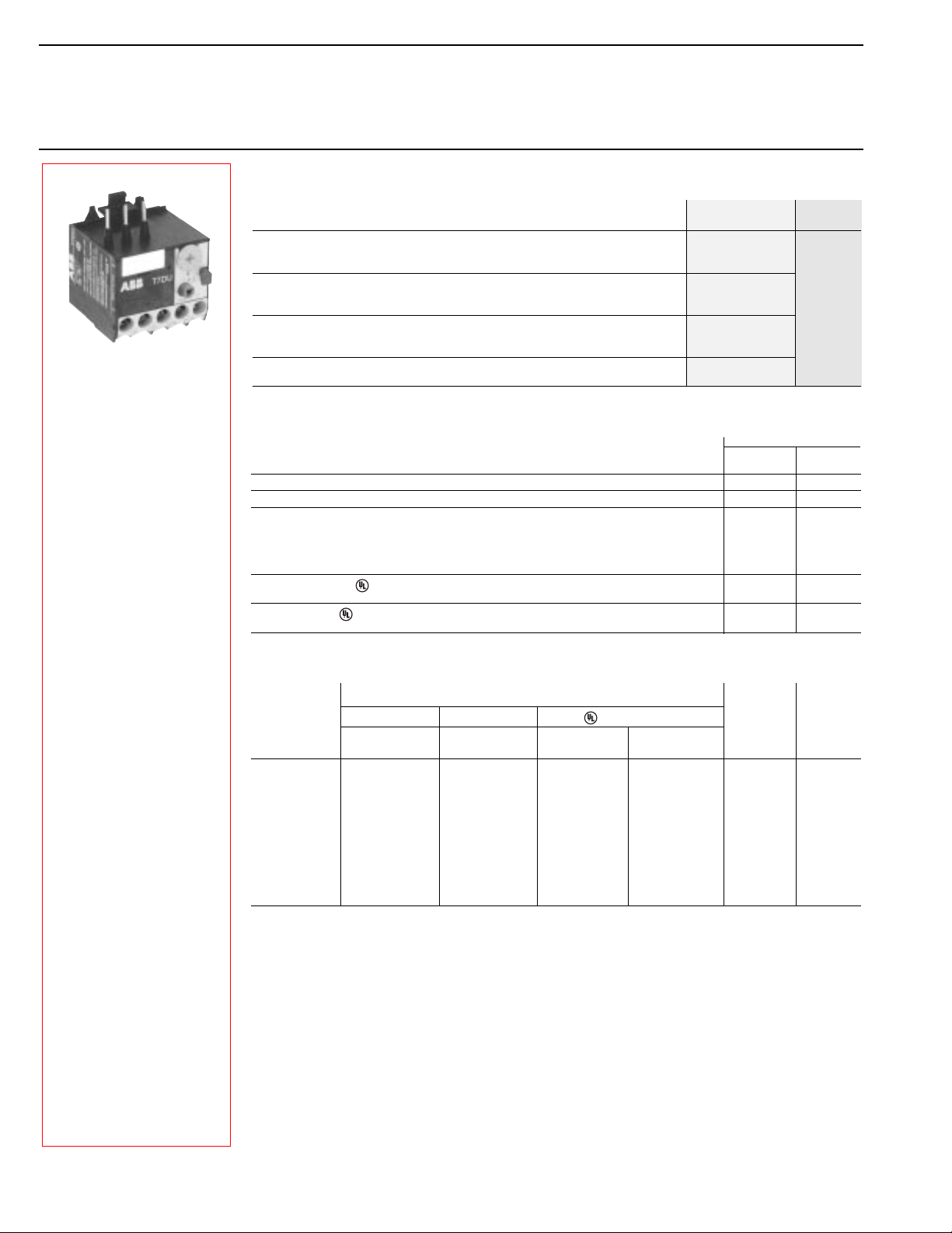
Thermal overload relay T7DU
For mini contactors
Selection
Thermal overload relay — for contactors B6,B7, BC6, BC7, B6S, B7S, VB6(7), VBC6(7),
VB6A(7A), VBC6A(/7A)
Setting range Catalog List
Amps number price
0.1–0.16 T7DU0.16
0.16–0.24 T7DU0.24
0.24–0.4 T7DU0.4
0.4–0.6 T7DU0.6
0.6–1.0 T7DU1.0
1.0–1.6 T7DU1.6 $ 32
1.6–2.4 T7DU2.4
2.4–4.0 T7DU4.0
4.0–6.0 T7DU6.0
6.0–9.0 T7DU9.0
9.0–12.0 T7DU12.0
Loading capacity of auxiliary switches
Type T 7 DU
Rated operating voltage Ue/V
Thermal current A6 6
Rated operating current I
Pilot duty rating
General use
R
R
IEC / UL508
e
at AC-15 220/240 V A 1.5 1.5
at AC-15 380/415 V A 0.7 0.5
at AC-15 500 V A 0.5 0.3
at DC-15 220 V A 0.2 0.2
AC D300 D300
DC R300 R300
240V 1.5A 1.5A
600V 0.6A 0.6A
N.C. N.O.
95 – 96 97 – 98
V 500 / 300 500 / 300
Thermal overload relay T7DU
Setting range Short circuit protection (fuses, circuit breakers) Joule losses
Coordination Type 2 (IEC) Coordination Type 1(IEC) 600V, 5kA Resistance at upper
A – A A A
0.1–0.16 0.5 20 1 15A 62.3 1.6
0.16–0.24 1 20 1 15A 27 1.6
0.24–0.4 2 20 1 15A 11.7 1.9
0.4–0.6 2 20 1 15A 4.61 1.7
0.6–1.0 4 20 3 15A 1.66 1.7
1.0–1.6 6 20 6 15A 0.63 1.6
1.6–2.4 6 20 6 15A 0.27 1.6
2.4–4.0 10 20 15 15A 0.107 1.7
4.0–6.0 10 20 20 15A 0.049 1.8
6.0–9.0 10 20 35 15A 0.021 1.7
9.0–12.0 20 20 45 15A 0.010 1.4
gL/gG gL/gG
R
Fuse MCCB setting
per phase current
WW
per phase
AC 1000.1 — 10/98
2
Discount schedule MB
ABB Control Inc.
Page 2
Thermal overload relay T7DU
Technical data
Approvals and certifications
Type T7DU
Standards: (major international and European standards) IEC 947-4-1, UL 508
Approvals, certificates UL, CSA, PTB*...
Rated insulation voltage U
acc. to IEC 158-1, IEC 947-4-1 V 690V
acc. to IEC / UL 508 Ui/V 660V / 600V
Impulse withstand voltage U
acc. to IEC 947-4-1
Permissible ambient temperature
Climatic resistance according to IEC 68-2-3, IEC 68-2-30
Mounting position ±30° from vertical position
Resistance to shock Shock duration ms 10
*Critical shock
direction A1, A2 multiple of g 10
Resistance to vibrations —
(±1 mm, 50 Hz) multiple of g
Mounting • on contactor Hooking underneath the contactor, screwing on its main terminal
Terminal types and connecting capacity
of main conductors (on motor side)
Terminals and auxiliary conductors
Protection degree to IEC 947-1/EN 60 947-1 All terminals are safe from finger-touch and touch by the
i
imp kV
• for storage °C -40 to 70
• with compensated operation °C
– open °C -25° to + 50°C
– enclosed °C -25° to + 40°C
• Screw terminals (screw size)
• connection cross sections
• Screw terminals (screw size)
• connection cross sections
• with self-disengaging clamping piece M3.5
• with terminal block —
• with busbar or cable lugs —
• single-core or stranded Awg/mm
• flexible with connector sleeve mm
• with self-disengaging clamping piece M3.5
• single-core or stranded Awg/mm
• flexible with connector sleeve mm
Side by side mounting distance, 5mm
2
2
2
2
back of the hand in accordance with VDE 0106, Part 100
Power pole technical data
Number of poles 3
Setting ranges see order codes
Tripping class acc. to IEC 947-4-1/EN 60 947-4-1 10A
Frequency limit Hz 0 – 400
Switching frequency
without early tripping
* submitted
up to 15 ops./h or 60 ops./h with 40% on load factor
if starting current not higher than 6 x I
and starting time not longer than 1s
EN 60 947-4-1
6
not horizontally, not upside down
2 x 18 – 14 / 2 x 0.75 – 2.5
2 x 0.5 – 1.5
2 x 18 – 14 / 2 x 0.75 – 2.5
2 x 0.5 – 1.5
n
Approvals
UL CSA EZU PTB GL LRS
USA Canada Czech. Republic Germany Germany Great Britain
■■❏❏❏❏
Legend:
■ Standard design approved: identification plates bear the approval marks if it is mandatory
❏ Submitted for approval
AC 1000.1 — 10/98
ABB Control Inc.
3
 Loading...