

Page 1
Page 2

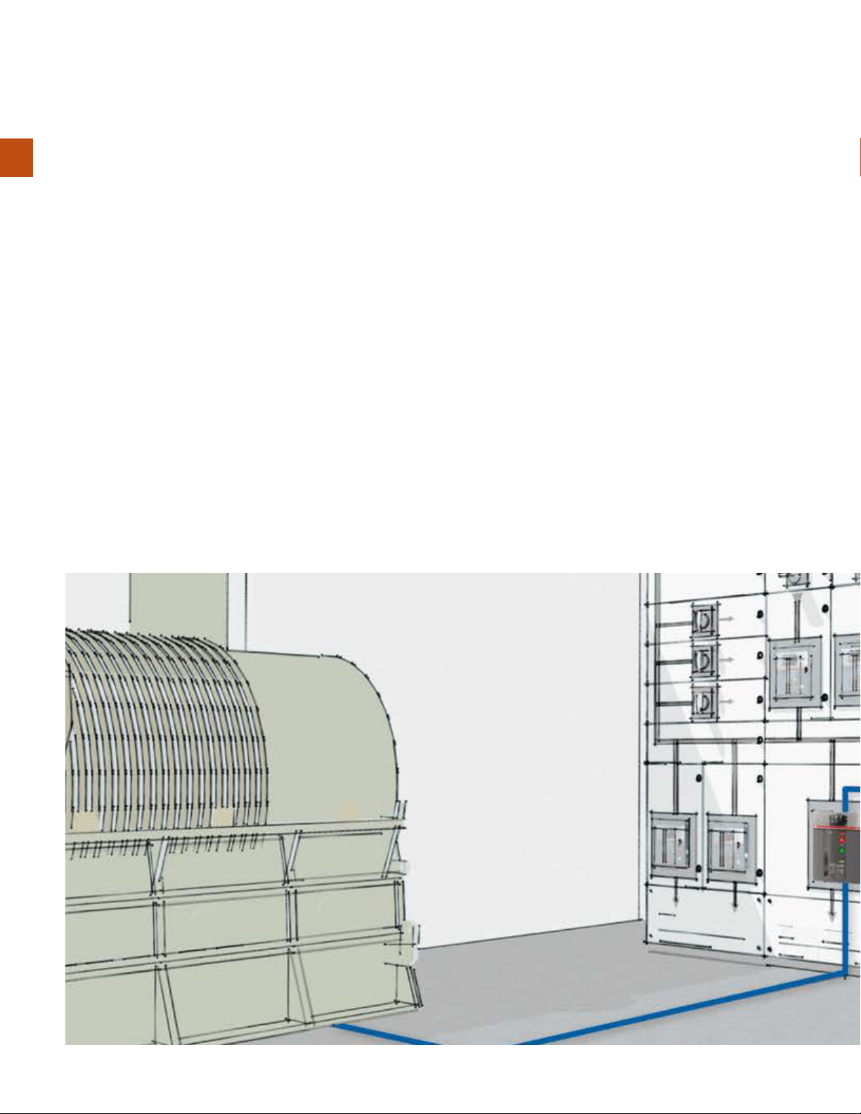
Page 3
Page 4
Page 5
Page 6
Page 7
Page 8
Page 9
Page 10
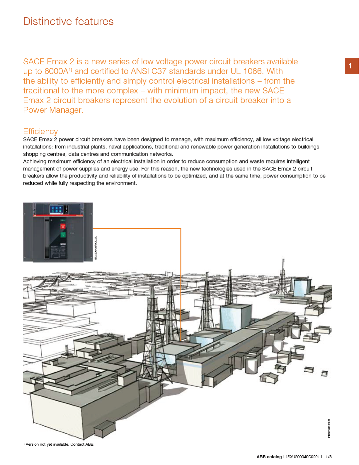
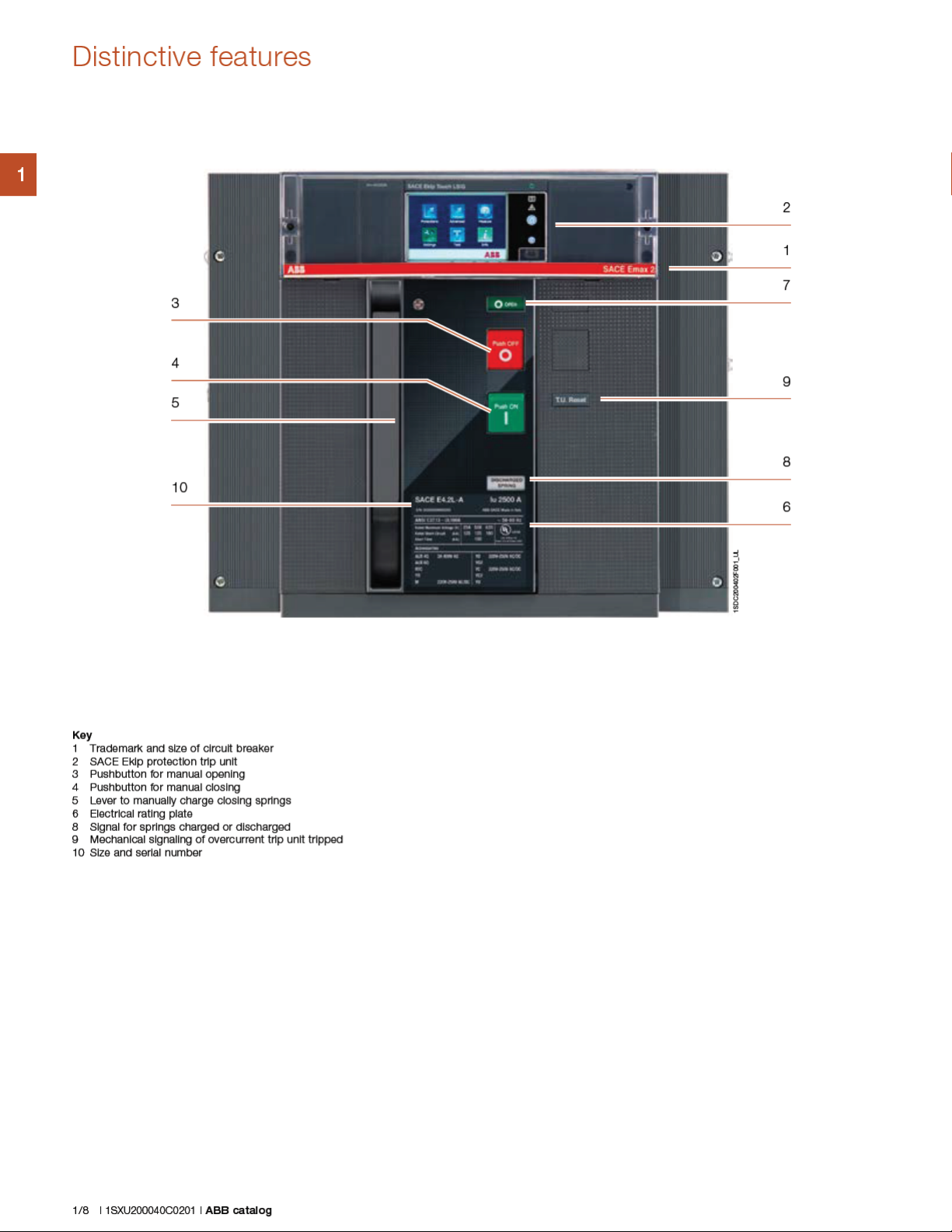
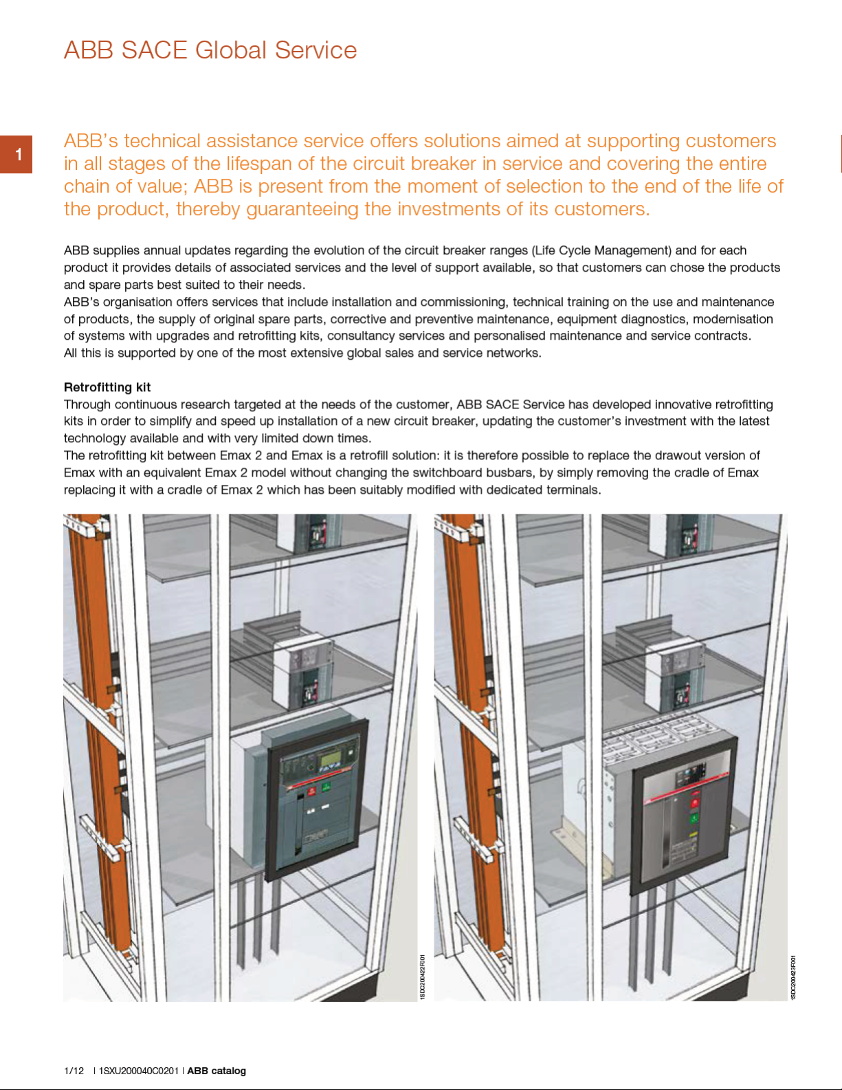
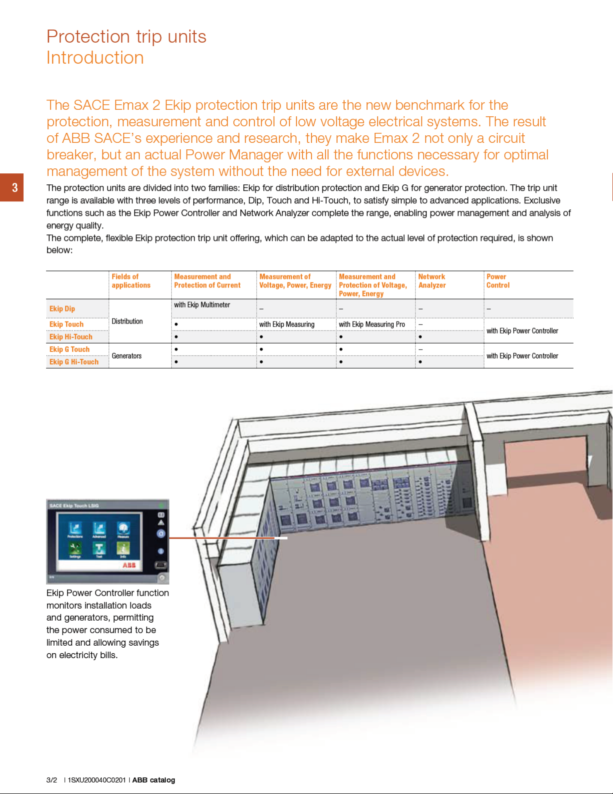
Distinctive features
1
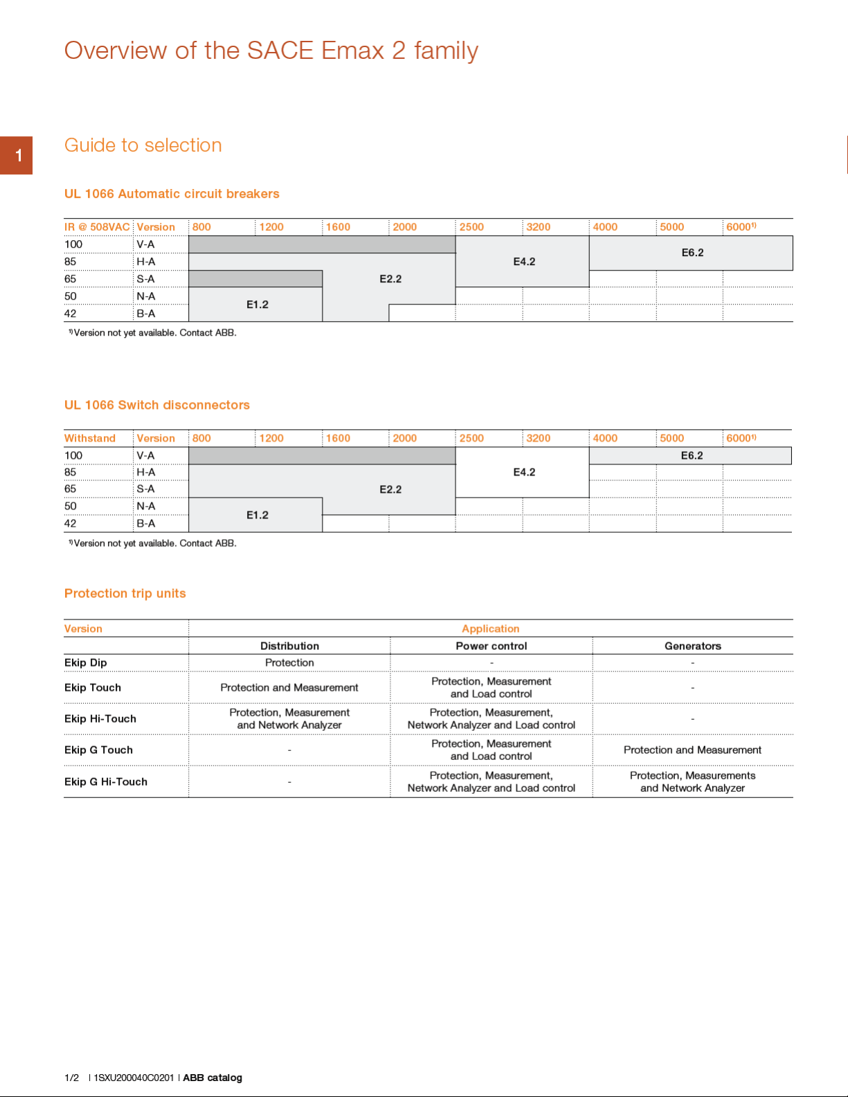
Performance
The SACE Emax 2 for UL 1066 range is made up of 4 sizes: E1.2, E2.2, E4.2 and E6.2 up to 6000A1), which enable switchgear of
compact dimensions and high ratings to be built with busbars of reduced length and cross-section.
The protection trip units, auxiliary connections and main accessories are the same throughout the range to simplify design and
installation. Furthermore, the sizes from E2.2 to E6.2 have the same height and depth.
The rating levels are updated and uniform throughout the sizes to meet the demands and needs of today’s installations, from
42kA to 150kA at 508V and to standardize switchgear projects.
High short-time withstand currents, together with the efficiency of the protection functions, guarantee complete selectivity in all
situations. Accurate design and choice of materials enable optimization of the overall dimensions of the circuit breaker. In this way
switchgear of compact dimensions can be built and outstanding savings at the same performance can be obtained.
In particular:
– E1.2 offers 1200A with an interrupting rating of up to 65kA and a short-time withstand current of 50kA in an extremely
compact structure. In the three and four pole version, it offers the sturdiness of SACE Emax with reduced dimensions and
enables switchgear of 65kA to be built in units of 16 inches, which is indispensable in places where reduced dimensions are
essential, such as naval and offshore installations.
– E2.2 enables ratings of up to 2000A to be achieved in switchgear with a width of 16 inches when the three pole version is
used. In addition, it provides an interrupting rating of up to 100kA and withstand current of up to 85kA.
– E4.2 is the new standard for circuit breakers up to 3200A. It is designed for interrupting ratings up to 100kA at 508V and
short-time withstand currents of up to 100kA without the need for particular precautions.
– E6.2 is the top of the range, with an interrupting rating of 100kA, a withstand rating of up to 100kA and a structure that
allows 6000A
1)
to be reached, even in complex installation conditions.
1)
Version not yet available. Contact ABB.
1/6 | 1SXU200040C0201 | ABB catalog
Page 11
Page 12
Page 13

Page 14

Page 15
Page 16
Page 17

The Ranges
SACE Emax 2 power circuit breakers UL 1066 2/2
SACE Emax 2 switch disconnectors UL 1066 2/4
SACE Emax 2 power circuit breakers IEC 60947 2/6
SACE Emax 2 switch disconnectors IEC 60947 2/8
SACE Emax 2 power circuit breakers and switch disconnectors
for applications up to 1150V AC IEC 60947 2/10
SACE Emax 2 other versions 2/12
2
ABB catalog | 1SXU200040C0201 | 2/1
Page 18

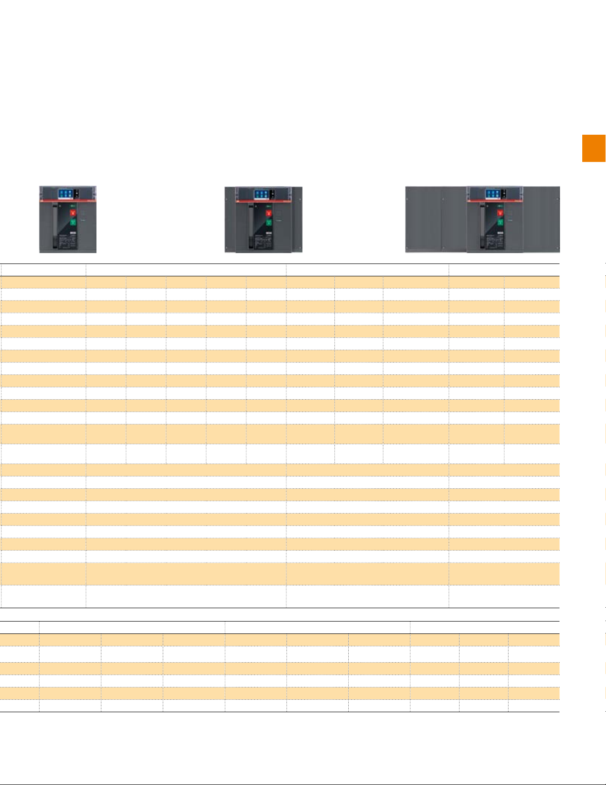
SACE Emax 2 power circuit breakers UL 1066
Common data
Rated maximum voltage [V] 635
Rated voltage [V] 600
2
Test voltage (1min. 50/60 Hz) [kV] 2.2
Frequency [Hz] 50 - 60
Number of poles 3 - 4
Version Fixed (F) - Drawout (W)
1SDC200424F001_UL
SACE Emax 2 for UL1066
Performance levels
Current
Neutral pole current-carrying capacity for 4 pole CBs
Interrupting rating at
rated maximum voltage
Rated short time current
Trip times Break time with fault current < rated short
Overall dimensions
Weights
254 V [kA] 42 50 65
508 V [kA] 42 50 65
635 V [kA] 42 42 42
time current
Break time with fault current > rated short
time current
H - Fixed [in/mm] 11.65 / 296
D - Fixed [in/mm] 7.20 / 183
W - Fixed 3p [in/mm] 8.27 / 210
W - Fixed 4p/4p full size [in/mm] 11.02 / 280
H - Draw out [in/mm] 14.33 / 363.5
D - Draw out [in/mm] 11.06 / 281
W - Draw out 3p [in/mm] 10.94 / 278
W - Draw out 4p/4p full size [in/mm] 13.70 / 348
Fixed 3p / 4p / 4p full size [lbs/Kg] 30.9/35.3 lbs - 14/16 kg
E1.2
B-A N-A S-A
[A] 800 800 250
[A] 1200 1200 400
[A] 800
[A] 1200
[A]
[A]
[%Iu] 100 100 100
[kA] 42 50 50
[ms] 40 40 40
[ms] 25 25 25
SACE Emax 2 for UL1066
Mechanical life with regular ordinary
maintenance prescribed by the
manufacturer
Electrical life with regular ordinary
maintenance prescribed by the
manufacturer
1)
Version not yet available. Contact ABB.
2/2 | 1SXU200040C0201 | ABB catalog
Draw out 3p / 4p / 4p full size [lbs/Kg] 90.4/102.5 lbs - 41/46.5 kg
E1.2
[A] < 800 800 1200
[No. cycles x 1000] 20 20 20
Frequency [Cycles/Hour] 60 60 60
508 V [No. cycles x 1000] 8 8 7
635 V [No. cycles x 1000] 8 8 6.5
Frequency
[Cycles/Hour] 30 30 30
Page 19
2
1SDC200425F001_UL
1SDC200426F001_UL
E2.2 E4.2 E6.2
B-A N-A S-A H-A V-A S-A H-A V-A H-A V-A
1600 1600 800 800 250 2500 2500 800 4000 4000
1)
6000
100 100 100 100 100 100 100 100 50-100 50-100
42 50 65 85 100 65 85 100 85 100
42 50 65 85 85 65 85 100 85 100
40 40 40 40 40 40 40 40 40 40
25 25 25 25 25 25 25 25 25 25
14.61/371 14.61/371 14.61/371
15.47/393 15.47/393 15.47/393
1SDC200427F001_UL
1)
115/148 lbs - 52/67 Kg
up to 1600A: 128/150 lbs - 58/68 Kg
2000A: 135/239lbs - 61/108kg
Up to 2500A: 161/203 lbs - 73/92 kg
3200A: 201/256 lbs - 91/116 kg
Up to 2500A: 261/325 lbs - 118/147 kg
3200A: 300/377 lbs - 136/171 kg
314/360/406 lbs
142/163/184 kg
486/554/620 lbs
220/251/281 kg
E2.2 E4.2 E6.2
< 1600 1600 2000 < 2500 2500 3200 4000 5000 6000
60 60 60 60 60 60 60 60 60
15 12 10 10 8 7 4 3 2
30 30 30 20 20 20 10 10 10
ABB catalog | 1SXU200040C0201 | 2/3
1)
Page 20
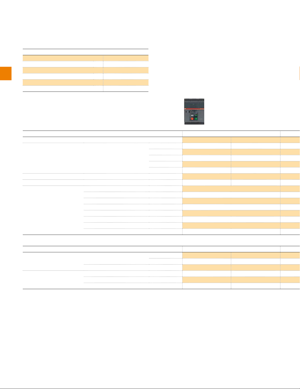
SACE Emax 2 switch disconnectors UL 1066
Common data
Rated maximum voltage [V] 635
Rated voltage [V] 600
2
Test voltage (1min. 50/60 Hz) [kV] 2.2
Frequency [Hz] 50 - 60
Number of poles 3 - 4
Version Fixed (F) - Drawout (W)
1SDC200428F001_UL
SACE Emax 2 for UL1066
Performance levels
Current
Neutral pole current-carrying capacity for 4 pole CBs
Rated short time current
Overall dimensions
1) Rated short-time current is equal to 42kA at 635V.
SACE Emax 2 for UL1066
Mechanical life with regular ordinary
maintenance prescribed by the
manufacturer
Electrical life with regular ordinary
maintenance prescribed by the
manufacturer
1) Version not yet available. Contact ABB.
H - Fixed [in/mm] 11.65 / 296
D - Fixed [in/mm] 7.20 / 183
W - Fixed 3p [in/mm] 8.27 / 210
W - Fixed 4p/4p full size [in/mm] 11.02 / 280
H - Draw out [in/mm] 14.33 / 363.5
D - Draw out [in/mm] 11.06 / 281
W - Draw out 3p [in/mm] 10.94 / 278
W - Draw out 4p/4p full size
Frequency [Cycles/Hour] 60 60
508 V [No. cycles x 1000] 8 7
635 V [No. cycles x 1000] 8 6.5
Frequency
E1.2
B-A N-A
[A] 800 800
[A] 1200 1200
[A]
[A]
[A]
[%Iu] 100 100
[kA] 42 50
[in/mm] 13.70 / 348
E1.2
[A] 800 1200
[No. cycles x 1000] 20 20
[Cycles/Hour] 30 30
1)
2/4 | 1SXU200040C0201 | ABB catalog
Page 21
2
1SDC200429F001_UL
1SDC200430F001_UL
E2.2 E4.2 E6.2
N-A S-A V-A S-A H-A V-A L-A
1600 800 800 2500 2500 800 4000
1)
100 100 100 100 100 100 50-100 50-100
50 65 85 65 85 100 100 100
14.61/371 14.61/371 14.61/371
15.47/393 15.47/393 15.47/393
407/16.02 21.69/551 36.57/929 - 42.09/1069
E2.2 E4.2 E6.2
< 1600 1600 2000 < 2500 2500 3200 4000 5000 6000
1SDC200431F001_UL
60 60 60 60 60 60 60 60 60
15 12 10 10 8 7 4 3 2
30 30 30 20 20 20 10 10 10
ABB catalog | 1SXU200040C0201 | 2/5
Page 22
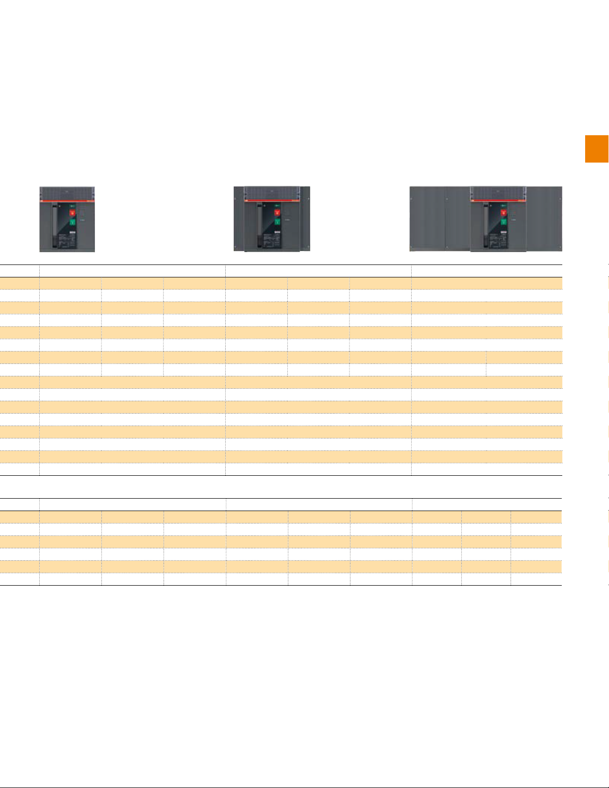
SACE Emax 2 power circuit breakers IEC 60947
Common data
Rated service voltage Ue [V] 690
Rated insulation voltage Ui [V] 1000
2
Rated impulse withstand voltage Uimp [kV] 12
Frequency [Hz] 50 - 60
Number of poles 3- 4
Version Fixed (F) - Drawout (W)
Isolation behaviour IEC 60947-2
1SDC200424F001_UL
SACE Emax 2 for IEC 60947
Performance levels
Rated uninterrupted current Iu @ 40°C
Neutral pole current-carrying capacity for 4-pole CBs
Rated ultimate short-circuit
breaking capacity Icu
Rated service short-circuit breaking capacity Ics
Rated short-time withstand
current Icw
Rated short-circuit making
capacity (peak value) Icm
Utilization category (according to IEC 60947-2)
Breaking time
Dimensions
Weights (CB with trip unit and
current sensor)
1) Ics: 50kA for 400V…440V voltage; 2) Ics: 125kA for 400V...440V voltage; 3) E4.2H 3200A: 66kA Icw (3s)
400-415 V [kA] 42 50 66 150
440 V [kA] 42 50 66 130
500-525 V [kA] 42 42 50 100
690 V [kA] 42 42 50 45
(1s) [kA] 42 42 50 15
(3s) [kA] 24 24 36 -
400-415 V [kA] 88 105 145 330
440 V [kA] 88 105 145 286
500-525 V [kA] 88 88 105 220
690 V [kA] 88 88 105 132
I<Icw [ms] 40 40 40 40
I>Icw [ms] 25 25 25 10
H - Fixed/Withdrawable [mm] 296/363.5 296/363.5 296/363.5 296/363.5
D - Fixed/Withdrawable [mm] 183/271 183/271 183/271 183/271
W - Fixed 3p/4p/4p full size [mm] 210/280
W - Withdrawable 3p/4p/4p full size [mm] 278/348
Fixed 3p/4p kg 14/16
Withdrawable 3p/4p/4p full size
including fixed part
[A] 630 630 250 630
[A] 800 800 630 800
[A] 1000 1000 800 1000
[A] 1250 1250 1000 1250
[A] 1600 1600 1250
[A] 1600
[A]
[%Iu] 100 100 100 100
[%Icu] 100 100 100
kg 38/43
E1.2
B C N L
1)
B B B A
100
SACE Emax 2 for IEC 60947
Mechanical life with regular ordinary
maintenance prescribed by the
manufacturer
Electrical life with regular ordinary
maintenance prescribed by the
manufacturer
2/6 | 1SXU200040C0201 | ABB catalog
E1.2
[Iu] ≤ 1000 1250 1600 1250 L
[No. cycles x 1000] 20 20 20 20
Frequency [Oper./Hour] 60 60 60 60
440 V [No. cycles x 1000] 8 8 8 3
690 V [No. cycles x 1000] 8 6.5 6.5 1
Frequency
[Oper./Hour] 30 30 30 30
Page 23
2
1SDC200425F001_UL
1SDC200426F001_UL
E2.2 E4.2 E6.2
B N S H N S H V H V X
1600 800 250 800 3200 3200 3200 2000 4000 4000 4000
100 100 100 100 100 100 100 100 50-100 50-100 50-100
42 66 85 100 66 85 100 150 100 150 200
100 100 100 100 100 100 100 100
2)
100 100 100
42 66 66 85 66 66 85 100 100 100 120
42 50 50 66 50 66 75
3)
75 100 100 100
88 145 187 220 145 187 220 330 220 330 440
B B B B B B B B B B B
40 40 40 40 40 40 40 40 40 40 40
25 25 25 25 25 25 25 25 25 25 25
371/425 371/425 371/425 371/425 371/425 371/425 371/425 371/425 371/425 371/425 371/425
1SDC200427F001_UL
317/407 425/551 803/929/1069
41/53 56/70 109/125/140
54/99 110/136 207/234/260
E2.2 E4.2 E6.2
< 1600 1600 2000 2500 < 2500 2500 3200 4000 4000 5000 6300
60 60 60 60 60 60 60 60 60 60 60
15 12 10 8 10 8 7 5 4 3 2
30 30 30 30 20 20 20 20 10 10 10
ABB catalog | 1SXU200040C0201 | 2/7
Page 24
SACE Emax 2 switch disconnectors IEC 60947
Switch disconnectors, identified with the abbreviation “/MS”, are devices that satisfy the isolating specifications provided by
the IEC 60947-3 Standard. The switch disconnectors are derived from the corresponding automatic circuit breakers, and they
have the same dimensions and accessory options. This version differs from the automatic circuit breakers only because of the
absence of protection trip units.
2
Common data
Rated service voltage Ue [V] 690
Rated insulation voltage Ui [V] 1000
Rated impulse withstand voltage Uimp [kV] 12
Frequency [Hz] 50 - 60
Number of poles 3- 4
Version Fixed (F) - Drawout (W)
Isolation behaviour IEC 60947-3
1SDC200428F001_UL
SACE Emax 2 for IEC 60947 E1.2
Performance levels
Rated uninterrupted current Iu @ 40°C
Neutral pole current-carrying capacity for 4-pole CBs
Rated short-time withstand current
Icw
Rated short-circuit making capacity
(peak value) Icm
Utilization category (according to IEC 60947-3)
Dimensions H - Fixed / Withdrawable
(1s)
(3s)
400-415 V
440 V
500-525 V
690 V
D - Fixed / Withdrawable
W - Fixed 3p/4p/4p full size [mm] 210 / 280
W - Withdrawable 3p/4p/4p full size
[A] 630 250
[A] 800 630
[A] 1000 800
[A] 1250 1000
[A] 1600 1250
[A] 1600
[%Iu] 10 0 100
[kA] 42 50
[kA] 24 36
[kA] 88 105
[kA] 88 105
[kA] 88 105
[kA] 88 105
[mm] 296 / 363.5 296 / 363.5
[mm] 183 / 271 183 / 271
[mm] 278 / 348
B/MS N/MS
AC-23A AC-23A
SACE Emax 2 for IEC 60947
Mechanical life with regular
ordinary maintenance prescribed
by the manufacturer
Electrical life with regular
ordinary maintenance prescribed
by the manufacturer
2/8 | 1SXU200040C0201 | ABB catalog
Frequency [Oper./Hour] 60 60 60
440 V [No. cycles x 1000] 8 8 8
690 V [No. cycles x 1000] 8 6.5 6.5
Frequency [Oper./Hour] 30 30 30
E1.2
[Iu] < 1000 1000 1600
[No. cycles x 1000] 20 20 20
Page 25
The device, when in the open position, guarantees an isolating distance between the main contacts of the circuit breaker that is
sufficient to ensure that the installation downstream is not live.
Furthermore the switch disconnectors, if used with an external protection relay with maximum delay of 500ms, enable a
breaking capacity at a maximum rated operating voltage (Ue) equal to the value of rated short-time withstand current (Icw) for
one second.
2
1SDC200429F001_UL
E2.2 E4.2 E6.2
B/MS N/MS H/MS N/MS H/MS V/MS H/MS
160 0 800 800 3200 3200 2000 4000
100 100 100 100 100 100 50-100
42 66 85 66 85 100 100
42 50 66 36 66 75 100
88 145 187 145 187 220 220
88 145 187 145 187 220 220
88 145 187 145 187 220 220
88 145 187 145 187 220 220
AC-23A AC-23A AC-23A AC-23A AC-23A AC-23A AC-23A
371 / 425 371 / 425 371 / 425 371 / 425 371 / 425 371 / 425 371 / 425
270 / 383 270 / 383 270 / 383 270 / 383 270 / 383 270 / 383 270 / 383
317 / 407 425 / 551 803 / 929 / 1069
E2.2 E4.2 E6.2
< 1600 1600 2000 2500 < 2500 2500 3200 4000 4000 5000 6300
1SDC200430F001_UL
1SDC200431F001_UL
60 60 60 60 60 60 60 60 60 60 60
15 12 10 8 10 8 7 5 4 3 2
30 30 30 30 20 20 20 20 10 10 10
ABB catalog | 1SXU200040C0201 | 2/9
Page 26

2
2/10 | 1SXU200040C0201 | ABB catalog
Page 27

Protection trip units
Introduction 3/2
Architecture 3/4
Protection trip units for power distribution
Ekip Dip 3/6
Ekip Touch 3/10
Ekip Hi-Touch 3/20
Protection trip units for generators
Ekip G Touch 3/24
Ekip G Hi-Touch 3/29
Protection trip units for power control
Ekip Power Controller 3/32
Technical characteristics for protection trip units
Protection functions 3/38
Measurement functions 3/48
3
ABB catalog | 1SXU200040C0201 | 3/1
Page 28
Page 29
Page 30
Protection trip units
Architecture
All SACE Emax 2 circuit breakers are equipped with protection trip units that are
interchangeable from the front with just a few, simple operations by the customer.
There is no need to dismantle the circuit breaker or access any internal or sensitive
parts.
3
This enables personalization of the functions available, even during commissioning or when the circuit breaker has already been
installed. In particular, SACE Ekip consists of:
– Protection trip unit, available with different interfaces and versions that range from basic to more complete; it contains a
latest generation microprocessor that performs all the functions of protection and control.
– Ekip Measuring Module, connected internally to Emax 2, performs voltage, power and energy measurements with high
accuracy without requiring any external connection or voltage transformer. The Ekip Measuring Pro version also performs
all protection functions based on voltage and power without the need for external units, thereby simplifying design and
construction of the system.
– Interchangeable rating plug enables all protection thresholds to be adjusted according to the rated current, increasing
flexibility for the customer. It is useful in installations that are prepared for future development or in cases in which the power
supplied may be limited temporarily.
– Main board is the mechanical housing of the trip unit, which includes a micro-controller for measuring currents and the
self-protection functions. The separation of main board and protection trip unit ensures excellent reliability and immunity to
conducted and radiated emissions. Integrated new generation Rogowski sensors, which are sensitive to the true r.m.s. value
of the current, guarantee high accuracy of both measurements and protection.
3/4 | 1SXU200040C0201 | ABB catalog
1SDC200444F001
Page 31

All protection trip units of the SACE Emax 2 family are self-powered by current
that flows through the circuit breaker. They guarantee excellent reliability due to a
system of self-controlled internal connections. The setting, testing and downloading
of reports can be carried out directly from a Smartphone, Tablet or PC.
Easily installed cartridge type modules enable the units to be integrated into the most complex systems. Additional functions
can be created, such as:
– Synchrocheck, checks the synchronization between two busbar systems before enabling circuit breaker closing;
– Communication with all supervision systems is available in the Modbus, Profibus and DeviceNet protocols as well as the
modern Modbus TCP, Profinet and EtherNet/IP protocols;
– Integration into Smart Grids according to the IEC61850 standard (used to communicate with high and medium voltage
substation automation systems), without the need for an external converter;
– Multi-voltage supply module, which enables the protection trip unit and modules present to be supplied with any auxiliary
voltage available in direct or alternating current;
– Programmable logic management with Ekip Signaling modules that make a high number of electrical input and output
contacts available;
– Logical interlocks between circuit breakers, which can be made with the Ekip Link proprietary communication protocol,
avoiding complex wiring because of the transmission of all signals via bus.
3
ABB catalog | 1SXU200040C0201 | 3/5
1SDC200445F001
Page 32

Protection trip units for power distribution
Ekip Dip
Characteristics
Ekip Dip is the new protection trip unit of the SACE Emax 2 family for all
applications in which high accuracy and reliable protection against overcurrent are
required. Ekip Dip offers a complete set of standard protection functions. Dedicated
LEDs allow the fault that caused tripping to be determined.
3
The unit is available in the following versions:
– Ekip Dip LI
– Ekip Dip LSI
– Ekip Dip LSIG
1
2
3
Key:
1. Power-on LED for Signaling correct operation
(watchdog)
2. LEDs for alarm Signaling of L, S, I and G
protection functions and diagnostics
3. Dip switches for setting the protection functions
4
5
6
1SDC200446F001
4. Dip switches for setting the network frequency
and neutral protection device
5. Pushbutton for test and for indicating the cause
of tripping
6. Test and programming connector
3/6 | 1SXU200040C0201 | ABB catalog
Page 33

Page 34

Protection trip units for power distribution
Ekip Dip
Measurements
The Ekip Dip unit measures phase and neutral current with great accuracy: 1% including the current transformers in the 0.2 ...
1.2 In range (class 1 in accordance with IEC 61557-12). Using the current sensors in the circuit breaker and without the need to
install an external measuring system, it is possible to view the measurements from the display on the front of the Ekip Multimeter
and Ekip Control Panel.
Ekip Dip also records the characteristics of the circuit breaker, to enable a rapid analysis during troubleshooting or maintenance:
– Maximum and average current values per phase;
3
– Date, time, fault current per phase and type of protection tripped over the last 30 trips;
– Date, time and type of operation of the last 200 events (for example: opening/closing of the circuit breaker, pre-alarms, editing
settings);
– Number of mechanical and electric operations of the circuit breaker;
– Total operating time;
– Contact wear (endurance);
– Date and time of the last maintenance carried out, in addition to the estimate of the next maintenance required;
– Circuit-breaker identifying data: type, serial number, firmware version, name of the device as assigned by the user.
The values can be displayed on the front of the Ekip Multimeter or Ekip Control Panel or by Ekip Connect software on a
Smartphone, Tablet or PC by using the communication units Ekip T&P or Ekip Bluetooth.
Watchdog
All the protection trip units of the SACE Emax 2 family ensure high reliability owing to an electronic circuit that periodically controls
the continuity of the internal connections, such as trip coil, rating plug and each current sensor (Ansi 74). In the event of a
malfunction, the LEDs indicate the corresponding alarm to enable the fault to be identified rapidly. Furthermore, Ekip Dip detects
and indicates that the circuit breaker has been opened because one of the protection functions has been tripped (Ansi BF code).
In order to preserve the correct operation of the unit, Ekip Dip is also provided with self-protection against abnormal temperature
(OT) inside the protection trip unit. The user can set it to open the circuit breaker or to merely indicate an alarm.
User interface
Ekip offers a great variety of thresholds and trip times, the protections can be set by dip-switches. Up to 5 LEDs are also
available (depending on the version) to indicate correct operation or alarms. The interface always enables the status of the
installation to be identified clearly and quickly:
– correct operation (green LED)
– overcurrent pre-alarms or alarms
– presence of self-control functions alarms
– maintenance interval expired
– indication of tripped protection after a fault
The protection tripped indication is activated by pressing the iTest key, and operates without the need of an external power
supply because a battery is installed inside the unit.
Communication
The Ekip Bluetooth wireless communication unit enables the operator to interact with the protection trip unit by computer,
Smartphone or Tablet. In fact, the free Ekip Connect software for Smartphones, Tablets and PC, enables measurements and
fault data to be read along with alarm status and information from the circuit breaker to be displayed. It is also possible to set
parameters such as date, time and thermal memory and for records to be reset.
3/8 | 1SXU200040C0201 | ABB catalog
Page 35

Test function
The test port on the front of the protection trip unit can be used to run circuit breaker tests by connecting one of the following
devices:
– Ekip TT to run the trip test, the LEDs test and check absence of alarms detected by the watchdog function;
– Ekip T&P to permit not only the trip test and LEDs test but also to run the test of the individual protection functions and save
the relative report;
– ITest key that is pressed to run the battery test when the circuit breaker is disconnected.
Supply
The Ekip Dip protection trip unit does not require an external supply for the protection functions or for the alarm indication
functions because it is self-supplied by the current sensors installed on the circuit breaker. A three-phase 100A current suffices
to activate the LED indications.
The Ekip Supply module enables an auxiliary supply to be easily connected and is able to receive both a direct current supply
(24-48VDC or 110-240VDC) and an alternating current (110-240VAC) to activate additional functions such as:
– G protection at values below 100A or below 0.2 In;
– connecting to external devices such as Ekip Multimeter and Ekip Control Panel;
– recording the number of operations.
The Ekip Dip protection trip unit also has a battery that enables the indication of the cause of the fault to be viewed for an unlimited
time after tripping. In addition to that, the battery enables date and time to be maintained and updated, thus ensuring the chronology
of the events. On the other hand, when the unit is switched off, the battery test can be run by simply pressing the iTest key.
Supply Ekip Supply
Nominal voltage 24-48V DC 110-240V AC/DC
Voltage range 21.5 - 53V DC 105-265V AC/DC
Rated power (including modules) 10W max. 10W max.
Inrush current ~10 A for 5 ms ~10 A for 5 ms
3
Whenever cartridge modules are not used in the terminal box area, the trip unit can be supplied by means of a galvanically
isolated 24V DC auxiliary voltage.
ABB catalog | 1SXU200040C0201 | 3/9
Page 36

Protection trip units for power distribution
Ekip Touch
Characteristics
Ekip Touch is the new protection trip unit for SACE Emax 2 that provides a
complete series of protections and high accuracy measurements of all electric
parameters and can be integrated perfectly with the most common automation and
supervision systems.
3
The simple and intuitive touch screen interface enables the operator to access
all the information and settings rapidly and easily by minimizing installation and
commissioning time.
The unit is available in the versions:
– Ekip Touch LI
– Ekip Touch LSI
– Ekip Touch LSIG
1
Key:
1. Wide high-resolution color touch screen display
2. Power-on LED to indicate correct operation
(watchdog)
3. Pre-alarm LED
2
3
4
5
6
7
1SDC200466F001
4. Alarm LED
5. Home pushbutton to return to home page
6. Pushbutton for test and indicating cause of trip
7. Test and programming connector
3/10 | 1SXU200040C0201 | ABB catalog
Page 37

Page 38

Page 39

Page 40

Page 41

Measurements
Measurements and meters
All versions of the Ekip Touch unit measure the RMS value of the currents of
the three phases (L1, L2, L3) and of neutral (Ne) with 1% accuracy in the 0.2 to
1.2 In range (class 1 in accordance with IEC 61557-12). The complete range of
measurement is from 0.03 to 16x In, where In is the value of the rating plug.
The display shows the current of the most loaded phase both in numeric and
analogue format on an ammeter with a 0-125% In scale for rapid identification of
the load of the circuit breaker.
1SDC200468F001
Alternatively, bar graphs that show the currents of the three phases and of neutral
on a 0-125% In scale in addition to the numeric value of the most loaded phase
can be selected as the default page. The bar graphs are yellow in the event of a
pre-alarm and red in the event of an overload to enable an irregular condition to be
identified immediately.
Where applicable, the measurement of the ground fault current is shown on a
dedicated page. The ammeter can operate both in self-supplied mode and with
auxiliary voltage. In the latter case, the display always has back lighting and the
ammeter is also active at currents below 100A.
1SDC200469F001
3
1SDC200470F001
Adding the Ekip Measuring or Ekip Measuring Pro module to Ekip Touch enables
Ekip Touch to be used as a multimeter to measure the values of:
– Voltage: phase-phase, phase-neutral (accuracy 0.5%);
– Power: active, reactive, apparent (accuracy 2%);
– Energy: active, reactive, apparent (accuracy 2%);
– Frequency (accuracy 0.2%);
– Power factor by phase and total;
– Peak factor.
Maximum values and values register
The Ekip Touch unit is able to supply the measurement trend of certain parameters
over a settable period of time such as: average power, maximum power,
maximum and minimum current, maximum and minimum voltage. The values of
the last 24 time intervals are recorded in the unit with a relative timestamp and
can be consulted directly from the display or remotely using one of the available
communication protocols. The communication can also be used to synchronize the
recording time interval.
Data logger
Ekip Touch is always supplied with the exclusive Data Logger (register) function
that stores with high sampling frequency the instantaneous values of all the
measurements in two memory buffer registers. The data can be easily downloaded
by the Ekip Connect unit and transferred to any personal computer. This enables the
current and voltage waveforms to be analyzed for rapid fault analysis. The function
continuously stores and stops recording, with a selectable delay, whenever the event
set by the user occurs (e.g. trip or alarm). In this manner, it is possible to analyze the
complete evolution of the fault: from the start to its complete elimination.
ABB catalog | 1SXU200040C0201 | 3/15
Page 42

Protection trip units for power distribution
Ekip Touch
Information on trip and opening data
If a trip occurs, Ekip Touch stores all the information that is required for rapid
identification and elimination of the causes:
– Protection tripped
– Opening data (current, voltage or frequency)
– Time-stamping (data, time and consecutive opening number)
3
If the iTest key is pressed, the trip unit displays all these data directly on the display.
No auxiliary supply is required. The information is also available to the user with the
circuit breaker open or without current flow, due to the battery installed inside the unit.
Maintenance indicators
A complete set of information about the circuit breaker and its operation is available
for effective fault analysis and preventive scheduling of maintenance. All the
information can be seen from the display or from a PC using a communication unit.
In particular:
– Date, time, fault current by phase and type of protection tripped over the last 30
trips;
– Date, time and type of operation of the last 200 events (example: opening/closing
of the circuit breaker, pre-alarms, editing of settings, ect.);
1SDC200471F001
– Number of operations of the circuit breaker: divided into mechanical operations
(no current), electrical operations (with current) and protection function (trip);
– Contact wear (enduarnce) estimated in function of the number and type of
openings;
– Total operating time of the circuit breaker with circulating current;
– Date and time of the last maintenance session, scheduling of the next
maintenance session;
– Circuit-breaker identifying data: type, serial number, firmware version, device
name assigned by the user.
3/16 | 1SXU200040C0201 | ABB catalog
All the information can be viewed directly from the display and from a Smartphone,
Tablet (with Ekip Bluetooth) or PC using the front port of the trip unit or the system
communication.
Page 43

Watchdog
All of the trip units in the SACE Emax 2 family ensure high reliability because of an electronic circuit that periodically controls
continuity of the internal connections, such as trip coil, rating plug and each current sensor (Ansi 74). In the event of an alarm,
a message is shown on the display, and if it is set during the installation phase, the trip unit can command the opening of
the circuit breaker. If a protection function intervenes, Ekip Touch always checks that the circuit breaker has been opened by
auxiliary contacts that indicate the position of the main contacts. Otherwise, Ekip Touch indicates an alarm (ANSI BF code Breaker Failure) to be used to command the opening of the circuit breaker located upstream.
Ekip also contains self-protection that preserves the correct operation of the unit against abnormal temperatures (OT) inside
the protection trip unit. The user disposes of the following indications or controls:
– “Warning” LED for temperature below -4°F/-20°C or above 158°F/70°C, at which the trip unit operates correctly with the
display switched off
– “Alarm” LED for temperature outside the operating range, at which the trip unit commands the opening of the circuit breaker
(if set during the configuration phase).
User interface
All Ekip Touch operations are simple and intuitive due to the wide graphic color
touchscreen display. For example, all the main information is listed on one page
(settable by default), thus enabling the state of the installation to be identified rapidly:
maximum current, maximum voltage, active, reactive, apparent power and energy.
In addition, the use of Ekip Touch is further simplified by the possibility of scrolling
through the menu and reading the alarms in one of the languages that can be set
directly from the display: Italian, English, German, French, Spanish, Portuguese,
Chinese, Russian, Turkish and Thai.
The home pushbutton enables you to return, at any moment, to the main page and
1SDC200472F0011SDC200473F001
the iTest key enables the information to be viewed after a circuit breaker trip or test.
3
As in the previous generation of trip units, a password system is used to manage
“Read” or “Edit” modes. The default password, 00001, can be edited by the user.
The protection parameters (curve and trip thresholds) are settable in “Edit” mode
whereas it is always possible to consult the information in “Read” mode.
On the front of the trip unit there are also two LEDs: a pre-alarm LED (square yellow
LED) and an alarm LED (red triangular LED); a message on the display always
accompanies the flashing of the LEDs for clear identification of the type of event.
The list of all the alarms active at that moment can be viewed by simply touching
the display on the white strip in the bottom left of the alarms zone.
Ekip Touch is also supplied with a front port that permits a temporary connection to
devices for test, supply or communication (for example Ekip T&P).
ABB catalog | 1SXU200040C0201 | 3/17
Page 44

Protection trip units for power distribution
Ekip Touch
Communication
Communication modules that can be installed inside the circuit breaker enable Ekip Touch to be integrated into the most
modern supervision systems with protocols:
– IEC 61850
– Modbus TCP
– Modbus RS-485
– Profibus
3
– Profinet
– DeviceNet
– EtherNet/IP
The integration into communication systems enables measurements, statuses and alarms to be programmed and viewed by
remote functions. If the circuit breaker has to be opened and closed remotely, the Ekip Com Actuator module can be installed
in the circuit breaker front, in the right-hand accessories chamber.
For each circuit breaker, several communication modules with different protocols can be used simultaneously; for example, this
enables the circuit breaker to be connected to the Ekip link system to obtain local supervision from the front of the switchgear
and to simultaneously integrate it into a communication network. In addition, for applications requiring very high reliability, up
to two modules of the same protocol can be inserted by use of the redundant version that enables two different addresses to
communicate on the same bus.
Test function
For testing the circuit breaker, it is possible to use the test port and the iTest key positioned on the front of the protection trip
unit. The available functions are:
– trip test, test of the display and of the LEDs and check of absence of alarms detected by the watchdog function using Ekip
TT (always supplied with Ekip Touch);
– test of the single protection functions and saving of the report, in addition to the trip test and test of the display, using Ekip
T&P;
– test of the battery with the circuit breaker switched off by pressing the iTest key.
3/18 | 1SXU200040C0201 | ABB catalog
Page 45

Supply
The Ekip Touch protection trip unit is self-supplied by the current sensors and does not require an external supply for the
basic protection functions or for the alarm indication functions. All protection settings are stored in a non-volatile memory that
maintains the information, even without a power supply. To activate the indication functions the ammeter and the display, a
100A three-phase current suffices.
An auxiliary supply can easily be connected. The Ekip Supply module can be connected to supplies of both direct current and
alternating current to activate additional functions such as:
– using the unit with circuit breaker open;
– using additional modules such as Ekip Signaling and Ekip Com;
– connection to external devices such as Ekip Multimeter and Ekip Control Panel;
– recording the number of operations;
– G protection with values below 100A or below 0.2 In;
– zone selectivity;
– Gext and MCR protection functions.
Supply Ekip Supply
Nominal voltage 24-48V DC 110-240V AC/DC
Voltage range 21.5-53V DC 105-265V AC/DC
Rated power (including modules) 10W max. 10W max.
Inrush current ~10 A for 5 ms ~10 A for 5 ms
The Ekip Supply module allows the cartridge modules to be used in the terminal box area. Otherwise, the trip unit can be
supplied by means of a galvanically isolated 24 VDC auxiliary voltage.
3
The Ekip Measuring Pro module can supply the Ekip Touch trip unit with line voltage above 85V. In addition, if the module is
installed with voltage pick-ups on the supply side, the trip unit can be used even if the circuit breaker is open.
The Ekip Touch protection trip unit is also supplied with a battery that enables the cause of the fault to be indicated after a trip,
without a time limit. In addition, the battery enables date and time to be updated, thus ensuring the chronology of the events.
When Ekip Touch is operating, it uses an internal control circuit to indicate automatically that the battery is flat. On the other
hand, when the unit is switched off the battery test can be run by simply pressing the iTest key.
ABB catalog | 1SXU200040C0201 | 3/19
Page 46

Page 47

Page 48

Protection trip units for power distribution
Ekip Hi-Touch
Directional overcurrent (D – ANSI 67): the protection is able to recognize the direction of the current
during the fault period and thus detect if the fault is upstream or downstream of the circuit breaker. The
protection, with fixed time trip curve (t=k), intervenes with two different time delays (t7bw and t7fw),
according to the current direction. In ring distribution systems, this enables the distribution portion to be
identified in which the fault occurred and to disconnect it while maintaining the operation of the rest of the
installation.
3
Generator
Zone selectivity for protection D (ANSI 68): enables the possibility to connect circuit breakers among
them, that in case of fault rapidly isolate the fault area, disconnecting the installation only at the level
LOAD B LOAD C
nearest to the fault, maintaining the operation of the rest of the installation. The function is particularly
useful in ring and grid installations where, in addition to the zone, it is also essential to define the
flow direction of the power that supplies the fault. It is possible to enable directional zone selectivity
Forward
power flow
LOAD A
FAULT
Backward
power flow
alternatively to the zone selectivity of the protections S and G, and in the presence of an auxiliary supply.
Start-up function for protection D: enables higher trip thresholds to be set at the outgoing point, as
available for protections S, I and G.
t
U9
Second protection against undervoltage and overvoltage (UV2 and OV2 – ANSI 27 and 59): enables
two minimum and maximum voltage thresholds to be set with different delays in order to be able to
discriminate, for example, between voltage dip transients due to the start-up of a motor and an actual fault.
t9
U16
t16
V
t
f17
Second protection against underfrequency and overfrequency (UF2 and OF2 – ANSI 81L and 87H):
enables two minimum and maximum frequency thresholds to be set simultaneously. For example, only an
alarm can be set to be tripped when the first threshold is reached, and the circuit breaker can be set to
f12
t17
be opened when the second threshold is reached.
t12
Dual setting of protections: Ekip Hi-Touch can store a set of alternative parameters for all protections.
f
This second series (set B) can replace, if necessary, the default series (set A) by an external control.
The control can be given when the network configuration is edited, for example when an emergency
source is activated in the system, changing the load capacity and the short-circuit levels. Another typical
application is protecting the operator opposite the switchgear against the electric arc. In this case,
protection delays are minimized to safeguard the operator (Set A), whereas in the absence of an operator
the protections are set to ensure selectivity with the circuit breakers downstream (Set B). It is possible to
activate series B by:
– Digital input available with an Ekip Signaling module;
– Communication network, by means of one of the Ekip Com communication modules;
– Directly from the Ekip Hi-Touch display;
– By a settable internal time, after the circuit breaker has closed.
3/22 | 1SXU200040C0201 | ABB catalog
Page 49

Measurements
The Ekip Hi-Touch trip unit offers a complete series of measurements, common to Ekip Touch:
– Measurements and counters: currents, voltage, power, energy;
– Maximum values and value log;
– Data logger;
– Information on the trip and opening data;
– Maintenance indicators.
Ekip Hi-Touch integrates the exclusive Network Analyzer function, which analyzes the quality of energy consumed by the
installation, in accordance with the provisions of international standards EN50160, IEC 61000-4-30, IEEE 1159 and IEEE 1250,
in terms of harmonic content, average value and long or short term changes in voltage. Changes in the quality of energy can
cause malfunctions in the switchgear and a reduction in their lifespan, as well as increasing losses and reducing the energy
efficiency of the installation.
It is therefore increasingly important to assess the quality of the energy and the economic impact it has on the productive
process, so that the appropriate preventive and corrective actions can be taken. With Ekip Hi-Touch, the causes of an increase
in power lost in transformers or motors, or a reduction in the lifespan of cables and capacitors, can be identified without the
need to install any external instrumentation.
The Network Analyzer function performs continuous monitoring of the quality of energy, and shows all results through a display
or communication module. In particular:
– Hourly average voltage value: in accordance with international standards, this must remain within 10% of the rated value,
but different limits can be defined according to the needs of the installation. The positive sequence voltage is obtained from
the three line voltages and compared with the limits. If the limits are exceeded, Ekip Hi-Touch generates a Signaling event. The
quantity of these events is stored in a counter. The counter values are available for each of last 7 days, as well as the total. The
measures availabe are the positive and negative sequence voltages and positive and negative sequence currents of the last
interval monitored. The interval calculation time of the average values can be set between 5 minutes and 2 hours.
– Interruptions / short dips in voltage (voltage interruptions / voltage dip): if the voltage remains below the threshold for more
than 40ms, Ekip Hi-Touch generates an event that is counted in a dedicated log. The voltage is monitored on all lines.
– Short voltage spikes (voltage transients, spikes): if the voltage exceeds the threshold for 40ms, set for a pre-determined
time, Ekip Hi-Touch generates an event that is counted.
– Slow voltage sags and swells (voltage sag / voltage swell): when the voltage goes outside the range of acceptable limit values
for a time greater than the one set, Ekip Hi-Touch generates an event that is counted. Three values can be configured for
voltage sags and two for voltage swells, each of which associated to a time limit: this enables us to verify whether the voltage
remains within a curve of values that are acceptable by equipment such as computers. The voltage is monitored on all lines.
– Voltage imbalances: if the voltages are not equal or the phase displacements between them are not exactly 120°, an
imbalance occurs, which is manifested with a negative sequence voltage value. If this limit exceeds the threshold value set,
an event is stored which is counted.
– Harmonic analysis: the harmonic content of voltages and currents, measured to the 50th harmonic, as well as the value of
total harmonic distortion (THD), is available in real time on the display or through the communication modules. Ekip Hi-Touch
also generates an alarm if the THD value or the magnitude of at least one of the harmonics exceeds the values set.
The voltage is monitored on all lines and currents on all phases.
3
All information can be displayed directly on the screen or on a smartphone, tablet or PC using the front port of the trip unit
(with Ekip Bluetooth) or installation communication.
Other functions
Ekip Hi-Touch integrates all the features in terms of user interface, communication, test and supply described for Ekip Touch
equipped with Ekip Measuring Pro.
ABB catalog | 1SXU200040C0201 | 3/23
Page 50

Page 51

Protection functions
The Ekip G Touch trip unit provides all the protection functions of Ekip Touch and, in addition, provides a series of dedicated
generator protections. If Ekip G is tripped, it opens the circuit breaker and prevents it from closing again until it has been reset
manually or electrically by the operator (lockout relay – code ANSI 86).
The trip unit is provided with the following protection functions:
– Overload (L – ANSI 49);
– Time-delayed overcurrent (S – ANSI 51 & 50TD);
– Thermal memory;
– Instantaneous overcurrent (I – ANSI 50);
– Closing on short circuit (MCR);
– Ground fault (G – ANSI 51N & 50NTD);
– Instantaneous ground fault (G - ANSI 50N);
– Ground fault on toroid (CT) (G ext – ANSI 51G & 50GTD);
– Neutral protection;
– Start-up function;
– Zone selectivity for functions S and G (ANSI 68);
– Current imbalance (IU – ANSI 46);
– Undervoltage (UV – ANSI 27);
– Overvoltage (OV – ANSI 59);
– Underfrequency (UF – ANSI 81L);
– Overfrequency (OF – ANSI 81H);
– Voltage imbalance (VU – ANSI 47);
– Differential ground fault (Rc – ANSI 87N);
– Reverse active power (RP – ANSI 32R);
– Synchrocheck (SC – ANSI 25, optional);
– Cyclical direction of phases (ANSI 47);
– Power factor (ANSI 78);
– Current thresholds;
– Power Controller function (optional);
– Second protection against instantaneous overcurrent (2I).
3
L1 L2 L3
The following protection is also available:
Differential ground fault (Rc - ANSI 87N): protects against internal ground fault on generator winding. It is
required that the toroid (CT) hugs the active conductors and the ground conductor. Rc protection is integrated
by a dedicated residual current rating plug and the external toroid (CT).
ABB catalog | 1SXU200040C0201 | 3/25
Page 52

Protection trip units for generators
Ekip G Touch
The specific functions for generator protections are described below, for each of which it is possible to choose the operating
mode: active, only alarm or deactivated. All the voltage and frequency protections also operate when the circuit breaker is
open, enabling the fault to be identified before the closing of the circuit breaker.
t
3
t20
K
1
Ks
K
1
Ks
1
Ks
I20KsxI20
U
UhUI
Voltage controlled overcurrent protection (S(V) - ANSI 51V): protection from maximum current with
constant trip time (t = k) that is sensitive to the voltage value. The set current threshold, following a
voltage drop, decreases by steps or linearly.
I
In step mode (controlled mode) the protection is tripped at the set threshold (I20) if the voltage is above
U, whereas it is tripped at the lower threshold of the factor Ks (I20 * Ks) if the voltage is below U.
V
On the other hand, in linear mode (restrained mode) two voltage limits are selected within which the
protection is tripped at the set threshold (I20) reduced by the factor K corresponding to the measured
voltage. The variation of the factor K is proportional to the voltage, and for voltages greater than the upper
threshold (Uh) the threshold I20 works, whereas for voltages below the lower threshold (UI) the minimum
threshold (I20 * Ks) applies.
V
2
V12V23
α
α
3
V31
Residual overvoltage (RV – ANSI 59N): with constant trip time (t = k), protects against insulation loss in
systems with insulated neutral or with neutral ground with impedance.
1
3/26 | 1SXU200040C0201 | ABB catalog
Page 53

Page 54

Protection trip units for generators
Ekip G Touch
Measurements
The Ekip G Touch trip unit provides a complete series of measurements, which are common to Ekip Touch:
– Measurements and meters: currents, voltage, power, energy, frequency;
– Maximum values and values register;
– Data logger;
– Information on trip and opening data;
– Maintenance indicators.
3
All the information can be viewed directly from the display of the trip-unit, by means of the external Ekip Multimeter display or
by Smartphone, Tablet or PC using the front port of the trip unit (with Ekip Bluetooth) or the system communications.
Other functions
Ekip G Touch provides the same characteristics in terms of user interface, communication, test and power supply described for
Ekip Touch equipped with Ekip Measuring Pro.
3/28 | 1SXU200040C0201 | ABB catalog
Page 55

Page 56

Protection trip units for generators
Ekip G Hi-Touch
Protection functions
The Ekip G Hi-Touch trip unit is provided with the following protection functions, common to Ekip Hi-Touch:
– Overload (L – ANSI 49);
– Time-delayed overcurrent (S – ANSI 51 & 50TD);
– Time-delayed overcurrent, second threshold (S2 – ANSI 50TD);
– Thermal memory;
– Instantaneous overcurrent (I – ANSI 50);
3
– Directional overcurrent (D – ANSI 67);
– Voltage controlled overcurrent protection (S(V) – ANSI 51V);
– Closing on short circuit (MCR);
– Ground fault (G – ANSI 51N & 50NTD);
– Instantaneous ground fault (G - ANSI 50N);
– Second protection against ground fault (ANSI 50GTD/51G & 64REF);
– Ground fault on toroid (CT) (Gext – ANSI 51G & 50GTD);
– Neutral protection;
– Start-up function;
– Zone selectivity for functions S and G (ANSI 68);
– Zone selectivity for directional protection D (ANSI 68)
– Start-up function for protection D;
– Current imbalance (IU – ANSI 46);
– Undervoltage (UV – ANSI 27);
– Undervoltage, second threshold (UV2 – ANSI 27);
– Overvoltage (OV – ANSI 59);
– Overvoltage, second threshold (OV2 – ANSI 59);
– Underfrequency (UF – ANSI 81L);
– Underfrequency, second threshold (UF2 – ANSI 81L);
– Overfrequency (OF – ANSI 81H);
– Overfrequency, second threshold (OF2 – ANSI 81H);
– Voltage imbalance (VU – ANSI 47);
– Residual overvoltage (RV – ANSI 59N);
– Differential ground fault (Rc – ANSI 87N);
– Loss of field or reverse reactive power (RQ – ANSI 40 or 32R);
– Reverse active power (RP – ANSI 32R);
– Reactive overpower (OQ – ANSI 32OF);
– Active overpower (OP – ANSI 32OF);
– Active underpower (UP - ANSI 32LF);
– Synchrocheck (SC – ANSI 25, optional);
– Cyclical direction of phases (ANSI 47);
– Power factor (ANSI 78);
– Current thresholds;
– Dual setting of protections;
– Power Controller function (optional);
– Second protection against instantaneous overcurrent (2I).
3/30 | 1SXU200040C0201 | ABB catalog
Page 57

In addition, the following protections are also available:
f(Hz)
t
t21
t20
Q
Q25
Q24
failure
50/60Hz
Ks
KsxI21
1
Ks
frequency
after failure
frequency
after failure
Time
I21I20KsxI20
kq kq2
Rate of change of frequency (ROCOF – ANSI 81R): enables both positive and negative frequency
variations to be detected rapidly. The protection is constant and is tripped when the frequency variation
in Hz/s is greater than the set threshold.
Second protection against voltage controlled overcurrent protection (S2(V) - ANSI 51V): available in
addition to the protection S(V), enables total selectivity to be achieved in all installations.
I
Second protection against loss of field or reverse reactive power (RQ – ANSI 40 or 32R): enables
the generator’s de-energization curve to be followed very accurately, thereby avoiding any unnecessary
disconnection.
P
3
Measurements
The Ekip G Hi-Touch trip unit provides all the measurements available with Ekip Hi-Touch:
– Network Analyzer, in conformity to EN50160 and IEC 61000-4-30;
– Measurements and meters: currents, voltage, power, energy, frequency;
– Maximum values and values register;
– Data logger;
– Information on trip and opening data;
– Maintenance indicators.
Other functions
Ekip G Hi-Touch has all the features of Ekip Touch equipped with Ekip Measuring Pro in terms of user interface, communication,
test and power supply.
ABB catalog | 1SXU200040C0201 | 3/31
Page 58

Page 59

Page 60

Page 61

Management of loads
According to the consumption estimate at the end of the period, Ekip Power Controller will take different actions:
– if the value estimated is greater than the power set as a target, Ekip Power Controller makes the decision to disconnect one
of the loads controlled from the power supply, or to connect a generator;
– if the value estimated is equal or slightly less than the average power set as a target, Ekip Power Controller makes the
decision to leave the conditions of the controlled loads and generators unchanged;
– if the value estimated is significantly lower than the average power set as a target, Ekip Power Controller makes the decision
to reconnect one of the loads controlled to the power supply, or switch off a generator if one or more of these have been
switched on previously.
This operation is carried out cyclically each time by calculating a new estimate: therefore, if the estimate of power consumed
continues to be too high despite the fact that a load has been disconnected, Ekip Power Controller will proceed to
disconnect another and so on, until the power limit is respected. In this way, the number of connected or disconnected loads
varies dynamically, and always with the guarantee that only the minimum number needed to maintain the power limit are
disconnected.
Priority of loads
If the decision made is to disconnect or re-connect one of the loads controlled, Ekip Power Controller proceeds according
to an established order: the load indicated as the first will be that of least importance, or that for which a temporary period
of deactivation is acceptable; the load indicated as the second will be the next one in order of importance, and so on. The
loads that have been disconnected in that order will be re-connected in the reverse order, beginning with the load that is most
important for the installation. In this way, the impact on the production process can be minimized, limiting the disconnection
time for loads of the highest priority. Furthermore, by gradually connecting and disconnecting the loads in order of priority,
voltage imbalances and consumption peaks that can affect the network are avoided.
3
Protection of the installation
Ekip Power Controller can be integrated perfectly into the installation’s protection devices. In fact, if one of the controlled circuit
breakers opens due to an overcurrent or by manual operation, Ekip Power Controller considers the load unavailable until the
operator resets it, making it available again. In this way, safe operation of the installation is always guaranteed.
ABB catalog | 1SXU200040C0201 | 3/35
Page 62

Page 63

Installation
Ekip Power Controller is not only simple to implement and use, it is also very flexible because of parameters which have been
specially developed to satisfy the needs of all applications.
Installation parameters:
– Power limit: this is the average power that Ekip Power Controller respects, which can be selected in kW directly from the
display.
– Evaluation window: this is the period in which the distributor of electrical energy evaluates the maximum power, which can be
selected within a wide range to respect the local needs of each country.
– Synchronization input: this is used to synchronize the clock inside Ekip with that of the meter. It can also be used to signal a
change in band.
Parameters of the user:
– Type of user: can be selected from among load and generator.
– Minimum disconnection time (T off min): this is the minimum time for which a load or generator is not supplied with power
following disconnection. This is useful when you wish to avoid frequent operations on users that are at the top of the priority
list. Ekip Power Controller reconnects the load or generator only after the time set has passed.
– Maximum disconnection time (T off max): this is the maximum time for which no power is permitted. It is required, for
example, in the case of an oven to keep the temperature within the established limits. When the time has passed, Ekip Power
Controller reactivates it automatically, disconnecting, if necessary, a load of a higher priority.
– Minimum connection time (T on min): minimum time for which a load or generator is kept powered following reconnection. It
is useful in the event the generator has a minimum time for which it must remain connected. Until the time set has passed,
Ekip Power Controller will not disconnect the load, connecting, if necessary, loads of a higher priority.
– Time window: this is the hours in the day when a load or generator can be operated. It is useful, for example, in the case of a
cafeteria that cannot be disconnected during meal times, or a diesel generator that can not be operated at night due to noise
pollution.
– Temporary unavailability: a user can be temporarily deactivated, for example, because it is undergoing maintenance, through
the circuit breaker display or digital input connected to a manual/automatic selector. The digital input can also be used, for
example, in the case of a fridge, to manage its interruptability: with active input the fridge cannot be disconnected as it is
above the minimum temperature, with inactive input, on the other hand, it can be disconnected.
3
Power limit can be set directly in kW
Time bands up to 4
Synchronization with contactor •
Evaluation time 5…120 min
Number of loads/generators up to 15
Priority from 1 to 15
t on min 1…360 min
t off min 1…360 min
t off max 1…360 min
Temporary disabling input 1 for each device
Controllable devices load/generator
Type of control - molded case or power circuit breaker
- modular circuit breakers
- contactors
- control circuit of load/generator
Type of connections - wired
- with Ekip Link communication for ACB
ABB catalog | 1SXU200040C0201 | 3/37
Page 64

Technical characteristics for protection trip units
Protection functions
ABB Code ANSI/IEEE C37.2
Code
L 49 Overload protection I1 = 0.4 - 0.42 - 0.45 - 0.47 - 0.5 - 0.52 - 0.55 - 0.57 - 0.6 - 0.62 - 0.65 - 0.67 - 0.7 -
3
S 50TD Time-delayed overcurrent protection I2 = 0.6 - 0.8 - 1 - 1.5 - 2 - 2.5 - 3 - 3.5 - 4 - 5 - 6 - 7 - 8 - 9 - 10 x In
51 Time-delayed overcurrent protection I2 = 0.6 - 0.8 - 1 - 1.5 - 2 - 2.5 - 3 - 3.5 - 4 - 5 - 6 - 7 - 8 - 9 - 10 x In
I 50 Istantaneous overcurrent protection I3= 1.5 - 2 - 3 - 4 - 5 - 6 - 7 - 8 - 9 - 10 -11 - 12 - 13 - 14 - 15 x In
G 50N TD Ground fault protection I4
51N Ground fault protection I4
(1) With Vaux all thresholds are available. Without Vaux minimum threshold is limitated to: 0.3 In (with In = 100 A), 0.25 In (with In = 400 A) or 0.2 In (for all others ratings).
(2) Maximum acceptable setting = 1200A; if user sets higher values, Ekip Dip limits the active threshold at 0.4s and shows the incongruency by led flashing.
(3) Maximum acceptable setting = 0.4s; if user sets higher values, Ekip Dip limits the active tripping time time at 0.4s and shows the incongruency by led flashing.
The tollerances above apply to trip units already powered by the main circuit with current flowing in at least two-phases or an auxiliary power supply. In all other cases the following tollerance values apply
Function Threshold
0.72 - 0.75 - 0.77 - 0.8 - 0.82 - 0.85 - 0.87 - 0.9 - 0.92 - 0.95 - 0.97 - 1 x In
Thermal memory
Tolerance tripping between 1.05 and 1.2 x I1
Tolerance ± 7% If ≤ 6 x In
Thermal memory
Tolerance ± 7% If ≤ 6 x In
Tolerance ± 10%
Tolerance ± 7%
Tolerance ± 7%
± 10% If > 6 x In
± 10% If > 6 x In
(1)(2)
= 0.1 - 0.2 - 0.3 - 0.4 - 0.6 - 0.8 - 1 x In
(1)(2)
= 0.1 - 0.2 - 0.3 - 0.4 - 0.6 - 0.8 - 1 x In
ABB Code Trip threshold Trip time
L
S ± 10% ± 20%
I ± 15% ≤ 60ms
G
Trip between 1.05 and 1.2 x I1 ± 20%
± 15% ± 20%
3/38 | 1SXU200040C0201 | ABB catalog
Page 65

with If = 3 I1
t1 = 3 - 12 - 24 - 36 - 48 - 72 - 108 - 144 s
± 20% If > 6 x In
t2 = 0,1 - 0,2 - 0,3 - 0,4s
(3)
The better of the two data:
± 10% o ± 40 ms"
t2 = 0,1 - 0,2 - 0,3 - 0,4s
(3)
± 15% If ≤ 6 x In
± 20% If > 6 x In
yes, with rating
plug L=off
50 ... 90 I1
Step 1%
t = k / I
Yes t = k
Yes t = k / I
2
3
2
t4 = 0,1 - 0,2 - 0,4s
t4 = 0,1 - 0,2 - 0,4s
(3)
(3)
Yes 50…..90% I4
step 1%
Yes 50…..90% I4
step 1%
t = k
t = k / I
2
ABB catalog | 1SXU200040C0201 | 3/39
Page 66

Technical characteristics for protection trip units
Protection functions
ABB Code ANSI Code Function Thereshold Threshold step Tripping time Time Step
L 49 Overload Protection I1 = 0,4…1 x In 0,001 x In with I = 3 I1
3
S 50TD Time-delayed overcurrent protection I2 = 0,6...10 x In 0,1 x In with I > I2
68 Zone selectivity t2sel = 0,04…0,2s 0,01s
51 Time-delayed overcurrent protection I2 = 0,6...10 x In 0,1 x In with I = 10 In
I 50 Istantaneous overcurrent protection I3= 1,5...15 x In 0,1 x In with I> I3 Instantaneous
G 50N TD Ground fault protection I4
68 Zone selectivity t4sel = 0,04…0,2s 0,01s
51N Ground fault protection I4
IU 46 Current unbalance protection I6= 2…90% In
2I 50 Programmable istantaneous overcurrent
MRC Closing on short-circuit protection I3= 1,5...15 x In 0,1 x In with I> I3 Instantaneous
Gext 50G TD Ground fault protection I41
68 Zone selectivity t41sel = 0,04…0,2s 0,01s
51G Ground fault protection I41
Rc 64 50N TD
87N
Thermal Memory
Tolerance Sgancio tra 1,05 e 1,2 x I1 ± 10% I ≤ 6 x In
Start up Activation: 0,6…10 x In 0,1 x In Range: 0,1…30s 0,01s
Tolerance ± 7% I ≤ 6 x In
Thermal Memory
Tolerance ± 7% I ≤ 6 x In
Start up Activation: 1,5…15 x In 0,1 x In Range: 0,1…30s 0,01s
Tolerance ± 10% ≤ 30 ms
Start up Activation: 0,2…1 x In 0,02 x In Range: 0,1…30s 0,01s
Tolerance ± 7% The better of the two data:
Tolerance ± 7% ± 15%
Tolerance ± 10% The better of the two data:
protection
Tolerance ± 10% ≤ 30 ms
Tolerance ± 10% ≤ 30 ms
Start up Activation: 0,1…1 x In 0,02 x In Range: 0,1…30s 0,01s
Tolerance ± 7% The better of the two data:
Tolerance ± 7% ± 15%
Residual current protection
Differential ground fault protection
Tolerance - 20% ÷ 0% 140ms@0.06s (maximum trip time)
± 10% I > 6 x In
± 10% I > 6 x In
(1)(2)
= 0,1...1 x In 0,001 x In with I > I4
(1)(2)
= 0,1...1 x In 0,001 x In with I = 4 In
unbalance
I31= 1,5…….15 xIn 0,1 x In with I> I31
(1)(2)
= 0,1...1 x In Toroid (CT) 0,001 x In Toroid
(1)(2)
= 0,1...1 x In 0,001 x In with I = 4 In
I∆n= 3 - 5 - 7 - 10 - 20 - 30A with I > I∆n
1%In with unbalance > I6
(CT)
t1 = 3...144 s
± 20% I > 6 x In
t2 = 0,05...0,4s
The better of the two data:
± 10% o ± 40 ms
t2 = 0,05...0,4s
± 15% I ≤ 6 x In
± 20% I > 6 x In
t4 = Istantaneous (with vaux)
+ 0,1…0,4s
± 10% o ± 40 ms
or 50 ms with t4=Istantaneous
t4 = 0,1…0,4s
t6 = 0,5…60s
± 10 % o ± 40 ms (for t < 5 s) /
± 100 ms (for t ≥ 5 s)
Instantaneous
Monitor time Range: 40…500ms
with I > I41
t41 = 0,1…0,4s
± 10% o ± 40 ms
t41 = 0,1…0,4s
t∆n = 0,06 - 0,1 - 0,2 - 0,3 - 0,4 - 0,5 - 0,8s
950ms@0.80s (maximum trip time)
1s
0,01s
0,01s
0,05s
0,05s
0,5s
0,01s
0,05s
0,05s
3/40 | 1SXU200040C0201 | ABB catalog
Page 67

yes, with rating plug
L=off
no no 50...90% I1
step 1%
t = k / I
2
● ● ● ●
● ● ● ●
3
yes yes yes no t = k
yes yes yes no t = k / I
yes no yes no t = k
yes yes yes 50…..90% I4
t = k
step 1%"
yes yes 50…..90% I4
t = k / I
step 1%
yes yes no no t = k
● ● ● ●
● ● ● ●
● ● ● ●
2
● ● ● ●
● ● ● ●
● ● ● ●
● ● ● ●
● ● ● ●
● ● ● ●
● ● ● ●
2
● ● ● ●
● ● ● ●
yes no no t = k
yes no yes no t = k
yes yes yes 50…..90% I41
t = k
step 1%
yes
yes yes yes 50…..90% I41
t = k / I
step 1%
Attivabile with
no no t = k
rating plug Rc
● ● ● ●
● ● ● ●
● ● ● ●
● ● ● ●
2
● ● ● ●
● ● ● ●
ABB catalog | 1SXU200040C0201 | 3/41
Table continued on next page
Page 68

Technical characteristics for protection trip units
Protection functions
ABB Code ANSI Code Function Thereshold Threshold step Tripping time Time Step
LC1/2
Iw1/2
3
UV 27 Undervoltage Protection U8= 0,5….0,98 x Un 0,001 x Un with U < U8
OV 59 Overvoltage protection U9= 1,02….1,5 x Un 0,001 x Un with U > U9
VU 47 Voltage unbalance protection U14= 2…90% Un unbalance 1% Un with unbalance > U14
UF 81L Underfrequency protection f12= 0,9….0,999 x fn 0,001 x fn with f < f12
OF 81H Overfrequency protection f13= 1,001….1,1 x fn 0,001 x fn with f > f13
RP 32R Reverse active power protection P11= -1…-0,05 Sn 0,001 Sn P > P11
Cyclical
direction
Power factor 78 3phase Power factor PF3 = 0,5…0,95 0,01
S2 50TD Time-delayed overcurrent protection I5 = 0,6...10 x In 0,1 x In with I > I5
D 67 Directional overcurrent protection
47 Cyclical direction of the phases 1-2-3 or 3-2-1
68 Zone selectivity t5sel = 0,04…0,2s 0,01s
68 Zone selectivity t7sel = 0,1…0,8s 0,01s
Current threshold LC LC1=50%...100% I1
LC2=50%...100% I1
Current threshold Iw Iw1= 0,1…10 In
Activation Iw1: Up/Down
Iw2= 0,1…10 In
Activation Iw2: Up/Down
Tolerance ± 10%
Tolerance ± 2% The better of the two data:
Tolerance ± 2% The better of the two data:
Tolerance ± 5% The better of the two data:
Tolerance ± 1% (with fn ± 2%) The better of the two data:
Tolerance ± 1% (with fn ± 2%) The better of the two data:
Tolerance ± 10% The better of the two data:
Start up Activation: 0,6…10 x In 0,1 x In Range: 0,1…30s 0,01s
Tolerance "± 7% I ≤ 6 x In
± 10% I > 6 x In"
I7 = 0,6...10 x In 0,1 x In with I > I7
(forward & backward)
Start up (forward & backward) Activation: 0,6…10 x In 0,1 x In Range: 0,1…30s 0,01s
Trip direction Forward & backward
Minimun angle direction 3.6, 7.2, 10.8, 14.5, 18.2, 22,
25.9, 30, 34.2, 38.7, 43.4,
48.6, 54.3, 61, 69.6 (°)
Tolerance ± 7% I ≤ 6 x In
± 10% I > 6 x In
1%
1%
0,01 x In
0,01 x In
0,01s
t8 = 0,05…120s
± 10 % o ± 40 ms (for t < 5 s) /
± 100 ms (for t ≥ 5 s)
0,01s
t9 = 0,05…120s
± 10 % o ± 40 ms (for t < 5 s) /
± 100 ms (for t ≥ 5 s)
0,5s
t14 = 0,5…60s
± 10 % o ± 40 ms (for t < 5 s) /
± 100 ms (for t ≥ 5 s)
0,01s
t12 = 0,15…300s
± 10 % (min=30ms) o ± 40 ms
(for t < 5 s) / ± 100 ms (for t ≥ 5 s)
0,01s
t18 = 0.15…300s
± 10 % o ± 40 ms (for t < 5 s) /
± 100 ms (for t ≥ 5 s)
0,1s
t11 = 0,5…100s
± 10 % o ± 40 ms (for t < 5 s) /
± 100 ms (for t ≥ 5 s)
0,01s
t5 = 0,05...0,8s
The better of the two data:
± 10% o ± 40 ms
0,01s
t7 = 0,1...0,8s
The better of the two data:
± 10% o ± 40 ms
3/42 | 1SXU200040C0201 | ABB catalog
Page 69

● ● ● ●
yes only Signaling no no -
yes yes yes no t = k
yes yes yes no t = k
yes yes yes no t = k
yes yes yes no t = k
yes yes yes no t = k
yes yes yes no t = k
● ● ● ●
● ● ●
● ● ●
● ● ●
● ● ●
● ● ●
● ● ●
3
yes only Signaling no no -
yes yes yes no t = k
yes yes no no t = k
● ● ●
● ● ●
● ●
● ●
● ●
● ●
● ●
● ●
● ●
● ●
Table continued on next page
ABB catalog | 1SXU200040C0201 | 3/43
Page 70

Technical characteristics for protection trip units
Protection functions
ABB Code ANSI Code Function Threshold Threshold step Tripping time Time Step
UV2 27 Undervoltage Protection U15= 0,5….0,98 x Un 0,001 x Un with U < U15
3
OV2 59 Overvoltage protection U16= 1,02….1,5 x Un 0,001 x Un with U > U16
UF2 81L Underfrequency protection f17= 0,9….0,999 x fn 0,001 x fn with f < f17
OF2 81H Overfrequency protection f18= 1,001….1,1 x fn 0,001 x fn with f > f18
S(V) 51V Voltage controlled overcurrent protection I20 = 0,6...10 x In 0,1 x In with I > I20
RV 59N Residual overvoltage protection U22= 0,05….0,5 x Un 0,001 x Un with U > U22
OP 32OF Active overpower protection P26= 0,4…2 Sn 0,001 Sn P > P26
OQ 32OF Reactive overpower protection Q27= 0,4…2 Sn 0,001 Sn Q > Q27
UP 32LF Active underpower protection P23 = 0,1...1 x Sn 0,001 x Sn with P < P23
Tolerance ± 2% The better of the two data:
Tolerance ± 2% The better of the two data:
Tolerance ± 1% (with fn ± 2%) The better of the two data:
Tolerance ± 1% (with fn ± 2%) The better of the two data:
Step Mode Ul= 0,2…1 x Un 0,01 x Un
Ks= 0,1…1 0,01
Linear Mode Ul= 0,2…1 x Un 0,01 x Un
Uh= 0,2…1 x Un 0,01 x Un
Ks= 0,1…1 0,01
Tolerance ± 10% The better of the two data:
Tolerance ± 5% The better of the two data:
Tolerance ± 10% The better of the two data:
Tolerance ± 10% The better of the two data:
Start up Range: 0,1…30s 0,01s
Tolerance ± 10% The better of the two data:
t15 = 0,05…120s
± 10 % o ± 40 ms (for t < 5 s) /
± 100 ms (for t ≥ 5 s)
t16 = 0,05…120s
± 10 % o ± 40 ms (for t < 5 s) /
± 100 ms (for t ≥ 5 s)
t17 = 0,15…300s
± 10 % (min=30ms) o ± 40 ms
(for t < 5 s) / ± 100 ms (for t ≥ 5 s)
t18 = 0.15…300s
± 10 % o ± 40 ms (for t < 5 s) /
± 100 ms (for t ≥ 5 s)
t20 = 0,05…30s
± 10 % o ± 40 ms (for t < 5 s) /
± 100 ms (for t ≥ 5 s)
t22 = 0,05…120s
± 10 % o ± 40 ms (for t < 5 s) /
± 100 ms (for t ≥ 5 s)
t26 = 0,5…100s
± 10 % o ± 40 ms (for t < 5 s) /
± 100 ms (for t ≥ 5 s)
t27 = 0,5…100s
± 10 % o ± 40 ms (for t < 5 s) /
± 100 ms (for t ≥ 5 s)
t23 = 0,5…100s
± 10 % o ± 40 ms (for t < 5 s) /
± 100 ms (for t ≥ 5 s)
0,01s
0,01s
0,01s
0,01s
0,01s
0,01s
0,5s
0,5s
0,5s
3/44 | 1SXU200040C0201 | ABB catalog
Page 71

yes yes yes no t = k
● ●
3
yes yes yes no t = k
yes yes yes no t = k
yes yes yes no t = k
yes yes yes no t = k
yes yes yes no t = k
● ●
● ●
● ●
● ●
● ●
● ●
● ●
yes yes yes no t = k
yes yes yes no t = k
yes yes no t = k
● ●
● ●
● ●
Table continued on next page
ABB catalog | 1SXU200040C0201 | 3/45
Page 72

Technical characteristics for protection trip units
Protection functions
ABB Code ANSI Code Function Threshold Threshold step Tripping time Time Step
RQ 40/32R Loss of field or reverse reactive
power protection
3
Loss of field or reverse reactive
power protection
Voltage minimum threshold Vmin= 0.5….1,2 0,01
Tolerance ± 10% The better of the two data:
S2(V) 51V Voltage controlled overcurrent protection I21 = 0,6...10 x In 0,1 x In with I > I21
Step Mode Ul2= 0,2…1 x Un 0,01 x Un
Linear Mode Ul2= 0,2…1 x Un 0,01 x Un
Tolerance ± 10% The better of the two data:
ROCOF 81R Rate of change of frequency protection f28= 0,4….10 Hz/s 0,2 Hz/s with f > f28
Trip direction Up & down
Tolerance ± 5% The better of the two data:
Synchrocheck SC25 Synchrocheck (Live busbars) Ulive=0,5…1,1 Un
Tolerance ± 10%
Synchrocheck (Live,Dead busbars) Ulive=0,5…1,1 Un
Frequency check off
Fase check off
Dead bar configuration Reversed/standard
Primary voltage 100……..1150 100, 115, 120,
Secondary voltage 100………120 100, 110, 115,
Tolerance ± 10%
Q24= -1…-0,1 Sn 0,001 Sn Q > Q24
Kq= -2…2 0,01
Q25= -1…-0,1 Sn 0,001 Sn Q > Q25 0,5s
Kq2= -2…2 0,01
Ks2= 0,1…1 0,01
Uh2= 0,2…1 x Un 0,01 x Un
Ks2= 0,1…1 0,01
∆U=0,02…0,12 Un
∆f= 0,1…1Hz
∆φ= 5…50° elt
Udead=0,02…0,2 Un
0,001 Un
0,001 Un
0,1Hz
5° elt
0,001 Un
0,001 Un
190, 208, 220,
230, 240, 277,
347, 380, 400,
415,440, 480,
500, 550, 600,
660, 690, 910,
950, 1000, 1150
120
t24 = 0,5…100s
± 10 % o ± 40 ms (for t < 5 s) /
± 100 ms (for t ≥ 5 s)
t21 = 0,05…30s
± 10 % o ± 40 ms (for t < 5 s) /
± 100 ms (for t ≥ 5 s)
t28 = 0,5...10s
± 20% o ± 200 ms
Stability voltage time
for live state = 100…30000s
Minimum matching Time = 100…3000s
Tref= 0,1…30s 0,1s
0,1s
0,01s
0,01s
1s
10s
1) With Vaux all thresholds are available. Without Vaux minimum threshold is limitated to: 0.3 In (with In = 100 A), 0.25 In (with In = 400 A) or 0.2 In (for all others ratings).
2) The maximum value for G protection is 1200A.
The tollerances above apply to trip units already powered by the main circuit with current flowing in at least two-phases or an auxiliary power supply.
In all other cases the following tollerance values apply:
ABB Code Trip threshold Trip time
L
S ± 10% ± 20%
I ± 15% ≤ 60ms
G ± 15% ± 20%
Other protection
3/46 | 1SXU200040C0201 | ABB catalog
Trip between 1.05 and 1.2 x I1 ± 20%
± 15% ± 20%
Page 73

yes yes yes no t = k
● ●
yes yes no t = k
yes
yes yes yes no t = k
yes yes yes no t = k
yes only Signaling no no -
yes only Signaling no -
●
3
●
●
●
●
Key:
- not available
available
available with Ekip Measuring and Ekip Measuring Pro
available with Ekip Synchrocheck
ABB catalog | 1SXU200040C0201 | 3/47
Page 74

Technical characteristics for protection trip units
Measurement functions
Instantaneous measurements Displayed with
Currents (RMS) [A] • L1, L2, L3, Ne
3
Ground fault current (RMS) [A] • Ig
Record of values: of the parameter for each interval with time-stamping Parameters
Current: minimum and maximum [A] • I Min, I Max
Information on trip and opening data: after a fault with or without auxiliary supply Parameters
Type of protection tripped • eg. L, S, I, G
Fault values per phase [A] • eg. I1, I2, I3, neutral for S protection
Time-stamping • Date, time and progressive number
Maintenance indicators Parameters
Information on last 30 trips • Type of protection, fault values and time-stamping
Information on last 200 events • Type of event, time-stamping
Number of mechanical operations
Total number of trips [no] •
Total operating time [h] •
Wear of contacts [%] • Prealarm >80%, Alarm = 100%
Date of maintenance operations performed • Last
Indication of maintenance operation needed •
Circuit-breaker I.D. • Type of circuit-breaker, assigned device name,
Self-diagnosis Parameters
Check of continuity of internal connnections • Alarm due to disconnection: rating plug, sensors,
Failure of circuit-breaker to open (ANSI 50BF) • Alarm following non-tripping of protection functions
Temperature (T) • Pre-alarm and alarm for abnormal temperature
(1)
with auxiliary supply present
(1)
[no] • Can be associated to alarm
Ekip Multimeter
Parameters
serial number
trip coil
3/48 | 1SXU200040C0201 | ABB catalog
Page 75

Precision Standard di riferimento Ekip Dip
Number of intervals: 24
Note: Opening of the circuit-breaker
can be set in the event of alarm
3
ABB catalog | 1SXU200040C0201 | 3/49
Page 76

Technical characteristics for protection trip units
Measurement functions
Instantaneous measurements Parameters
Currents (RMS) [A] L1, L2, L3, Ne
3
Ground fault current (RMS) [A] Ig
Phase-phase voltage (RMS) [V] U12, U23, U31
Phase-neutral voltage (RMS) [V] U1, U2, U3
Phase sequence
Frequency [Hz] f
Active power [kW] P1, P2, P3, Ptot
Reactive power [kVAR] Q1, Q2, Q3, Qtot
Apparent power [KVA] S1, S2, S3, Stot
Power factor PF1, PF2, PF3, PF total
Peak factor total
Counters recorded from installation or from the last reset Parameters
Active energy [kWh] Ep total, Ep positive, Ep negative
Reactive energy [kVARh] Eq total, Ep positive, Ep negative
Apparent energy [KVAh] Es total
Network Analyzer Parameters
Hourly average voltage value [V]
[no]
Short voltage interruptions [no]
Short voltage spikes [no]
Slow voltage sags and swells [no]
Voltage imbalance [V]
[no]
Harmonic analysis
- Umin= 0.75…0.95 x Un
- Umax= 1.05…1.25 x Un
- Events counter (nr. of events day by day in the last year plus the total
events in the breaker's lifetime)
- Umin= 0.75…0.95 x Un
- Events counter (nr. of events day by day in the last year plus the total
events in the breaker's lifetime)
- Umax= 1,05…1,25 x Un
- Events counter (nr. of events day by day in the last year plus the total
events in the breaker's lifetime)
- Umin1= 0.75…0.95 x Un
- Umin2= 0.75…0.95 x Un
- Umin3= 0.75…0.95 x Un
- Umax1= 1.05…1.25 x Un
- Umax2= 1.05…1.25 x Un
- Events counter (nr. of events day by day in the last year plus the total
events in the breaker's lifetime)
- U neg. seq.= 0.02…0.10 x Un
- Events counter (nr. of events day by day in the last year plus the total
events in the breaker's lifetime)
Current and Voltage
- up to 50°
- Alarm THD: 5…20%
- Single harmonic alarm:
3...10% plus a count of minutes the harmonic has been exceeded
3/50 | 1SXU200040C0201 | ABB catalog
Page 77

0.2%
t = 5…120min - -
t <40ms - -
t <40ms - -
t = 0.02s...60s - -
3
t = 5…120min - -
- -
ABB catalog | 1SXU200040C0201 | 3/51
Page 78

Technical characteristics for protection trip units
Measurement functions
Record of values: of the parameter for each interval with time-stamping Parameters
Current: minimum and maximum [A] I Min, I Max
Phase-phase voltage: minimum and maximum [V] U Min, U max
3
Active power: average and maximum [kW] P Mean, P Max
Reactive power: average and maximum [kVAR] Q Mean, Q Max
Apparent power: average and maximum [KVA] S Mean, S Max
Data logger: record of high sampling rate parameters Parameters
Currents [A] L1, L2, L3, Ne, Ig
Voltages [V] U12, U23, U31
Sampling rate [Hz] 1200-9600
Maximum recording duration [s] 18
Recording stop delay [s] 0-10s
Number of registers [no] 2 independent
Information on trip and opening data: after a fault without auxiliary supply Parameters
Type of protection tripped eg. L, S, I, G, UV, OV
Fault values per phase [A/V/Hz w/VAR] eg. I1, I2, I3, neutral for S protection
Time-stamping Date, time and progressive number
Maintenance indicators Parameters
Information on last 30 trips Type of protection, fault values and time-stamping
Information on last 200 events Type of event, time-stamping
Number of mechanical operations
Total number of trips [no]
Total operating time [h]
Wear of contacts [%] Prealarm >80%
Date of maintenance operations performed Last
Indication of maintenance operation needed
Circuit-breaker I.D. Type of circuit-breaker, assigned device name, serial number
Self-diagnosis Parameters
Check of continuity of internal connnections Alarm due to disconnection: rating plug, sensors, trip coil
Failure of circuit-breaker to open (ANSI 50BF) Alarm following non-tripping of protection functions
Temperature (OT) Prealarm and alarm for abnormal temperature
(1) with auxiliary supply present
(1)
[no] Can be associated to alarm
V12, V23, V32 for UV protection
Alarm = 100%
3/52 | 1SXU200040C0201 | ABB catalog
Page 79

synchronizable by remote
Duration: 5…120min
Number of intervals: 24
3
Note: Opening of the circuit-breaker
can be set in the event of alarm
ABB catalog | 1SXU200040C0201 | 3/53
Page 80

Page 81

Communication devices and systems
Introduction 4/2
Supervision and control
Supervision of the switchgear compartment 4/4
Switchgear supervision 4/6
Supervision of the electrical installation 4/8
Software
Ekip Connect 4/10
Ekip View 4/12
Ekip T&P Interface 4/14
All-in-on innovation
ABB Ability Electrical Distribution Control System 4/16
Automatic Transfer Switches (Embedded ATS) 4/19
Load shedding 4/28
Ekip UP 4/37
4
ABB catalog | 1SXU200040C0201 | 4/1
Page 82

Page 83

Page 84

Page 85

Solution with Ekip Multimeter Display on the front of the switchgear
The Ekip Multimeter is a display unit to be installed on the front of the switchgear for SACE Emax 2 power circuit breakers
equipped with Ekip electronic trip units.
This device remotely displays the information about the system that is available in the trip unit to which it is connected.
The main characteristics of the Ekip Multimeter unit are:
- Graphical and functional uniformity with the Ekip Touch trip units; Ekip Multimeter uses the same display as the trip unit
to which it is connected, ensuring perfect continuity between the graphic display and the menu items.
- Reduced dimensions; the Ekip Multimeter guarantees the precision of the trip unit to which it is connected and performs the
function of a measuring instrument without requiring the installation of external current and voltage transformers.
- Flexible installation; the Ekip Multimeter can be installed up to 49 feet (15 meters) from the trip unit, enabling access to
information from the most convenient point.
- Simultaneous reading of the various electrical values; the advanced connection system used allows several Ekip
Multimeter devices to be connected to the same protection trip unit.
Furthermore, if connected to trip units equipped with a display, the Ekip Multimeter enables adjustment of the parameters and
protection thresholds.
Supervision of switchgear compartment
Electronic trip unit Ekip Dip Ekip Touch Ekip Touch + Ekip
Solution Ekip trip units + Ekip Multimeter
Type of trip units connectable to Ekip Multimeter Ekip trip units
Number of trip units connectable to Ekip Multimeter 1
Measurement functions
Currents • • • •
Voltages - - • •
Powers - - • •
Energies - - • •
Harmonics - - - •
Network Analyzer - - - •
Adjustment functions
Setting of thresholds - • • •
Setting of thresholds, second set - - - •
Resetting of alarms • • • •
Diagnostics
Protection function alarms • • • •
Device alarms • • • •
Protection unit tripping details • • • •
Events log • • • •
Protection unit tripping log • • • •
Maintenance
Number of operations • • • •
Number of trips • • • •
Contact wear (endurance) • • • •
Other data
Status of circuit breaker • • • •
Circuit breaker position
Local/remote mode • • • •
1) Circuit breakers equipped with auxiliary contacts to indicate position
1)
• • • •
measuring module
Ekip G Touch Ekip G Hi-Touch
Ekip Hi Touch
4
ABB catalog | 1SXU200040C0201 | 4/5
Page 86

Communication devices and systems
Switchgear supervision
Ekip Link is a flexible and efficient solution for controlling and supervising low
voltage electrical switchgear; it is a system that enables SACE Emax 2 circuit
breakers to be connected to the Ekip Control Panel operator panel by means of
Ekip Link interface modules.
Ekip Link system
The main characteristics of the Ekip Link System are:
- centralized control; from the Ekip Control Panel operator panel, all the main values of the installation (electrical
4
measurements, system diagnostics, trends…) can be monitored and controlled.
- adaptation to real requirements; when only current needs to be monitored, the economic Ekip Dip trip unit can be
connected to Ekip Link without having to use circuit breakers equipped with communication modules.
- access via the Internet to the installation by any Internet browser using the web server function performed by the Ekip
Control Panel.
- rapid installation, through the use of standardized EtherNet components such as STP cables and RJ45 type connectors.
- ease of use; due to the Ekip Control Panel operator panel in front of the switchgear with color touch screen, the system
mimic panel can be displayed so that the entire installation can be controlled rapidly and intuitively.
- ready to use; Ekip Control Panel is supplied with pre-configured software that requires no programming. It is only necessary
to start scanning the Ekip Link system from the operator panel and in a few seconds communication with the connected
devices is active.
Ekip Link enables supervision of electrical switchboard or switchgear containing up to 30 SACE Emax 2 circuit breakers.
Tmax T and Tmax XT series circuit breakers equipped with Modbus RTU communication can also be easily integrated into the
Ekip Link system using the multi-serial port fitted on the Ekip Control Panel.
4/6 | 1SXU200040C0201 | ABB catalog
1SDC200493F001
Page 87

Switchgear supervision
Electronic trip unit Ekip Dip Ekip Touch Ekip Touch + Ekip
Ekip Hi-Touch
measuring module
Ekip G Touch Ekip G Hi-Touch
Solution Ekip protection trip units equipped with the Ekip Link module
+ Ekip Control Panel operator panel + standard EtherNet components
Type of trip units connectable Ekip protection trip units
Number of trip units connectable to the Ekip link system up to 30
1)
Data exchange rate of Ekip link system 100 Mbit/sec
Supervision and control functions
Circuit breaker opening and closing
2)
• • • •
Electrical value trends I I I,V,P I,V,P
Log of electrical value trends I I I,V,P I,V,P
Dynamic installation mimic panel • • • •
Automatic scanning of the Ekip Link system • • • •
Centralized synchronizing of time • • • •
Web server function •
3)
3)
•
3)
•
3)
•
Measurement functions
Currents • • • •
Voltages - - • •
Powers - - • •
Energies - - • •
Harmonics - - - •
Network Analyzer - - - •
Data logger - • • •
Adjustment functions
Setting of thresholds - • • •
Resetting of alarms • • • •
Diagnostics
Protection function alarms • • • •
Device alarms • • • •
Protection unit tripping details • • • •
Events log • • • •
Protection unit tripping log • • • •
Transmission of alarms via SMS optional optional optional optional
Transmission of alarms via e-mail optional optional optional optional
Maintenance
Number of operations • • • •
Number of trips • • • •
Contact wear (endurance) • • • •
Other data
Circuit breaker status • • • •
Circuit breaker position
4)
• • • •
Local/remote mode • • • •
1) Ekip Control Panel is available in two versions that can manage a maximum of 10 or 30 circuit breakers. The number of circuit breakers may vary depending on their type. For
details, contact ABB.
2) Circuit breakers equipped with actuation module, electric accessories, shunt coil and closing coil and spring charging motor
3) Two client web accesses included in the licence
4) Circuit breakers equipped with auxiliary contacts to indicate position
4
ABB catalog | 1SXU200040C0201 | 4/7
Page 88

Page 89

Supervision of the electrical installation
Electronic trip unit Ekip Touch Ekip Touch + Ekip
Measuring module
Ekip G Touch Ekip G Hi-Touch
Solution Ekip Touch trip units + Ekip Com modules
Protocols supported:
Modbus RTU Ekip Com Modbus RS-485
Profibus-DP Ekip Com Profibus
DeviceNet Ekip Com DeviceNet
Modbus TCP/IP Ekip Com Modbus TCP
Profinet Ekip Com Profinet
EtherNet / IP Ekip Com EtherNet/IP
IEC61850 Ekip Com IEC61850
Control functions
Circuit breakers opening and closing
1)
• • •
Measurement functions
Currents • • •
Voltages - • •
Powers - • •
Energies - • •
Harmonics - - •
Network Analyzer - - •
Data logger • • •
Adjustment functions
Setting of thresholds • • •
Resetting of alarms • • •
Diagnostic
Protection function alarms • • •
Device alarms
Protection unit tripping details
Events log
• • •
• • •
• • •
Protection unit tripping log • • •
Maintenance
Number of operations • • •
Number of trips
• • •
Contact wear (endurance) • • •
Other data
Circuit breaker status • • •
Circuit breaker position
2)
• • •
Local/remote mode • • •
1) Circuit breakers equipped with Ekip Com Actuator module, electrical accessories, shunt coil and closing coil and spring charging motor
2) Circuit breakers equipped with auxiliary contacts to indicate position
Ekip Hi-Touch
4
ABB catalog | 1SXU200040C0201 | 4/9
Page 90

Communication devices and systems
Supervision and control software
ABB offers software applications that allow the Ekip electronic trip units to be
utilized to their fullest potential in terms of power management, acquisition and
analysis of the electrical values,
and testing of the protection, maintenance and diagnostic functions.
Overview of the software
An overview of the software available and their main characteristics are given below:
4
Software Functions Distinctive characteristics
Ekip Connect - commissioning of circuit breakers
- analysis of faults
- testing of communication bus
Ekip View - supervision and control of communication networks
- analysis of electrical value trends
- condition monitoring
Ekip T&P interface - testing of protection functions
- ordinary maintenance of trip units
- simple and intuitive use
- integrated with DOC electrical design software (IEC)
- useable via EtherNet
- automatic updating from the Internet
- off-line mode
- multi-media (smart phone, tablet or PC)
- engineering free
- analysis of past trends
- customizable reports
- access to the installation via the Internet
- possibility of integrating third party devices
- test signals can be pre-set or configured as desired
- advanced graphical interface
- generation of test reports
Ekip Connect
Ekip Connect enables data to be exchanged with one or more protection trip units, which:
- Assists with system commissioning; all system parameters and the protection thresholds can be set rapidly in the Ekip trip
units because of to the easy and intuitive navigation pages of the software.
- Permits rapid access to diagnostics; it is possible to consult and download the records of events, alarms and trip history,
thereby facilitating the identification and understanding of the anomalies.
4/10 | 1SXU200040C0201 | ABB catalog
1SDC200495F001
Page 91

- Enables testing of the communication network; Ekip Connect performs an automatic scan of the Modbus RS-485 or
Modbus TCP network and determines whether the circuit breakers have been correctly connected and, when necessary,
signals incorrect configurations of the communication parameters (addresses, baud rate, parity).
The distinctive characteristics of the software are:
- Integration with DOC electrical design software (IEC only); the adjustments and settings calculated by the DOC software
can be downloaded directly into the protection trip units, thereby reducing commissioning times and the potential for errors.
- Ease of connection: Ekip trip units equipped with Modbus TCP Ekip Com modules can be controlled directly by the
EtherNet network.
- Multi-media; Ekip Connect is designed to operate on a PC or on the more modern tablet PCs and smart phones.
- Automatic updating from the Internet; if connected to the Internet, the software is able to constantly control the availability
of any updates.
Media Ekip Connect Software
Personal PC Smartphone/Tablet iPhone/iPad
Operating system Windows XP, Windows 7, Windows Vista Android iOS
Method of connection to the trip units Communication
SACE Emax 2 trip units Ekip Com Modbus
SACE Tmax XT trip units Ekip Com Ekip T&P Ekip Bluetooth - -
SACE Emax,T7,X1,T8 trip units PR120/D-M,
SACE Tmax T trip units PR222DS/PD,
Functions of reading and control
Automatic network scan • - - - -
Circuit breaker opening and closing
Setting of thresholds • • • • •
Resetting of alarms • • • • •
Reading of electrical measurements • • • • •
Displaying of time-current curve • • • • •
Reading of past records • • • • •
DataLogger download • • • - -
Other functions
Report generation • • • • •
Automatic updating from Internet • • • • •
Integration with DOC (IEC) • • • • •
Enabling of Ekip T&P Interface • • • • •
Use via EtherNet •
1) Circuit breakers equipped with auxiliary contacts to indicate position
2) only in the presence of Modbus TCP Ekip Com modules
network
RS485 or TCP
PR330/D-M
PR223DS; PR223/EF
1)
• • • • •
2)
Test connector Wire les s
communication
Ekip T&P Ekip Bluetooth Ekip Bluetooth Ekip Bluetooth
Ekip T&P or BT030 BT030 - -
Ekip T&P or BT030 BT030 - -
- - - -
Wir ele ss
communication
Wir ele ss
communication
4
ABB catalog | 1SXU200040C0201 | 4/11
Page 92

Communication devices and systems
Supervision and control software
Ekip View
Ekip View is the software for supervising devices connected to a communication network that uses a Modbus RTU or Modbus
TCP protocol.
It is the ideal tool for all applications that require:
- remote control of the system,
- monitoring of power consumption,
- fault detection of the system,
- allocation of energy consumption to the different processes and departments,
- preventative planning of maintenance.
4
The main characteristics of Ekip View are:
- Engineering free and ready to use software which guides the user in the recognition and configuration of the protection
units without the need for any supervision system engineering activities.
- Dynamic mimic panel; after automatic scanning of the network, for each of the devices found, Ekip View proposes a
dynamic symbol that summarizes the most important information (status, electrical measurements, alarms). The extensive
library of electrical symbols enables the entire electrical system to be depicted in detail.
- Analysis of trends; the instantaneous and past trends of currents, powers and power factors are represented graphically
and can be exported into Microsoft Excel for detailed analysis.
- Reports; advanced reports can be created regarding system and communication network diagnostics. Using the Alarm
Dispatcher option, the user can receive the most important indications via SMS or e-mail.
- Access via web to the installation, due to the Web Server function of Ekip View.
4/12 | 1SXU200040C0201 | ABB catalog
1SDC200496F001
Page 93

Ekip View Software
Communication characteristics
Protocol Supported Modbus RTU Modbus TCP
Physical layer RS 485 EtherNet
Maximum data exchange rate 19200 bps 100 Mbps
Operating system Windows XP, Windows 7, Windows Vista
Devices supported
SACE Emax 2 trip units Ekip com Modbus RS485 Ekip com Modbus TCP
SACE Emax,T7,X1,T8 trip units PR120/D-M, PR330/D-M SACE Tmax T trip units PR222DS/PD, PR223DS SACE Tmax XT trip units Ekip com Third party devices optional
1)
optional
1)
Licences available - up to 30 2) controllable devices
2)
- up to 60
- unlimited number
controllable devices
3)
of controllable devices
Supervision and control functions
Circuit breaker opening and closing
4)
• •
Electrical value trends • •
Log of electrical value trends • •
Dynamic installation mimic panel • •
Automatic scanning • •
Centralized synchronizing of time • •
Web server function •
5)
5)
•
Redundancy optional optional
OPC server-client optional optional
6)
Measurement functions
Currents • •
Voltages • •
Powers • •
Energies • •
Harmonics • •
Network Analyzer • •
Data logger • •
Adjustment functions
Setting of thresholds • •
Resetting of alarms • •
Diagnostics
Protection function alarms • •
Device alarms • •
Communication system alarms • •
Protection unit tripping details • •
Events log • •
Protection unit tripping log • •
Report generation • •
Transmission of alarms via SMS optional optional
Transmission of alarms via e-mail optional optional
Maintenance
Number of operations • •
Number of trips • •
Contact wear (endurance) • •
Other data
Circuit breaker status • •
Circuit breaker position
7)
• •
local/remote mode • •
4
1) Contact ABB to integrate other devices in the Ekip View software
2) can be increased
3) within the physical limit of the protocol used
4) circuit breakers equipped with Ekip com Actuator module and electrical accessories
5) two client web accesses included in the licence, optional accesses for up to 5
6) according to the values supported by the trip units
7) circuit breakers equipped with auxiliary contacts for position indication
ABB catalog | 1SXU200040C0201 | 4/13
Page 94

Communication devices and systems
Supervision and control software
Ekip T&P Interface
The Ekip T&P Interface software, used together with the Ekip T&P device, enables the electronic protection trip units to be
tested for correct operation during the stages of commissioning and system maintenance.
As a result of advanced graphical interfaces, the user can simply select the test to perform: from simple current and voltage
signals to more complex wave forms with the presence of harmonic distortion.
4
1SDC200497F001
4/14 | 1SXU200040C0201 | ABB catalog
Page 95

The software creates and stores all reports, keeping a record of the tests carried out and essential information such as the
operator name, date, serial number of the circuit breaker, type of test and the result.
4
1SDC200498F001
ABB catalog | 1SXU200040C0201 | 4/15
Page 96

Page 97

Page 98

ABB Ability™ Electrical Distribution Control System (EDCS)
The power of an ABB System
This chart illustrates the information available from which device, with the use of the ABB Ability™ EDCS system, and the
communication protocal listed, in the diagrams shown on the previous page.
Information Communication
Family Device State Current Voltage Power Energy
Quality Load • • • • • • • • • • •
4
Management
info Protocol • • • • • • • • • Modbus RS-485
MCCB Tmax XT (*) • • • • • • • • • Modbus RS-485
Metering device M2M • • • • • • •
Metering device CMS 700 • • • • • •
Fusegear Slimline X R ITS 2 • • • • • • • • • Modbus RS-485
Signaling module
for digital inputs
(e.g. for MCBs)
Digital Meters/
Sensor
Analog Meters/
Sensor
Arc guard T VOC-2 • • • Modbus RS-485
And many others to come... * Provided the product with dedicated accessories for communication and metering functions ** only with Ekip E-Hub module
Environmental
parameters
Ekip Signaling
Modbus TCP
Pulse meter (**) • • Digital I/O
Analog meter (**) • • Analog I/O
• • • • • • • • • Modbus RS-485
• • Modbus TCP
Power
Factor Alarms
Maintenance
& Diagnostics
Power
Quality
Load
management
Environmental
parameters
General
Info Protocol
Modbus RS-485,
Modbus TCP,
Ekip Link"
Modbus RS-485,
Modbus TCP
Modbus RS-485,
Modbus TCP
A simple shopping list
Hardware Commissioning tool Services
OR
- Ekip Com Hub
- Emax 2 embedded communication
- Ekip Connect 3 Software available via
free download
module for cloud-connectivity
OR
- Ekip E-Hub
- DIN-rail mounted communication
module for cloud-connectivity
By purchasing the hardware component, you will get free access to the ABB Ability™ Electrical Distribution Control
System services for your site for 6 months since the setup.
What happens, once the 6 months are over?
- ABB Ability™ Electrical Distribution
Control System
- 12-months subscription to monitor,
optimize and control your systems
- Each license for one site, up to 10
users’ access
In a few steps, you can renew the license for the next 12 months directly online according to the number of connected devices
in your site. ABB Ability™ Electrical Distribution Control System automatically calculates the due fee.
4/18 | 1SXU200040C0201 | ABB catalog
Page 99

Emax 2
Embedded ATS system
General introduction
ABB’s embedded ATS system makes it easy to monitor, control and communicate in
power networks
Over the past few years, service continuity in low voltage electrical installations has played an increasingly leading role. In
actual fact, this requirement is a fundamental characteristic if economically and functionally efficient installations are to be
created. A system able to switch the supply from the main line to an emergency line reduces problems caused by faulty
conditions in the public network to the minimum. These operations, commonly known as “automatic switching”, comprise
sequences that automatically control the installation components (the circuit-breakers play a fundamental role) without
interventions from the operator. To guarantee that power is supplied to the loads, a fundamental requirement in an installation
is to have a redundancy in supply sources type N+1, usually consisting of a transformer and emergency generator (or, as an
alternative, a second transformer).
An installation with an automatic switching system:
– Maximizes the service continuity of any process
– Provides a power supply with high quality voltage if the main network is out of service
– Manages microgrids connection and disconnection form main grid.
– Reduces the effects caused by network faults on parts of the installation (voltage reduction leads to loss of stability in the rotating
machines, a higher voltage drop, faults in the equipment, etc…)
– Achieves a good compromise amongst reliability, simplicity and cost-effectiveness
– Provides the maintenance staff and managing system with a power source able to supply the installation or part of it when the
transformer is being serviced
4
The ATS solution
The Embedded ATS is a high-per formances energy automation system, easy to install and program.In a world where
digital communication is the predominant agent responsible for improved efficiencies and performances in industrial and
power applications, ABB is moving to re-invent how digital systems are embedded. ABB’s ATS system takes advantage of the
new capabilities provided by the new Ekip Connect 3 Software and the intelligent circuit breaker such as Emax 2 to deliver
compact and reliable solution.
ABB catalog | 1SXU200040C0201 | 4/19
Page 100

Emax 2
Embedded ATS system
SACE Emax 2 all-in-one innovation improves efficiency in any electrical plant thanks to its unique features. It offers the highest
short circuit performance in the most compact size and, for the first time, Emax 2 and its intelligent protection units integrate in
one single device protection features and automatic transfer switching programmable logics. Ekip Connect is the ABB
commissioning and programming software that allows the potential of Ekip electronic trip units to be fully realized. Using Ekip
Connect, the user can manage power, acquire and analyze electrical values, and test protection, maintenance and diagnostic
functions. So, where are you going to use ABB’s ATS and why?
Where can ATS be applied?
4
Automatic Transfer Switch systems is common in all application where service continuity is essential and where there are multi
source supplies. The main applications are:
- Power supplies of UPS groups in general
- Oil & Gas
- Operating theatres and primary hospital services
- Emergency power supplies for civil building, hotels and airports
- Data banks and telecommunication systems
- Power supply of industrial line for continuous processes
Another case of use of ATS is in all cases where a portion of grid with local generation, called microgrid, can be disconnected
from main grid.
The benefits
ABB’s ATS solution - ready-to-go
If you have ever programmed a power automation switchboard, you know that it requires PLC programming skills and electrical
knowledge. Moreover, every custom-engineered system demands individual effort and personal responsibility. Moreover, if a
setting needs to be changed the engineer may have to re-open the project, which has associated time and money costs.
ABB’s ATS now cuts this long story short by giving you general templates - tested and ready-to-go - that you can personalize
by changing some basic settings via a graphical interface. When you are satisfied with how things look, a simple tool allows you
to upload the template to the devices. And that is it. The system is up and running.
And if you need to change a parameter, just connect your laptop and do the changes with the same easy graphical interface.
Estimated time and cost savings on the ATS engeenering on the low voltage project: 95%
4/20 | 1SXU200040C0201 | ABB catalog
 Loading...