

Page 1
ABB Automation, Inc.
Substation Automation & Protection Division
Coral Springs, FL
Allentown, PA
Instruction Leaflet
41-348.1H
Effective: November 1997
Supersedes I.L. I.L. 41-348.1G, Dated January 1985
( | ) Denotes Change Since Previous Issue
CAUTION
!
Before putting relays into service, operate the
relay to check the electrical connections.
Close red handle switch last when placing
relay in service. Open red handle switch first
when removing relay from service.
1. APPLICATION
The SA-1 relay is a three-phase high-speed relay
used for differential protection of ac generators and
motors. With proper selection of current transformers,
the relay is unaffected by dc transients associated
with asymmetrical through short-circuit conditions.
Current transformer burden in ohms should not
exceed (N
should not differ by more than a 2 to 1 ratio between
the two sets of ct’s. The above terms are defined as:
N
P
V
CL
B
F
R
B
= proportion of total number of ct turns in
= current transformer relaying accuracy
=
= resistance of the burden, excluding ct
)/133; further, the burden factor, BF,
PVCL
use
class voltage (e.g. C400, V
R
NPV
B
CL
1000
--------------------- -
winding resistance
CL
= 400)
Type SA-1
Generator Differential Relay
In calculating the burden, use the longest one-way
lead resistance from the ct to the SA-1 for distribution
transformer or resistance grounded machines. Use
twice the longest one-way lead resistance for reactance grounded machines.
For example, if the 400/5 tap of a 600/5 multi-ratio ct
is used, N
rating, V
Assuming a resistance burden of R
burden factor, BF is:
The other set of ct’s may than have a burden factor
as high as 2 x 3.8 = 7.6, or as low as 1/2 x 3.8 = 1.9.
If the other set of ct’s also has a burden of 0.5 ohm, a
C100, C200, or C400 rating would be satisfactory
since the burden factors are 7.6, 3.8 and 1.9 respectively.
2. CONSTRUCTION
The type SA-1 relay consists of a Restraint Circuit,
Operating Circuit, Sensing Circuit, Amplifier Circuit,
Trip Circuit, Indicating Circuit, Surge Protection Circuit and external reactors. The principal parts of the
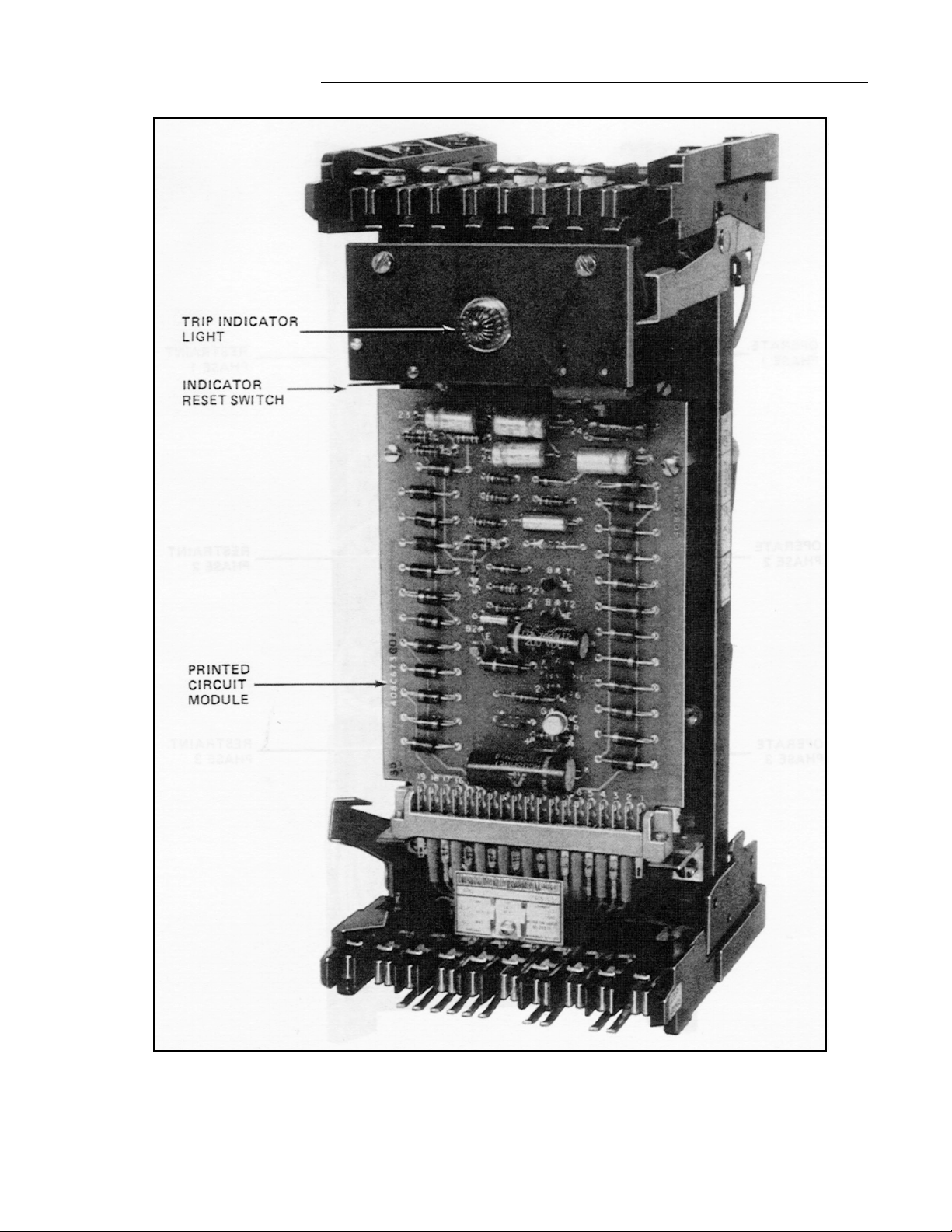
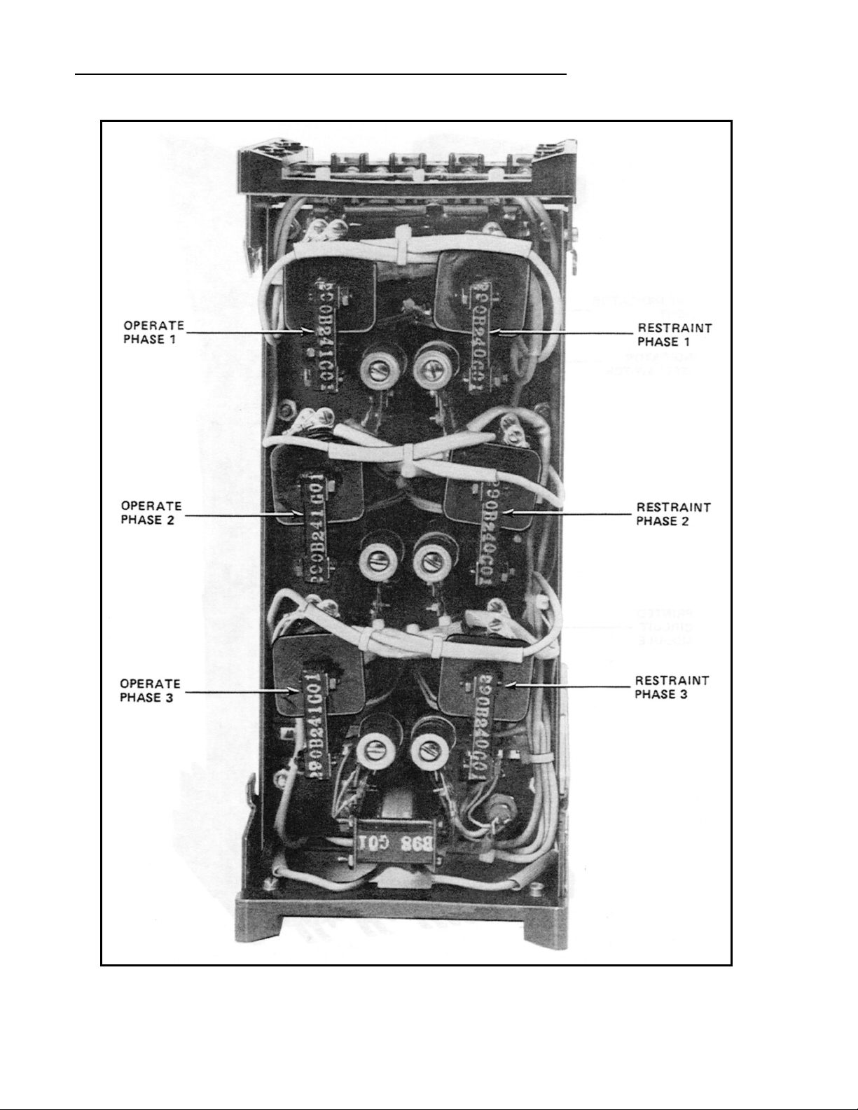
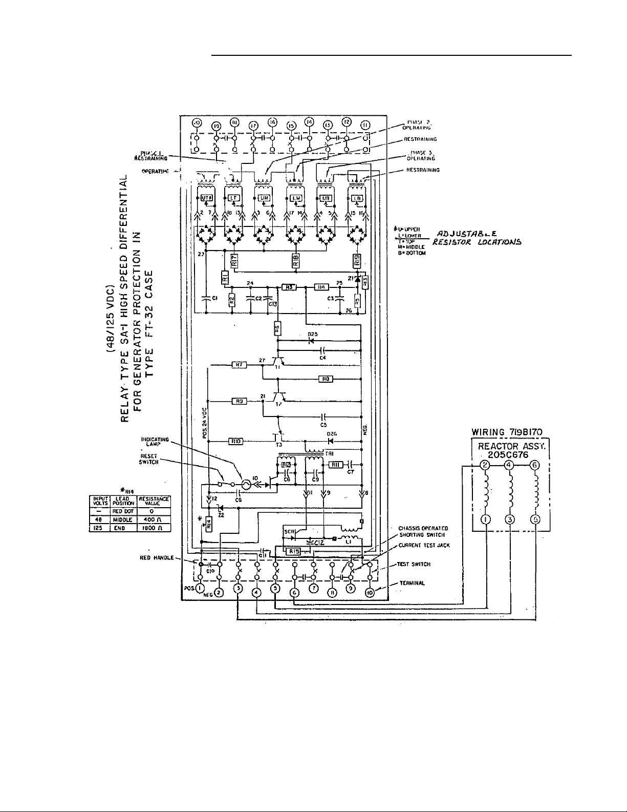
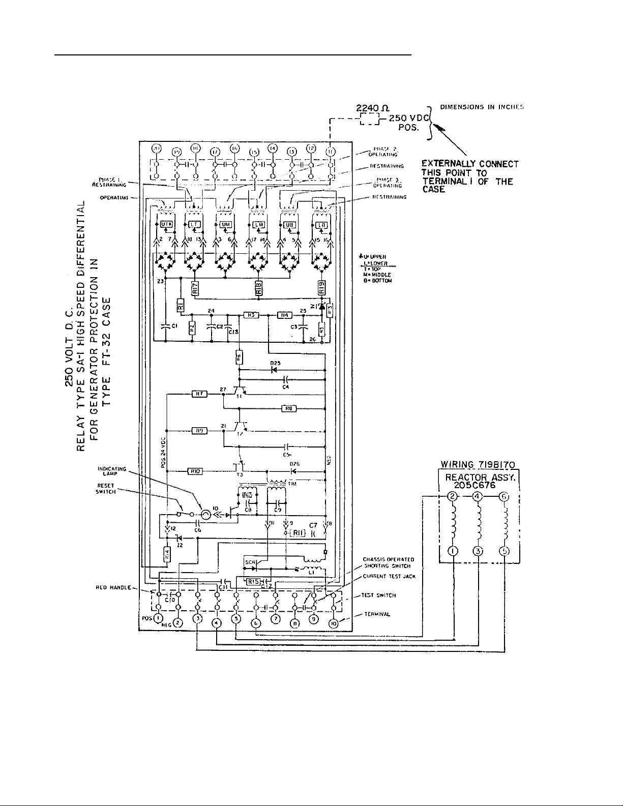
relay and their location are shown in Figures 1
through 8.
= 400/600 = 0.67. If this ct has a C200
P
= 200, and the burden should not exceed:
CL
NPV
------------------- -
133
BF
CL
1000
---------------------
NPV
0.67 200×
--------------------------- - 1.0 ohm==
133
= 0.5 ohms, the
B
R
B
1000 0.5×
--------------------------- - 3.8== =
0.67 200×
CL
All possible contingencies which may arise during installation, operation or maintenance, and all details and
variations of this equipment do not purport to be covered by these instructions. If further information is desired
by purchaser regarding this particular installation, operation or maintenance of this equipment, the local ABB
Power T&D Company Inc. representative should be contacted.
Page 2

41-348.1H
Type SA-1
Generator Differential Relay
2.1. RESTRAINT CIRCUIT
The restraint circuit of each phase consists of a center-tapped transformer, a resistor, and a full wave
rectifier bridge. The outputs of all the rectifiers are
connected in parallel. The parallel connection of rectifiers is a maximum voltage network. Hence, the
voltage applied to the filter circuit is proportional to
the phase current with the largest magnitude.
2.2. OPERATING CIRCUIT
The operating circuit consists of a transformer, a
resistor, and a full wave rectifier bridge. The outputs
of all the rectifiers are connected in parallel. This parallel connection of rectifiers is a maximum voltage
network. Hence, the voltage applied to the filter circuit is proportional to the phase current with the largest magnitude.
2.3. SENSING CIRCUIT
The sensing circuit is connected to the output of the
restraint filter circuit, the operating filter circuit and
the input to the amplifier circuit.
With no gate current flowing, the thyristor acts as an
open circuit to the breaker trip coil. When a gate current is applied tot he thyristor the thyristor connects
the breaker trip coil to the dc supply.
2.6. INDICATING CIRCUIT
The indicating circuit is triggered by a signal from the
amplifier of the relay. Under normal or non-fault conditions, the indicating circuit is turned off. When a
fault is applied to the relay, the amplifier will conduct
to cause a signal to flow into the indicator circuit.
When the indicator circuit is triggered, the lamp will
turn on. This lamp will remain lit until the indicator circuit is interrupted by resetting the micro-switch.
2.7. SURGE PROTECTION CIRCUIT
The surge protection circuit consists of two capacitors (C10 and C11) and a R-C network which is connected across the anode and cathode of the tripping
thyristor to prevent the SCR from firing by a surge of
voltage.
2.8. EXTERNAL REACTORS
2.4. AMPLIFIER CIRCUIT
The amplifier circuit consists of a two-transistor
amplifier which controls the operation of a relaxation
oscillator.
The amplifier circuit is connected to the sensing circuit such that it receives the difference in output of
the restraint filter and the operating filter. Thus, the
polarity of the input voltage to the amplifier depends
upon the relative magnitude of the voltages appearing on the restraint and operating filters. When the
voltage output of the operating filter is greater than
the output voltage of the restraint filter, a voltage of a
certain polarity appears across the input of the amplifier. To trigger the amplifier requires that the output
voltage of the operating filter be greater than the output voltage of the restraint filter.
2.5. TRIP CIRCUIT
The trip circuit consists of a thyristor which has an
anode, cathode, and a gate. The anode of the thyristor is connected to the positive side of the dc supply
and the cathode of the thyristor is connected to the
negative side of the dc supply through the trip coil of
a breaker. The gate of the thyristor is connected to
the output of the amplifier circuit through a pulse
transformer.
Three reactors are mounted on a metal plate with a
separate terminal strip. The reactors are of the saturable type.
3. OPERATION
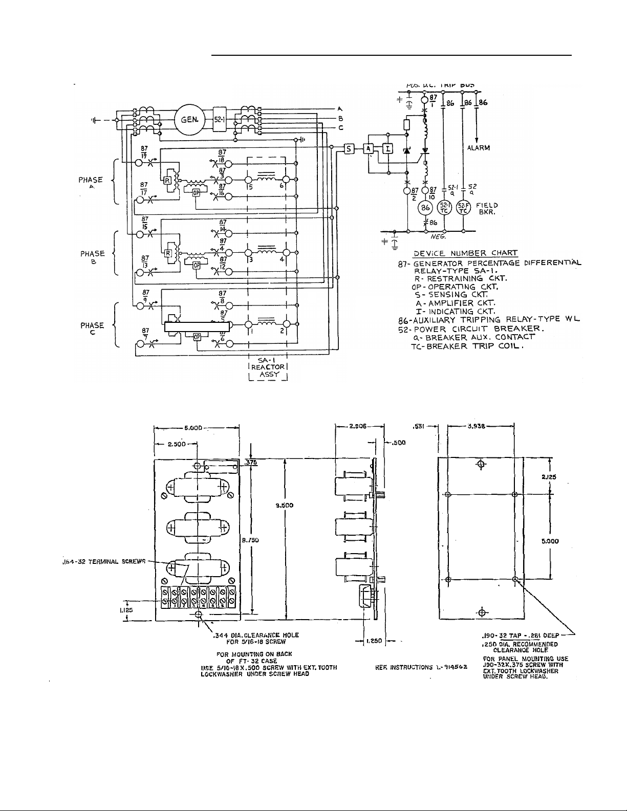
The Type SA-1 relay is connected to the protected
apparatus as shown in Figure 9. On external faults,
current flows through the primary winding of the
restraint transformers to induce a voltage on the
restraint side of the sensing circuit. If the two sets of
main current transformers have different performances, some current will flow out of the mid-tap of
the restraint transformers to the operating transformers. This will produce a voltage on the operating side
of the sensing circuit. With the relay correctly applied,
sufficient restraint voltages will exist to prevent the
operating voltage from triggering the amplifier.
The percentage slope characteristic of the relay limits the operating voltage on heavy external faults
where the performance of the two sets of current
transformers may be quite different.
On internal faults, the operating coil current is the
sum of the current flowing in each of the windings of
the restraint transformer and sufficient operating voltage is available to overcome the restraint voltage.
2
Page 3
Type SA-1
Generator Differential Relay
41-348.1H
4. CHARACTERISTICS
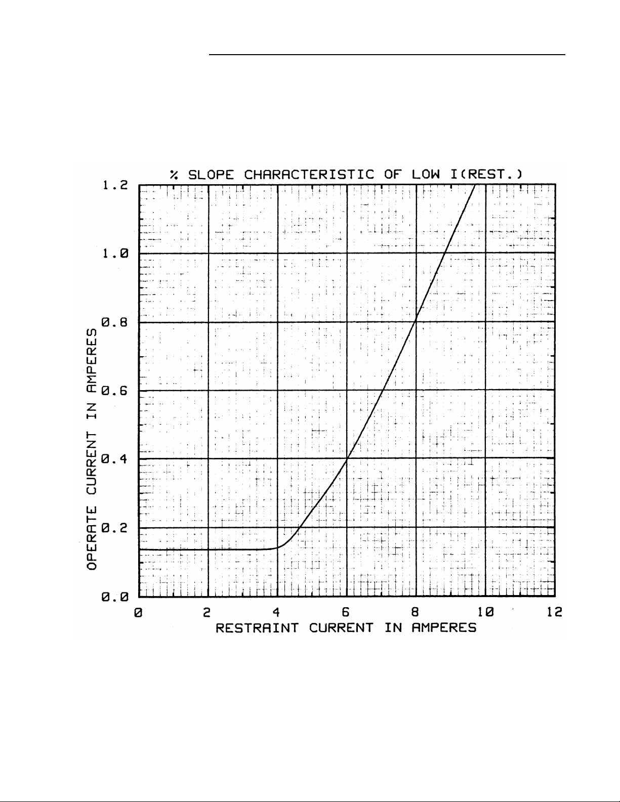
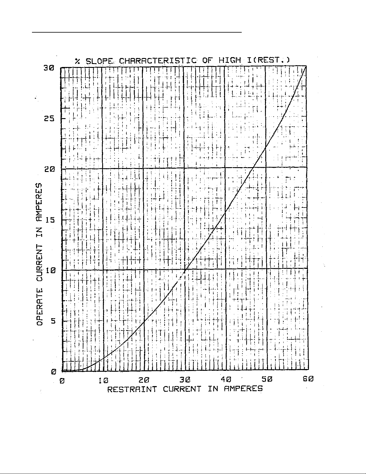
The percentage slope curves are shown in Figures
12 and 13. It will be observed that the relay operates
at 5% unbalance at 5 amperes restraint (Figure 12)
to provide high sensitivity for internal faults up to full
load conditions. At 60 amperes restraint, the operating current required to trip the relay is 30 amperes or
50% unbalance (Figure 13). Thus, when 60
amperes through-fault current is flowing, the output
of the main current transformers may vary considerably without causing incorrect operation.
The minimum pickup of the relay is 0.14 ampere or
0.5 ampere for the desensitized version.
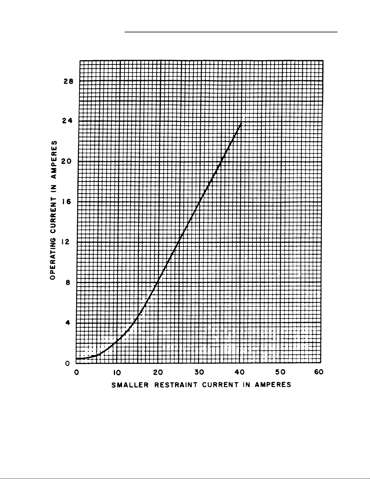
The operating characteristic of the desensitized SA1 is shown in Figure 14.
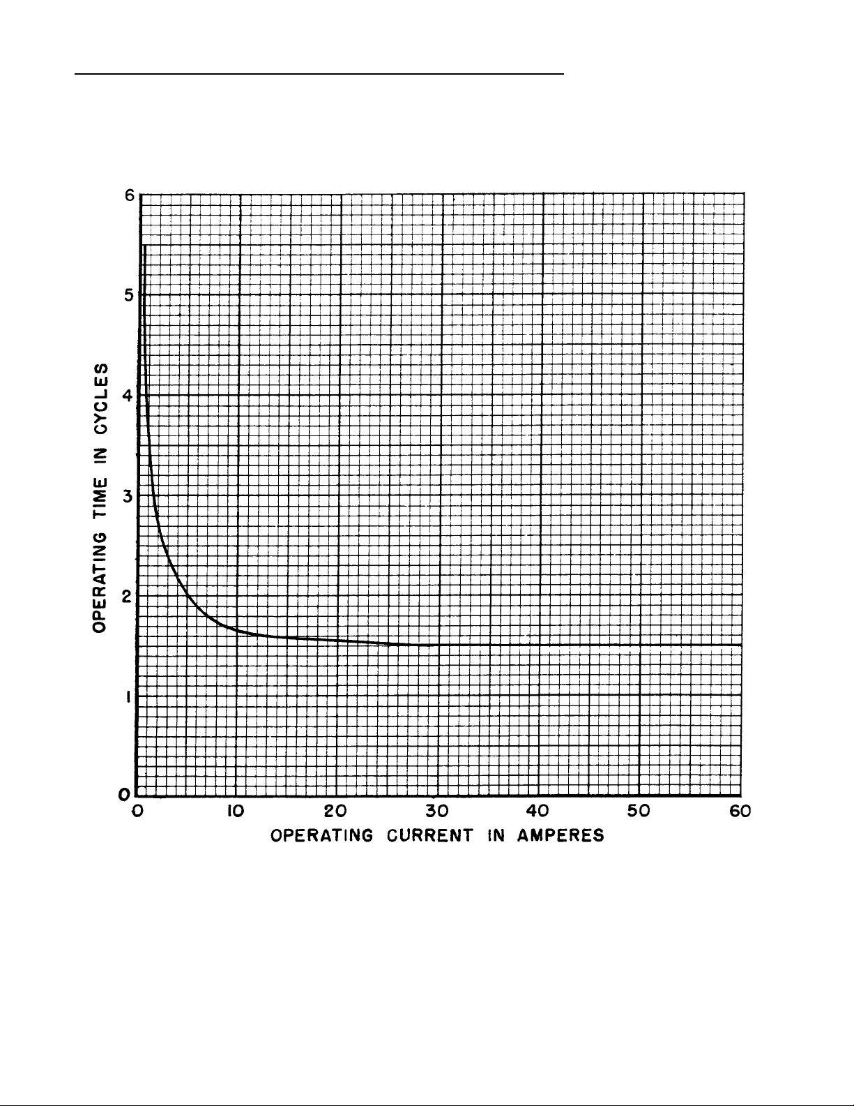
The time curve of the relay is shown in Figure 15.
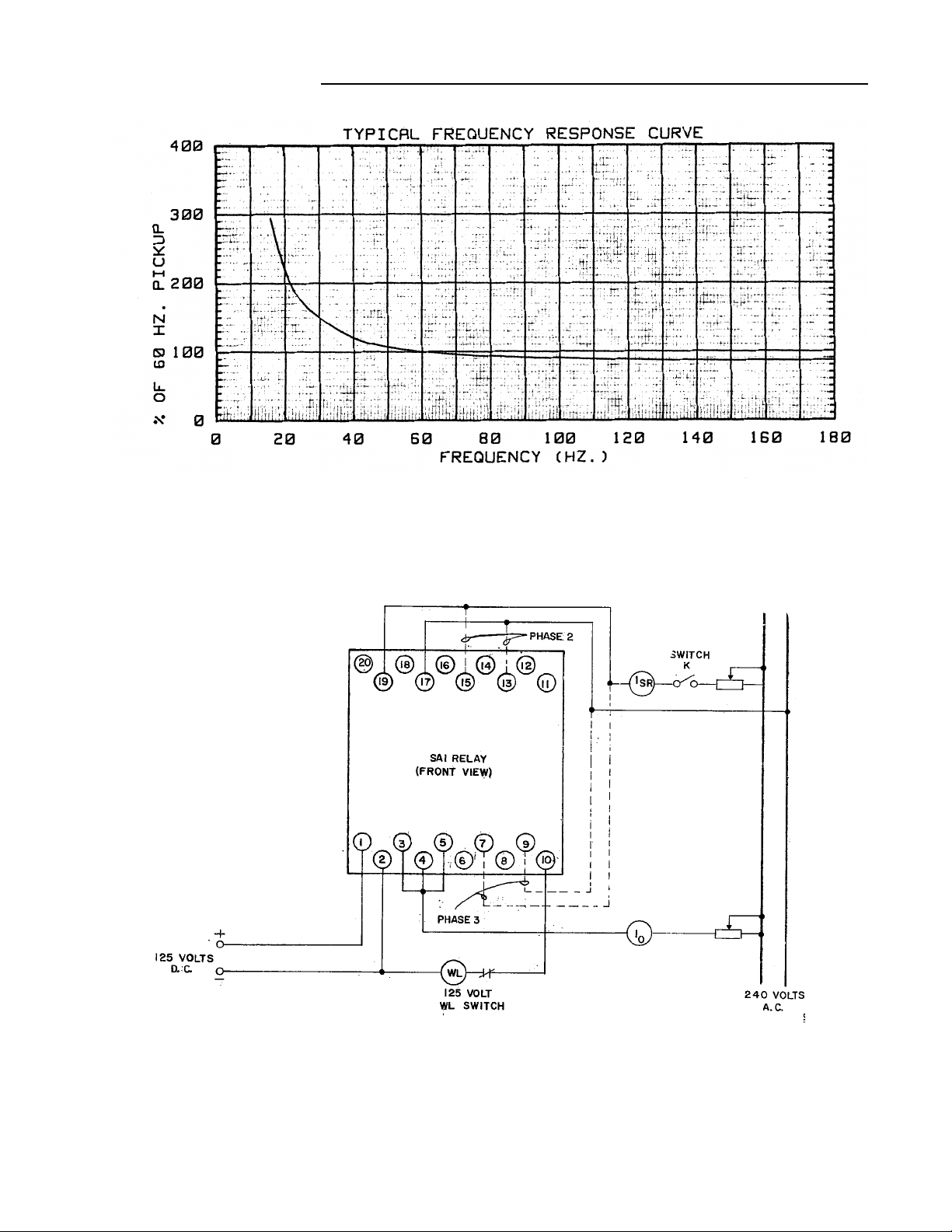
The frequency response characteristic of the SA-1
relay is shown in Figure 16.
6. SETTINGS
There are no taps on either transformer and, consequently, there are no settings to be made except for
the choice of battery voltage level.
The 48/125 Vdc relays are normally shipped for 125
volts. For 48 Vdc applications use the mid-tap on the
resistor mounted at the top of the relay. The red dot
on the resistor is the common point – DO NOT
REMOVE.
7. INSTALLATION
The relay should be mounted on switchboard panels
or their equivalent in a location free from moisture.
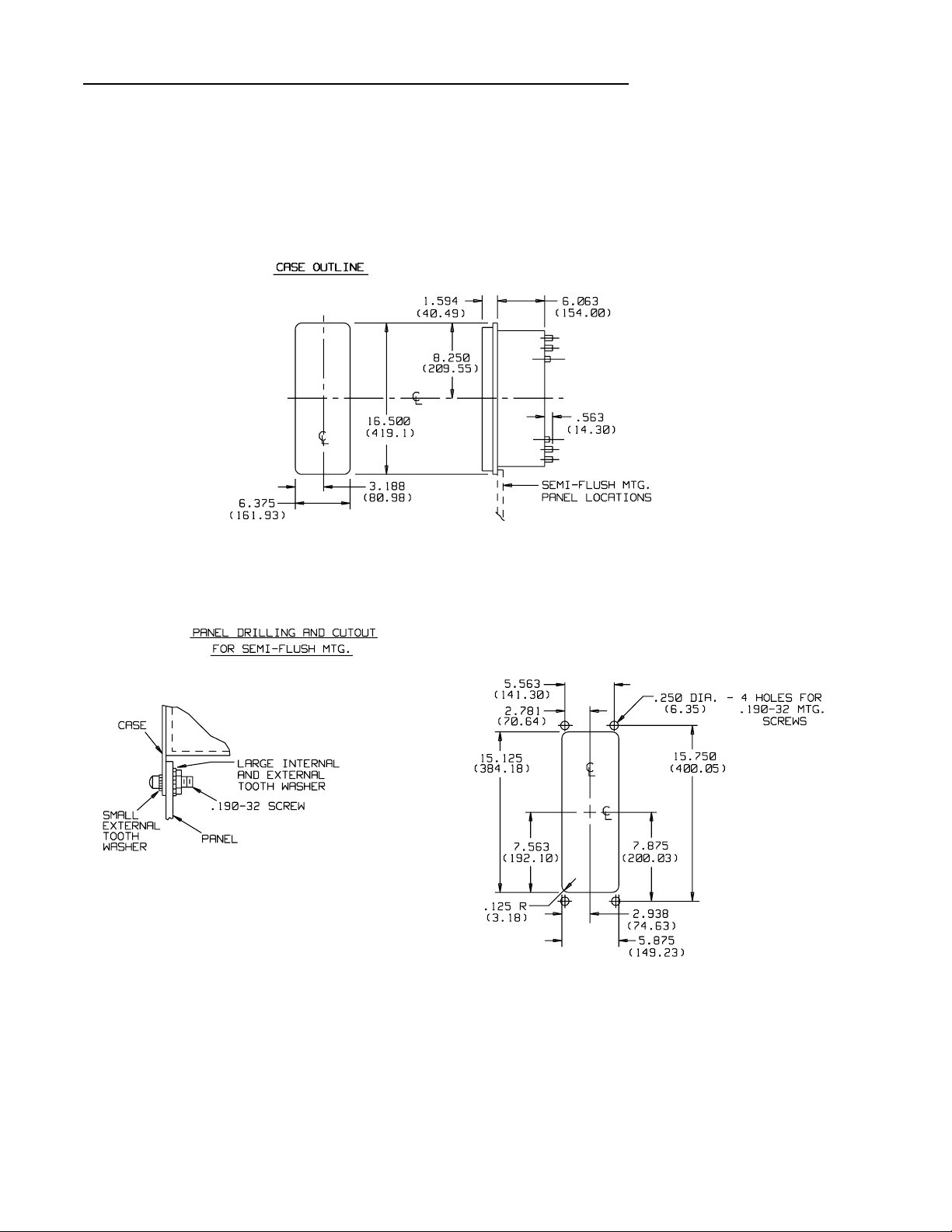
Mount the relay vertically by means of the four
mounting holes on the flange for semi-flush mounting.
Either a mounting stud or the mounting screws may
be utilized for grounding the relay. The electrical
connections may be made directly to the terminals
by means of screws.
5. ENERGY REQUIREMENTS
Each Restraint Circuit
Burden at 5 amperes is 0.25 VA
Continuous rating 20 amperes
1 second rating 300 amperes
Operating Circuit
The burden imposed by the operating circuit on
each circuit transformer is variable because of the
saturating transformer and reactors. At 0.5 amperes,
it is 0.37 VA, and at 60 amperes it is 170 VA.
Continuous rating 10 amperes
1 second rating 200 amperes
Amplifier
The dc burden on the station battery is:
Volts Milliamperes Watts
125 dc
48 dc
55
60
6.9
2.9
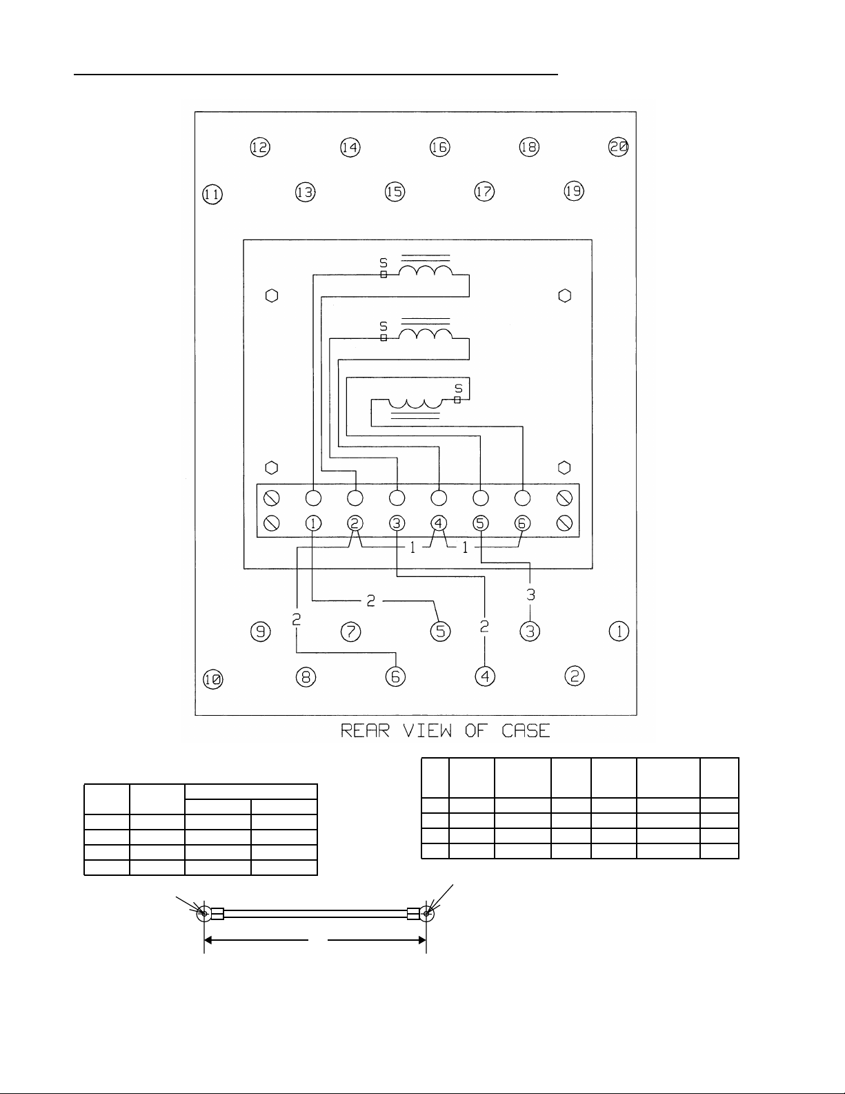
The external reactor assembly should be mounted
and wired per “interwiring Connection Drawing”, Figure 11.
For detailed FT case information, refer to I.L. 41-
076.
8. ADJUSTMENTS AND MAINTENANCE
The proper adjustments to insure correct operation
of this relay have been made at the factory and
should not be disturbed after receipt by the customer.
8.1. ROUTINE TEST
The following check is recommended to insure that
the relay is in proper working order. All checks can
best be performed by connecting the relay per the
test circuit of Figure 17. Due to high impedance of the
external reactor, prior to saturation, the test circuit of
Figure 17 should be used to test the relay only. The
reactors can be checked by applying 0.2 amperes 60
hertz and reading the voltage drop across the reactor
with a high impedance True RMS reading voltmeter.
The voltage drop will be between 20 and 26 volts
True RMS. For 0.4 amperes input, the reading
should be between 29 and 31 volts True RMS.
3
Page 4

41-348.1H
Type SA-1
Generator Differential Relay
1. Minimum Trip Current with IR set at zero
amperes, apply 0.14 ±5% (0.5 ±5% got desensi-
tized SA-1) amperes operating current to each
operating circuit of the relay. The relay should
operate and the indicator lamp should light.
2. Differential Characteristic
a) Apply IR of 5 amperes and adjust the operat-
ing current until the relay operates. The relay
should operate and the indicator lamp should
light with an operating current of 0.25 ±5%
amperes (0.71 5% for desensitized SA-1).
Repeat for each phase of the relay.
b) Apply IR of 60 amperes and adjust the oper-
ating current until the relay operates. The
relay should operate and the indicator lamp
should light with an operating current of
30 ±10% amperes. Repeat for each phase of
the relay. (IR = 40 amperes and IO =
24 ±10% for desensitized SA-1).
8.2. MAINTENANCE
All relays should be checked once a year to detect
any failures which may have occurred. The tantalum
capacitors C1, C2, C3, C4 and C13 may have a common mode failure characteristic and should be
checked visually for symptoms of electrolyte leakage
every year and replaced if necessary.
8.3. CALIBRATION
Use the following procedure for calibrating the relay if
the relay adjustments have been disturbed. This procedure should not be used until it is apparent the
relay is not in proper working order.
1. Minimum Trip Current – Connect the relay per
test circuit of Figure 17 with switch K open.
Adjust the operating resistor in the rear of the
relay until the relay operates with IO equal to
0.14 ampere, 0.5 ampere for desensitized SA-1.
DO NOT make adjustments to the resistor
unless the dc is disconnected.
The indicator lamp should light when the relay
operates.
Repeat for each phase of the relay.
2. Percentage Slope Characteristic (Low Cur-
rent). Close switch K and set IR equal to 5
amperes and adjust the restraint resistor in the
rear of the relay until the relay operates with Io =
0.25 ±.010 amperes. DO NOT adjust resistor
with dc applied to relay.
The indicator lamp should light when the relay
operates.
Repeat for each phase of the relay.
Percentage Slope Characteristic (High Current) – Set IR equal to 60 amperes for the oper-
ating current of 30 amperes. Replace the resistor
R17 if necessary. The value of R17 can be
between 0 and 100 ohms. Repeat for the other
two phases if necessary, replacing R18 and R19
respectively.
3. Electrical Checkpoints – See Table 1.
9. RENEWAL PARTS
Repair work can be done most satisfactorily at the
factory. However, interchangeable parts can be furnished to customers who are equipped for doing
repair work. When ordering parts, always give the
nameplate data.
10.ELECTRICAL CHECKPOINTS
Connect relay per test circuit of Figure 17. All voltage
readings should be made with a high resistance voltmeter. Refer to component location of checkpoints.
Voltage readings are approximate. The voltage readings “Input to Amplifier” should not be taken with
relay in service.
4
Page 5
Type SA-1
Generator Differential Relay
41-348.1H
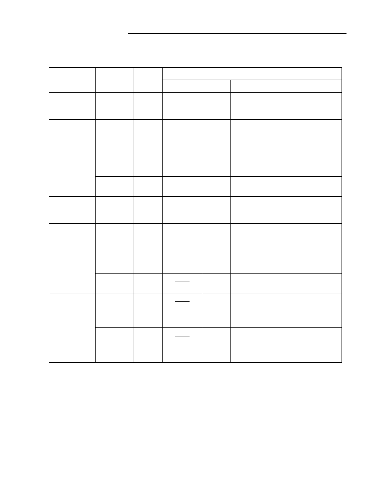
Table 1:
(Values in Parenthesis Represent Desensitized SA-1)
CIRCUIT
Operating
Sensing
(Operating)
Restraint
Sensing
(Restraint)
PRIMARY
CURRENT PHASE
0.14A
(0.5A)
1
2
3
Any
0.14A
phase
(0.5)
Any
30.0A
phase
5.0A 1
2
3
Any
5.0A
phase
CHECKPOINTS (Typical Value)
TERMINAL VALUE FUNCTION
2 - 7
3 - 6
4 - 5
2.5 ac
2.5 ac
2.5 ac
Input to operate rectifier
Input to operate rectifier
Input to operate rectifier
+ to 23 - 26
24 - 26
24 - 8
8 - 25
25 - 26
2.1 dc
1.85 dc
0.55 dc
0.65 dc
0.65 dc
Output to rectifier
a. Output to operating sensing circuit
b. Input to amplifier
c.
d. Output to restraint sensing circuit
Ref.: a = b + c + d
+ to 24 - 26 51.0 dc
18 - 13
17 - 14
15 - 16
6.0 ac
6.0 ac
6.0 ac
Input to restraint rectifier
Input to restraint rectifier
Input to restraint rectifier
+ to 25 - 26
25 - 8
8 - 24
24 - 26
2.1 dc
1.2 dc
0.6 dc
0.3 dc
a. Output of restraint sensing circuit
b.
c. Input to amplifier
d. Output to operating sensing circuit
Ref.: a = b + c + d
Amplifier
60.0A
0
Minimum
Trip
Current
+5%
Any
phase
Any
phase
+ to 25 - 26 42.0 dc
+ to -
27 - 8
12 - 8
10 - 8
0.7 dc
24.0 dc
24.0 dc
+ to -
27 - 8
12 - 8
21 - 8
0.5 dc
24.0 dc
10.0 dc
5
Page 6
41-348.1H
Type SA-1
Generator Differential Relay
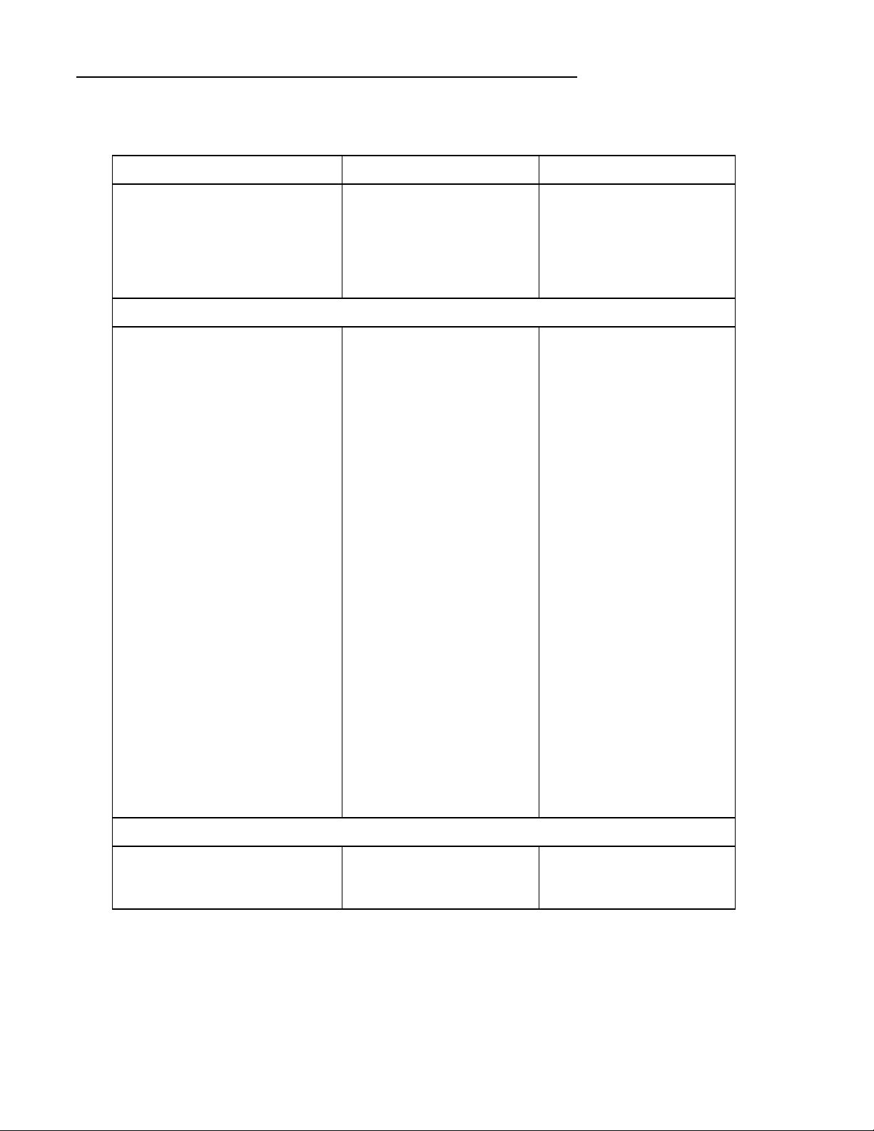
Table 2:
Electrical Part List
Circuit Symbol Reference Style
Resistors
Resistors
Resistors
Zener
SCR
Reactor
Resistor
Resistor
Resistor
Resistor
Resistor
Resistor
Resistor
Resistor
Resistor
Resistor
Resistor
Resistor
Capacitor
Capacitor
Capacitor
Capacitor
Capacitor
Capacitor
UT, UM, UB
LT, LM, LB
R14
Z2
60 Ohms, 25W
265 Ohms, 25W
1.8K, 40 W
IN2986B
1875676
1725542
187A321H06
629A798H03
184A614H05
L1
1478B98G01
SA Module Style Number 408C673G01 Sub 35
R1
R2
R3, R4 R5
R6
R7
R8
R9
R10
R11
R12
R13
†
R17, R18, R19
C1, C2, C3, C13
C4
C5
C6
C7
C8, C9
270 Ohms, 1W
2K, 5%
15K, 5%
2.7K, 5%
68K, 5%
27K, 5%
2.2K, 5%
100 Ohms, 10%
220 Ohms, 5%
680 Ohms, 5%
47K, 5%
33 Ohms, 5%
25 MFD, 125V
22 MFD, 35V
0.5 MFD, 200V
2.2 MFD, 35V
2.0 MFD, 200V
0.47 MFD, 50V
184A635H06
184A763H34
184A763H55
184A763H37
184A763H71
184A763H61
184A763H35
184A763H03
184A763H11
184A763H23
184A763H67
187A290H13
184A637H01
184A661H16
187A624H03
837A241H16
187A624H05
762A680H04
Diode
Diode
Zener
SCR
Transistor
Transistor
Transformer
D1 to D24
D25, D26
Z1
T1, T2
T3
TR-1
IN4821
IN645A
IN752A
K1149-13
2N3417
2N2647
188A342H16
837A692H04
186A797H12
184A640H13
848A851H02
629A435H01
629A372H02
SPK Module Style Number 1584C21G01
Resistor
Capacitor
Capacitor
†
NOTE: The values of R17, R18 and R19 are between 0 and 100 Ohms. They are determined in test.
R15
C10, C11
C12
470 Ohms, 1W
0.01 MFD, 1.5KV
2.0 MFD, 200V
187A643H19
3516A36H03
3509A33H01
6
Page 7
Type SA-1
Generator Differential Relay
41-348.1H
Figure 1. Type SA-1 Generator Differential Relay without Case (Front View)
7
Page 8
41-348.1H
Type SA-1
Generator Differential Relay
Figure 2. Type SA-1 Generator Differential Relay without Case (Rear View)
8
Page 9
Type SA-1
Generator Differential Relay
41-348.1H
Figure 3. Internal Schematic of Type SA-1 Relay 48/125 Vdc
629A406
Sub 15
9
Page 10
41-348.1H
Type SA-1
Generator Differential Relay
10
876A613
Sub 9
Figure 4. Internal Schematic of Type SA-1 Relay 250 Vdc
Page 11
Type SA-1
Generator Differential Relay
41-348.1H
(DESENSITIZED)
TYPE FT-32 CASE
FOR GENERATOR PROTECTION IN
RELAY TYPE SA-1 HIGH SPEED DIFFERENTIAL
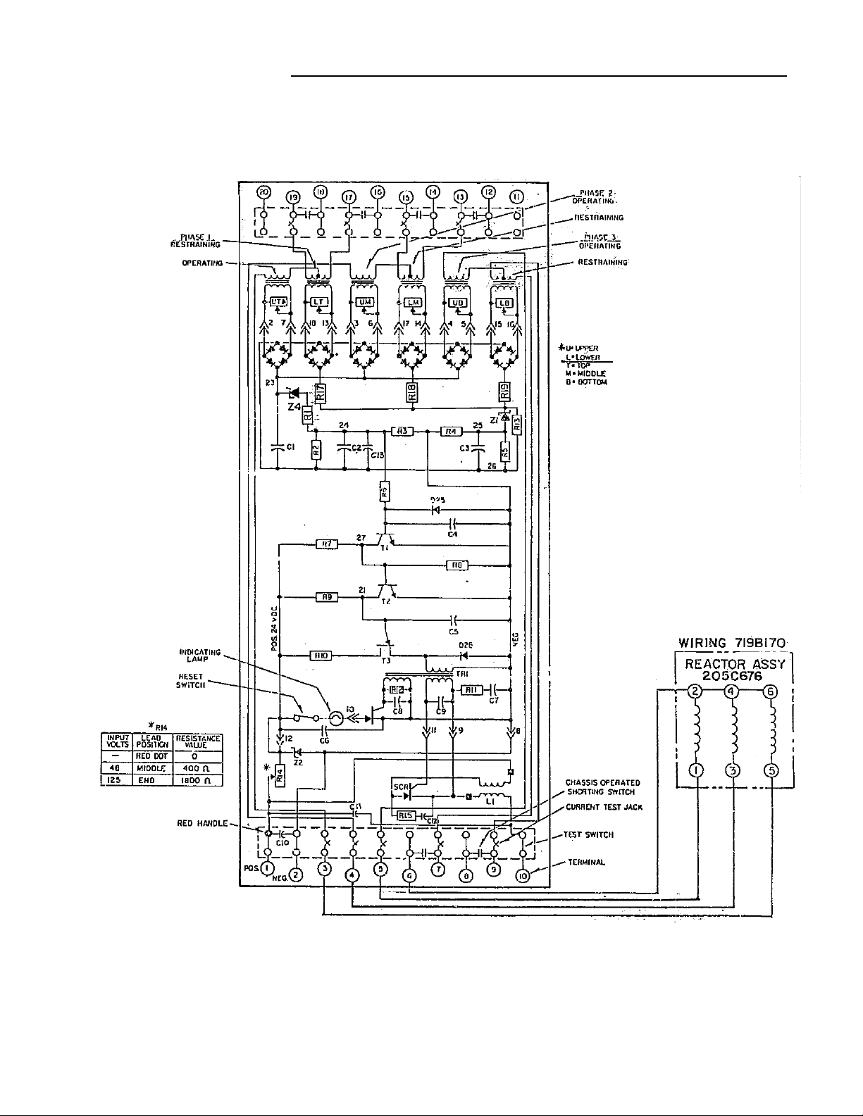
Figure 5. Internal Schematic of Desensitized SA-1 Relay
877A847
Sub 8
11
Page 12
41-348.1H
23
R17
Type SA-1
Generator Differential Relay
+
C1
12
762A601
Sub 9
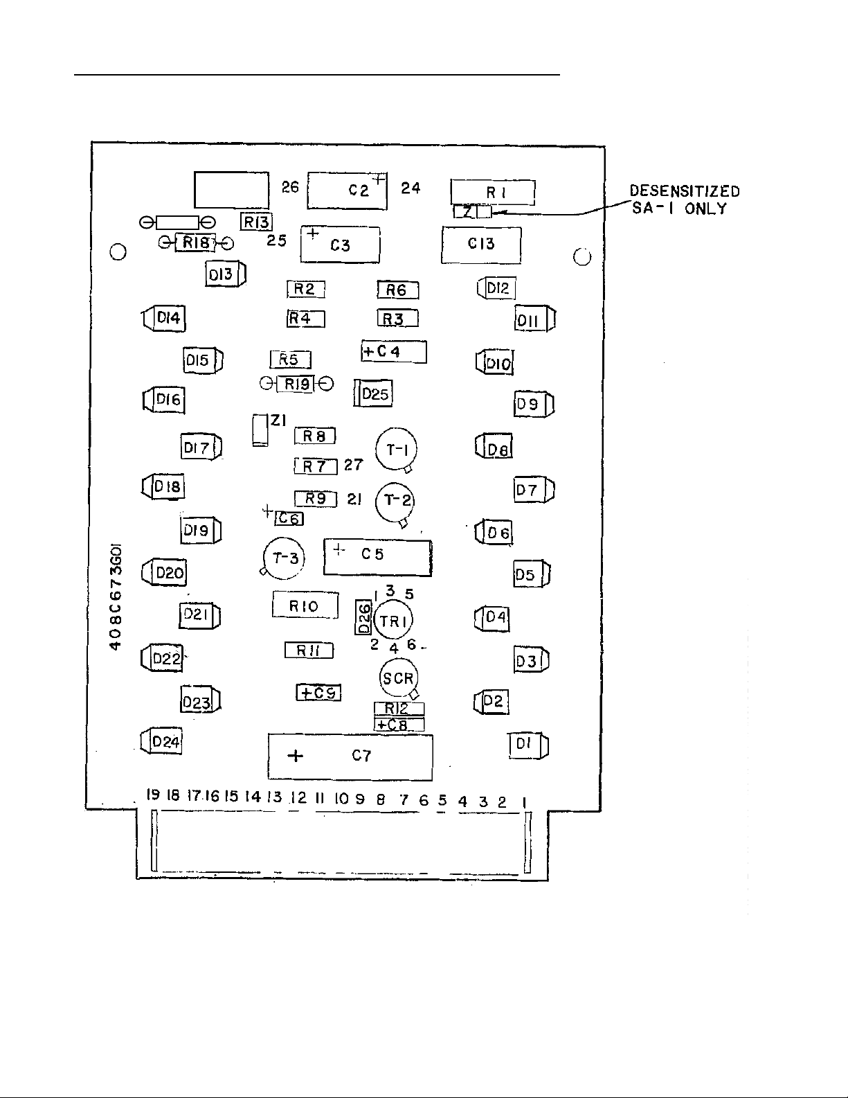
Figure 6. Component Location for 48/125 Vdc
Page 13
Type SA-1
Generator Differential Relay
41-348.1H
*
Denotes Change
867A639
* Sub 5
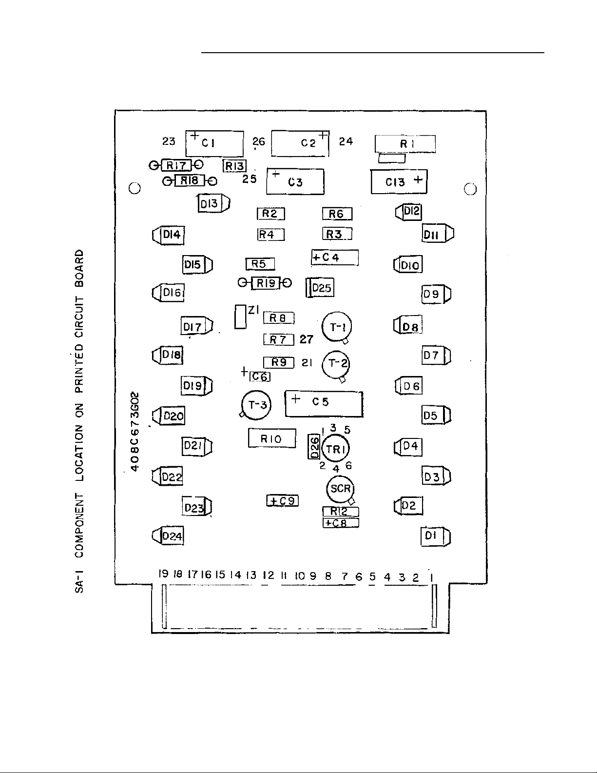
Figure 7. Component Location for 250 Vdc
13
Page 14
41-348.1H
Type SA-1
Generator Differential Relay
COMPONENT LOCATION
COMPONENT LOCATION
48/125 V
48/125 V
2
2
5
C
C
C
C
1
1
1
1
1
1
3
3
1
1
0
0
C11 & C10 .01 uf 3516A36H03
C11 & C10 .01 uf 3516A36H03
C12 2.0 uf 3509A33H01
C12 2.0 uf 3509A33H01
R15 470 Ohm 187A643H19
R15 470 Ohm 187A643H19
5
4
4
R15
R15
C12
C12
SPK 1584C01G01
SPK 1584C01G01
COMPONENT LOCATION
250 V
2
C
C
1
1
1
3
1
0
5
4
R15
6 7
SPK 1584C01G02
C11 & C10 .01 uf 3516A36H03
R15 470 Ohm 187A643H19
Illustration
3532A07
Sub 2
14
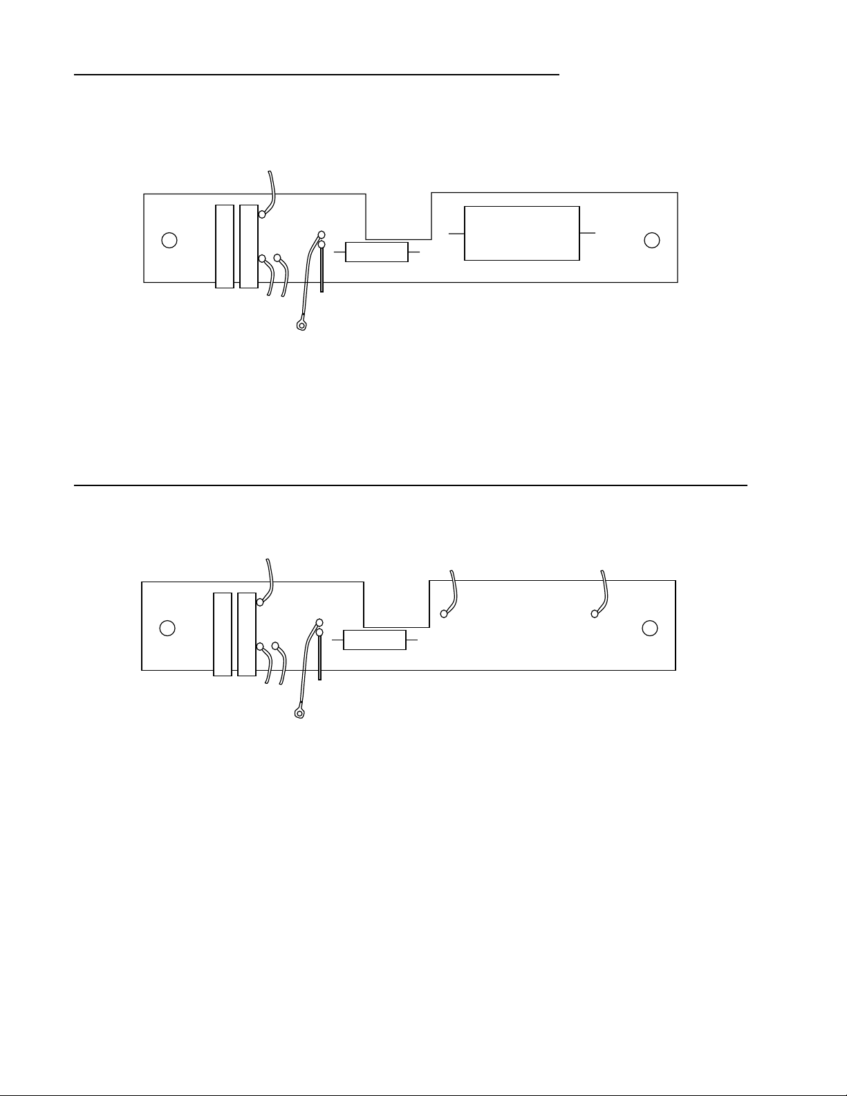
Figure 8. Component Location of the SPK Module
Page 15
Type SA-1
Generator Differential Relay
41-348.1H
Figure 9. External Schematic of Type SA-1 Relay for Generator Protection
775B965
*Sub 4
Figure 10. Reactor Outline
775B982
Sub 1
15
Page 16
41-348.1H
Type SA-1
Generator Differential Relay
NOTE: A - PLACE IT. 1 TO 3 IN IT. 5 FOR SHIPPING
Lead
IT.
1 3.00 .164 - 32 .164 - 32
2 4.00 .164 - 32 .190 - 32
3 3.00 .164 - 32 .190 - 32
4 13.438 .164 - 32 .190 - 32
L
A
SCREW SIZE
AB
Figure 11. Relay and Reactor Interconnection
*
Denotes Change
16
±.156
L
PART
ITEM
NAME
01 LEAD 57Z0301 616 A 63-D-653 2
02 LEAD 57Z0401 622 A 63-D-655 3
03 LEAD 57Z0301 622 A 63-D-655 1
05 BAG 836A618 H04 B 27-D-5478 1
B
STYLE
DWG.
ITEM
GR.
NOTE
CODE
ENG.
REF. REQ
775B981
* Sub 5
Page 17
Type SA-1
Generator Differential Relay
41-348.1H
Figure 12. Percentage Slope characteristic at Low Value of Restraint Current
3537A44
Sub 2
17
Page 18
41-348.1H
Type SA-1
Generator Differential Relay
18
878A742
Sub 3
Figure 13. Percentage Slope Characteristic at High Value of Restraint Current
Page 19
Type SA-1
Generator Differential Relay
41-348.1H
Figure 14. Percentage Slope Characteristic of High Value Restraint Current for Desensitized SA-1 Relay
619406
Sub 1
19
Page 20
41-348.1H
Type SA-1
Generator Differential Relay
20
477706
Sub 1
Figure 15. Typical Operation Time Characteristic
Page 21
Type SA-1
Generator Differential Relay
41-348.1H
3537A45
Sub 2
Figure 16. Typical Frequency Response Curve
Figure 17. Typical Frequency Response Curve
184A864
Sub 4
21
Page 22
41-348.1H
Type SA-1
Generator Differential Relay
*
Denotes Change
22
3519A69
* Sub 4
Figure 18. Outline and Drilling Plan for the Type SA-1 Relay in Type FT-32 Case
Page 23

Type SA-1
Generator Differential Relay
41-348.1H
NOTES
23
Page 24

41-348.1H
Type SA-1
Generator Differential Relay
ABB Automation, Inc.
Substation Automation & Protection Division
4300 Coral Ridge Drive
Coral Springs, FL 33065
954 752-6700
800 523-2620
24
❖
www.abb.com/papd
ABB Automation, Inc.
Substation Automation & Protection Division
7036 Snowdrift Road, Suite 2
Allentown, PA 18106
610 395-7333
800 634-6005
 Loading...