


 Loading...
—
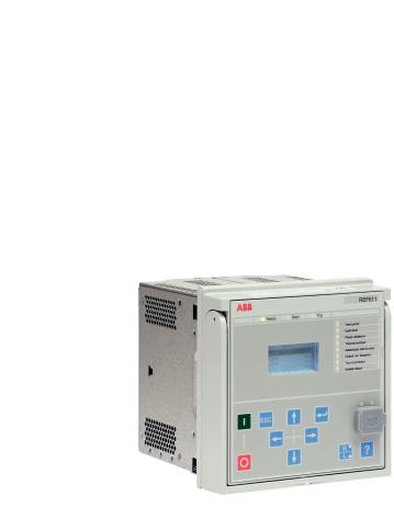
RELION® PROTECTION AND CONTROL
611 series
Operation Manual
Document ID: 1MRS757453
Issued: 2019-04-10
Revision: C
Product version: 2.0
© Copyright 2019 ABB. All rights reserved
Copyright
This document and parts thereof must not be reproduced or copied without written permission from ABB, and the contents thereof must not be imparted to a third party, nor used for any unauthorized purpose.
The software or hardware described in this document is furnished under a license and may be used, copied, or disclosed only in accordance with the terms of such license.
Trademarks
ABB and Relion are registered trademarks of the ABB Group. All other brand or product names mentioned in this document may be trademarks or registered trademarks of their respective holders.
Warranty
Please inquire about the terms of warranty from your nearest ABB representative.
www.abb.com/relion
Disclaimer
The data, examples and diagrams in this manual are included solely for the concept or product description and are not to be deemed as a statement of guaranteed properties. All persons responsible for applying the equipment addressed in this manual must satisfy themselves that each intended application is suitable and acceptable, including that any applicable safety or other operational requirements are complied with. In particular, any risks in applications where a system failure and/or product failure would create a risk for harm to property or persons (including but not limited to personal injuries or death) shall be the sole responsibility of the person or entity applying the equipment, and those so responsible are hereby requested to ensure that all measures are taken to exclude or mitigate such risks.
This product has been designed to be connected and communicate data and information via a network interface which should be connected to a secure network. It is the sole responsibility of the person or entity responsible for network administration to ensure a secure connection to the network and to take the necessary measures (such as, but not limited to, installation of firewalls, application of authentication measures, encryption of data, installation of anti virus programs, etc.) to protect the product and the network, its system and interface included, against any kind of security breaches, unauthorized access, interference, intrusion, leakage and/or theft of data or information. ABB is not liable for any such damages and/or losses.
This document has been carefully checked by ABB but deviations cannot be completely ruled out. In case any errors are detected, the reader is kindly requested to notify the manufacturer. Other than under explicit contractual commitments, in no event shall ABB be responsible or liable for any loss or damage resulting from the use of this manual or the application of the equipment.
Conformity
This product complies with the directive of the Council of the European Communities on the approximation of the laws of the Member States relating to electromagnetic compatibility (EMC Directive 2014/30/EU) and concerning electrical equipment for use within specified voltage limits (Low-voltage directive 2014/35/EU). This conformity is the result of tests conducted by ABB in accordance with the product standard EN 60255-26 for the EMC directive, and with the product standards EN 60255-1 and EN 60255-27 for the low voltage directive. The product is designed in accordance with the international standards of the IEC 60255 series.

Safety information
Dangerous voltages can occur on the connectors, even though the auxiliary voltage has been disconnected.
Non-observance can result in death, personal injury or substantial property damage.
Only a competent electrician is allowed to carry out the electrical installation.
National and local electrical safety regulations must always be followed.
The frame of the protection relay has to be carefully earthed.
When the plug-in unit has been detached from the case, do not touch the inside of the case. The relay case internals may contain high voltage potential and touching these may cause personal injury.
The protection relay contains components which are sensitive to electrostatic discharge. Unnecessary touching of electronic components must therefore be avoided.
Whenever changes are made in the protection relay, measures should be taken to avoid inadvertent tripping.

Table of contents
Table of contents |
|
|
Section 1 |
Introduction....................................................................... |
7 |
|
This manual........................................................................................ |
7 |
|
Intended audience.............................................................................. |
7 |
|
Product documentation....................................................................... |
8 |
|
Product documentation set............................................................ |
8 |
|
Document revision history............................................................. |
8 |
|
Related documentation.................................................................. |
9 |
|
Symbols and conventions................................................................... |
9 |
|
Symbols......................................................................................... |
9 |
|
Document conventions.................................................................. |
9 |
|
Functions, codes and symbols.................................................... |
10 |
Section 2 |
Environmental aspects................................................... |
15 |
|
Sustainable development................................................................. |
15 |
|
Disposal of a protection relay........................................................... |
15 |
Section 3 611 series overview........................................................ |
17 |
|
|
Overview........................................................................................... |
17 |
|
Local HMI......................................................................................... |
17 |
|
Display......................................................................................... |
18 |
|
LEDs............................................................................................ |
19 |
|
Keypad........................................................................................ |
20 |
|
Local HMI functionality................................................................ |
22 |
|
Protection and alarm indication.............................................. |
22 |
|
Parameter management ........................................................ |
23 |
|
Front communication.............................................................. |
24 |
|
Web HMI........................................................................................... |
24 |
|
Command buttons....................................................................... |
26 |
|
Authorization..................................................................................... |
27 |
|
Audit trail...................................................................................... |
28 |
|
Communication................................................................................. |
30 |
|
Self-healing Ethernet ring............................................................ |
30 |
|
Ethernet redundancy................................................................... |
31 |
|
Secure communication................................................................ |
33 |
|
PCM600 tool..................................................................................... |
34 |
|
Connectivity packages................................................................. |
34 |
|
PCM600 and relay connectivity package version........................ |
34 |
Section 4 Using the HMI................................................................. |
37 |
|
|
Using the local HMI.......................................................................... |
37 |
611 series |
1 |
Operation Manual |
|

Table of contents
Logging in.................................................................................... |
37 |
Logging out.................................................................................. |
38 |
Turning the display backlight on.................................................. |
38 |
Selecting local or remote use...................................................... |
39 |
Identifying the device................................................................... |
39 |
Identifying relay's IEC 61850 version..................................... |
40 |
Adjusting the display contrast...................................................... |
40 |
Changing the local HMI language............................................... |
41 |
Changing display symbols........................................................... |
41 |
Changing setting visibility............................................................ |
41 |
Navigating in the menu................................................................ |
42 |
Menu structure....................................................................... |
42 |
Scrolling the display............................................................... |
43 |
Changing the default view...................................................... |
43 |
Browsing setting values............................................................... |
43 |
Editing values.............................................................................. |
44 |
Editing numerical values........................................................ |
44 |
Editing string values............................................................... |
46 |
Editing enumerated values..................................................... |
46 |
Committing settings..................................................................... |
46 |
Clearing and acknowledging....................................................... |
47 |
Using the local HMI help.............................................................. |
48 |
Using the Web HMI.......................................................................... |
48 |
Logging in.................................................................................... |
48 |
Logging out.................................................................................. |
49 |
Identifying device......................................................................... |
49 |
Navigating in menus.................................................................... |
50 |
Menu structure....................................................................... |
51 |
Showing parameters.................................................................... |
52 |
Editing values.............................................................................. |
55 |
Committing settings..................................................................... |
58 |
Clearing and acknowledging....................................................... |
60 |
Selecting programmable LEDs view............................................ |
61 |
Selecting event view.................................................................... |
62 |
Selecting disturbance records view............................................. |
64 |
Saving disturbance records.................................................... |
64 |
Triggering disturbance recorder manually.............................. |
65 |
Deleting disturbance records.................................................. |
66 |
Selecting phasor diagrams.......................................................... |
66 |
Selecting fault records................................................................. |
69 |
Selecting signal configuration...................................................... |
71 |
Import and export of settings....................................................... |
76 |
Exporting settings .................................................................. |
76 |
2 |
611 series |
|
Operation Manual |
Table of contents
|
Importing settings .................................................................. |
77 |
|
Exporting report summary........................................................... |
79 |
|
Using Web HMI help.................................................................... |
80 |
Section 5 |
IED operation ................................................................ |
83 |
|
Normal operation.............................................................................. |
83 |
|
Disturbance identification................................................................. |
83 |
|
Disturbance recording triggering................................................. |
84 |
|
Disturbance record analysis........................................................ |
84 |
|
Disturbance reports..................................................................... |
84 |
|
Relay self-supervision................................................................. |
84 |
|
Relay parametrization....................................................................... |
85 |
|
Settings for relay functionality...................................................... |
85 |
|
Settings for different operating conditions................................... |
85 |
Section 6 |
Operating procedures..................................................... |
87 |
|
Monitoring......................................................................................... |
87 |
|
Indications................................................................................... |
87 |
|
Monitoring indication messages............................................. |
87 |
|
Monitoring an internal relay fault ........................................... |
87 |
|
Monitoring condition monitoring data..................................... |
88 |
|
Measured and calculated values................................................. |
88 |
|
Measured values.................................................................... |
88 |
|
Using the local HMI for monitoring......................................... |
89 |
|
Recorded data............................................................................. |
89 |
|
Creating disturbance recordings............................................ |
89 |
|
Monitoring disturbance recorder data..................................... |
90 |
|
Controlling and reading of disturbance recorder data............ |
90 |
|
Monitoring fault records.......................................................... |
91 |
|
Monitoring events................................................................... |
91 |
|
Remote monitoring...................................................................... |
92 |
|
Monitoring protection relays remotely.................................... |
92 |
|
Controlling........................................................................................ |
92 |
|
Controlling via the control menu.................................................. |
92 |
|
Controlling with the closing delay................................................ |
93 |
|
Resetting IED................................................................................... |
94 |
|
Clearing and acknowledging via the local HMI............................ |
94 |
|
Changing the IED functionality......................................................... |
95 |
|
Defining the setting group............................................................ |
95 |
|
Activating a setting group....................................................... |
95 |
|
Copying a setting group......................................................... |
96 |
|
Browsing and editing setting group values............................. |
96 |
|
Activating programmable LEDs................................................... |
97 |
|
Setting autoscroll delay............................................................... |
98 |
611 series |
3 |
Operation Manual |
|

Table of contents
Section 7 |
Troubleshooting ............................................................. |
99 |
|
Fault tracing...................................................................................... |
99 |
|
Identifying hardware errors.......................................................... |
99 |
|
Identifying runtime errors............................................................. |
99 |
|
Identifying communication errors................................................. |
99 |
|
Checking front communication link operation......................... |
99 |
|
Checking time synchronization............................................. |
100 |
|
Running the display test............................................................ |
100 |
|
Indication messages....................................................................... |
100 |
|
Internal faults............................................................................. |
100 |
|
Warnings................................................................................... |
102 |
|
Correction procedures.................................................................... |
103 |
|
Rebooting the software.............................................................. |
103 |
|
Restoring factory settings.......................................................... |
103 |
|
Setting passwords..................................................................... |
104 |
|
Identifying relay application problems....................................... |
104 |
|
Inspecting wiring................................................................... |
105 |
|
Sample data interruptions.................................................... |
105 |
Section 8 |
Commissioning............................................................. |
107 |
|
Commissioning checklist................................................................ |
107 |
|
Checking the installation................................................................. |
107 |
|
Checking of the power supply................................................... |
107 |
|
Checking CT circuits.................................................................. |
108 |
|
Checking VT circuits.................................................................. |
108 |
|
Checking binary input and output circuits.................................. |
109 |
|
Checking binary input circuits............................................... |
109 |
|
Checking binary output circuits............................................ |
109 |
|
Authorizations................................................................................. |
110 |
|
User authorization..................................................................... |
110 |
|
Setting IED and communication..................................................... |
111 |
|
Setting the communication between protection relays and |
|
|
PCM600..................................................................................... |
111 |
|
Communication link options between PCM600 and |
|
|
protection relays................................................................... |
111 |
|
Communication settings............................................................ |
112 |
|
Serial communication ports and drivers............................... |
113 |
|
Serial link diagnostics and monitoring.................................. |
114 |
|
Defining Ethernet port settings............................................. |
116 |
|
Defining serial port settings.................................................. |
116 |
|
Setting communication protocol parameters........................ |
117 |
|
Connecting jumper connectors............................................. |
117 |
|
Setting the local HMI................................................................. |
117 |
4 |
611 series |
|
Operation Manual |

Table of contents
Changing the local HMI language........................................ |
117 |
Adjusting the display contrast............................................... |
117 |
Changing display symbols.................................................... |
118 |
Changing the default view.................................................... |
118 |
Setting the system time and time synchronization............... |
118 |
Setting IED parameters............................................................. |
120 |
Defining setting groups......................................................... |
120 |
Relay parametrization.......................................................... |
122 |
Defining disturbance recorder channel settings................... |
123 |
Configuring analog inputs..................................................... |
123 |
Testing protection relay operation.................................................. |
123 |
Selecting the IED test mode...................................................... |
123 |
Testing the digital I/O interface.................................................. |
124 |
Testing functions....................................................................... |
124 |
Selecting the internal fault test.................................................. |
125 |
Selecting the IED blocked or IED test and blocked mode......... |
125 |
ABB Product Data Registration...................................................... |
126 |
Section 9 Glossary....................................................................... |
127 |
611 series |
5 |
Operation Manual |
|
6
1MRS757453 C |
Section 1 |
|
Introduction |
|
|
Section 1 |
Introduction |
1.1This manual
The operation manual contains instructions on how to operate the protection relay once it has been commissioned. The manual provides instructions for monitoring, controlling and setting the relay. The manual also describes how to identify disturbances and how to view calculated and measured power grid data to determine the cause of a fault.
1.2Intended audience
This manual addresses the operator, who operates the protection relay on a daily basis.
The operator must be trained in and have a basic knowledge of how to operate protection equipment. The manual contains terms and expressions commonly used to describe this kind of equipment.
611 series |
7 |
Operation Manual |
|

Section 1 |
1MRS757453 C |
Introduction |
|
1.3Product documentation
1.3.1Product documentation set
Planning & purchase |
Engineering |
Installation |
Commissioning |
Operation |
Maintenance |
Decommissioning, deinstallation & disposal |
Quick start guide
Quick installation guide
Brochure
Product guide
Operation manual
Installation manual
Connection diagram
Engineering manual
Technical manual
Application manual
Communication protocol manual
IEC 61850 engineering guide
Point list manual
Cyber security deployment guideline
Figure 1: The intended use of manuals in different lifecycles
Product seriesand product-specific manuals can be downloaded from the ABB Web site http://www.abb.com/relion.
1.3.2Document revision history
Document revision/date |
Product series version |
History |
A/2011-11-18 |
1.0 |
First release |
|
|
|
B/2016-02-22 |
2.0 |
Content updated to correspond to the |
|
|
product series version |
|
|
|
C/2019-04-10 |
2.0 |
Content updated |
|
|
|
Download the latest documents from the ABB Web site
http://www.abb.com/substationautomation.
8 |
611 series |
Operation Manual
1MRS757453 C |
Section 1 |
|
Introduction |
1.3.3Related documentation
Product seriesand product-specific manuals can be downloaded from the ABB Web site http://www.abb.com/substationautomation.
1.4Symbols and conventions
1.4.1Symbols
The electrical warning icon indicates the presence of a hazard which could result in electrical shock.
The warning icon indicates the presence of a hazard which could result in personal injury.
The caution icon indicates important information or warning related to the concept discussed in the text. It might indicate the presence of a hazard which could result in corruption of software or damage to equipment or property.
The information icon alerts the reader of important facts and conditions.
The tip icon indicates advice on, for example, how to design your project or how to use a certain function.
Although warning hazards are related to personal injury, it is necessary to understand that under certain operational conditions, operation of damaged equipment may result in degraded process performance leading to personal injury or death. Therefore, comply fully with all warning and caution notices.
1.4.2Document conventions
A particular convention may not be used in this manual.
•Abbreviations and acronyms are spelled out in the glossary. The glossary also contains definitions of important terms.
•Push button navigation in the LHMI menu structure is presented by using the push button icons.
611 series |
9 |
Operation Manual |
|

Section 1 |
1MRS757453 C |
Introduction |
|
To navigate between the options, use  and
and  .
.
•Menu paths are presented in bold. Select Main menu/Settings.
•WHMI menu names are presented in bold.
Click Information in the WHMI menu structure.
•LHMI messages are shown in Courier font.
To save the changes in nonvolatile memory, select Yes and press  .
.
•Parameter names are shown in italics.
The function can be enabled and disabled with the Operation setting.
•Parameter values are indicated with quotation marks. The corresponding parameter values are "On" and "Off".
•Input/output messages and monitored data names are shown in Courier font. When the function starts, the START output is set to TRUE.
•This document assumes that the parameter setting visibility is "Advanced".
1.4.3Functions, codes and symbols
All available functions are listed in the table. All of them may not be applicable to all products.
|
Table 1: |
Functions included in the relays |
|
|
|
|
|
|
|
|
|
|
Function |
|
IEC 61850 |
IEC 60617 |
IEC-ANSI |
|
Protection |
|
|
|
|
|
|
|
|
|
|
|
Three-phase non-directional |
|
|
|
|
|
overcurrent protection, low stage, |
PHLPTOC1 |
3I> (1) |
51P-1 (1) |
|
|
instance 1 |
|
|
|
|
|
|
|
|
|
|
|
Three-phase non-directional |
|
|
|
|
|
overcurrent protection, high stage, |
PHHPTOC1 |
3I>> (1) |
51P-2 (1) |
|
|
instance 1 |
|
|
|
|
|
|
|
|
|
|
|
Three-phase non-directional |
|
|
|
|
|
overcurrent protection, high stage, |
PHHPTOC2 |
3I>> (2) |
51P-2 (2) |
|
|
instance 2 |
|
|
|
|
|
|
|
|
|
|
|
Three-phase non-directional |
|
|
|
|
|
overcurrent protection, instantaneous |
PHIPTOC1 |
3I>>> (1) |
50P/51P (1) |
|
|
stage, instance 1 |
|
|
|
|
|
|
|
|
|
|
|
Non-directional earth-fault protection, |
EFLPTOC1 |
Io> (1) |
51N-1 (1) |
|
|
low stage, instance 1 |
|
|
|
|
|
Non-directional earth-fault protection, |
EFLPTOC2 |
Io> (2) |
51N-1 (2) |
|
|
low stage, instance 2 |
|
|
|
|
|
Non-directional earth-fault protection, |
EFHPTOC1 |
Io>> (1) |
51N-2 (1) |
|
|
high stage, instance 1 |
|
|
|
|
|
Non-directional earth-fault protection, |
EFIPTOC1 |
Io>>> |
50N/51N |
|
|
instantaneous stage |
|
|
|
|
|
Three-phase directional overcurrent |
DPHLPDOC1 |
3I> -> (1) |
67-1(1) |
|
|
protection, low stage, instance 1 |
|
|
|
|
|
Three-phase directional overcurrent |
DPHLPDOC2 |
3I> -> (2) |
67-1(2) |
|
|
protection, low stage, instance 2 |
|
|
|
|
|
Table continues on next page |
|
|
|
|
|
|
|
|
|
|
10 |
|
|
|
|
611 series |
|
|
|
|
|
Operation Manual |
1MRS757453 C |
|
|
Section 1 |
|
|
|
|
|
Introduction |
|
|
|
|
|
|
|
|
|
|
|
Function |
IEC 61850 |
IEC 60617 |
IEC-ANSI |
|
Three-phase directional overcurrent |
DPHHPDOC1 |
3I>> -> (1) |
67-2(1) |
|
protection, high stage, instance 1 |
|
|
|
|
Directional earth-fault protection, low |
DEFLPDEF1 |
Io> -> (1) |
67N-1 (1) |
|
stage, instance 1 |
|
|
|
|
Directional earth-fault protection, low |
DEFLPDEF2 |
Io> -> (2) |
67N-1 (2) |
|
stage, instance 2 |
|
|
|
|
Directional earth-fault protection, high |
DEFHPDEF1 |
Io>> -> |
67N-2 |
|
stage |
|
|
|
|
Transient/intermittent earth-fault |
INTRPTEF1 |
Io> -> IEF |
67NIEF |
|
protection |
|||
|
|
|
|
|
|
|
|
|
|
|
Non-directional (cross-country) earth |
EFHPTOC1 |
Io>> (1) |
51N-2 (1) |
|
fault protection, using calculated Io |
|
|
|
|
Negative-sequence overcurrent |
NSPTOC1 |
I2> (1) |
46 (1) |
|
protection, instance 1 |
|||
|
|
|
|
|
|
|
|
|
|
|
Negative-sequence overcurrent |
NSPTOC2 |
I2> (2) |
46 (2) |
|
protection, instance 2 |
|||
|
|
|
|
|
|
|
|
|
|
|
Negative-sequence overcurrent |
MNSPTOC1 |
I2>M (1) |
46M (1) |
|
protection for machines, instance 1 |
|||
|
|
|
|
|
|
|
|
|
|
|
Negative-sequence overcurrent |
MNSPTOC2 |
I2>M (2) |
46M (2) |
|
protection for machines, instance 2 |
|||
|
|
|
|
|
|
|
|
|
|
|
Phase discontinuity protection |
PDNSPTOC1 |
I2/I1> |
46PD |
|
|
|
|
|
|
Residual overvoltage protection, |
ROVPTOV1 |
Uo> (1) |
59G (1) |
|
instance 1 |
|||
|
|
|
|
|
|
|
|
|
|
|
Residual overvoltage protection, |
ROVPTOV2 |
Uo> (2) |
59G (2) |
|
instance 2 |
|||
|
|
|
|
|
|
|
|
|
|
|
Residual overvoltage protection, |
ROVPTOV3 |
Uo> (3) |
59G (3) |
|
instance 3 |
|||
|
|
|
|
|
|
|
|
|
|
|
Three-phaseundervoltageprotection, |
PHPTUV1 |
3U< (1) |
27(1) |
|
instance 1 |
|
|
|
|
Three-phaseundervoltageprotection, |
PHPTUV2 |
3U< (2) |
27(2) |
|
instance 2 |
|
|
|
|
Three-phaseundervoltageprotection, |
PHPTUV3 |
3U< (3) |
27(3) |
|
instance 3 |
|
|
|
|
Three-phase overvoltage protection, |
PHPTOV1 |
3U> (1) |
59(1) |
|
instance 1 |
|
|
|
|
Three-phase overvoltage protection, |
PHPTOV2 |
3U> (2) |
59(2) |
|
instance 2 |
|
|
|
|
Three-phase overvoltage protection, |
PHPTOV3 |
3U> (3) |
59(3) |
|
instance 3 |
|
|
|
|
Positive-sequence undervoltage |
PSPTUV1 |
U1< (1) |
47U+(1) |
|
protection, instance 1 |
|||
|
|
|
|
|
|
|
|
|
|
|
Positive-sequence undervoltage |
PSPTUV2 |
U1< (2) |
47U+(2) |
|
protection, instance 2 |
|||
|
|
|
|
|
|
|
|
|
|
|
Negative-sequence overvoltage |
NSPTOV1 |
U2> (1) |
47O-(1) |
|
protection, instance 1 |
|||
|
|
|
|
|
|
|
|
|
|
|
Negative-sequence overvoltage |
NSPTOV2 |
U2> (2) |
47O-(2) |
|
protection, instance 2 |
|||
|
|
|
|
|
|
|
|
|
|
|
Frequency protection, instance 1 |
FRPFRQ1 |
f>/f<,df/dt (1) |
81(1) |
|
|
|
|
|
|
Table continues on next page |
|
|
|
|
|
|
|
|
611 series |
|
|
11 |
|
Operation Manual |
|
|
|
|
Section 1 |
|
|
1MRS757453 C |
|
Introduction |
|
|
|
|
|
|
|
|
|
|
|
|
|
|
|
Function |
IEC 61850 |
IEC 60617 |
IEC-ANSI |
|
Frequency protection, instance 2 |
FRPFRQ2 |
f>/f<,df/dt (2) |
81(2) |
|
|
|
|
|
|
Three-phase thermal protection for |
|
|
|
|
feeders, cables and distribution |
T1PTTR1 |
3Ith>F |
49F |
|
transformers |
|
|
|
|
|
|
|
|
|
Loss of load supervision |
LOFLPTUC1 |
3I< |
37 |
|
|
|
|
|
|
Motor load jam protection |
JAMPTOC1 |
Ist> |
51LR |
|
|
|
|
|
|
Motor start-up supervision |
STTPMSU1 |
Is2t n< |
49,66,48,51LR |
|
|
|
|
|
|
Phase reversal protection |
PREVPTOC1 |
I2>> |
46R |
|
|
|
|
|
|
Thermal overload protection for |
MPTTR1 |
3Ith>M |
49M |
|
motors |
|||
|
|
|
|
|
|
|
|
|
|
|
Circuit breaker failure protection |
CCBRBRF1 |
3I>/Io>BF |
51BF/51NBF |
|
|
|
|
|
|
Three-phase inrush detector |
INRPHAR1 |
3I2f> |
68 |
|
|
|
|
|
|
Master trip, instance 1 |
TRPPTRC1 |
Master Trip (1) |
94/86 (1) |
|
|
|
|
|
|
Master trip, instance 2 |
TRPPTRC2 |
Master Trip (2) |
94/86 (2) |
|
|
|
|
|
|
High-impedance differential |
HIAPDIF1 |
dHi>(1) |
87(1) |
|
protection for phase A, instance 1 |
|||
|
|
|
|
|
|
|
|
|
|
|
High-impedance differential |
HIBPDIF1 |
dHi>(2) |
87(2) |
|
protection for phase B, instance 2 |
|||
|
|
|
|
|
|
|
|
|
|
|
High-impedance differential |
HICPDIF1 |
dHi>(3) |
87(3) |
|
protection for phase C, instance 3 |
|||
|
|
|
|
|
|
|
|
|
|
|
Switch onto fault |
CBPSOF1 |
SOTF |
SOTF |
|
|
|
|
|
|
Other |
|
|
|
|
|
|
|
|
|
Input switch group |
ISWGAPC |
ISWGAPC |
ISWGAPC |
|
|
|
|
|
|
Output switch group |
OSWGAPC |
OSWGAPC |
OSWGAPC |
|
|
|
|
|
|
Selector |
SELGAPC |
SELGAPC |
SELGAPC |
|
|
|
|
|
|
Minimum pulse timer (2 pcs) |
TPGAPC |
TP |
TP |
|
|
|
|
|
|
Minimum pulse timer (2 pcs, second |
TPSGAPC |
TPS (1) |
TPS (1) |
|
resolution), instance 1 |
|
|
|
|
Move (8 pcs), instance 1 |
MVGAPC |
MV (1) |
MV (1) |
|
|
|
|
|
|
Control |
|
|
|
|
|
|
|
|
|
Circuit-breaker control |
CBXCBR1 |
I <-> O CB |
I <-> O CB |
|
|
|
|
|
|
Emergency start-up |
ESMGAPC1 |
ESTART |
ESTART |
|
|
|
|
|
|
Autoreclosing |
DARREC1 |
O -> I |
79 |
|
|
|
|
|
|
Condition monitoring and supervision |
|
|
|
|
|
|
|
|
|
Trip circuit supervision, instance 1 |
TCSSCBR1 |
TCS (1) |
TCM (1) |
|
|
|
|
|
|
Trip circuit supervision, instance 2 |
TCSSCBR2 |
TCS (2) |
TCM (2) |
|
|
|
|
|
|
Runtime counter for machines and |
MDSOPT1 |
OPTS |
OPTM |
|
devices |
|||
|
|
|
|
|
|
|
|
|
|
|
Phase segregated CT supervision |
HZCCASPVC1 |
MCS 1I(1) |
MCS 1I(1) |
|
function for phase A, instance 1 |
|||
|
|
|
|
|
|
|
|
|
|
|
Phase segregated CT supervision |
HZCCBSPVC1 |
MCS 1I(2) |
MCS 1I(2) |
|
function for phase B, instance 2 |
|||
|
|
|
|
|
|
|
|
|
|
|
Phase segregated CT supervision |
HZCCCSPVC1 |
MCS 1I(3) |
MCS 1I(3) |
|
function for phase C, instance 3 |
|||
|
|
|
|
|
|
|
|
|
|
|
Table continues on next page |
|
|
|
|
|
|
|
|
12 |
|
|
|
611 series |
|
|
|
|
Operation Manual |
1MRS757453 C |
|
|
Section 1 |
|
|
|
|
|
Introduction |
|
|
|
|
|
|
|
|
|
|
|
Function |
IEC 61850 |
IEC 60617 |
IEC-ANSI |
|
Logging |
|
|
|
|
|
|
|
|
|
Disturbance recorder |
RDRE1 |
DR (1) |
DFR(1) |
|
|
|
|
|
|
Fault recorder |
FLTRFRC1 |
- |
FR |
|
|
|
|
|
|
Measurement |
|
|
|
|
|
|
|
|
|
Three-phase current measurement, |
CMMXU1 |
3I |
3I |
|
instance 11) |
|||
|
|
|
|
|
|
Sequence current measurement |
CSMSQI1 |
I1, I2, I0 |
I1, I2, I0 |
|
|
|
|
|
|
Residual current measurement, |
RESCMMXU1 |
Io |
In |
|
instance 1 |
|||
|
|
|
|
|
|
|
|
|
|
|
Three-phase voltage measurement, |
VMMXU1 |
3U |
3U |
|
instance 1 |
|
|
|
|
Three-phase voltage measurement, |
VMMXU2 |
3U(B) |
3U(B) |
|
instance 2 |
|
|
|
|
Sequence voltage measurement, |
VSMSQI1 |
U1, U2, U0 |
U1, U2, U0 |
|
instance 1 |
|||
|
|
|
|
|
|
|
|
|
|
|
Residual voltage measurement |
RESVMMXU1 |
Uo |
Vn |
|
|
|
|
|
|
Frequency measurement, instance 1 |
FMMXU1 |
f |
f |
|
|
|
|
|
|
Three-phase power and energy |
PEMMXU1 |
P, E |
P, E |
|
measurement, instance 1 |
|||
|
|
|
|
|
|
|
|
|
|
|
1) In REB611, CMMXU is used for measuring differential phase currents |
|
||
611 series |
13 |
Operation Manual |
|
14

1MRS757453 C |
Section 2 |
|
Environmental aspects |
Section 2 Environmental aspects
2.1Sustainable development
Sustainability has been taken into account from the beginning of the product design including the pro-environmental manufacturing process, long life time, operation reliability and disposing of the protection relay.
The choice of materials and the suppliers have been made according to the EU RoHS directive (2002/95/EC). This directive limits the use of hazardous substances which are the following:
Table 2: |
Maximum concentration values by weight per homogeneous material |
|
|
|
|
Substance |
|
Proposed maximum concentration |
Lead - Pb |
|
0.1% |
|
|
|
Mercury - Hg |
|
0.1% |
|
|
|
Cadmium - Cd |
|
0.01% |
|
|
|
Hexavalent Chromium Cr (VI) |
0.1% |
|
|
|
|
Polybrominated biphenyls - PBB |
0.1% |
|
|
|
|
Polybrominated diphenyl ethers - PBDE |
0.1% |
|
|
|
|
Operational reliability and long life time have been assured with extensive testing during the design and manufacturing processes. Moreover, long life time is supported by maintenance and repair services as well as by the availability of spare parts.
Design and manufacturing have been done under a certified environmental system. The effectiveness of the environmental system is constantly evaluated by an external auditing body. We follow environmental rules and regulations systematically to evaluate their effect on our products and processes.
2.2Disposal of a protection relay
Definitions and regulations of hazardous materials are country-specific and change when the knowledge of materials increases. The materials used in this product are typical for electric and electronic devices.
All parts used in this product are recyclable. When disposing of a protection relay or its parts contact a local waste handler who is authorized and specialized in disposing of electronic waste. These handlers can sort the material by using dedicated sorting processes and dispose of the product according to the local requirements.
611 series |
15 |
Operation Manual |
|

Section 2 |
1MRS757453 C |
Environmental aspects |
|
Table 3: |
Materials of the protection relay parts |
|
|
|
|
|
|
Protection relay |
|
Parts |
Material |
Case |
|
Metallicplates,partsandscrews |
Steel |
|
|
|
|
|
|
Plastic parts |
PC1), LCP2) |
|
|
Electronics plug in module |
Various |
|
|
|
|
Plug-in unit |
|
Electronics plug in modules |
Various |
|
|
|
|
|
|
Electronics LHMI module |
Various |
|
|
|
|
|
|
Plastic parts |
PC, PBT3), LCP, PA4) |
|
|
Metallic parts |
Aluminium |
|
|
|
|
Package |
|
Box |
Cardboard |
|
|
|
|
Attached material |
|
Manuals |
Paper |
|
|
|
|
1)Polycarbonate
2)Liquid crystal polymer
3)Polybutylene terephthalate
4)Polyamide
16 |
611 series |
|
Operation Manual |

1MRS757453 C |
Section 3 |
|
611 series overview |
Section 3 611 series overview
3.1Overview
The 611 series is part of ABB’s Relion® product family. The 611 series protection relays offer functionality within basic protection and control configurations. There are product variants for feeder, motor, busbar and voltage protection applications. The relays, characterized by their compactness and withdrawable-unit design, are designed for most utility substations and industrial power systems including radial, looped and meshed distribution networks that may also involve distributed power generation.
The 611 series relays support the Edition 1 and Edition 2 versions of the IEC 61850 standard for communication and interoperability of substation automation devices, including fast GOOSE messaging. The 611 series relays are able to use IEC 61850 and Modbus® communication protocols simultaneously. The relays also support the parallel redundancy protocol PRP and the high-availability seamless redundancy HSR protocol. IEEE 1588 v2 is available for high-accuracy time synchronization in all variants with an optional redundant Ethernet communication module.
3.2Local HMI
The LHMI is used for setting, monitoring and controlling the protection relay. The
LHMI comprises the display, buttons, LED indicators and communication port.
611 series |
17 |
Operation Manual |
|
Section 3 |
|
|
1MRS757453 C |
|
|||
611 series ove |
|
rview |
|
|
|
||
|
|
|
|
REF611
Overcurre nt
Earth-faul
Ph as e unbalanc e
Thermal vo |
erloa d |
|
AR |
se qu en ce in prog re ss |
|
Dist |
urbrec.r.t |
igged |
Trip circuit failure |
||
Br ea ke r failu |
re |
|
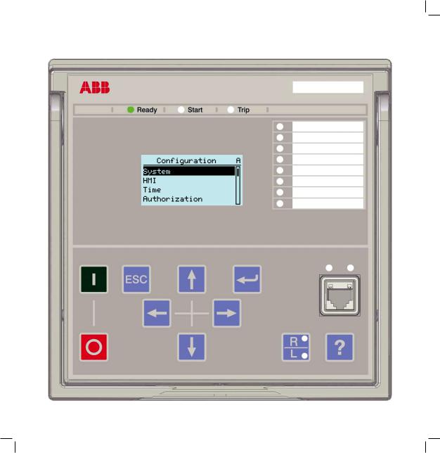
GUID-E15422BF-B3E6-4D02-8D43-D912D5EF0360 V1 EN
Figure 2: Example of the LHMI
3.2.1Display
The LHMI includes a graphical display that supports two character sizes. The character size depends on the selected language. The amount of characters and rows fitting the view depends on the character size.
Table 4: |
Small display |
|
|
|
|
|
|
Character size1) |
|
Rows in the view |
Characters per row |
Small, mono-spaced (6 × 12 pixels) |
5 |
20 |
|
|
|
|
|
Large, variable width (13 × 14 pixels) |
3 |
8 or more |
|
|
|
|
|
1) Depending on the selected language |
|
|
|
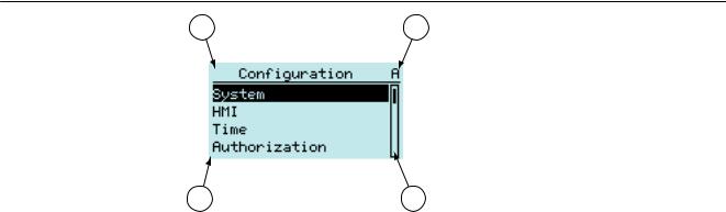
The display view is divided into four basic areas.
18 |
611 series |
|
Operation Manual |
1MRS757453 C |
Section 3 |
|
611 series overview |
1 |
2 |
3 |
4 |
Figure 3: |
Display layout |
1 Header
2 Icon
3 Content
4Scroll bar (displayed when needed)
•The header area at the top of the display view shows the current location in the menu structure.
•The icon area at the upper right corner of the display shows the current action or user level.
Current action is indicated by the following characters.
•U: Font/Firmware is being updated
•S: Parameters are being stored
•!: Warning and/or indication
Current user level is indicated by the following characters.
•V: Viewer
•O: Operator
•E: Engineer
•A: Administrator
•The content area shows the menu content.
•If the menu contains more rows than the display can show at a time, a scroll bar is displayed on the right.
The display is updated either cyclically or based on changes in the source data such as parameters or events.
3.2.2LEDs
The LHMI includes three protection indicators above the display: Ready, Start and
Trip.
611 series |
19 |
Operation Manual |
|
Section 3 |
1MRS757453 C |
611 series overview |
|
There are also 8 programmable LEDs on front of the LHMI. The LEDs can be configured with the LHMI, WHMI or PCM600.
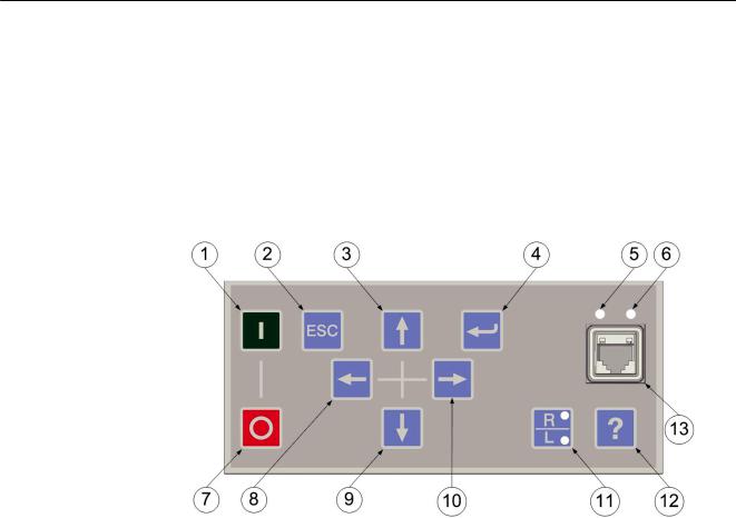
3.2.3Keypad
The LHMI keypad contains push buttons which are used to navigate in different views or menus. With the push buttons you can give open or close commands to one object in the primary circuit, for example, a circuit breaker, a contactor or a disconnector. The push buttons are also used to acknowledge alarms, reset indications, provide help and switch between local and remote control mode.
Figure 4: LHMI keypad with object control, navigation and command push buttons and RJ-45 communication port
1Close
2Escape
3Up
4Enter
5Uplink LED
6Communication LED
7Open
8 |
Left |
9 |
Down |
10Right
11Remote/Local
12Help
13Communication port
20 |
611 series |
|
Operation Manual |
1MRS757453 C |
Section 3 |
|
611 series overview |
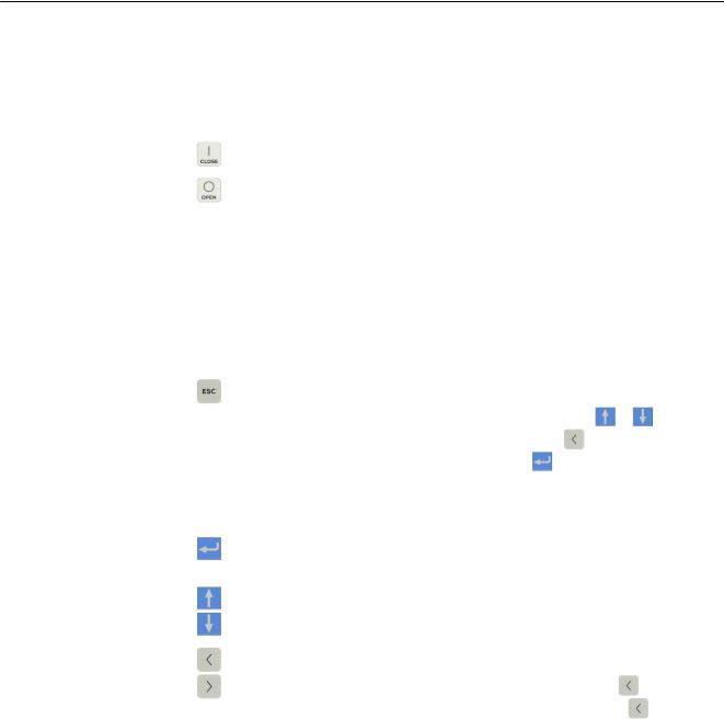
Object control
If the control position of the IED is set to local with the R/L button, the IED can be controlled using the object control buttons.
Table 5: |
Object control push buttons |
|
|
|
|
Name |
|
Description |
Close |
|
Closing the object. |
|
|
|
|
|
|
Open |
|
Opening the object. |
|
|
|
|
|
|
Navigation
The arrow buttons are used for navigation. To scroll information, press the arrow button several times or simply keep it pressed down.
Table 6: |
Navigation push buttons |
|
|
|
|
||
|
|
|
|
|
|
|
|
Name |
|
Description |
|
|
|
|
|
ESC |
|
• |
Leaving setting mode without saving the values. |
|
|
||
|
• |
Cancelling certain actions. |
|
|
|
|
|
|
|
• |
Adjusting the display contrast in combination with |
or |
. |
||
|
|
• |
|||||
|
|
Changing the language in combination with |
. |
|
|
||
|
|
• |
|
|
|||
|
|
Inserting a space in combination with |
when editing a string. |
||||
|
|
|
|||||
|
|
• |
Clearing indications and LEDs. The first three-second press clears the |
||||
|
|
|
indications. The second three-second press clears the programmable |
||||
|
|
|
LEDs. Requires appropriate user rights. |
|
|
|
|
|
|
|
|
|
|
|
|
Enter |
|
• |
Entering parameter setting mode. |
|
|
|
|
|
• |
Confirming a new value of a setting parameter. |
|
|
|
||
|
|
|
|
|
|
|
|
Up |
|
• |
Moving up and down in menus. |
|
|
|
|
|
• |
Scrolling active digits of a parameter when entering a new setting value. |
|||||
Down |
|
|
|
|
|
|
|
|
|
|
|
|
|
|
|
Left |
|
• |
Moving left and right in menus. |
|
|
|
|
|
• |
Changing the active digit of a parameter when entering a new setting value. |
|||||
Right |
|
• |
Deleting a character when editing a string by pressing |
|
. |
||
|
• |
|
|||||
|
|
Logging out, when the user is currently logged in. Press |
for three |
||||
|
|
|
|||||
|
|
|
seconds in the main menu. |
|
|
|
|
|
|
|
|
|
|
|
|
611 series |
21 |
Operation Manual |
|

Section 3 |
|
|
1MRS757453 C |
|
611 series overview |
|
|
|
|
|
|
|
|
|
|
Commands |
|
|
|
|
Table 7: |
Command push buttons |
||
|
|
|
|
|
|
Name |
|
Description |
|
|
R/L |
|
Changing the control position (remote or local) of the device. |
|
|
|
• |
When the R LED is lit, remote control is enabled and local control disabled. |
|
|
|
|
||
|
|
|
• |
When the L LED is lit, local control is enabled and remote control disabled. |
|
|
|
• |
When none of the LEDs are lit, both control positions are disabled. |
|
|
|
|
|
|
Help |
|
Showing context sensitive help messages. |
|
|
|
|
|
|
|
|
|
|
|
3.2.4Local HMI functionality
3.2.4.1Protection and alarm indication
Protection indicators
The protection indicator LEDs are Ready, Start and Trip.
Table 8: |
Ready LED |
|
|
|
|
|
|
LED state |
|
Description |
|
Off |
|
Auxiliary supply voltage is disconnected. |
|
|
|
|
|
On |
|
Normal operation. |
|
|
|
|
|
Flashing |
|
Internal fault has occurred or the protection relay is in test mode. Internal |
|
|
|
faults are accompanied by an indication message. |
|
|
|
|
|
Table 9: |
Start LED |
|
|
|
|
|
|
LED state |
|
Description |
|
Off |
|
Normal operation. |
|
|
|
|
|
On |
|
A protection function has started and an indication message is displayed. |
|
|
|
• |
If several protection functions start within a short time, the last start is |
|
|
|
indicated on the display. |
|
|
|
|
Flashing |
|
A protection function is blocked or the protection relay is in the test and |
|
|
|
blocked mode. |
|
|
|
• |
The blocking indication disappears when the blocking is removed or |
|
|
|
when the protection function is reset. |
|
|
|
|
22 |
611 series |
Operation Manual
Loading...