

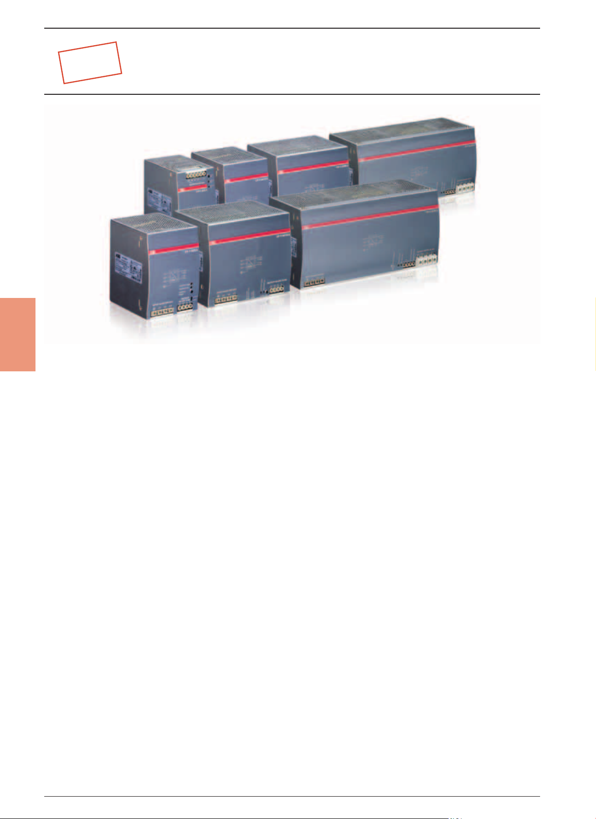
NEW
Primary switch mode power supplies
CP-T range
Benefits and advantages
4
Rated output voltages 24 V, 48 V DC
Output voltage adjustable via front-face rotary potentiometer “OUTPUT Adjust”
Rated output currents 5 A, 10 A, 20 A, 40 A
Rated output powers 120 W, 240 W, 480 W, 960 W
Three-phase or two-phase operation (see derating note)
Supply range 3 x 400 – 500 V AC (3 x 340 – 575 V AC, 480 – 820 V DC)
Typical efficiency of 93 %
Low power dissipation and low heating
Free convection cooling (no forced cooling with ventilators)
Ambient temperature range during operation -25...+70 °C
Open-circuit, overload and short-circuit stable
Integrated input fuse
Redundancy unit CP-A RU offering true redundancy, available as accessory
LEDs for status indication
Signalling contact "13-14" (Relay) for output voltage OK
Approvals / marks (depending on device, partly pending):
A, H / a , D, E, b
„DC OK“ output
The devices of the CP-T series offer
a relay contact for function monitoring
and remote diagnostics.
Wide range
Wide range input optimized for worldwide applications:
The CP-T power supplies can be used
in 3x340 - 575 V AC or 480 - 820 V DC
supply systems.
Adjustable output voltage
The CP-T range feature a
continuously adjustable output
voltage. Thus, they can be optimally adapted to the application,
e.g. compensating the voltage
drop caused by a long line
length.
4/28 ABB
2CDC110004C0207
NEW
Primary switch mode power supplies
CP-T range
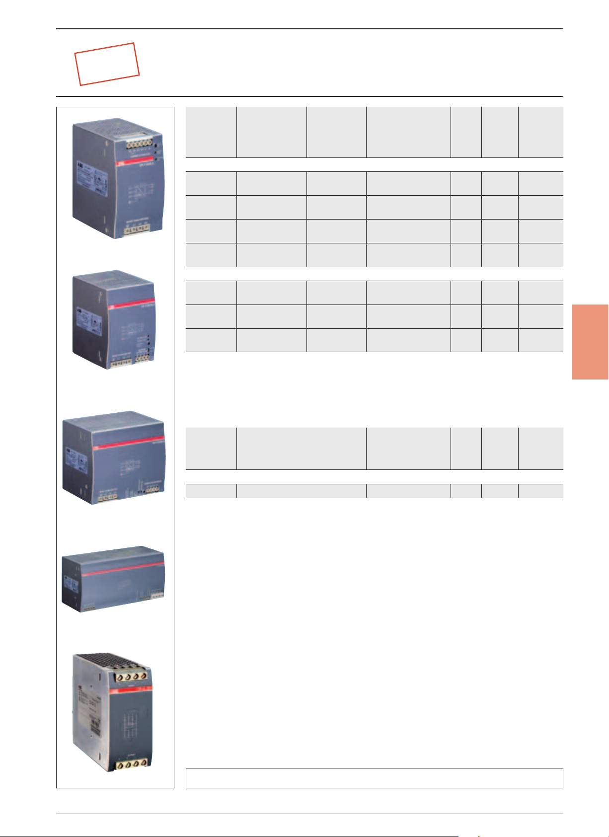
Ordering details
CP-T 24/5.0
CP-T 24/10.0
CP-T 48/5.0
Type
CP-T
24/5.0
CP-T
24/10.0
2CDC2710435S0009
CP-T
24/20.0
CP-T
24/40.0
CP-T
48/5.0
CP-T
48/10.0
CP-T
48/20.0
2CDC2710455S0009
Redundancy units
for decoupling of two CP-T power supply units
Input voltage
range
340-575 V AC/
480-820 V DC
340-575 V AC/
480-820 V DC
340-575 V AC/
480-820 V DC
340-575 V AC/
480-820 V DC
340-575 V AC/
480-820 V DC
340-575 V AC/
480-820 V DC
340-575 V AC/
480-820 V DC
Rated output
voltage /
current
24 V DC /
5 A
24 V DC /
10 A
24 V DC /
20 A
24 V DC /
40 A
48 V DC /
5 A
48 V DC /
10 A
48 V DC /
20 A
Order code
1SVR 427 054 R0000
1SVR 427 055 R0000
1SVR 427 056 R0000
1SVR 427 057 R0000
1SVR 427 054 R2000
1SVR 427 055 R2000
1SVR 427 056 R2000
Pack.
unit
pieces
Price
1 piece
1 0.8 / 1.77
1 1.05 / 2.31
1 1.75 / 3.86
1 3.20 / 7.05
1 1.05 / 2.31
1 1.75 / 3.86
1 3.4 / 7.50
Weight
1 piece
kg / lb
4
CP-T 24/20.0
CP-T 48/10.0
CP-T 24/40.0
CP-T 48/20.0
Type
CP-A RU: 2 inputs each up to 20 A and 1 output up to 40 A
2CDC2710475S00092CDC2710495S0009
CP-A RU
suitable for decoupling of two
CP-24 V DC power supply units
40 V and M 5 A
Order code
1SVR 427 071 R0000
Pack.
unit
pieces
Price
1 piece
1 0.89 / 1.96
Weight
1 piece
kg / lb
2CDC271010F0006
CP-A RU
• Approvals ...................................... 4/4
• Technical diagrams ..................... 4/34 • Technical data ..............................4/30 • Dimensional drawings .................... 4/34
ABB 4/29
2CDC110004C0207
4
Primary switch mode power supplies
NEW
Data at Ta = 25 °C, Uin = 3 x 400 V AC and rated values, unless otherwise indicated
Type CP-T 24/5.0 CP-T 24/10.0 CP-T 24/20.0 CP-T 24/40.0
Input circuit L1, L2, L3
Rated input voltage U
Input voltage range 340-575 V AC
Frequency range AC 47-63 Hz
Typical current consumption 0.36 A 0.85 A 1.1 A 1.72 A
Typical power consumption 135 W 270 W 538 W 1058 W
Inrush current limiting 10 A 20 A 30 A
Power failure buffering time min. 20 ms min. 15 ms
Internal input fuse per phase 2 A / 600 V AC T3.15 A / 500 V AC T 5 A / 500 V AC
Recommended backup fuse 3 pole miniature circuit breaker ABB Type S203
Power factor correction (PFC) Yes, passive
Discharge current towards PE < 3.5 mA
Indication of operational states
Output voltage OUTPUT OK: green LED output voltage OK
Output circuit L+, L+, L-, L-
Rated output voltage 24 V DC
Tolerance of the output voltage 0...+1 %
Adjustment range of the output
voltage
Rated output power 120 W 240 W 480 W 960 W
Rated output current Ir Ta ≤ 60 °C 5 A 10 A 20 A 40 A
Derating of the output current 60 °C < Ta ≤ 70 °C 2.5 %/°C 3.5 %/°C
Signalling contact
for output voltage OK
Maximum deviation with
Control time at nominal load < 2 ms
Starting time after applying
the supply voltage
Rise time at nominal load max. 150 ms
Fall time max. 150 ms
Residual ripple and switching peaks BW = 20 MHz 100 mV 80 mV
Parallel connection not
Series connection not supported yes, to increase voltage, max. 2 devices
Resistance to reverse feed approx. 35 V
Output circuit - No-load, overload and short-circuit behaviour
Characteristic curve of output combined U/I characteristic curve
Short-circuit protection continuous short-circuit proof
Short-circuit behaviour current limiting
in
CP-T range (24 V DC)
Technical data
3 x 400-500 V AC
480-820 V DC
input / output < 0.25 mA
OUTPUT LOW: red LED output voltage too low
22.5-28.5 V DC
13-14 Relay (max. 60 V DC, 0.3 A)
Threshold 17.6-19.4 V
Isolation voltage 500 V DC
load change statical
change of output voltage
within the input voltage range
at Ir max. 1 s
with 3500 µF max. 1.5 s
with 3500 µF max. 500 ms
supported
and hiccup mode
±1 % (single mode)
± 0.5 %
configurable, to increase
power, up to
2 devices, reduction:
(number of devices x I
± 5 % (parallel mode)
) x 0.9
r
U/I- or Hiccup-mode
adjustable
to increase
power, up to
2 devices, reduction:
(number of devices
x Ir) x 0.9, use active
current balancing
hiccup /
fold back behavior
4/30 ABB
2CDC110004C0207

Primary switch mode power supplies
NEW
Data at Ta = 25 °C, Uin = 3 x 400 V AC and rated values, unless otherwise indicated
Type CP-T 24/5.0 CP-T 24/10.0 CP-T 24/20.0 CP-T 24/40.0
Overload protection hiccup mode
No-load protection continuous no-load stability
Overtemperature protection yes, automatic recovery after temperature went down
Starting of capacitive loads 3500 µF 7000 µF 7000 µF 7000 µF
General data
Efficiency typ. 89 % typ. 90 % typ. 92 %
Duty time 100%
Dimensions (W x H x D)
Weight 24 / 5.0
Material of enclosure Metal
Mounting DIN rail (IEC EN 60715), snap-on mounting without any tool
Mounting position horizontal
Minimum distance to other units horizontal / vertical 25 mm / 25 mm (0.98 in / 0.98 in)
Degree of protection enclosure / terminals IP20 / IP20
Protection class I
Electrical connection - input circuit / output circuit
Wire size
Stripping length 8 mm (0.31 in)
Tightening torque input / output 1 Nm / 0.6 Nm 1 Nm / 1.8 Nm
Environmental data
Ambient temperature range operation -25…+70 °C
Damp heat (cyclic) (IEC/EN 60068-2-30) 95 % without condensation
Vibration (sinusoidal) (IEC/EN 60068-2-6) Random wave, 10-500 Hz, 2G, each along X, Y, Z axes 10 min / cycle, 60 min
Shock (half-sine) (IEC/EN 60068-2-27) Half sine wave, 4G, 22 ms, 3 axes, 6 Faces, 3 times for each face
Isolation data
Rated insulation voltage U
Pollution degree 2
Standards
Product standard
Low Voltage Directive 2006/95/EG
EMC directive 2004/108/EG
RoHS directive 2002/95/EG
Electrical safety IEC/EN 60950-1
Protective low voltage SELV
Electromagnetic compatibility
Interference immunity to IEC/EN 61000-6-2
electrostatic discharge IEC/EN 61000-4-2 Level 4
radiated, radio-frequency, electromagnetic field IEC/EN 61000-4-3
electrical fast transient/burst IEC/EN 61000-4-4 Level 4
surge IEC/EN 61000-4-5
conducted disturbances, induced by radio-frequency fields
Interference emission IEC/EN 61000-6-3
high-frequency radiated IEC/CISPR 22, EN 55022 Class B
high-frequency conducted IEC/CISPR 22, EN 55022 Class B
i
CP-T range (24 V DC)
Technical data
74.3 x 124 x 118.8 mm
[2.92 x 4.88 x 4.68 in]
0.78 kg (1.72 lb)
fine-strand with wire end ferrule 0.2-4 mm² (24-11 AWG)
fine-strand without wire end ferrule
rigid
rated load -25...+60 °C
storage -25…+85 °C
input circuit / output circuit 3 kV AC
input / PE 1.5 kV AC
L-N Level 3, L / N-FG
Level 4
IEC/EN 61000-4-6
89 x 124 x 118.8 mm
[3.5 x 4.88 x 4.68 in]
24 / 0.0
1.045 kg (2.30 lb)
0.2-6 mm² (24-10 AWG)
150 x 124 x 118.8 mm
[5.91 x 4.88 x 4.68 in]
24 / 20.0
1.657 kg (3.653 lb)
Level 3
L-N Level 3, L / N-G Level 4
Level 3
275.8 x 124 x 118.8 mm
[10.86 x 4.88 x 4.68 in]
24 / 40.0
3.275 kg (7.220 lb)
0.2-4 mm² (24-11 AWG) /
0.5-10 mm² (20-6 AWG)
4
• Approvals ..................................... 4/4
ABB 4/31
2CDC110004C0207

4
Primary switch mode power supplies
NEW
Data at Ta = 25 °C, Uin = 3 x 400 V AC and rated values, unless otherwise indicated
Type CP-T 48/5.0 CP-T 48/10.0 CP-T 48/20.0
Input circuit L1, L2, L3
Rated input voltage U
Input voltage ranget 340-575 V AC
Frequency range AC t
Typical current consumption 0.85 A 1.1 A 1.72 A
Typical power consumption 264 W 535 W 1050 W
Inrush current limiting 20 A 30 A
Power failure buffering time min. 20 ms min. 15 ms
Internal input fuse per phase 2 A / 600 V AC T3.15 A / 500 V AC T 5 A / 500 V AC
Power factor correction (PFC) yes, passive
Discharge current towards PE < 3.5 mA
Indication of operational states
Output voltage OUTPUT OK: green LED output voltage OK
Output circuit L+, L+, L-, L-
Rated output voltage 48 V DC
Tolerance of the output voltage 0...+1 %
Adjustment range of the output voltage 47-56 V DC
Rated output power 240 W 480 W 960 W
Rated output current I
Derating of the output current 60 °C < T
Maximum deviation with
Control time at rated load < 2 ms
Starting time after applying
the supply voltage
Rise time at rated load max. 150 ms
Fall time max. 150 ms
Residual ripple and switching peaks BW = 20 MHz 100 mV 80 mV
Parallel connection configurable, to increase power, up to 2 devices,
Series connection yes, to increase voltage, max. 2 devices
Resistance to reverse feed approx. 35 V approx. 63 V approx. 63 V
Output circuit - No-load, overload and short-circuit behaviour
Characteristic curve of output combined U/I and hiccup
Short-circuit protection continuous short-circuit proof
Short-circuit behaviour current limiting
Overload protection hiccup mode
No-load protection continuous no-load stability
Over temperature protection yes, automatic recovery after temperature went down
Starting of capacitive loads 7000 µF
in
r
CP-T range (48 V DC)
Technical data
input / output < 0.25 mA
OUTPUT LOW: red LED output voltage too low
Ta ≤ 60 °C 5 A 10 A 20 A
≤ 70 °C 2.5 %/°C 3.5 %/°C
a
load change statical
change of output voltage within the
input voltage range
at Ir max. 1 s
with 7000 µF max. 1.5 s
with 7000 µF max. 500 ms
3 x 400-500 V AC
480-820 V DC
±1 % (single mode)
± 5 % (parallel mode)
reduction: (number of devices x I
mode
U/I or hiccup mode,
configurable
±0.5 %
) x 0.9
r
to increase power, up to
2 devices, reduction:
(number of devices x I
x 0.9, use active current
balancing
hiccup mode /
fold back behavior
)
r
4/32 ABB
2CDC110004C0207

Primary switch mode power supplies
NEW
Data at Ta = 25 °C, Uin = 3 x 400 V AC and rated values, unless otherwise indicated
Type CP-T 48/5.0 CP-T 48/10.0 CP-T 48/20.0
General data
Efficiency typ. 91 % typ. 93 %
Duty time 100%
Dimensions (W x H x D) 89 x 124 x 118.8 mm
Weight 48 / 5.0
Material of enclosure Metal
Mounting DIN rail (IEC EN 60715), snap-on mounting without any tool
Mounting position horizontal
Minimum distance to other units horizontal / vertical 25 mm / 25 mm (0.98 in / 0.98 in)
Degree of protection enclosure / terminals IP20 / IP20
Protection class I
Electrical connection - input circuit / output circuit
Wire size
Stripping length 8 mm (0.31 in)
Tightening torque input / output 1 Nm / 0.6 Nm 1 Nm / 1.8 Nm
Environmental data
Ambient temperature range operation -25…+70 °C
Damp heat (cyclic) (IEC/EN 60068-2-30) 95 % without condensation
Vibration (sinusoidal) (IEC/EN 60068-2-6) Random wave, 10-500 Hz, 2G, each along X, Y, Z axes 10 min / cycle, 60 min
Shock (half-sine) (IEC/EN 60068-2-27) Half sine wave, 4G, 22 ms, 3 axes, 6 Faces, 3 times for each face
Isolation data
Rated insulation voltage U
Pollution degree 2
Standards
Product standard
Low Voltage Directive 2006/95/EG
EMC directive 2004/108/EG
RoHS directive 2002/95/EG
Electrical safety IEC/EN 60950-1
Protective low voltage SELV
Electromagnetic compatibility
Interference immunity to IEC/EN 61000-6-2
electrostatic discharge IEC/EN 61000-4-2 Level 4
radiated, radio-frequency, electromagnetic field IEC/EN 61000-4-3
electrical fast transient/burst IEC/EN 61000-4-4 Level 4
surge IEC/EN 61000-4-5 L-N Level 3, L / N-G Level 4
conducted disturbances, induced by radio-frequency fields
Interference emission IEC/EN 61000-6-3
high-frequency radiated IEC/CISPR 22, EN 55022 Class B
high-frequency conducted IEC/CISPR 22, EN 55022 Class B
i
CP-T range (48 V DC)
Technical data
[3.5 x 4.88 x 4.68 in]
1.045 kg (2.30 lb)
fine-strand with wire end ferrule 0.2-4 mm² (24-11 AWG)
fine-strand without wire end ferrule
rigid
rated load -25...+60 °C
storage -25…+85 °C
input circuit / output circuit 3 kV AC
input / PE 1.5 kV AC
IEC/EN 61000-4-6
150 x 124 x 118.8 mm
[5.91 x 4.88 x 4.68 in]
48 / 10.0
1.657 kg (3.653 lb)
0.2-6 mm² (24-10 AWG)
Level 3
Level 3
275.8 x 124 x 118.8 mm
[10.86 x 4.88 x 4.68 in]
48 / 20.0
3.275 kg (7.22 lb)
0.2-4 mm² (24-11 AWG) /
0.5-10 mm² (20-6 AWG)
4
• Approvals ..................................... 4/4
ABB 4/33
2CDC110004C0207

4
out
out
U
[V]
out
U
[V]
out
out
U
[V]
Primary switch mode power supplies
NEW
Technical diagrams dimensions in mm
Output curve at T
U
[V]
out
28
24
20
16
12
8
4
1 2 3 4 5 6 7 8
CP-T 24/5.0
[V]
U
out
28
24
20
16
12
8
4
4 8 12 16 20 24 28 32
CP-T 24/20.0 Hiccup mode
= 25 °C
U
CP-T range
Dimensional drawings
U
[V]
out
@ 3 x 400V supply
@ 3 x 500V supply
Hiccup mode
I
@ 3 x 400V supply
@ 3 x 500V supply
Hiccup mode
I
[A]
[A]
28
24
20
16
12
8
4
2CDC 272 032 F0x092CDC 272 035 F0x092CDC 272 038 F0x09
2 4 6 8 10 12 14 16
CP-T 24/10.0
U
[V]
out
28
24
20
16
12
8
4
8 16 24 32 40 48 56 64
CP-T 24/40.0 (preliminary curve)
@ 3 x 400V supply
@ 3 x 500V supply
Hiccup mode
I
[A]
@ 3 x 400V supply
@ 3 x 500V supply
Hiccup mode
72
[V]
U
out
2CDC 272 033 F0x092CDC 272 036 F0x092CDC 272 039 F0x09
28
24
20
16
12
8
4
4 8 12 16 20 24 28 32
@ 3 x 400V supply
@ 3 x 500V supply
[A]
I
CP-T 24/20.0 U/I curve
U
[V]
out
56
48
40
32
24
16
8
I
[A]
out
1 2 3 4 5 6 7 8
@ 3 x 400V supply
@ 3 x 500V supply
Hiccup mode
I
[A]
CP-T 48/5.0
2CDC 272 034 F0x092CDC 272 037 F0x092CDC 272 040 F0x09
out
56
48
40
32
24
16
8
2 4 6 8 10 12 14 16
@ 3 x 400V supply
@ 3 x 500V supply
CP-T 48/10.0 U/I curve
Temperature curve at rated load
in %
P
out
100
90
80
70
60
50
40
30
20
10
-25
CP-T < 960 W
89 3,5‘‘
I
out
60 70
out
56
48
40
32
24
16
8
[A]
2 4 6 8 10 12 14 16
@ 3 x 400V supply
@ 3 x 500V supply
Hiccup mode
I
out
[A]
CP-T 48/10.0 Hiccup mode
out
56
48
40
32
24
16
8
4 8 12 16 20 24 28
CP-T 48/20.0 (preliminary curve)
@ 3 x 400V supply
@ 3 x 500V supply
Hiccup mode
I
32
36
out
[A]
Dimensional drawings dimensions in mm
120-480 W
960 W
Tu in °C
2CDC 272 001 F0010
150 5,91‘‘
118,8 4,68’’
111,9 4,41‘‘
CP-T 24/5.0
131 5,16‘‘
74,3 2,92’’
124 4,88‘‘
2CDC 272 021 F0009
275.8 10.86‘‘
131 5,16‘‘
131 5,16‘‘
124 4,88‘‘
2CDC 272 022 F0009
124 4,88‘‘
2CDC 272 023 F0009
CP-T 24/20.0, CP-T 48/10.0CP-T 24/10.0, CP-T 48/5.0
131 5.16‘‘
124 4.88‘‘
CP-T 24/40.0, CP-T 48/20.0
2CDC 272 024 F0009
4/34 ABB
2CDC110004C0207
 Loading...