

Page 1
2CDC 293 036 F0004
Pluggable interface relays CR-U
Universal relays
Data sheet
Features
Standard universal relays with mechanical status indication 쐍
10 different supply voltages: 쐍
1
2
4
3
DC versions: 12 V, 24 V, 48 V, 110 V, 125 V, 220 V
AC versions: 24 V, 48 V, 60 V, 110 V, 120 V, 230 V
Output: 2 c/o (SPDT) contacts (10 A) or 3 c/o (SPDT) contacts (10 A) 쐍
Available with or without LED 쐍
Integrated test button for manual operation and locking of output contacts (blue = DC, orange = AC), 쐍
that can be removed if necessary
Cadmium-free contact material 쐍
Width on socket: 38 mm 쐍
Pluggable function modules: reverse polarity protection/free wheeling diode, LED indication, 쐍
RC elements, overvoltage protection, multifunction time module
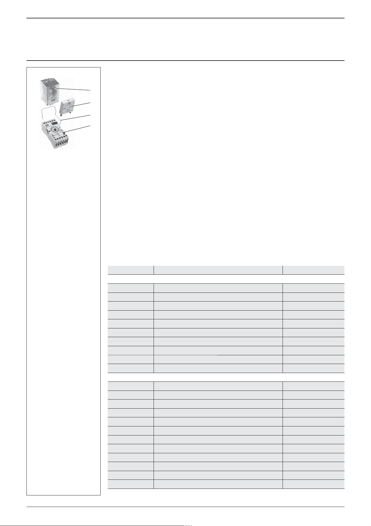
CR-U
Interface relay
Pluggable function
module
Socket
Holder
1
Approvals
G
UL508
O
CAN/CSA C22.2 No.14
F
CAN/CSA C22.2 No.14
J
VDE
D
GOST
P
Lloyds Register
E
CCC
L
RMRS
Marks
a
CE
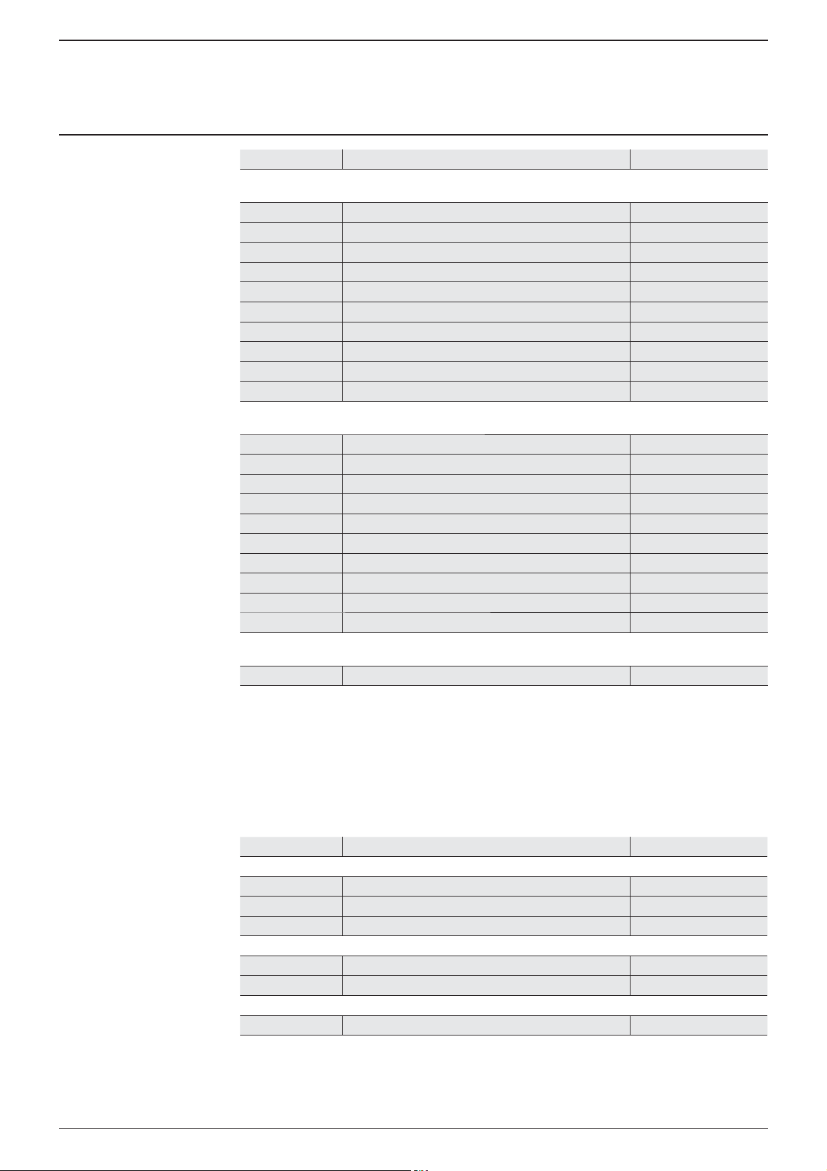
Order data
Type Rated control supply voltage U
Interface relays without LED, 2 c/o (SPDT) contacts: 250 V, 10 A
CR-U012DC2 12 V DC 1SVR 405 621 R4000
CR-U024DC2 24 V DC 1SVR 405 621 R1000
CR-U048DC2 48 V DC 1SVR 405 621 R6000
CR-U110DC2 110 V DC 1SVR 405 621 R8000
CR-U220DC2 220 V DC 1SVR 405 621 R9000
CR-U024AC2 24 V AC 1SVR 405 621 R0000
CR-U048AC2 48 V AC 1SVR 405 621 R5000
CR-U110AC2 110 V AC 1SVR 405 621 R7000
CR-U120AC2 120 V AC 1SVR 405 621 R2000
CR-U230AC2 230 V AC 1SVR 405 621 R3000
Interface relays without LED, 3 c/o (SPDT) contacts: 250 V, 10 A
CR-U012DC3 12 V DC 1SVR 405 622 R4000
CR-U024DC3 24 V DC 1SVR 405 622 R1000
CR-U048DC3 48 V DC 1SVR 405 622 R6000
CR-U110DC3 110 V DC 1SVR 405 622 R8000
CR-U125DC3 125 V DC 1SVR 405 622 R8200
CR-U220DC3 220 V DC 1SVR 405 622 R9000
CR-U024AC3 24 V AC 1SVR 405 622 R0000
CR-U048AC3 48 V AC 1SVR 405 622 R5000
CR-U060AC3 60 V AC 1SVR 405 622 R5200
CR-U110AC3 110 V AC 1SVR 405 622 R7000
CR-U120AC3 120 V AC 1SVR 405 622 R2000
CR-U230AC3 230 V AC 1SVR 405 622 R3000
Bold printed products = stocked products. Packing unit = 10 pieces.
S
Order code
Page 2
Pluggable interface relays CR-U
Universal relays
Data sheet
Type Rated control supply voltage U
Interface relays with LED
2 c/o (SPDT) contacts: 250 V, 10 A
CR-U012DC2L 12 V DC 1SVR 405 621 R4100
CR-U024DC2L 24 V DC 1SVR 405 621 R1100
CR-U048DC2L 48 V DC 1SVR 405 621 R6100
CR-U110DC2L 110 V DC 1SVR 405 621 R8100
CR-U220DC2L 220 V DC 1SVR 405 621 R9100
CR-U024AC2L 24 V AC 1SVR 405 621 R0100
CR-U048AC2L 48 V AC 1SVR 405 621 R5100
CR-U110AC2L 110 V AC 1SVR 405 621 R7100
CR-U120AC2L 120 V AC 1SVR 405 621 R2100
CR-U230AC2L 230 V AC 1SVR 405 621 R3100
Interface relays with LED
3 c/o (SPDT) contacts: 250 V, 10 A
CR-U012DC3L 12 V DC 1SVR 405 622 R4100
CR-U024DC3L 24 V DC 1SVR 405 622 R1100
CR-U048DC3L 48 V DC 1SVR 405 622 R6100
CR-U110DC3L 110 V DC 1SVR 405 622 R8100
CR-U220DC3L 220 V DC 1SVR 405 622 R9100
CR-U024AC3L 24 V AC 1SVR 405 622 R0100
CR-U048AC3L 48 V AC 1SVR 405 622 R5100
CR-U110AC3L 110 V AC 1SVR 405 622 R7100
CR-U120AC3L 120 V AC 1SVR 405 622 R2100
CR-U230AC3L 230 V AC 1SVR 405 622 R3100
Interface relays with LED and freewheeling diode
3 c/o (SPDT) contacts: 250 V, 10 A
CR-U024DC3LD 24 V DC 1SVR 405 623 R1100
S
Order code
Order data - Accessories
Sockets
Type Version Order code
Sockets
CR-U2S for 2 c/o (SPDT) contacts + module 1SVR 405 670 R0000
CR-U3S for 3 c/o (SPDT) contacts + module 1SVR 405 660 R0000
CR-U3E for 3 c/o (SPDT) contacts 1SVR 405 660 R0100
Small sockets
CR-U2SM for 2 c/o (SPDT) contacts 1SVR 405 670 R1100
CR-U3SM for 3 c/o (SPDT) contacts 1SVR 405 660 R1100
Accessories for CR-U sockets
CR-UH Metall holder 1SVR 405 669 R0000
Bold printed products = stocked products. Packing unit = 10 pieces.
2
Page 3
Pluggable interface relays CR-U
Universal relays
Data sheet
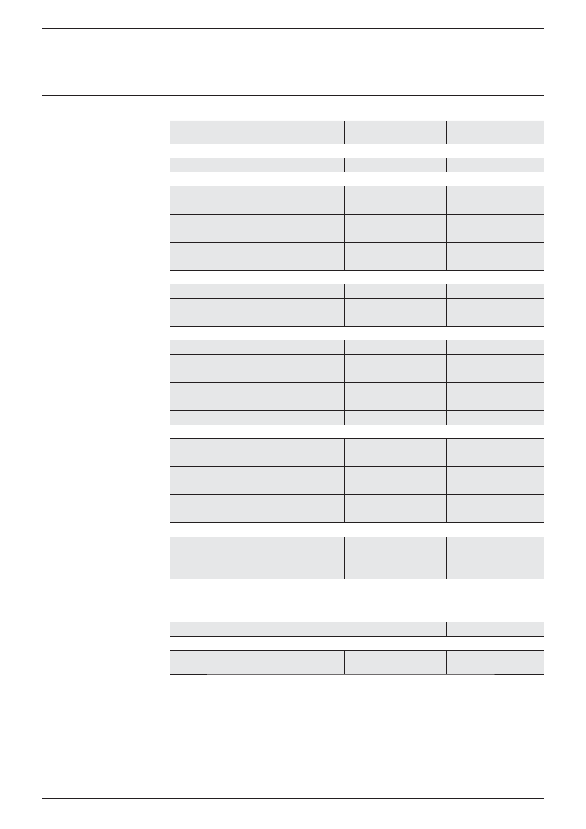
Function modules
Type Rated control
Diode - Reverse polarity protection
CR-U 21 6-230 V DC A1+, A2- 1SVR 405 661 R0000
Diode and LED - Reverse polarity protection
CR-U 41 6-24 V DC red, A1+, A2- 1SVR 405 662 R0000
CR-U 41V 6-24 V DC green, A1+, A2- 1SVR 405 662 R1000
CR-U 41B 24-60 V DC red, A1+, A2- 1SVR 405 662 R4000
CR-U 41BV 24-60 V DC green, A1+, A2- 1SVR 405 662 R4100
CR-U 41C 110-230 V DC red, A1+, A2- 1SVR 405 662 R9000
CR-U 41CV 110-230 V DC green, A1+, A2- 1SVR 405 662 R9100
RC element - Arc elemination
CR-U 51B 6-24 V AC 1SVR 405 663 R0000
CR-U 51D 24-60 V AC 1SVR 405 663 R4000
CR-U 51C 110-230 V AC 1SVR 405 663 R1000
Diode and LED
CR-U 61 6-24 V AC/DC red, for DC: A1+, A2- 1SVR 405 664 R0000
CR-U 61V 6-24 V AC/DC green, for DC: A1+, A2- 1SVR 405 664 R1000
CR-U 61E 24-60 V AC/DC red, for DC: A1+, A2- 1SVR 405 664 R4000
CR-U 61EV 24-60 V AC/DC green, for DC: A1+, A2- 1SVR 405 664 R4100
CR-U 91 110-230 V AC/DC red, for DC: A1+, A2- 1SVR 405 664 R0100
CR-U 91V 110-230 V AC/DC green, for DC: A1+, A2- 1SVR 405 664 R1100
Varistor and LED - Overvoltage protection
CR-U 61C 6-24 V AC/DC red, for DC: A1+, A2- 1SVR 405 665 R0000
CR-U 61CV 6-24 V AC/DC green, for DC: A1+, A2- 1SVR 405 665 R1000
CR-U 61D 24-60 V AC/DC red, for DC: A1+, A2- 1SVR 405 665 R4000
CR-U 61DV 24-60 V AC/DC green, for DC: A1+, A2- 1SVR 405 665 R4100
CR-U 91C 110-230 V AC/DC red, for DC: A1+, A2- 1SVR 405 665 R0100
CR-U 91CV 110-230 V AC/DC green, for DC: A1+, A2- 1SVR 405 665 R1100
Varistor - Overvoltage protection
CR-U 71 24 V AC 1SVR 405 666 R0000
CR-U 71A 115 V AC 1SVR 405 666 R1000
CR-U 81 230 V AC 1SVR 405 666 R2000
supply voltage U
S
Version Order code
Multifunction time module
Type Rated control supply voltage U
Multifunction timer module
CR-U T 24-240 V AC/DC pluggable onto CR-U2S
All CR-U modules can be plugged onto sockets CR-U2S and CR-U3S.
Bold printed products = stocked products. Packing unit = 10 pieces.
3
S
and CR-U3S
Order code
1SVR 405 667 R0000
Page 4

Pluggable interface relays CR-U
Universal relays
Data sheet
Application
Interface relays are electromechanic and electronic input and output modules for electrical isolation,
levelling, noise suppression or signal amplifi cation between control unit and process.
Operating mode
When power supply is applied, the output contacts get closed. When control supply voltage is switched
off, the contacts fall back into their starting position. Manual operation and locking of the output relays is
possible via the integrated test button.
Connection diagrams
Technical data
Input circuit - Coil data A1-A2
Rated control supply
voltage U
DC coils
AC coils
s
12 V DC - 9.6 V DC 13.2 V DC 욷 0.1 U
24 V DC - 19.2 V DC 26.4 V DC 욷 0.1 U
48 V DC - 38.4 V DC 52.8 V DC 욷 0.1 U
110 V DC - 88.0 V DC 121.0 V DC 욷 0.1 U
125 V DC - 96.0 V DC 132,0 V DC 욷 0.1 U
220 V DC - 176.0 V DC 242.0 V DC 욷 0.1 U
24 V AC 50 / 60 Hz 19.2 V AC 26.4 V AC 욷 0.15 U
48 V AC 50 / 60 Hz 38.4 V AC 52.8 V AC 욷 0.15 U
60 V AC 50 / 60 Hz 48.0 V AC 66,0 V AC 욷 0.15 U
110 V AC 50 / 60 Hz 88.0 V AC 121.0 V AC 욷 0.15 U
120 V AC 50 / 60 Hz 96.0 V AC 132.0 V AC 욷 0.15 U
230 V AC 50 / 60 Hz 184.0 V AC 253.0 V AC 욷 0.15 U
CR-U with 2 c/o (SPDT) contacts
A1-A2 Control supply voltage
11-12/14 Relay outputs
31-32/34
Rated
frequency
Make
voltage
(at 20 °C)
2CDC 292 024 F0004
Maxium
voltage
(at 55 °C)
Break
voltage
2CDC 292 030 F0004
CR-U with 3 c/o (SPDT) contacts
A1-A2 Control supply voltage
11-12/14 Relay outputs
21-22/24
31-32/34
Rated
power
Coil
resistance
(at 20 °C)
s
s
s
s
s
s
s
s
s
s
s
s
1.5 W 110 ⏲앐 10%
1.5 W 430 ⏲앐 10%
1.5 W 1750 ⏲앐 10%
1.5 W 9200 ⏲앐 10%
1.5 W 11000 ⏲앐 10%
1.5 W 37000 ⏲앐 10%
2.8 VA (50 Hz)
2.5 VA (60 Hz)
2.8 VA (50 Hz)
2.5 VA (60 Hz)
2.8 VA (50 Hz)
2.5 VA (60 Hz)
2.8 VA (50 Hz)
2.5 VA (60 Hz)
2.8 VA (50 Hz)
2.5 VA (60 Hz)
2.8 VA (50 Hz)
2.5 VA (60 Hz)
75 ⏲앐 10%
305 ⏲앐 10%
475 ⏲앐 10%
1700 ⏲앐 10%
1910 ⏲앐 10%
7080 ⏲앐 10%
Tolerance
of coil
resistance
4
Page 5

Pluggable interface relays CR-U
Universal relays
Data sheet
Type CR-U...2 CR-U...3
Output circuits 11-12/14, 31-32/34 11-12/14, 21-22/24, 31-32/34
Kind of output Relay, 2 c/o contacts Relay, 3 c/o contacts
Contact material AgNi
Rated operational voltage U
Min. switching voltage 5 V
Max. switching voltage DC 250 V DC
Min. switching current 5 mA
Conventional free-air thermal current I
Rated operational current
(IEC 60947-5-1)
Max. making current 20 A
Min. switching power 0.3 W
Max. switching power AC1 2500 VA
Contact resistance 울 100 m⏲
Max. switching capacity rated load AC1 1200 switching cycles / h
Lifetime mechanical 욷 2 x 10
Response time typ. 18 ms (DC) / typ. 12 ms (AC)
Release time typ. 7 ms (DC) / typ. 10 ms (AC)
Isolation data
Rated insulation voltage 250 V AC
Insulation class C250
Rated impulse withstand voltage U
Clearance between coil and contacts 욷 3 mm
Creepage distance between coil and contacts 욷 4.2 mm
Overvoltage category III
Pollution degree 3
General data
Dimensions (W x H x D) when mounted 35 x 35 x 54.4 mm
Weight 83 g (0.18 lb)
Mounting on socket (see accessories)
Mounting position any
Degree of protection IP 40
Electrical connection
Connection by socket
Environmental data
Ambient temperature range operation DC -40...+70 °C
Vibration resistance (10-150 Hz) n/o contacts 5 g
Shock resistance n/o contacts 10 g
Standards
Product standards EN 60255-1-00
Low Voltage Directive 73/23/EEC
5
(VDE 0110, IEC 60947-1) 250 V
e
AC 250 V AC
th
AC12 (resistive) 230 V 10 A
AC15 (inductive) 230 V 1.5 A
DC12 (resistive) 24 V 10 A
DC13 (inductive) 24 V 2 A
without load 12000 switching cycles / h
electrical AC1 (resistive) 욷 10
cos ϕ see reduction factor F
between coil and contacts 2.5 kV AC
imp
open contacts 1.5 kV AC
c/o (SPDT) contacts 2 kV AC
AC -40...+55 °C
storage -40...+85 °C
n/c contacts 5 g
n/c contacts 10 g
10 A
7
switching cycles
5
switching cycles (10 A, 250 V)
Page 6

2CDC 292 025 F0004
Pluggable interface relays CR-U
Universal relays
Data sheet
Technical diagrams
Load limit curve Maximum switching power
at resistive DC load
1 = resistive load, T = 0 ms
2 = inductive load, T = 40 ms
DC current [A]
DC voltage [V]
2CDC 292 028 F0204
Reduction factor F at inductive AC load
Reduction factor
Load limit curve Electrical lifetime
at resistive AC load
Switching cycles
Switching power [kVA]
2CDC 292 037 F2004
Power factor
2CDC 292 029 F0204
Dimensions in mm
2CDC 292 026 F0004
Versions with 2 c/o contacts (CR-U ... 2) Versions with 3 c/o contacts (CR-U ... 3)
Further documentation
Document title Document type Document number
Sockets CR-U Data sheet 2CDC 117 006 D010x
Pluggable function modules CR-U Data sheet 2CDC 117 008 D010x
Pluggable multifunction time module CR-U T Data sheet 2CDC 117 010 D010x
6
Page 7

As part of the on-going product improvement, ABB reserves
the right to modify the characteristics of the products
described in this document. The information given is
non-contractual.
For further details please contact (www.abb.com/contacts)
ABB STOTZ-KONTAKT GmbH
Eppelheimer Strasse 82, 69123 Heidelberg, Germany
Postfach 10 16 80, 69006 Heidelberg, Germany
Internet http://www.abb.com/lowvoltage 씮 Control Products
Contact: http://www.abb.com/contacts 씮 Low Voltage Products and Systems
the ABB company marketing these products in your country.
Document number: 2CDC 117 003 D0205 (06/2009)
 Loading...